Embed Size (px)
Citation preview

Electromagnetic Flow Meter
www.fine-tek.com
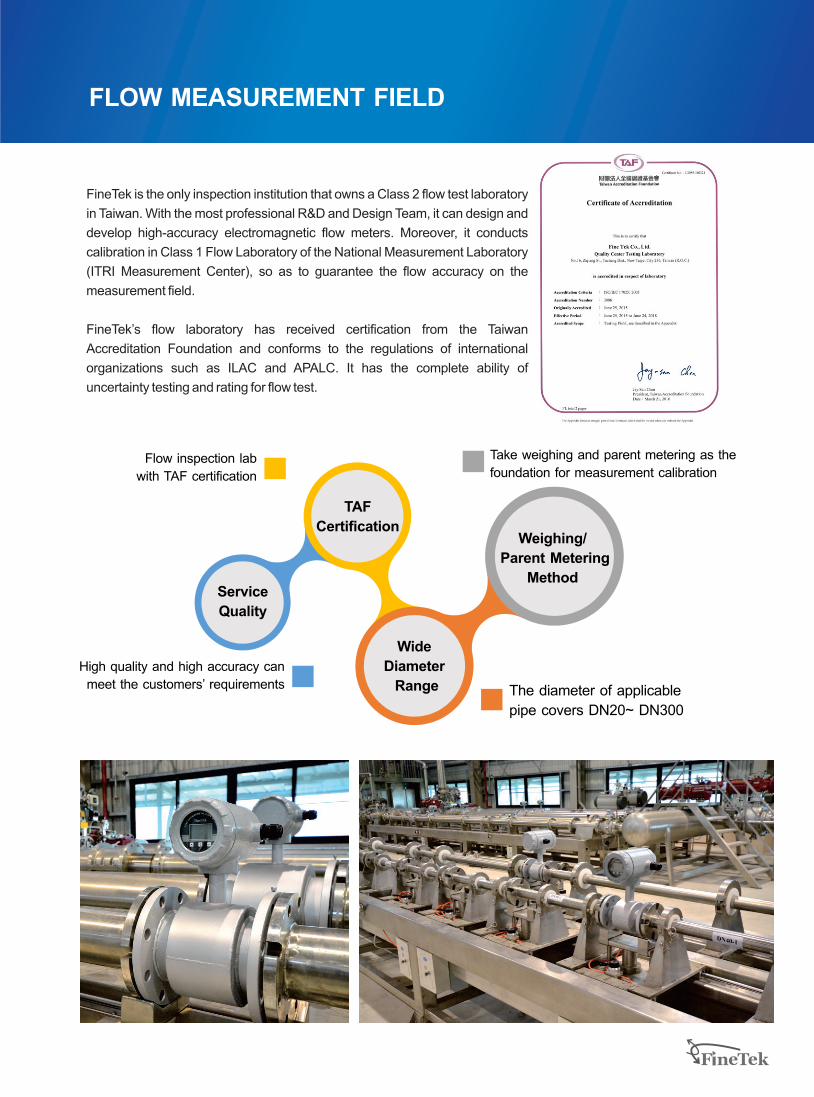
FineTek is the only inspection institution that owns a Class 2 flow test laboratory
in Taiwan. With the most professional R&D and Design Team, it can design and
develop high-accuracy electromagnetic flow meters. Moreover, it conducts
calibration in Class 1 Flow Laboratory of the National Measurement Laboratory
(ITRI Measurement Center), so as to guarantee the flow accuracy on the
measurement field.
FineTek’s flow laboratory has received certification from the Taiwan
Accreditation Foundation and conforms to the regulations of international
organizations such as ILAC and APALC. It has the complete ability of
uncertainty testing and rating for flow test.
FLOW MEASUREMENT FIELD
Weighing/
Parent Metering
Method
TAF
Certification
Service
Quality
Wide
Diameter
Range
Take weighing and parent metering as the
foundation for measurement calibration
The diameter of applicable
pipe covers DN20~ DN300
High quality and high accuracy can
meet the customers’ requirements
Flow inspection lab
with TAF certification

PUMP equipment(The maximum horsepower
is 110KW per unit)
Weighing equipment
Control room & Graphical HMI
Piping system I
(Max capacity for four meters calibration
simultaneously in above system.)
Piping system II
(Maximum diameter is 300mm)The exclusive report
(Each flow meter has its own calibration report)
FLOW MEASUREMENT FIELD

1
EPD electromagnetic flow meter is a high-accuracy flow meter manufactured based on the latest
international technology. It is widely applied in papermaking, chemical industry, metallurgical industry,
drainage, waste water treatment, liquid high-pressure metering, medical care, food, and environmental
protection industries. It is used to measure the non-magnetic liquid and plasma in the enclosed pipe.
WORKING PRINCIPLE
APPLICATIONS
Waste water treatmentTapped water purification Sewerage Sea water desalination moduleDyeing machinesSolar energy and PCB wet processingFood manufacturing Pharmaceutical machines
The working principle of the electromagnetic flow
meter is based on the Faraday law of
electromagnetic induction. When the conducting
liquid flows in the orthogonal direction of the
magnetic line direction, it will cut the magnetic lines
and generate induced voltage, which shows linear
relationship with the flowing speed. Thus, the fluidic
volume flow can be calculated.
EPD electromagnetic flow meter is mainly
composed of the sensor and transmitter. The
measuring tube of the sensor is equipped with the
excitation coils upward and downward. The
transmitter supplies the excitation current, which
generates the magnetic field which goes through
the measuring tube once it is powered on. A pair of
induction electrodes installed on the inner side of
the measuring tube comes in contact with the liquid
to guide the induced voltage to the sensor.
ELECTROMAGNETIC FLOW METER
Magnetic coil
liquid
Measuring pipe
Electrode
ID:D
Flow speed:V
Voltage:E
Strength of magnetic:B
FEATURES
Low impact on environmental matterThe measurement results are not affected by
the change in liquid density, viscosity,
temperature, pressure and conductivity. It can be widely applied in the conducting
liquids that may contain fiber, solid granules and
suspended matters. Enclosure protection rating: IP67/NEMA 4X
Wide measurement range & high efficiency The wide measurement turndown ratio can be
reach 1:100, which can be set randomly and
achieve high accuracy for small flow
measurement.Highly-integrated backlit display of two rows,
dual isolation, parameter setting, menu-type
operation, memory function, reliable
programming, password lock and access, small
signal elimination, non-linear correction and two-
way measurement. Various outputs: Current output 4~20mA,
frequency output 2~8KHz and RS485
communication.
Multiple self-diagnosis function Power-saving and low fault rate: The measuring
tube is without baffle and movable parts, so it
won’t cause pressure loss and jam. Smart self-detection and self-diagnosis function,
as well as various alarms
The low installation costIt is easy-to-install with low requirements for the
straight tube section (Front 5D and rear 2D) 2-wire analog output

2
Item
Buttons
Display
Communication interface
Accuracy
Medium temperature
Ambient temperature
Fluidic conductivity
Measuring scope
Current output accuracy
Current output mode
Analog output
Maximum load of current output
Alarming current
Frequency output scope
Pulse width
Pulse mode NPN transistor output 32vdc/200mA
Tri-button operation
LCM 128*64 pixel backlit type
RS-485 (Modbus) (Optional support for ZigBee Pro wireless transmission)
-40 ~ 70 1BC
±0.5% of reading@1m/s(0.2% al)option
> 5 uS/cm
0.1m/s ~ 10m/s
0.1% of Pulse Output AccuracyTemperature coefficient (100ppm/BC)
Proactive
4 ~ 20mA
< 700Ω
3.6mA or 22 mA
2 ~ 8 Hz
Automatic (pulse width 50%)
Time constant
Control output (DO)
Control input (DI)
Baud rate
Protection rating
Enclosure material
Input power
Power consumption < 10W
0.1~20 s
NPN 32vdc/200mA ;2-CHtransistor output
Dry contact ON< 200Ω ; 1,000Ω< OFF ; 1-CH
1200 ~ 38400 bps
IP67 / NEMA 4X
Aluminum alloy
AC 100~240V or DC 24V
Wire inlet specification
Excitation mode
Vibration regulation IEC 60068-2-3
M20 x 1.5*2 Female
Pulse DC
EMC regulation IEC/EN 61326-1 Class A table2
-20 ~ 120 BC
1 It can’t display when LCM is lower than -20℃.2 Continuous immersion in 6 meters of water for up to 48 hours.
SPECIFICATION
0~100 s
1200 ~ 57600 bps
Operating pressure 10Kg/cm2
EPD30 Standard type EPD34 Remote type
IP68 (Transducer)IP67/ NEMA 4X (Transmitter)
2
3
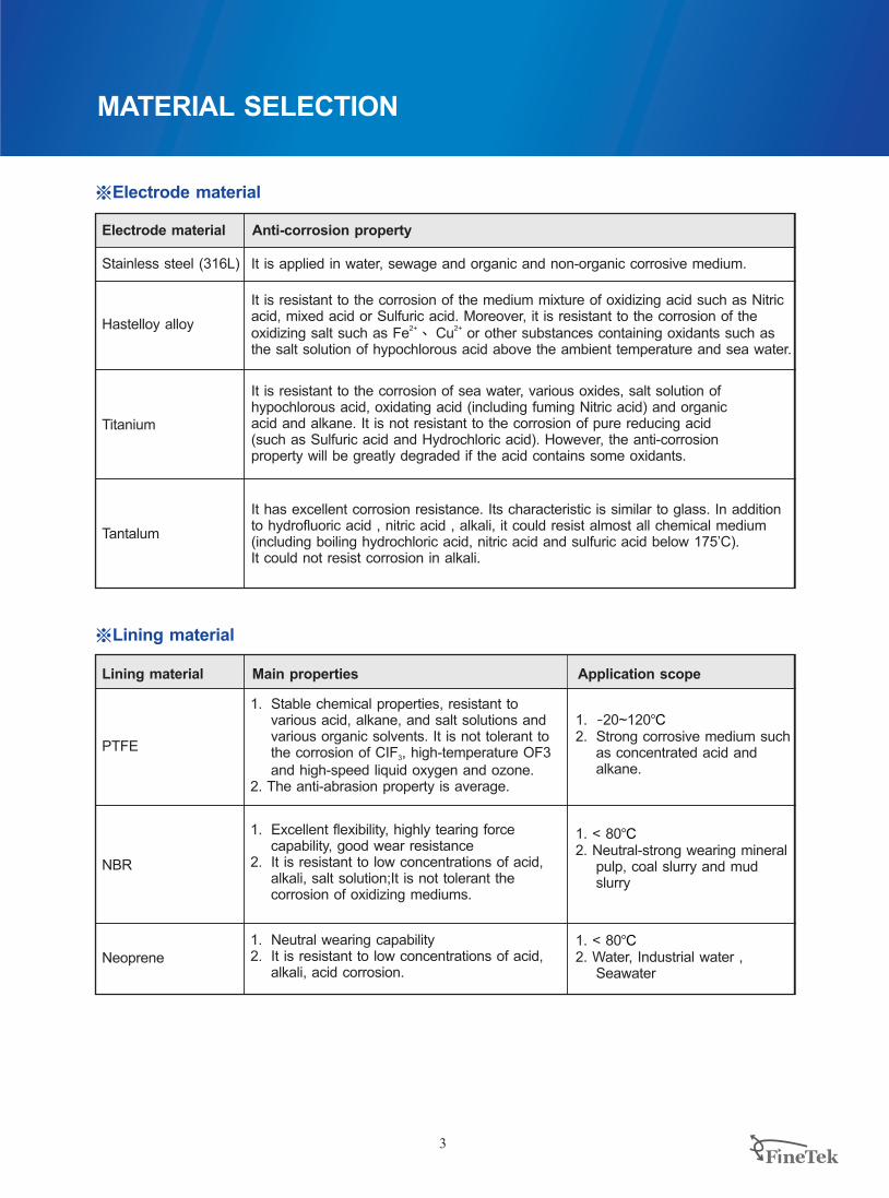
Electrode material
Stainless steel (316L)
Hastelloy alloy
Titanium
Anti-corrosion property
It is applied in water, sewage and organic and non-organic corrosive medium.
※Electrode material
It is resistant to the corrosion of the medium mixture of oxidizing acid such as Nitricacid, mixed acid or Sulfuric acid. Moreover, it is resistant to the corrosion of the
2+ 2+oxidizing salt such as Fe 、 Cu or other substances containing oxidants such as the salt solution of hypochlorous acid above the ambient temperature and sea water.
It is resistant to the corrosion of sea water, various oxides, salt solution of hypochlorous acid, oxidating acid (including fuming Nitric acid) and organic acid and alkane. It is not resistant to the corrosion of pure reducing acid (such as Sulfuric acid and Hydrochloric acid). However, the anti-corrosion property will be greatly degraded if the acid contains some oxidants.
※Lining material
Lining material
PTFE
Main properties Application scope
1. Stable chemical properties, resistant to various acid, alkane, and salt solutions and various organic solvents. It is not tolerant to the corrosion of CIF , high-temperature OF3 3
and high-speed liquid oxygen and ozone. 2. The anti-abrasion property is average.
1. -20~1202. Strong corrosive medium such
as concentrated acid and alkane.
BC
MATERIAL SELECTION
Tantalum
It has excellent corrosion resistance. Its characteristic is similar to glass. In additionto hydrofluoric acid , nitric acid , alkali, it could resist almost all chemical medium(including boiling hydrochloric acid, nitric acid and sulfuric acid below 175’C). It could not resist corrosion in alkali.
NBR
1. Excellent flexibility, highly tearing force capability, good wear resistance
2. It is resistant to low concentrations of acid, alkali, salt solution;It is not tolerant the corrosion of oxidizing mediums.
1. < 802. Neutral-strong wearing mineral
pulp, coal slurry and mud slurry
BC
Neoprene1. Neutral wearing capability2. It is resistant to low concentrations of acid,
alkali, acid corrosion.
1. < 802. Water, Industrial water ,
Seawater
BC

4
Connection specification
Nominal diameter(mm)
Lining material
Length
External diameter
PCD
Flange thickness
Inclined angle of screw hole
Diameter of screw hole
Height of sensor casing
Quantity of screw holes
Total height
Weight (kg)
L
fD
fC
t
q°
qh
N
H1
H2
Connection specification
Nominal diameter(mm)
Lining material
APPEARANCE AND DIMENSION ANDFLANGE CONNECTION DIMENSION STANDARD TYPE
300
JIS 20K
L
PTFE
fD
fC
t
q°
qh
N
H1
40
200
140
105
18
45
19
4
125
7.08
50
200
155
120
18
22.5
19
8
125
7.72
65 80 100 125 150 200 250
200
175
140
20
22.5
23
8
145
8.98
200
200
160
22
22.5
23
8
145
12 25.
250
225
185
24
22.5
23
8
195
16 42.
250
270
225
26
22.5
25
8
195
23 56.
300
305
260
28
15
25
12
270
31 03.
350
350
305
30
15
25
12
305
43 37.
400 500
430 480
380 430
34 36
15
27 27
12 16
365 406
74 23. 94 15.
11.25
Length
External diameter
PCD
Flange thickness
Diameter of screw hole
Height of sensor casing
Quantity of screw holes
Total height
Inclined angle of screw hole
Weight (kg)
300
JIS 10K
PTFE
40
200
140
105
14
45
19
4
125
6.8
50
200
155
120
14
45
19
4
125
7.68
65 80 100 125 150 200 250
200
175
140
16
45
19
4
145
8.98
200
185
150
16
22.5
19
8
145
9.87
250
210
175
16
22.5
19
8
195
12.9
250
250
210
20
22.5
19
8
195
17.5
300
280
240
22
22.5
23
8
270
23.51
350
330
290
22
15
23
12
305
33.23
400 500
400 445
355 400
24 24
15
25 25
12 16
365 406
54.03 69.55
11.25
H2 314.5 322 414.5342 354.5 392 478 514 585 632
315 322 404.5342 347 384.5 467 506 572 616
DN40~80 DN100~300
t
H1 fD
q°
H2
fC
fN-qh
L L
t
H1 fD
fN-qh
H2
fC
q°
Notice: The thickness of lining protection ring (grounding) for DN40 to DN80 is 2 mm; The total length of EPD Electromagnetic Flow Meter is L+ 4 mm. The thickness of lining protection ring (grounding) for DN100 to DN300 is 0.5 mm; The total length of EPD Electromagnetic Flow Meter is L+1 mm. Size tolerance: Total length is ±3mm; Total height is ±5mm.

5
APPEARANCE AND DIMENSION ANDFLANGE CONNECTION DIMENSION STANDARD TYPE
JIS 7.5K
PTFE
50
200
155
120
18
45
19
4
125
322
80(75)
200
211
168
21
45
19
4
145
360
100 125 150 200
511
250 300
250
238
185
24
45
19
4
195
399
250
263
225
26
30
19
6
195
411
300
290
247
23
30
19
6
270
472
350
342
299
24
22.5
19
8
305
400
410
360
26
22.5
23
8
365
577
500
464
414
28
18
23
10
406
625
Connection specification
Nominal diameter(mm)
Lining material
Length
External diameter
PCD
Flange thickness
Inclined angle of screw hole
Diameter of screw hole
Height of sensor casing
Quantity of screw holes
Total height
Weight (kg)
L
fD
fC
t
q°
qh
N
H1
H2
DN40~80 DN100~300
t
H1 fD
q°
H2
fC
fN-qh
L L
t
H1 fD
fN-qh
H2
fC
q°
Notice: The thickness of lining protection ring (grounding) for DN40 to DN80 is 2 mm; The total length of EPD Electromagnetic Flow Meter is L+ 4 mm. The thickness of lining protection ring (grounding) for DN100 to DN300 is 0.5 mm; The total length of EPD Electromagnetic Flow Meter is L+1 mm. Size tolerance: Total length is ±3mm;Total height is ±5mm.

6
Connection specification
Nominal diameter(mm)
Lining material
Inclined angle of screw hole
Length
External diameter
PCD
Flange thickness
Diameter of screw hole
Height of sensor casing
Quantity of screw holes
Total height
Weight (kg)
ANSI 300LbsConnection specification
Nominal diameter(mm)
Lining material
Inclined angle of screw hole
Length
External diameter
PCD
Flange thickness
Diameter of screw hole
Height of sensor casing
Quantity of screw holes
Total height
Weight (kg)
APPEARANCE AND DIMENSION ANDFLANGE CONNECTION DIMENSION STANDARD TYPE
511 575321 344 350 394 407 464308 633
44.17 67.238.32 10.78 12.25 17.82 20.96 27.03
300250
400
406.4
361.9
28.6
15
25.4
12
365
500
482.6
431.8
30.2
15
25.4
12
406
6.48
27
99.55
250 300
327 350 360 407 419 481 528323 592 650
200
165
127
20.6
22.5
19
8
125
200
190
149.2
23.8
22.5
22.2
8
145
200
210
168.3
27
22.5
22.2
8
145
250
254
200
30.2
22.5
22.2
8
195
250
279
235
33.3
22.5
22.2
8
195
300
317.5
269.9
34.9
15
22.2
12
265
350
381
330.2
39.7
15
25.4
12
305
200
156
114.3
19
45
22.2
4
125
10.32 12.78 16.45 26.62 32.96 43.83 69.17 100.43 146.69.08
400
444.5
387.35
46
11.3
28.6
16
365
500
520.7
450.9
49.2
11.3
31.8
16
406
DN40~80 DN100~300
t
H1 fD
q°
H2
fC
fN-qh
L L
t
H1 fD
fN-qh
H2
fC
q°
Notice: The thickness of lining protection ring (grounding) for DN40 to DN80 is 2 mm; The total length of EPD Electromagnetic Flow Meter is L+ 4 mm. The thickness of lining protection ring (grounding) for DN100 to DN300 is 0.5 mm; The total length of EPD Electromagnetic Flow Meter is L+1 mm. Size tolerance: Total length is ±3mm; Total height is ±5mm.

7
DN40~80 DN100~200
t
H1 fD
q°
H2
fC
fN-qh
L L
t
H1 fD
fN-qh
H2
fC
q°
20040 50 65 80 65 80 100 125 150
DIN PN40 DIN PN16
L
fD
fC
t
q°
qh
N
H1
H2
Connection specification
Nominal diameter(mm)
Lining material
Inclined angle of screw hole
Length
External diameter
PCD
Flange thickness
Diameter of screw hole
Height of sensor casing
Quantity of screw holes
Total height
Weight (kg)
L
fD
fC
t
q°
qh
N
H1
H2
Connection specification
Nominal diameter(mm)
Lining material
Inclined angle of screw hole
Length
External diameter
PCD
Flange thickness
Diameter of screw hole
Height of sensor casing
Quantity of screw holes
Total height
Weight (kg)
200 250 300
DIN PN10
PTFE
APPEARANCE AND DIMENSION ANDFLANGE CONNECTION DIMENSION STANDARD TYPE
320 327 355347 355 347 390 405 470 510
200
150
110
18
45
18
4
125
7.08
200
165
125
20
45
18
4
125
7.72
200
185
145
22
22.5
18
8
145
8.98
200
200
160
24
22.5
18
8
145
12.25
200
185
145
18
45
18
4
145
8.58
200
200
160
20
22.5
18
8
145
11.65
250
220
180
20
22.5
18
8
195
15.62
250
250
210
22
22.5
18
8
195
20.96
300 350
285 340
240 295
22 24
22.5
22 22
8 12
265 305
28.23 39.97
15
510 568 637
350
340
295
24
22.5
22
8
305
33.23
400
395
350
26
15
22
12
365
54.03
500
445
400
26
15
22
12
406
69.55
Notice: The thickness of lining protection ring (grounding) for DN40 to DN80 is 2 mm; The total length of EPD Electromagnetic Flow Meter is L+ 4 mm. The thickness of lining protection ring (grounding) for DN100 to DN300 is 0.5 mm; The total length of EPD Electromagnetic Flow Meter is L+1 mm. Size tolerance: Total length is ±3mm; Total height is ±5mm.
8
*1: The thickness of lining protection ring (grounding) for DN40 to DN80 is 2 mm; The total length of EPD Electromagnetic Flow Meter is L+ 4 mm. The thickness of lining protection ring (grounding) for DN100 to DN300 is 0.5 mm; The total length of EPD Electromagnetic Flow Meter is L+1 mm. Size tolerance: Total length is ±3mm; Total height is ±5mm.*2: To shows the weight of sensor only. Not include the weight of transmitter 2.06kg
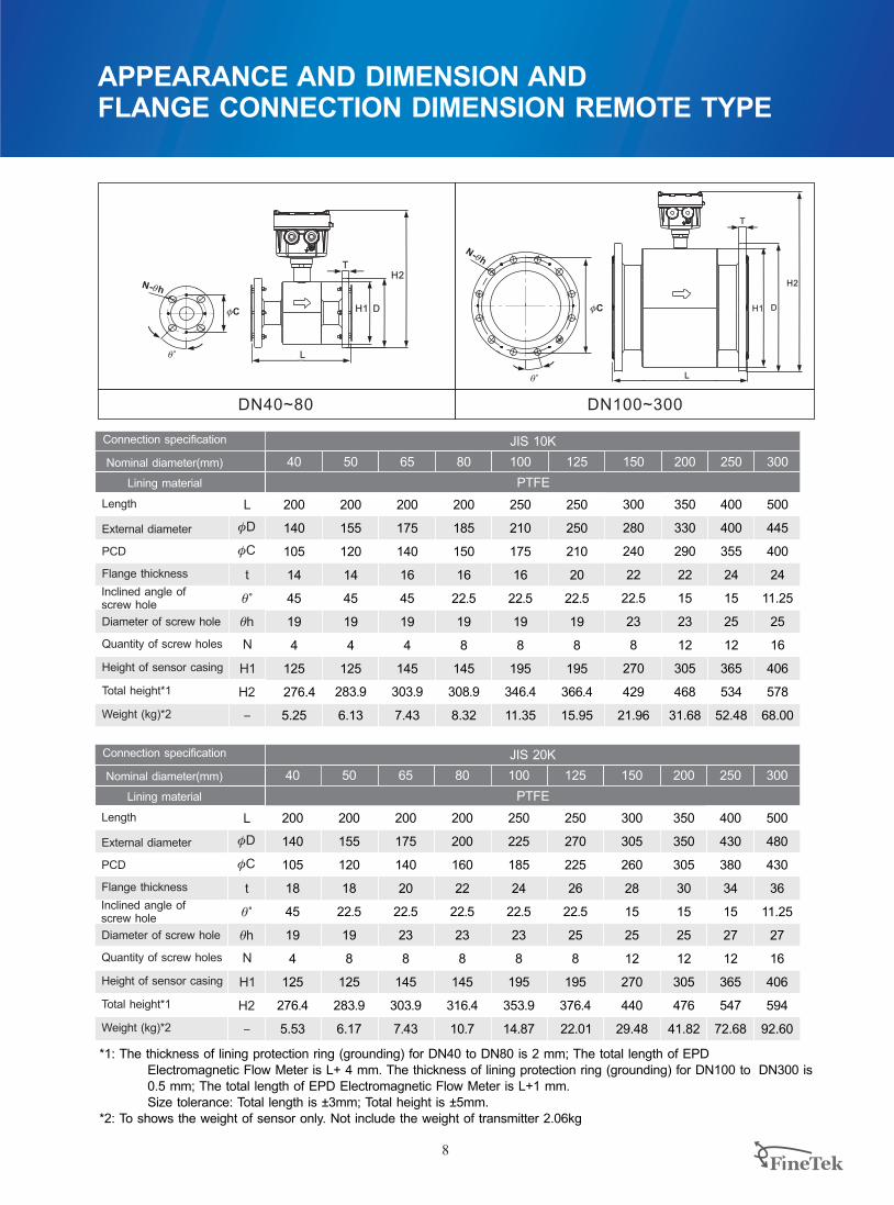
JIS 10K
PTFE
40 50 65 100 125
200
140
105
14
45
19
4
125
276.4
5.25
200
155
120
14
45
19
4
125
283.9
6.13
200
175
140
16
45
19
4
145
303.9
250
210
175
16
22.5
19
8
195
346.4
11.35
250
250
210
20
22.5
19
8
195
15.95
366.4
150 200 250 300
300
280
240
22
22.5
23
8
270
429
21.96
500
445
400
24
25
16
406
578
400
400
355
24
15
25
12
365
534
350
330
290
22
15
23
12
305
468
31.68
11.25
52.48 68.00
80
200
185
150
16
22.5
19
8
145
308.9
8.327.43
L
fD
fC
t
q°
qh
N
H1
H2
-
Connection specification
Nominal diameter(mm)
Lining material
Inclined angle ofscrew hole
Length
External diameter
PCD
Flange thickness
Diameter of screw hole
Height of sensor casing
Quantity of screw holes
Total height*1
Weight (kg)*2
150 200 250 300
500
480
430
36
27
16
406
594
PTFE
300
305
260
28
15
25
12
270
440
350
350
305
30
15
25
12
305
476
400
430
380
34
15
27
12
365
547
11.25
JIS 20K
40 50 125
200 200
140 155
105 120
18 18
45 22.5
19 19
4 8
125 125
276.4 283.9
250
270
225
26
22.5
25
8
195
376.4
5.53 6.17 22.01 29.48 41.82 72.68 92.60
80
200
200
160
22
22.5
23
8
145
316.4
10.7
100
250
225
185
24
22.5
23
8
195
353.9
14.87
65
200
175
140
20
22.5
23
8
145
303.9
7.43
L
fD
fC
t
q°
qh
N
H1
H2
-
Connection specification
Nominal diameter(mm)
Lining material
Inclined angle ofscrew hole
Length
External diameter
PCD
Flange thickness
Diameter of screw hole
Height of sensor casing
Quantity of screw holes
Total height*1
Weight (kg)*2
APPEARANCE AND DIMENSION ANDFLANGE CONNECTION DIMENSION REMOTE TYPE
DN40~80 DN100~300
L
T
H1 D
H2
fC
q°
N-qh
L
T
H2
H1 D
N-qh
fC
q°

ANSI 150 Lbs
PTFE
40 50 65 100 125
200
127
98.4
15.9
45
15.9
4
125
322
4.93
200
152
120.6
17.4
45
19
4
125
335
6.77
200
178
139.7
20.6
45
19
4
145
358
250
229
190.5
22.2
22.5
19
8
195
408
16.27
250
254
215.9
22.2
22.5
22.2
8
195
19.41
421
150 200 250 300
300
279.4
241.3
23.8
22.5
22.2
8
265
478
25.48
500
482.6
431.8
30.2
25.4
12
406
647
400
406.4
361.9
28.6
15
25.4
12
365
589
350
342.9
298.4
27
22.5
22.2
8
305
525
42.62
15
65.68 98
80
200
190
152.4
22.2
45
19
4
145
364
10.79.23
9
APPEARANCE AND DIMENSION ANDFLANGE CONNECTION DIMENSION
*1: The thickness of lining protection ring (grounding) for DN40 to DN80 is 2 mm; The total length of EPD Electromagnetic Flow Meter is L+ 4 mm. The thickness of lining protection ring (grounding) for DN100 to DN300 is 0.5 mm; The total length of EPD Electromagnetic Flow Meter is L+1 mm. Size tolerance: Total length is ±3mm; Total height is ±5mm.*2: To shows the weight of sensor only. Not include the weight of transmitter 2.06kg
L
fD
fC
t
q°
qh
N
H1
H2
-
Inclined angle ofscrew hole
Length
External diameter
PCD
Flange thickness
Diameter of screw hole
Height of sensor casing
Quantity of screw holes
Total height*1
Weight (kg)*2
Connection specification
Nominal diameter(mm)
Lining material
L
fD
fC
t
q°
qh
N
H1
H2
-
Inclined angle ofscrew hole
Length
External diameter
PCD
Flange thickness
Diameter of screw hole
Height of sensor casing
Quantity of screw holes
Total height*1
Weight (kg)*2
Connection specification
Nominal diameter(mm)
Lining material
APPEARANCE AND DIMENSION ANDFLANGE CONNECTION DIMENSION REMOTE TYPE
150 200 250 300
500
520.7
450.85
49.2
31.8
16
406
664
PTFE
300
317.5
269.9
34.9
15
22.2
12
265
495
350
381
330.2
39.7
15
25.4
12
305
542
400
444.5
387.35
46
11.3
28.6
16
365
606
11.3
ANSI 300 Lbs
40 50 125
200 200
156 165
114.3 127
19 20.6
45 22.5
22.2 19
4 8
125 125
337 341
250
279
235
33.3
22.5
22.2
8
195
433
9.08 10.32 32.96 42.28 67.62 98.88 145
80
200
210
168.3
27
22.5
22.2
8
145
374
16.45
100
250
254
200
30.2
22.5
22.2
8
195
421
26.62
65
200
190
149.2
23.8
22.5
22.2
8
145
364
12.78
DN40~80 DN100~300
L
T
H1 D
H2
fC
q°
N-qh
L
T
H2
H1 D
N-qh
fC
q°

10
APPEARANCE AND DIMENSION ANDFLANGE CONNECTION DIMENSION
Connection specification
Nominal diameter(mm)
Lining material
200
PTFE
40
200
150
110
18
45
18
4
125
334
5.53
50
200
165
125
20
45
18
4
125
341
6.17
65 80 65 80
369
100 125 150
200
185
145
22
22.5
18
8
145
361
7.43
200
200
160
24
22.5
18
8
145
369
10.70
200
185
145
18
45
18
4
145
361
7.03
200
200
160
20
22.5
18
8
145
10.70
250
220
180
20
22.5
18
8
195
404
14.07
250
250
210
22
22.5
18
8
195
419
19.41
300 350
285 340
240 295
22 24
22.5
22 22
8 12
265 305
484 524
26.68 38.42
15
DIN PN40 DIN PN16
L
fD
fC
t
q°
qh
N
H1
H2
Inclined angle ofscrew hole
Length
External diameter
PCD
Flange thickness
Diameter of screw hole
Height of sensor casing
Quantity of screw holes
Total height*1
Weight (kg)*2
Connection specification
Nominal diameter(mm)
Lining material
L
fD
fC
t
q°
qh
N
H1
H2
Inclined angle ofscrew hole
Length
External diameter
PCD
Flange thickness
Diameter of screw hole
Height of sensor casing
Quantity of screw holes
Total height*1
Weight (kg)*2
200
350
340
295
24
22.5
22
8
305
524
31.68
250
400
395
350
26
15
22
12
365
582
52.48
300
500
445
400
26
15
22
12
406
651
68
DIN PN10
PTFE
APPEARANCE AND DIMENSION ANDFLANGE CONNECTION DIMENSION REMOTE TYPE
Transmitter Dimension
164
265.6
69.2
DN40~80 DN100~300
L
T
H1 D
H2
fC
q°
N-qh
L
T
H2
H1 D
N-qh
fC
q°
*1: The thickness of lining protection ring (grounding) for DN40 to DN80 is 2 mm; The total length of EPD Electromagnetic Flow Meter is L+ 4 mm. The thickness of lining protection ring (grounding) for DN100 to DN300 is 0.5 mm; The total length of EPD Electromagnetic Flow Meter is L+1 mm. Size tolerance: Total length is ±3mm; Total height is ±5mm.*2: To shows the weight of sensor only. Not include the weight of transmitter 2.06kg

11
APPEARANCE AND DIMENSION ANDFLANGE CONNECTION DIMENSION PIPE DIAMETER, FLOW RANGE ANDACCURACY SELECTION
3Flow range m /h ( )
Flowing speed 0.1~1.0m/s
40
50
65
80
100
125
150
200
Pipe diameter (mm)Flowing speed 1.0~10m/s
4.5~45.2
7.1~71
11.9~119
18.1~181
28.3~283
44.2~442
63.6~636
113~1130
0.45~4.5
0.71~7.1
1.19~11.9
1.81~18.1
2.83~28.3
4.42~44.2
6.36~63.6
11.3~113
17.7~177
25.4~254
250
300
177~1770
254~2540
Accuracy class & tolerance
VELOCITY (M/S)
0.0
0.5
1.0
1.5
2.0
0 1 2 3 4 5 6 7 8 9 10 11 12
ERROR OF RATE (%)
0.2% 0.3% 0.5%

1. The flow meter must be free from strong electromagnetic field. The magnetic intensity of the flow
meter installation site must be smaller than 400A/m (It should not be installed near large motors or
transformers).
2. It should be installed at the lower point and the vertically upward point of the horizontal pipe. Don’t
install it at the highest point and the vertically downward point of the pipe.
3. It should be installed at the rising point of the pipe.
4. It should be installed at the lower point of the pipe when it is installed on the pipe with opening for
drainage.
5. If the pipe gap exceeds 5m, the air release valve should be installed at the downstream of the
sensor. The downstream of the sensor should have some back pressure.
6. The control valve and cut valve should be installed at the downstream of the sensor rather than the
upstream.
7. The sensor should be installed at the pump outlet rather than the inlet.
8. The fluidic must flow towards the arrow direction of the flow meter.
9. The axial line of the measuring electrode must be approximate to the horizontal direction (The
angle of from the horizontal direction).
10. The measuring pipe must be completely filled with liquid.
12
Air Release Valve
INSTALLATION INSTRUCTIONS

16.1 It is for installing the flow meter on the metal pipe not coated with insulating layer internally.
16.2 When installing the flow meter on the protective pipe of the cathode, the pipe with the
protection of electrolytic corrosion generally has insulating walls and protruding sides. Thus,
during installation, the grounding ring and the flanges on the pipe should be insulating.
16.3 When installing the flow mater on the plastic pipe or the pipe with insulating coating material,
paints or lining, grounding rings on both ends of the sensor should be installed.
13
11. The straight tube section is required to be at least 5D (internal diameter of the flow meter) on the
front side, and at least 2D on the rear side.
12. When measuring the mixture of different media, the distance between the mixing point and the
flow meter must be 30D at least.
13. For convenient cleaning and maintenance of the flow meter, a bypass pipe must be installed.
14. When installing the sensor, it should ensure that the measuring pipe and the process pipe must be
on the same axial line. For the flow meter with the pipe meter of 50mm or below, the axial line
deviation should not exceed 2mm. For those of DN65~DN150, the axial line deviation should not
exceed 3mm. For those of ≥DN200, the axial line deviation should not exceed 4mm.
15. The shim installed between the flanges should have excellent anti-corrosion property. The shim
should not intrude in the pipe, which will affect the fluidic in the pipe.
16. The sensor and transmitter should be equipped with high-quality independent grounding wire (The
section area of the copper core is 1.6mm2). The grounding resistance should be <10Ω. If the
grounding is poor, it won’t work normally. The grounding ring is needed if the pipe connecting with
the sensor is insulating, and the material of the grounding ring should be the same as that of the
electrode. If the test medium is abrasive, the neck grounding ring should be selected.
INSTALLATION INSTRUCTIONS

14
ORDERING INFORMATION
Pipe Diameter
Connection Specification
O 150LbsP: 300LbsW: PN10
:
Lining Material
Electrode Material
L: SUS316LH: Hastelloy alloy C276T: TitaniumA: Tantalum
Power Supply and Signal Transmission
J2: Integrated Flow Meter 100~240 Vac 50/60Hz, 4-20mA, RS-485S2: 24Vdc, 4-20mA, pulse output, RS-485
, pulse output,
Accuracy F: 0.5%
C: 0.3% A: 0.2%
Grounding Ring
- None0: SUS 304L: SUS316LH: Hastelloy alloy C276T: Titanium
:
X PN16Y: PN25Z: PN40
: V 7.5Kg/ 2N: 10Kg/cm2G: 20Kg/cm
2: cm
Casing and Flange Material
5: Carbon Steel 6: 316LSS 4: 304SS
Electrode Type
N: Normal Type
EPD J 2N 05
040: 40mm050: 50mm065: 65mm080: 80mm100: 100mm
150: 150mm200: 200mm250: 250mm300: 300mm
125: 125mm
H:NBR R:Neoprene E: PTFE
2 The accuracy is 0.5% with NBR lining material
1 Standard cable length for EPD34 remtoe type is 10M; 100M is Max.
30: Standard type1 34: Remote type
Model

APPLICATION DEMO
Pharmaceutical Pharmacy Beverage
Food & Beverage
Electronics
Incinerator Mining Plastic

EPD APPLICATION / ORDER FORM
Company Profile
Company Name: Contact Person:
E-mail: Phone: Tax:
Medium: Temperature: Sanitary Degree Request:Yes NO
Conductivity: Viscosity:
Diameter of Tube (DN) : Accuracy Request(%): Ambient Temp.:
3Normal Flow Rate(m /h):
3
Max. Flow Rate(m /h):
Min. Flow Rate3(m /h):
Connection Spec: Connection Material**:
Pressure3(Kg/m ): 3
Max. Static Pressure(Kg/m ):
**SUS304, SUS316, SUS316L
Lining Material*:
Electrode Material***:
* PTFE、NBR Neoprene、
***SUS316,Hastelloy Alloy,Titanium,Tantalum
Power:
110Vac
220Vac
24Vdc
Output:
4-20mA/Pulse(ferq)
RS-485/Modbus
Grounding:
NO
YES
Installation Direction:
Horizontal
Vertical
Vibration Inside Tube:
NO
YES
Strong Magnetic Nearby: NO YES
Explosion Proof:
NO YES
Explosion Proof Code:
V01 -2013.09.26
Application

Global Network
Distributor:
Taiwan
China
U.S.
Germany
Malaysia
Indonesia
Taiwan -
No.16, Tzuchiang St., Tucheng Industrial Park New Taipei City 236, TaiwanTEL: 886-2-2269-6789FAX: 886-2-2268-6682EMAIL: [email protected]
China Fine automation Co., Ltd. - Shanghai FactoryNo.451 DuHui Rd, MinHang District, Shanghai, China 201109TEL: 86-21-6490-7260EMAIL: [email protected]
SingaporeFineTek Pte Ltd. - Singapore OfficeNo. 60 Kaki Bukit Place, #07-06 Eunos Techpark 2 Lobby B, Singapore 415979TEL: 65-6452-6340EMAIL: [email protected]
IndonesiaFineTek Co., Ltd. - Indonesia OfficeRuko Golden 8 Blok H No.38 Gading Serpong, Tangerang, IndonesiaTEL: 62 (021)-2923-1688EMAIL: [email protected]
MalaysiaFineTek Co., Ltd. - Malaysia Office8-05, Plaza Azalea, Persiaran Bandaraya, Seksyen 14, 40000 Shah Alam, Selangor, MalaysiacTEL: 603-5524-7168EMAIL: [email protected]
FineTek Co., Ltd. Taipei Head QuarterCalifornia, U.S.
355 S. Lemon Ave, Suite D, Walnut, CA 91789TEL: 1 909 598 2488 FAX: 1 909 598 3188EMAIL: [email protected]
Aplus Finetek Sensor Inc. - US OfficeGermanyFineTeK GmbH - Germany OfficeFrankfurter Str. 62, OG D-65428 Ruesselsheim, GermanyTEL: +49-(0)6142-17608-0FAX: +49-(0)6142-17608-20EMAIL: [email protected]
Asia North America Europe
Singapore
Mütec Instruments GmbHBei den Kämpen 2621220 Seevetal-Ramelsloh, GermanyTEL: + 49 (0)4185-8083-0FAX: + 49 (0)4185-8083-80EMAIL: [email protected]
- Germany Office
08-EPD-B4-EP, 11/03/2017