Embed Size (px)
Citation preview

WI GeoMat Leaching System In Ground Component Manual June 26, 2018
1
WISCONSIN
GeoMat™ Leaching System
In-Ground Component Manual
JUNE 2018
Patents: www.geomatrixsystems.com –
GeoMat is a trademark of Geomatrix Systems, LLC

WI GeoMat Leaching System In Ground Component Manual June 26, 2018
2
Published by:
Geomatrix Systems, LLC 114 Mill Rock Road East Old Saybrook, CT 06475
Geomatrix Systems, LLC reserves the right to revise this component manual according to changes in regulations or Geomatrix products installation instructions.
Version 1

WI GeoMat Leaching System In Ground Component Manual June 26, 2018
3
TABLE OF CONTENTS Page I. Introduction and Specifications 4 II. Description and Principle of Operation 12 III. Definitions 14 IV. Soil and Site Requirements 15 V. Cover Material 15 VI. Design 15 VII. Site Preparation and Construction 21 VIII. Design Worksheets 27 IX. Design Worksheets (example) 31 X. Plan Submittal 37
APPENDIX The following documents are submitted as an attachment to GeoMat Leaching Systems In Ground Component Manual In compliance with: Voluntary POWTS component review in accordance with s SPS 384.10 (3)
No. 4. Testing Data. A1. Onsite Wastewater Technology Testing Report A2. Evaluation of Water Quality Functions and Advanced Soil-Based Onsite Wastewater
Treatment Systems

WI GeoMat Leaching System In Ground Component Manual June 26, 2018
4
I. INTRODUCTION AND SPECIFICATIONS
This component manual provides design, construction, inspection, operation, and maintenance
specifications for GeoMat Leaching System In-ground (“GeoMat In-Ground”) Soil Absorption
Component.
The GeoMat Leaching System, is a low profile leaching system designed for maximum treatment
and infiltration of wastewater into soil. GeoMat is nominally 1 inch thick and available in
widths of 6, 12, and 39 inches. It is comprised of an entangled filament core covered by a
hydroscopic membrane with an incorporated distribution pipe.
Due to the shallow burial depth and the high surface area to void space ratio in the GeoMat, gas
exchange has been shown to be significantly greater in GeoMat than in other leach field
technologies. This increased oxygen transfer rate results in increased removal of pathogens,
B.O.D., T.S.S., and nutrients such as nitrogen and phosphorus in a shallower soil profile.
The combination of the highly transmissive core and hygroscopic membrane draw the water
between the application points and uniformly apply the water to the surrounding soil. The soil
then draws the water away from the surrounding membrane through capillary action. This
results in a much more uniform application of water to the soil and minimizes the point loading
associated with other low profile systems.
In general, GeoMat can be utilized in many different configurations; please check with your
regulatory agency or contact Geomatrix for the configurations that may be available in your area.
GeoMat can be installed in trench and bed layouts and function with gravity, pump to gravity,
and pressure distribution (PD) system configurations. GeoMat with 6 inches of ASTM C33 sand
beneath it can be configured to acheive NSF Standard 40 treatment levels. GeoMat can also be
used for subsurface irrigation and nutrient reuse.
Geomatrix products are the result of intensive research and development, including in house and
third-party testing. Test reports are available by contacting Geomatrix, LLC.
Geomatrix products are manufactured under one or more of the following U.S. patents;
6,485,647, 6,726,401, 6,814,866, 6,887,383, 6,923,905, 6,959,882, 6,969,464, 7,157,011,
7,309,434, 7,351,005, 7,374,670, 7,465,390; Also see patents at www.geomatrix systems.com.
GeoMat and GeoGuard are trademarks of Geomatrix Systems, LLC
SoilAir is a registered trademark of Geomatrix, LLC.

WI GeoMat Leaching System In Ground Component Manual June 26, 2018
5
Table 1
INFLUENT FLOWS AND LOADS
Design Wastewater flow (DWF) ≤ 5000 gal/day
Dosing of Effluent required when DWF > 1500 gal/day
Monthly average value of Fats, Oil and Grease (FOG) ≤ 30 mg/L
Monthly average value of five day Biochemical Oxygen Demand
(BOD5) ≤ 220 mg/L
Monthly average value of Total Suspended Solids (TSS) ≤ 0 mg/L
Design loading rate of GeoMat ≤ 2.0 gpd/sq.ft.
Wastewater particle size ≤ 1/8 inch
Design wastewater flow (DWF) for flow from one- or two-
family dwellings
Based on s. SPS 383.43 (3), (4) or (5), Wis. Adm.
Code
Design wastewater flow (DWF) from public facilities ≥ 150% of estimated wastewater flow in
accordance with Table 4 of this manual
GeoMat to have Tier 3 – downsizing & vertical separation credit
Column 2 on soil test, and 2 feet seperation to limiting factor when placed on 12 inches of
ASTM C33 sand
Linear loading rate for systems with in situ soils having a soil
application rate ≤0.3 GPD/sq.ft. ≤4.5 gal/ft/day
Linear loading rate for systems with in situ soils having a soil
application rate >0.3 GPD/sq.ft. receiving effluent from GeoMat
None as long as (S) and (I) dimensions are followed
Volume of a single dose when a pressure distribution system is
utilized to disperse effluent [Use of pressure distribution is
dictated by s. SPS 383.44(5)]
50% of the GeoMat void volume See GeoMat
Volume Chart
Volume of a single dose to soil absorption component when
effluent is delivered to a non- pressure distribution system
50% of the GeoMat void volume. See GeoMat Volume Chart
Distribution cell area (width of the GeoMat) per orifice when
pressure distribution system is used ≤ 12 ft2

WI GeoMat Leaching System In Ground Component Manual June 26, 2018
6
Table 2
SIZE AND ORIENTATION
Minimum area of infiltrative surface (basal area)
(Teir 3-downsizing & vertical separation credit)
≥ Design wastewater flow ÷ soil application rate for the in
situ soil at the infiltrative surface or a lower horizon if the
lower horizon adversely affects the dispersal of wastewater in
accordance with s. SPS 383.44 (4) (a) and (c), Wis. Adm.
Code
Distribution component cell width
39 inch wide Geomat sections placed a minimun of 12 inches apart. Every 39 inch wide GeoMat section must
have an individual distribution pipe. No limit on number of cells.
Distribution Component Basal Area (B X W) this is
the sand under the GeoMat, S dimensionsm and the I
dimensions. It is always 12 inches thick and is size
to the extent of the basal area required.
GeoMat cell length X Infiltrative Width Total area required
for basal area as per SPS 383.44-2 Column 2.
GeoMat Component Height 12 inches of ASTM C33 sand under GeoMat plus 1 inches
GeoMat plus nominal pipe size.
Depth of cover over top of distribution cell 6-24 inches
Depth of cover over top of distribution cell measured
from in situ soil surface ≥ 0 inches
Vertical separation to limiting factor ≥ 2 feet as measured from bottom of GeoMat Component
Horizontal distance of GeoMat to sidewall (I) 12 inches
Table 3
OTHER SPECIFICATIONS
Slope of in situ soil ≤ 25% in area of component
Max burial depth 2 feet without SoilAir / 2-6 feet with SoilAir
Vertical separation between GeoMat Component and
seasonal saturation defined by redoximorphic
features, groundwater, or bedrock
2 feet
Bottom of distribution cell Level
Horizontal separation between distribution cells ≥ 12 inches

WI GeoMat Leaching System In Ground Component Manual June 26, 2018
7
Piping material in the distribution system
Meets requirements of Table s. SPS 384.30-4 or Table s.
384.30-5 WI Adm Code.
NOTE: Pressure systems shall use Table s. SPS 384.30-5.
Gravity systems may use Table s. SPS 384.30-4. WI Adm
Code.
If gravity systems use the minimum size of ASTM 1785 pipe
allowed is 2 inches with a maximum of 4 inches.
Additionally, ½ inch ofifices shall be drilled in the following
manner:
The pipe shall have 2 rows, and only 2 rows, of orifices
parallel to the axis of the pipe and 120 degrees+/- 5 degrees
apart…in other words, the performations shall be at the
nominal 4 and 8 o’clock positions when the pipe is installed.
Perforations shall be spaced ever 12 inches. Last orifice sha
be ≤ 12 inches from the end of the GeoMat. This promotes
equal distributon in gravity systems. If Table s. SPS 384.30-4
is used, lateral cleanout will be needed.
Piping material for observation pipes Meets requirements of s. 84.30 Table 384.30-1, Wis. Adm.
Code
Infiltrative material
GeoMat 3900 Leaching System; GeoMat is a patented
treatment systems that has successfully completed NSF 40
testing. It utilizes a hygroscopic membrane with a
transmissive core. Physical properties consist of fused
entangled plastic filaments wrapped in a hygroscopic
membrane.
Slope of gravity flow perforated distribution lateral
piping Pipes lay level
Location of gravity flow perforated distribution pipe
in distribution cell
Centered in the width of the GeoMat or equally spaced in the
width of the GeoMat
Length of distribution pipe for components using
stone aggregate and gravity flow distribution ≥ Equal to length of GeoMat
Distance between distribution pipe end orifice and
end of distribution cell for components using gravity
flow distribution ≤ inches
Length of GeoMat GeoMat extends to within 12 inches of the end walls of the
distribution cell. K = 12 inches.
Number of observation pipes per distribution cell ≥2
Location of observation pipes In the sand at the very end of each cell.
Design and installation of observation pipes installed
in GeoMat System
1. Have an open bottom
2. Have a nominal pipe size of 4 inches

WI GeoMat Leaching System In Ground Component Manual June 26, 2018
8
3. The lower 1 inch is slotted or perforated
4. Slots/holes are ≥ 1/4 inch and ≤ 1/2 inch in width
and located on opposite sides
5. Anchored in a manner that will prevent the pipe from
being pulled out – use toilet flange
6. Extend from the infiltrative surface up to or above
finish grade
7. Terminate with a removable watertight cap, or
8. Terminate with a vent cap if > 12 in above
Effluent application to distribution cell
1. If DWF < 1500 gpd, effluent may be applied by gravity
flow, dosed to distribution cell or distribution box, then
applied by gravity flow to the distribution cell, or by use of
pressure distribution, unless pressure distribution is required
in accordance with s. SPS 383.44 (5) (b)
2. If DWF ≥ 1500 gpd, effluent must be dosed to distribution
cell or distribution box, then applied by gravity flow to the
distribution cell, or by use of pressure distribution, unless
pressure distribution is required in accordance with s. SPS
383.44 (5) (b) , Wis. Adm. Code
Septic tank effluent pump system Meets requirements of s. SPS 384.10, Wis. Adm. Code and
this manual
Pressure Dosing effluent to GeoMat Component
Protection of the infiltrative surface must be provided to
prevent erosion at the area where the effluent enters the
GeoMat core by use of GeoGuard orifice shield
Dose tank or compartment volume employing
duplex pumps
≥ Volume of a single dose + drain back volumea
+ (6 inches
x average gal/inch of tank)b
Notes: a: Drain back volume ≥ volume of wastewater that
will drain into the dose tank from the force main.
b: Four inches of this dimension ≥ vertical distance from
pump intake to bottom of tank. Two inches of this dimension
≥ vertical distance between pump on elevation and high water
alarm activation elevation.
Siphon tank or compartment volume ≥ What is required to accommodate volumes necessary to
provide dosing as specified in this manual
Distribution network for pressurized distribution
systems. Note: Pressure distribution is required when
soils or effluent meets parameters of s. 83.44 (5),
Wis. Adm. Code.
By use of pressure distribution network conforming with the
sizing methods of either Small Scale Waste Management
Project publication 9.6, entitled “Design of Pressure
Distribution Networks for Septic Tank – Soil Absorption
Systems” or Dept. of Commerce publications SBD-10573-P
or SBD-10706-P, entitled Pressure Distribution Component
Manual for Private Onsite Wastewater Treatment Systems”.
Vent pipes installed in GeoMat Component Vent pipes are not recommended within the GeoMat
Component.

WI GeoMat Leaching System In Ground Component Manual June 26, 2018
9
Cover material over the hygroscopic membrane
Soil that will provide frost protection, a media for vegetation,
prevent erosion and excess precipitation or runoff infiltration
and allow air to enter the distribution cell
Installation inspection In accordance with ch. SPS 383, Wis. Adm. Code
Management In accordance with ch. SPS 383, Wis. Adm. Code and this
manual

WI GeoMat Leaching System In Ground Component Manual June 26, 2018
10
11 of 44
Table 4
Public Facility Wastewater Flows
Source Unit Estimated
Wastewater
Flow (gpd)
Apartment or Condominium Bedroom 100
Assembly hall (no kitchen) Person (10 sq. ft./person) 1.3
Bar or cocktail lounge (no meals served) Patron (10 sq. ft./patron) 4
Bar or cocktail lounge* (w/meals – all paper service) Patron (10 sq. ft./patron) 8
Beauty salon Station 90
Bowling alley Bowling lane 80
Bowling alley (with bar) Bowling lane 150
Camp, day and night Person 25
Camp, day use only (no meals served) Person 10
Campground or Camping Resort Space, with sewer connection
and/or service building
30
Campground sanitary dump station Camping unit or RV served 25
Catch basin Basin 65
Church (no kitchen) Person 2
Church* (with kitchen) Person 5
Dance hall Person (10 sq. ft./person) 2
Day care facility (no meals prepared) Child 12
Day care facility* (with meal preparation) Child 16
Dining hall* (kitchen waste only without dishwasher and/or
food waste grinder)
Meal served 2
Dining hall* (toilet and kitchen waste without dishwasher
and/or food waste grinder)
Meal served 5
Dining hall* (toilet and kitchen waste with dishwasher
and/or food waste grinder)
Meal served 7
Drive-in restaurant* (all paper service with inside seating) Patron seating space 10
Drive-in restaurant* (all paper service without inside
seating)
Vehicle space 10
Drive-in theater Vehicle space 3
Employees (total all shifts) Employee 13
Floor drain (not discharging to catch basin) Drain 25
Gas station / convenience store Patron (minimum 500
patrons)
3
Gas station (with service bay)
Patron
Service bay
Patron
Service bay
3
50
Hospital* Bed space 135
Hotel, motel or tourist rooming house Room 65
Medical office building
Doctors, nurses, medical staff
Office personnel
Patients
Person
Person
Person
50
13
6.5
Migrant labor camp (central bathhouse) Employee 20
Mobile Home (Manufactured home) (served by its own
POWTS)
Bedroom 100
Mobile home park Mobile home site 200
* = May be high strength waste

WI GeoMat Leaching System In Ground Component Manual June 26, 2018
11
REFER TO WISCONSIN ADMINISTRATIVE CODE FOR MOST UP TO DATE VERSION OF TABLE 4
12 of 44
Table 4
Public Facility Wastewater Flows
(continued)
Source Unit Estimated
Wastewater
Flow (gpd)
Nursing, Rest Home, Community Based Residential Facility Bed space 65
Outdoor sport facilities (toilet waste only) Patron 3.5
Parks (toilets waste only) Patron (75 patrons/acre) 3.5
Parks (toilets and showers) Patron (75 patrons/acre) 6.5
Public shower facility Shower taken 10
Restaurant*, 24-hr. (dishwasher and/or food waste grinder
only)
Patron seating space 4
Restaurant*, 24-hr. (kitchen waste only without dishwasher
and/or food waste grinder)
Patron seating space 12
Restaurant, 24-hr. (toilet waste) Patron seating space 28
Restaurant*, 24-hr. (toilet and kitchen waste without
dishwasher and/or food waste grinder)
Patron seating space 40
Restaurant*, 24-hr. (toilet and kitchen waste with
dishwasher and/or food waste grinder)
Patron seating space 44
Restaurant* (dishwasher and/or food waste grinder only) Patron seating space 2
Restaurant* (kitchen waste only without dishwasher and/or
food waste grinder)
Patron seating space 6
Restaurant (toilet waste) Patron seating space 14
Restaurant* (toilet and kitchen waste without dishwasher
and/or food waste grinder)
Patron seating space 20
Restaurant* (toilet and kitchen waste with dishwasher
and/or food waste grinder)
Patron seating space 22
Retail store Patron (70% of total retail
area ¸ 30 sq. ft. per patron)
1
School* (with meals and showers) Classroom (25
students/classroom)
500
School* (with meals or showers) Classroom (25
students/classroom)
400
School (without meals or showers) Classroom (25
students/classroom)
300
Self-service laundry (toilet waste only) Clothes washer 33
Self-service laundry (with only residential clothes washers) Clothes washer 200
Swimming pool bathhouse Patron 6.5
* = May be high strength waste

WI GeoMat Leaching System In Ground Component Manual June 26, 2018
12
II. DESCRIPTION AND PRINCIPLES OF OPERATION
Construction of GeoMat In-ground system must consist of the following components 1. In-ground soil absorption component operation is a two-stage process involving both
wastewater treatment and dispersal. Treatment is accomplished predominately by physical
and biochemical processes within the treatment/dispersal zone. The physical characteristics of
the influent wastewater, influent application rate, temperature, and the nature of the receiving
soil affect these processes.
Physical entrapment, increased retention time, and conversion of pollutants in the wastewater
are important treatment objectives accomplished under unsaturated soil conditions. Pathogens
contained in the wastewater are eventually deactivated through microbial action, filtering
retention, and absorption by in situ soil.
Dispersal is primarily affected by the depth of the unsaturated receiving soil, the soil’s
hydraulic conductivity, influent application rate, land slope, and the area available for
dispersal.
The in-ground soil absorption component consists of a distribution cell. Influent is discharged
to the perforated pipe, followed by the GeoMat, and then passing into the underlying 12
inches of ASTM C33 sand and then ultimately to the in situ soil for treatment and dispersal to
the environment. The soil, to the prescribed depth, beneath the distribution cell is considered
part of the cell known as the treatment/dispersal zone. See Figures 1 - 3.
Cover material over the hygroscopic membrane is to provide frost protection, a media for
vegetation growth, erosion protection, a conduit for to excess precipitation or runoff
infiltration, and allows oxygen transfer.
The GeoMat component and in situ soil within the treatment/dispersal zone provide the
physical and biochemical treatment for the influent.
Figure 1 – Level In Ground System Cross Section View

WI GeoMat Leaching System In Ground Component Manual June 26, 2018
13
Figure 2 Cross section of GeoMat in-ground (pressure dosed).
Figure 3 Cross section of GeoMat in-ground (gravity).
2. GeoMat 3900 Leaching System: GeoMat is a patented soil-based treatment system
that has successfully completed NSF 40 testing. It utilizes a hydroscopic membrane

WI GeoMat Leaching System In Ground Component Manual June 26, 2018
14
with a transmissive core. Physical properties consist of fused entangled plastic filaments wrapped in a hygroscopic membrane.
GeoMat has a thin profile (1 inch nominal) that maximizes contact with the soil and enhances oxygen transfer. Together, the hygroscopic membrane and the entangled filament pull the water across the entire surface of the mat, maximizing oxygen transfer. A perforated pipe is installed on top of the core and surrounded with a hygroscopic membrane.
GeoMat increases removal of BOD, TSS, pathogens, and nutrients such as nitrogen and phosphorus. When used with 12 inches ASTM C33 sand placed directly under the mat, GeoMat provides maximum treatment of effluent and infiltration of wastewater into soil.
GeoMat Volume Chart GeoMat 600 0.16 gallons/linear foot
GeoMat 1200 0.31 gallons/linear foot GeoMat 3900 1.01 gallons/linear foot
3. Filters. 2 Required. The septic tank effluent filter provides primary protection for all distribution systems from suspended solids. The pressure filter provides secondary protection for all distribution systems from suspended solids. In some cases only 1 filter may be used. See Table 1.
4. Orifice Shields. (PSI Distribution) This orifice shield is designed for holes that point
down. The GeoGuard orifice shields are designed to protect the discharge holes in pressurized systems and prevent jetting holes in the surrounding soil. The GeoMat POWTS Treatment System is designed with specific flow rates and pressure heads to obtain even distribution to the leach field. When installing the GeoGuard orifice shield on the pipe no part of the shield can block the distribution hole.
III. DEFINITIONS
Definitions not found in this section are located in ch. SPS 381, WI Adm. Code or the terms use the standard dictionary definition.
A. “Site plan” means a scaled or completely dimensioned drawing, drafted by hand or
computer aided technology, presented in a permanent form that shows the relative locations of setback encumbrances to a regulated object. The site plan also includes a reference to north and the permanent vertical and horizontal reference point or benchmark.
B. “GeoMat” means a nominally 1 inch fused entangled plastic filament core with a
hygroscopic membrane on the top and bottom. C. “GeoMat Component” means GeoMat on top of 12 inches of ASTM C33 sand.

WI GeoMat Leaching System In Ground Component Manual June 26, 2018
15
IV. SOIL AND SITE REQUIREMENTS
Every in-ground soil absorption component design is ultimately matched by the designer to the given soil and site.
The design approach presented in this manual is based on criteria that all applied wastewater is successfully transported away from the system, that it will not affect subsequent wastewater additions that the effluent is ultimately treated and the reaeration of the infiltrative surface will occur.
A. Minimum Soil Depth Requirements
The minimum soil factors required for successful in-ground soil absorption component performance are listed in the introduction and specification section of this manual.
Soil evaluations must be in accordance with ch. SPS 385 of the WI Adm Code. In addition, soil application rates and depth must be in accordance with ch. SPS 383 of the WI Adm Code.
B. Other Site Considerations
1. In-ground soil absorption component location – In open areas, exposure to sun and wind increases the assistance of evaporation and transportation in the dispersal of the wastewater.
2. Sites with trees and large boulders – Generally, sites with large trees, numerous smaller trees or large boulders are less desirable for installing an in-ground soil absorption component because of difficulty preparing the distribution cell area. As with rock fragments, tree roots, stumps and boulders occupy area, thus reducing the amount of soil available for proper treatment. If no other site is available, trees in the distribution cell area must be removed.
3. Setback distances – The setbacks specified in SPS 383 WI Adm Code for soil subsurface treatment/dispersal component, apply to in-ground soil absorption components. The distances are measured from the edge of the distribution cell area.
V. COVER MATERIAL
The cover material is of such quality as it is placed so that it will not damage the GeoMat. Clays are not recommended as they can restrict oxygen transfer. The cover material must not be compacted while being placed since compaction will reduce vegetative growth and oxygen transfer.
VI. DESIGN
A. Location, Size, and Shape – Placement, sizing and shaping of the GeoMat in-ground system must be in accordance with this manual.

WI GeoMat Leaching System In Ground Component Manual June 26, 2018
16
B. Component Design – Design of the component is based upon the DWF and the soil characteristics. It must be sized such that it can accept the daily wastewater flow without causing surface seepage or groundwater pollution. Consequently, the basal area must be sufficiently large enough to absorb the effluent from the GeoMat component. The GeoMat Component must also be designed to avoid encroachment of the water table into the treatment and dispersal zone.
Figure 4 – Level In Ground System From Above
Figure 5 – Longitudinal Cross Section (Pressure Dosed)

WI GeoMat Leaching System In Ground Component Manual June 26, 2018
17
Figure 6 Longitudinal Cross Section (Gravity)
Design of the component includes four major steps, which are: (A) calculating DWF,
(B) calculating soil infiltration area of in situ soil, for basal area, (C) design of the distribution cell, and (D) Sizing the In Ground system. Each step is discussed below.
Step A: Design Wastewater Flow Calculations One and two-family dwellings 150 gal/day/bedroom
Public Facilities Distribution cell size for public facilities application is determined by calculating the DWF using Table 4 in this manual.
Sizing GeoMat In-Ground for Public Facilities is done on an individual site basis
Step B: Sizing the in situ soil basal Area – The required infiltrative basal area is based on the DWF and the slowest soil application rate of the in situ soil at the infiltrative surface or lower horizon if the lower horizon adversely affects the dispersal of wastewater in accordance with s. SPS 383.44 (4) (a) and (c). Wastewater application rates to the soil are found in ch. SPS 383, Tables 1 and 2, column 2, WI Adm Code. Using the above information, the required distribution cell area can be determined using the following formula:

WI GeoMat Leaching System In Ground Component Manual June 26, 2018
18
Basal Area = DWF ÷ Application rate of the in situ soil in accordance with s. SPS 383.44 (4) (a) and (c), WI Adm Code. Note: This area may include more than one dispersal cell.
Step C: Distribution Cell Component Configuration –GeoMat may be placed side by side with a minimum of 1 feet in between cells. The loading rate for GeoMat to sand is 2.0 GPD/sq.ft. Length and width of the distribution cell can be almost limitless with the exception that linear loading rates for soils with less than or equal to 0.3 GPD/sq.ft. loading, setback requirements of s. SPS 383.44 Table 2, WI Adm Code and soil evaluation results may restrict options. See Figure 7 for ideas. The dimensions of the distribution cell are calculated using Formulas 1 or 2. Formula 1 is used when the in situ soil has a soil application rate of greater than 0.3-gal/sq.ft./day. Formula 2 must be used to check for linear loading rate for the system when the in situ soil within 12 inches of the fill material has a soil application rate of ≤0.3 gal/sq.ft./day the linear loading rate may not exceed 4.5 gal/sq.ft. /day.
Formula 1 Area of distribution cell = A x B
Where: A = Distribution mat width:(Individual GeoMat cell width is 39 inches) B = Distribution cell length *Use formula 2 to confirm linear loading rate of cell is ≤4.5 gal/ln.ft. /day. If dictated by soil application rate ≤0.3 GPD/ln.ft.
Formula 2 Linear Loading Rate = DWF ÷ B
Where DWF = Design wastewater flow
B = Distribution cell length
Step D:Sizing the in ground system - 1. GeoMat Component Height (F) – GeoMat Nominal Thickness + nominal pipe size + a
minimum of 12 inches ASTM C33 Sand
GeoMat Component Height = F
Note: Sand fill depth the same across whole component

WI GeoMat Leaching System In Ground Component Manual June 26, 2018
19
2. Cover Material – The cover material (H) provides frost protection, a suitable growth medium for vegetation, and evapotranspiration. The design uses 12 inches above the distribution Component (H).
3. In situ soil basal Area (B X W) – The length and width of the entire component are
dependent upon the distribution cell length (B) and width(A) of the distribution cell. The fill length consists of end slopes (K) and the distribution cell length (B). Where K is a constant 12 inches. The fill width consists of the GeoMat cell width (3.25 feet), # of Cells, cell spacing (S), and the(I) dimension (1 foot) needed to obtain the adequate basal area. See Formulas 1 and 2.
NOTE: I dimension is 6-12 inches NOTE: K does not factor into basal area calculation Basal Area = (Cell length) *[((3.25 * # Cells) + (2I) + (cell spacing * # cells-1))] If only 1 cell: Basal Area = (Cell length) *[((3.25 * # Cells) + (2I) If more than 1 cell is to be used: In this application all numbers are known except cell spacing. Use Formula 3 to solve for cell spacing:
Formula 3 Cell Spacing = [(Basal area needed ÷ cell length)] - [(Cell Width * # Cells) +2I]
(# cells -1) Basal area is known Cell length is known Cell width is known # Cells is known I dimension is 6-12 inches
Distribution cell to be centered in the infiltrative area
Distribution Cell Height (F) The distribution cell height provides effluent storage, oxygen transfer and support of the piping within the distribution cell. The minimum height of the distribution cell, when GeoMat is used in gravity distribution components is 15-17 inches. Or pressure distribution is 13 inches plus nominal pipe size.
Cover Material Final cover backfill material for placement over the sand should be clean and free of
stones larger than 1½ inches and debris. This cover material should be suitable for
growing grass.
Acceptable cover depth over the GeoMat distribution laterals should be from 6 – 24
inches. 12 inches is recommended. Whatever depth is selected, the depth of cover shall
not vary by more than 15% across the entire system and shall extend a minimum of 18
inches beyond the sand bed footprint. Be careful to avoid smearing or excessive
compaction. Final backfill should be such that surface water drains away from the
WI GeoMat Leaching System In Ground Component Manual June 26, 2018
20
GeoMat system.
A minimum of 6 inches of cover material must be paced over the top of pipe. Finished grade of the cover material must be at or above the surrounding land surface elevation. Depressed areas over the distribution cell that collect and retain surface water runoff must be avoided. H must be 6 inches across entire cell. And 6 inches above ASTM C33 sand (G) Where not over Cell.
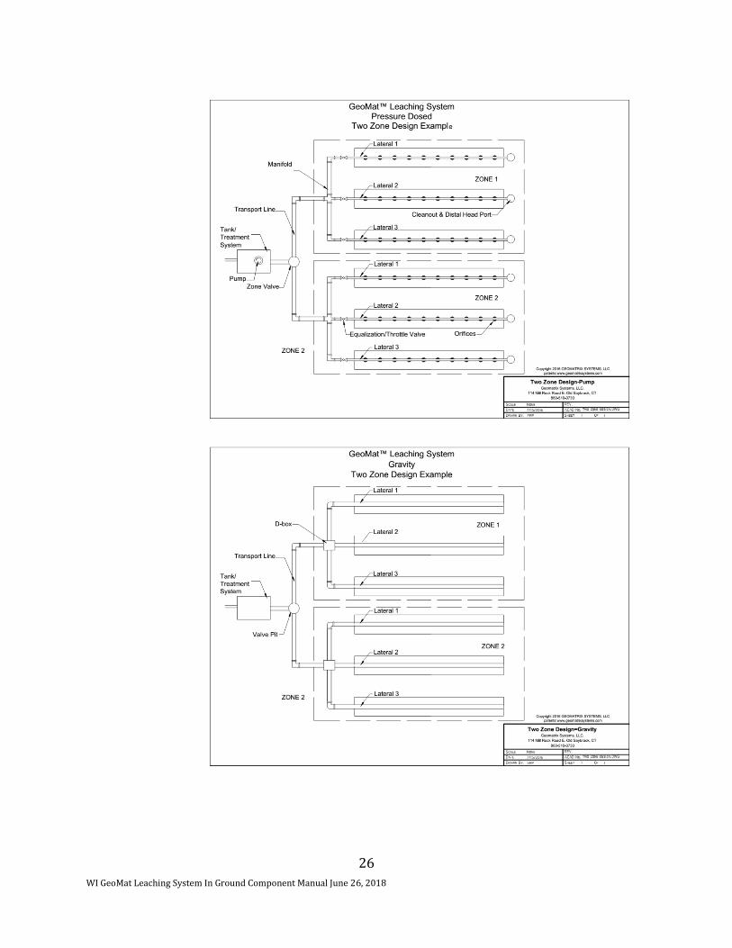
Distribution Network and Dosing Component
Uniform application of wastewater is critical, all systems must be parallel distribution. Gravity distribution boxes or level headers must be used. Use of high level overflow or serial distribution systems is prohibited. The effluent application to the distribution cell may be gravity or pressure. Distribution boxes or drop boxes may be used to distribute effluent to gravity feed distribution cells. Distribution piping for gravity component has a nominal inside diameter if 4 inches. The distribution header pipe is non perforated pipe. The slope of gravity flow perforated distribution piping is less than or equal to 1 inch per 100 feet away from distribution boxes, drop boxes or header. When a drop box design is used, the invert of the drop box overflow pipe must be at least 4 inches lower than the invert of the treatment tank outlet or force main connection.
The design and installation of distribution boxes must be watertight and capable of providing a means of providing equal distribution of effluent to each distribution cell. Drop boxes must be watertight and capable of distributing effluent to another distribution cell.
Components that are designed to receive a DWF greater than 1500 gal/day, dose the effluent to the distribution cell by means of a pump or siphon. The dose chamber shall contain sufficient volume to dose the distribution cell as required by its system design, retain drain back volume, contain a one day reserve zone, provide a minimum 2 inch separation between alarm activation and pump-on activation, and allow for protection of the pump from solids.
Drain back volumes can be calculated based on values listed in Table 5.

WI GeoMat Leaching System In Ground Component Manual June 26, 2018
21
A reserve capacity is required on a system with only one pump. The reserve volume must be equal to or greater than the estimated daily wastewater flow. Reserve capacity must be calculated using 100 gallons per bedroom per day for one and two family residences or the values computed by using Table 4.
The dose volume shall be included in the sizing of the dose chamber. (Volume of a septic tank effluent pump system is determined by department plumbing product approval.) The pump alarm activation point must be at least 2 inches above the pump activation point.
Allow “dead” space below the pump intake to permit settling of solids in the dose chamber. This can be accomplished by placing the pump on concrete blocks or other material that can form a pedestal.
The pump manufacturer’s requirement shall be followed. This may include the “pump off” switch being located high enough to allow for complete emersion of the pump in the dose chamber.
Observation pipes are installed in the sand portion of the distribution cells and are provided with a means of anchoring to prevent them from being lifted up. Observation pipes extend from the sand base to the point at or above the finished grade. The portion of the observation pipe below the distribution pipe is slotted while the portion above the distribution pipe is solid wall. Observation piping has a nominal pipe size of 4 inches. (See Figure 7)
VII. SITE PREPERATION AND CONSTRUCTION
Procedures used in the construction of an in-ground absorption component are just as critical as design of the component. A good design with poor construction results in component failure. It is emphasized that the soil only be worked when the moisture content is low to avoid compaction and smearing. Consequently, installations are made only when the soil is dry enough to prevent compaction and smearing of the infiltrative surface. The construction plan to be followed includes:
SBD-10705-P (N. 01/01; R. 10/12) Page 17 of 32
Distribution Network and Dosing Component
The effluent application to the distribution cell may be by gravity or pressure, and may consist of piping
or leaching chambers. Distribution boxes or drop boxes may be used to distribute effluent to gravity
feed distribution cells. Distribution piping for a gravity component has a nominal inside diameter of 4
inches. The distribution header is non perforated pipe. The slope of gravity flow perforated
distribution piping is less than or equal to 4 inches per 100 feet away from distribution boxes, drop
boxes or header. When a drop box design is used, the invert of the drop box overflow pipe must be at
least 4 inches lower than the invert of the treatment tank outlet or force main connection.
The design and installation of distribution boxes must be watertight and capable of providing a means
of providing equal distribution of effluent to each distribution cell. Drop boxes must be watertight and
capable of distributing effluent to another distribution cell.
Components that are designed to receive a DWF greater than 1500 gal/day, dose the effluent to the
distribution cell by means of a pump or siphon. The dose chamber shall contain sufficient volume to
dose the distribution cell as required by its system design, retain drain back volume, contain a one day
reserve zone, provide a minimum 2 inch separation between alarm activation and pump-on activation,
and allow for protection of the pump from solids.
Drain back volumes can be calculated based on values listed in Table 5.
Table 5
VOID VOLUME FOR VARIOUS DIAMETER PIPES
BASED ON NOMINAL I.D.a
Nominal Pipe Size Gallons per Foot
1-1/4 0.064
1-1/2 0.092
2 0.163
3 0.367
4 0.65
6 1.469
Note a: Table is based on - p(d/2)2 x 12”/ft ¸ 231 cu.in./cu.ft.
Where: d = nominal pipe size in inches
A reserve capacity is required on a system with only one pump. The reserve volume must be equal to
or greater than the estimated daily wastewater flow. Reserve capacity may be calculated using 100
gallons per bedroom per day for one and two family residences or the values computed by using Table
4.
The dose volume shall be included in the sizing of the dose chamber. (Volume of a septic tank effluent
pump system is determined by department plumbing product approval.)
The pump alarm activation point must be at least 2 inches above the pump activation point.

WI GeoMat Leaching System In Ground Component Manual June 26, 2018
22
A. Equipment – Proper equipment includes track machines or other equipment that will not compact the infiltrative surface. Minimize foot traffic on infiltrative surface and avoid equipment traffic on or over infiltrative surface.
B. Sanitary Permit – Prior to the construction of the component, a sanitary permit,
obtained for the installation, must be posted in a clearly visible location on the site. Arrangements for inspection(s) must also be made with the department or governing unit issuing the sanitary permit.
C. Construction Procedures
1. Check the moisture content and condition of the soil at system elevation and several inches below as needed. If the soil at the infiltrative surface can be rolled into a ¼ inch wire, the site is to wet, smearing and compaction will result, thus reducing the infiltrative capacity of the soil. If the site is too wet, do not proceed until it dries out. If the soil at or below the infiltrative surface is frozen, do not proceed.
2. Set up a construction level or similar device and determine all relative elevations in relationship to the benchmark. If it is necessary to determine the bottom elevation of the distribution cell, land surface contour lines, and appropriate component elevations critical to the installation.
3. Lay out the absorption area within the tested designated area. When possible
lay out the absorption area(s) on the site so that the distribution cell runs parallel with the land surface contours. Reference stakes offset from the corner stakes are recommended in case corner stakes are distributed during construction.
4. Excavate the infiltrative cell (basal area) + K dimension to the bottom elevation
(system elevation) taking care not to smear the infiltrative surface. If the infiltrative surface or sidewalls are smeared, loosen it up with the use of a rake or similar device. The infiltrative surface can be left rough and should not be raked smooth.
5. Place 12 inches of ASTM C33 sand on scarified non-compacted in situ soil that is
free of debris and rocks. This will be over the entire area required based on basal loading rate. Ensure trees and shrubs are removed within 10 feet of the GeoMat to prevent root intrusion. No Weeping Willow, Black Locust or similar aggressive rooting trees or plants shall be within 30 feet of the GeoMat. These separation distances can be minimized through use of root barriers. Please contact Geomatrix for assistance.
6. Place GeoMat on Sand fill. GeoMat to be 12 inches from end walls and equally
spaced from side wall depending on I dimension. See Formula 3.
7. Install observation pipes with the bottom 1 inch of the pipe slotted. Installation of the observation pipe includes a suitable means of anchoring so the pipes are not dislodged during inspections. Observation pipes will be installed in each distribution cell so as to be representative of a cell’s hydraulic performance.

WI GeoMat Leaching System In Ground Component Manual June 26, 2018
23
Observation pipes shall be located at least 4 feet from the end wall and sidewall; and be installed at an elevation to view the horizontal or level infiltrative surface within the dispersal cell. Use heavy utility knife to make cut outs for obs. pipes in GeoMat.
8. Place distribution pipes as determined from design, under fabric and on top of
GeoMat material. Connect the distribution box, drop box or header from the treatment or dosing tank.
9. Place cover material over fabric. Avoid cobbles, stones or frozen material that
could damage pipe, GeoMat, or fabric,
Figure 7 - Typical GeoMat Design Examples

WI GeoMat Leaching System In Ground Component Manual June 26, 2018
24

WI GeoMat Leaching System In Ground Component Manual June 26, 2018
25
WI GeoMat Leaching System In Ground Component Manual June 26, 2018
26

WI GeoMat Leaching System In Ground Component Manual June 26, 2018
27
VIII. GEOMAT IN GROUND WORKSHEET
A. SITE CONDITIONS Evaluate the site and soils for the following:
• Surface water movement. • Measure elevations and distances on the site so that slope, contours, and
available areas can be determined. • Determine the limiting conditions such as bedrock, high groundwater level, soil
application rates, and setbacks.
• Description of several soil profiles where the system will be located.
Slope - %
Occupancy – One or two-family dwelling: (number of bedrooms)
Public facility gallons per day (Estimated water flow)
Depth to limiting factor inches
Minimum depth of unsaturated soil required by table 383.44-3, Wis. Adm. Code 24 inches
In Situ Soil application rate of in situ soil used gal/sq.ft. /day
FOG value of effluent applied to component ≤ 20 mg/L
BOD5 value of effluent applied to component ≤ 180 mg/L
TSS value of effluent tied to component ≤ 50 mg/L
Fecal coliform monthly geometric mean value of effluent tied to component ≥ 10⁴ CFU
/100mg
X Yes __________ No
Type of Dist. Cell---GeoMat
B. DESIGN WASTEWATER FLOW
One and two-family dwelling
Combined wastewater flow:
DWF = 150 gal/day/ bedroom x number of bedrooms

WI GeoMat Leaching System In Ground Component Manual June 26, 2018
28
= 150 gal/day/bedroom x # of bedrooms
= 150 gal/day/bedroom x ____________bedrooms = _______ gal/day
Clearwater and greywater only:
DWF = 90 gal/day/bedroom x # of bedrooms = 90 gal/day/bedroom x __________ # of bedrooms = _______gal/day
Blackwater only:
DWF = 60 gal/day/bedroom x # of bedrooms = 60 gal/day/bedroom x __________ # of bedrooms = _______gal/day Public Facilities DWF = Estimated wastewater flow x 1.5 = __________ gal/day x 1.5 = __________ gal/day
C. WIDTH AND LENGTH OF THE DISTRIBUTION CELL
1. Determine the Design Loading Rate (DLR) for the site. From Table 383.44-2, WI Adm Code, select the soil application rate for the most restrictive soil horizon at the infiltrative surface or a lower horizon of the the lower horixz=zon adversely affects the dispersal of wastewater in accordance with SPS 383.44 (4) (a) and (c). The Design Loading Rate (DLR) is the soil application rate taken from Table 383.44-2 WI adm Code. DLR = __________ gpd/ ft2
2. Determine the Infiltrative basal area.
Calculate the distribution cell area by dividing the daily Design Wastewater Flow (DWF) by the Design Loading Rate (DLR).

WI GeoMat Leaching System In Ground Component Manual June 26, 2018
29
Infiltrative basal area = DWF ÷ DLR Infiltrative basal area = __________ gpd ÷ ____________ gpd/ft2
Infiltrative basal area = ____________ ft2
3. Determine size of distribution cell
Loading rate of fill material = ≤ 1.0 gal/sq.ft./day if BOD5 or TSS ≥ 30 mg/L
or = _ ≤ 2.0 gal/sq.ft./day if BOD5 or TSS ≤30 mg
or = _ ≤ 2.2 gal/sq.ft./day if BOD5 or TSS ≤30 mg/L & 1.6 gal/sq ft/ day soil application rate
b. Bottom area of distribution cell = Design wastewater flow ÷loading rate of fill material as determined in C.1 a. Distribution cell area = ______ gal/day÷ _____ gal/ft²./day Distribution cell area = ______ ft²
4. Distribution Cell Configuration
a. Distribution cell width(s) (A) = 3.25 feet and the number of distribution cells = ____ cells. b. Distribution cell length (B) = Bottom area of distribution cell ÷ width of distribution cell. B = ______ ft². ÷ (Distribution cell area required) ÷ _______ ft. (A) B = _______ or _____ ft c. Check distribution cell length (B)
5. Basal Area calculation Basal Area required = (Cell length) *[((3.25 * # Cells) + (2I) + (cell spacing * # cells-1))]
If only 1 cell: Basal Area = (Cell length) *[((3.25 * # Cells) + (2I) If more than 1 cell is to be used: In this application all numbers are known except cell spacing. Use Formula 3 to solve for cell spacing:
Formula 3 Cell Spacing = [(Basal area needed ÷ cell length)] - [(Cell Width * # Cells) +2I]
(# cells -1) Basal area is known Cell length is known

WI GeoMat Leaching System In Ground Component Manual June 26, 2018
30
Cell width is known # cells is known I dimension is 1foot
Cell spacing(S) = __________ feet minimum S dimension is 1 foot
Now that S is Known:
Basal Area required = (Cell length) *[((3.25 * # Cells) + (2I) + (cell spacing * # cells-1))]
If only 1 cell: Basal Area = (Cell length) *[((3.25 * # Cells) + (2I) Basal Area = __________ Sq FT Check basal area ________ proposed, _________ required
6. Total Length and Width (L X W) L = Cell length + 2K K is always 1 L = ______ feet
W = (Cell width * # Cells) + 2I + (Cell spacing * (# Cells -1)) W = ________ feet
7. Linear loading rate Linear loading rate ≤ Design wastewater flow ÷ Cell length (B) or effective cell length. Linear loading rate ≤ _____ gal/day ÷ _______ feet Linear loading rate ≤ _______ gal/ft/day Linear loading rate for systems with in situ soils having a soil application rate of ≤ 0.3 gal/ ft²/day within 12 inches of original grade must be less than or equal to 4.5 gal/ft/day.
Is the linear loading rate ≤ what is allowed? ___ Yes ____ No -----If no, then the length and width of the distribution cell must be changed so it does. Distribution cell length B = Design Wastewater Flow ÷ Maximum Linear Loading Rate Distribution cell length B = _____ gal/day ÷ _____ gal/ft/day Distribution cell length B = _________ ft.

WI GeoMat Leaching System In Ground Component Manual June 26, 2018
31
IX. GEOMAT IN-GROUND WORKSHEET EXAMPLE
A. SITE CONDITIONS Evaluate the site and soils for the following:
• Surface water movement. • Measure elevations and distances on the site so that slope, contours, and
available areas can be determined. • Determine the limiting conditions such as bedrock, high groundwater level, soil
application rates, and setbacks. • Description of several soil profiles where the system will be located.
Slope - %
Occupancy – One or two-family dwelling: 5 (number of bedrooms)
Public facility gallons per day 0 (Estimated water flow)
Depth to limiting factor 70 inches
Minimum depth of unsaturated soil required by table 383.44-3, Wis. Adm. Code 24 inches
In Situ Soil application rate of in situ soil used 1.6 gal/sq.ft. /day
FOG value of effluent applied to component ≤ 20 mg/L
BOD5 value of effluent applied to component ≤ 180 mg/L
TSS value of effluent tied to component ≤ 50 mg/L
Fecal coliform monthly geometric mean value of effluent tied to component ≥ 10⁴ CFU /100mg
X Yes __________ No
Type of Dist. Cell---GeoMat
B. DESIGN WASTEWATER FLOW
One and two-family dwelling
Combined wastewater flow:
DWF = 150 gal/day/ bedroom x number of bedrooms

WI GeoMat Leaching System In Ground Component Manual June 26, 2018
32
= 150 gal/day/bedroom x # of bedrooms
= 150 gal/day/bedroom x _____5_______bedrooms = 750 gal/day
Clearwater and greywater only:
DWF = 90 gal/day/bedroom x # of bedrooms = 90 gal/day/bedroom x __________ # of bedrooms = gal/day
Blackwater only:
DWF = 60 gal/day/bedroom x # of bedrooms = 60 gal/day/bedroom x __________ # of bedrooms = gal/day Public Facilities DWF = Estimated wastewater flow x 1.5 = __________ gal/day x 1.5 = __________ gal/day
C. WIDTH AND LENGTH OF THE DISTRIBUTION CELL
8. Determine the Design Loading Rate (DLR) for the site. From Table 383.44-2, WI Adm Code, select the soil application rate for the most restrictive soil horizon at the infiltrative surface or a lower horizon of the the lower horixz=zon adversely affects the dispersal of wastewater in accordance with SPS 383.44 (4) (a) and (c). The Design Loading Rate (DLR) is the soil application rate taken form Table 383.44-2 WI adm Code. DLR = ______1.6____ gpd/ ft2
9. Determine the Infiltrative basal area.
Calculate the distribution cell area by dividing the daily Design Wastewater Flow (DWF) by the Design Loading Rate (DLR). Infiltrative basal area = DWF ÷ DLR

WI GeoMat Leaching System In Ground Component Manual June 26, 2018
33
Infiltrative basal area = ___750_______ gpd ÷ _____1.6_______ gpd/ft2
Infiltrative basal area = _____469_______ ft2
10. Determine size of distribution cell Loading rate of fill material = ≤ 1.0 gal/sq.ft./day if BOD5 or TSS ≥ 30 mg/L or = _ ≤ 2.0 gal/sq.ft./day if BOD5 or TSS ≤30 mg
= X ≤ 2.2 gal/sq.ft./day if BOD5 or TSS ≤30 mg/L & 1.6 gal/sq ft/ day soil application rate
b. Bottom area of distribution cell = Design wastewater flow ÷loading rate of fill material as determined in C.1 a. Distribution cell area = 750 gal/day÷ 2.2 gal/ft²./day Distribution cell area = 341 ft²
11. Distribution Cell Configuration
OPTIONS—3.25 feet
a. Distribution cell width(s) (A) = 3.25 feet and the number of distribution cells = 2 cells. b. Distribution cell length (B) = Bottom area of distribution cell ÷ width of distribution cell. B = 341 ft². ÷ (Distribution cell area required) ÷ 6.50 ft. (A) B = 52.44 or 53 ft c. Check distribution cell length (B)
12. Basal Area calculation Basal Area required = (Cell length) *[((3.25 * # Cells) + (2I) + (cell spacing * # cells-1))]
If only 1 cell: Basal Area = (Cell length) *[((3.25 * # Cells) + (2I) If more than 1 cell is to be used: In this application all numbers are known except cell spacing. Use Formula 3 to solve for cell spacing:
Formula 3 Cell Spacing = [(Basal area needed ÷ cell length)] - [(Cell Width * # Cells) +2I]
(# cells -1) Basal area is known Cell length is known

WI GeoMat Leaching System In Ground Component Manual June 26, 2018
34
Cell width is known # cells is known ** I dimension is 1 foot Cell Spacing (S) = [(469÷53)] - [(3.25 * #2) +2] (2 -1) Cell Spacing (S) = [(8.85)] - [(6.5) +2] (1) Cell Spacing(S) = [(8.85)] - [(6.5) +2] (1)
Cell spacing(S) = .35 feet minimum S dimension is 1 foot
Now that S is known:
Basal Area required = (Cell length) *[((3.25 * # Cells) + (2I) + (cell spacing * # cells-1))]
If only 1 cell: Basal Area = (Cell length) *[((3.25 * # Cells) + (2I) Basal Area = (53) * [((3.25 * # 2) + (2I) + (1* # 2-1))]
= (53) * (6.5 ) + (2) +( 1) = (53) * (9.5) = 503.5 Sq FT Check basal area 503.5 proposed, 469 required
13. Total Length and Width (L X W)
L = Cell length + 2K K is always 1 L = 53 + 2 L = 55 feet W = (Cell width * # Cells) + 2I + (Cell spacing * (# Cells -1)) W = 3.25 * 2 + (2*1) +(1* (2-1)) W = 6.5 feet + 2 + 1 W = 9.5 feet
14. Linear loading rate
Linear loading rate ≤ Design wastewater flow ÷ Cell length (B) or effective cell length. Linear loading rate ≤ 750 gal/day ÷ 53 feet Linear loading rate ≤ 14 gal/ft/day Linear loading rate for systems with in situ soils having a soil application rate of ≤ 0.3 gal/ ft²/day within 12 inches of original grade must be less than or equal to 4.5 gal/ft/day.
Is the linear loading rate ≤ what is allowed? _X Yes ____ No -----If no, then the length and width of the distribution cell must be changed so it does.

WI GeoMat Leaching System In Ground Component Manual June 26, 2018
35
Distribution cell length B = Design Wastewater Flow ÷ Maximum Linear Loading Rate Distribution cell length B = _____ gal/day ÷ _____ gal/ft/day Distribution cell length B = _________ ft.
X. GEOMAT IN-GROUND PLAN SUBMITTAL A. Plan Submittal
Submit Plan File.
In addition to the Plan File, the following information is required to be submitted for review: • Photocopies of soil report forms along with other documents required by the
reviewing agent.
• Plans or documents must be originals or permanent copies.
B. Forms and Fees • Application form for submittal provided by the reviewing agent, along with
proper fees required by the reviewing agent.
C. Soils Information • Complete soil and site evaluation report (Form # SBD-8330) for each soil boring
described; signed and dated by Certified Soil Tester, with License Number.
• Separate sheet showing the location of all borings. The location of all boring and backhoe pits must be able to be identified on the plot plan.
D. Documentation
• Architects, engineers, or designers must sign, seal, and date each page of the submittal or provide an index page, which is signed, sealed, and dated.
• Mater Plumbers must sign, date, and include their license number on each page of the submittal or provide an index page, which is signed, sealed, and dated.
• Three complete sets of plans and specifications (clear, permanent, and legible);
submittals must be on paper measuring at least 8.5 x 11 inches.
• Designs
E. Plot Plan • Document plans or plans drawn to scale (scale indicated on plans) with parcel
size or all property boundaries. Clearly marked.
• Slope directions and percent in system area.
• Benchmark and north arrow.
• Setbacks indicated as per appropriate code.

WI GeoMat Leaching System In Ground Component Manual June 26, 2018
36
• Two-foot contours or other appropriate contour interval within the system area.
• Location information, legal description of parcel must be noted. • Location of any nearby system or well.
F. Plan View
• Dimensions for distribution cells
• Location of observation pipes.
• Dimensions of trench.
• Pipe lateral layout, which must include the number of laterals, pipe material, diameter and length; and number, location and size of orifices.
• Manifold and force main locations, with materials, length and diameter of each.
G. Cross Section of System
• Include tilling requirement, distribution cell details, percent slope, side slope, and cover material.
• Lateral elevation, position of observation pipes, dimensions of distribution cell,
and type of cover material such as filter fabric, if applicable.
H. System Sizing • For one and two-family dwellings, the number of bedrooms must be included.
• For public buildings, the sizing calculations must be included.
I. Tank and Pump or Siphon Information
• All construction details for site-construction tanks.
• Size and manufacturer information for prefabricated tanks.
• Notation of pump or siphon model, pump performance curve, friction loss for force main and calculation for total dynamic head.
• Notation of highwater alarm manufacturer and model number.
• Cross section of dose tank / chamber to include storage volumes; connections
for piping, vents, and power; pump “off” setting; dosing cycle and volume, highwater alarm setting; and storage volume above the highwater alarm; and location of vent and manhole.
• Cross section of two compartment tanks or tanks installed in a series must
include information listed above.

WI GeoMat Leaching System In Ground Component Manual June 26, 2018
37


![“Experiencia y calidad” - [GEOMAT Ingenería] - … DE CIERRE DE MINAS INGENIERÍA DE PROYECTOS MULTIDISCIPLINARIOS GEOMAT INGENIERIA cuenta con la capacidad técnica y organizativa](https://img.dokumen.tips/doc/110x75/5ba902fb09d3f2fb228bc5c1/experiencia-y-calidad-geomat-ingeneria-de-cierre-de-minas-ingenieria.jpg)