Embed Size (px)
Citation preview
i
ENZYME IMMOBILIZATION ON TITANIA-SILICA-GOLD THIN FILMS FOR BIOSENSOR APPLICATIONS AND PHOTOCATALYTIC ENZYME
REMOVAL FOR SURFACE PATTERNING
A THESIS SUBMITTED TO THE GRADUATE SCHOOL OF NATURAL AND APPLIED SCIENCES
OF MIDDLE EAST TECHNICAL UNIVERSITY
BY
MERVE ÇINAR
IN PARTIAL FULFILLMENT OF THE REQUIREMENTS FOR
THE DEGREE OF MASTER OF SCIENCE IN
CHEMICAL ENGINEERING
SEPTEMBER 2009
ii
Approval of the thesis:
ENZYME IMMOBILIZATION ON TITANIA-SILICA-GOLD THIN FILMS FOR BIOSENSOR APPLICATIONS AND PHOTOCATALYTIC ENZYME
REMOVAL FOR SURFACE PATTERNING
submitted by MERVE ÇINAR in partial fulfillment of the requirements for the degree of Master of Science in Chemical Engineering Department, Middle East Technical University by, Prof. Dr. Canan Özgen ________________ Dean, Graduate School of Natural and Applied Sciences Prof. Dr. Gürkan Karakaş ________________ Head of Department, Chemical Engineering Prof. Dr. Ufuk Bakır ________________ Supervisor, Chemical Engineering Dept., METU Prof. Dr. Gürkan Karakaş ________________ Co-supervisor, Chemical Engineering Dept., METU Examining Committee Members: Prof. Dr. Deniz Üner ________________ Chemical Engineering Dept., METU Prof. Dr. Ufuk Bakır ________________ Chemical Engineering Dept., METU Prof. Dr. Gürkan Karakaş ________________ Chemical Engineering Dept., METU Prof. Dr. Mehmet Mutlu ________________ Food Engineering Dept., HÜ Prof. Dr. Zümrüt B. Ögel ________________ Food Engineering Dept., METU Date: 17.09.2009

iii
I hereby declare that all information in this document has been obtained and presented in accordance with academic rules and ethical conduct. I also declare that, as required by these rules and conduct, I have fully cited and referenced all material and results that are not original to this work.
Name, Last Name: Merve Çınar Signature:
iv
ABSTRACT
ENZYME IMMOBILIZATION ON TITANIA-SILICA-GOLD THIN FILMS
FOR BIOSENSOR APPLICATIONS AND PHOTOCATALYTIC ENZYME
REMOVAL FOR SURFACE PATTERNING
Çınar, Merve
M.S., Department of Chemical Engineering
Supervisor : Prof. Dr. Ufuk Bakır
Co-supervisor: Prof.Dr. Gürkan Karakaş
September 2009, 75 pages
The aim of this study was to investigate the viability of patterning by
immobilization, photocatalytic removal, and re-immobilization steps of the enzyme
on photocatalytically active thin films for biosensor fabrication purposes. For this
aim, TiO2-SiO2-Au sol-gel colloids were synthesized and deposited on glass
substrates as thin films by dip coating. Cysteamine linker was assembled on gold
nanoparticles to functionalize thin films with amine groups for immobilization of
model enzyme invertase. Effect of immobilization temperature, enzyme
concentration of the immobilization solution and immobilization period on
invertase immobilization were investigated. The immobilized invertase activity was
found independent from the immobilization temperature in the range tested (4oC-
room temperature). The optimum enzyme concentration and period for
immobilization was determined as 10µg/ml and 12 hours respectively. The
resulting invertase immobilized thin films showed high storage stability retaining
more that 50% of their initial activity after 9 weeks of storage.
v
Photocatalytic enzyme removal and re-immobilization studies were carried out by
irradiating the invertase immobilized thin films with blacklight. Upon 30 minutes
of irradiation, immobilized invertase was completely and irreversibly inactivated.
Initial immobilized invertase activity (before the irradiation) was attained when
invertase was re-immobilized on thin films that were irradiated for 5 hours. Thus it
was inferred that with sufficient exposure, enzymes can be completely removed
from the surfaces which makes the re-immobilization possible. The possibility of
enzyme removal with photocatalytic activity and re-immobilization can pave the
way to new patterning techniques to produce multi-enzyme electrode arrays.
Keywords: TiO2, SiO2, Au, photocatalysis, thin films, sol-gel, patterning,
invertase, immobilization, biosensor
vi
ÖZ
BİYOSENSÖR UYGULAMALARI İÇİN TİTANYUM DİOKSİT-SİLİKON
DİOKSİT-ALTIN İNCE FİLMLERE ENZİM İMMOBİLİZASYONU VE
FOTOKATALİTİK ENZİM UZAKLAŞTIRILMASI İLE YÜZEY
DESENLENMESİ
Çınar, Merve
Yüksek Lisans, Kimya Mühendisliği Bölümü
Tez Yöneticisi : Prof. Dr. Ufuk Bakır
Tez Eş-Yöneticisi: Prof. Dr. Gürkan Karakaş
Eylül 2009, 75 sayfa
Bu çalışmada, biyosensör uygulamaları için fotokatalitik aktif yüzeylere enzim
tutuklanması, enzimin fotokatalitik olarak yüzeyden uzaklaştırılması ve tekrar
yüzeye tutuklanması ile desenlemenin uygulanabilirliği araştırılmıştır. Bu amaçla,
TiO2-SiO2-Au sol-jel kolloid çözeltileri cam yüzeylere ince filmler halinde
kaplanmıştır. Sentezlenen ince filmler, sisteamin bağlayıcısının altın nanotanecikler
üzerinde kendinden düzenlenmesiyle amin fonksiyonelleştirilmiş ve invertaz
tutuklanması sağlanmıştur. Tutuklama sıcaklığının, tutuklama çözeltisi enzim
konsantrasyonunun ve tutuklama süresinin, tutuklanan invertaz aktivitesine etkisi
araştırılmıştır. Tutuklanan invertaz aktivitesinin denenen sıcaklık aralığında (4oC-
oda sıcaklığı) tutuklama sıcaklığından bağımsız olduğu görülmüştür. Optimum
enzim konsantrasyonu ve süresi sırasıyla 10µg/ml ve 12 saat olarak bulunmuştur.
Invertaz tutuklanmış enzim yüzeyleri 9 hafta bekleme süresinden sonra ilk
vii
aktivitelerinin 50% den fazlasını korumuş ve yüksek saklama kararlılığı
göstermiştir.
Fotokatalitik enzim uzaklaştırması ve tekrar tutuklanması çalışmaları, invertaz
tutuklanmış yüzeylerin siyah ışığa (368 nm.) tutulması ile yürütülmüştür. 30 dakika
ışığa maruz kalan ince filmlere tutuklanmış invertaz tamamen ve geri dönüşümsüz
olarak inaktive edilmiştir. Tutuklanan invertazın başlangıç aktivitesine (siyah ışığa
maruz kalmadan önce) 5 saat ışığa maruz kalan yüzeylere tekrar enzim
tutuklandığında ulaşılmıştır. Böylece ışığa yeterli süreyle maruz kalan enzimlerin
tamamen yüzeyden kaldırılabileceği görülmüş ve tekrar enzim tutuklanması
sağlanmıştır. Fotokatalitik aktivite ile enzimlerin yüzeylerden uzaklaştırılması ve
tekrar yüzeye tutuklanması olasılığı, çoklu enzim elektrot arrayleri yapımında
kullanılabilecek yeni bir desenleme tekniğine zemin hazırlamıştır.
Anahtar Kelimeler: TiO2, SiO2, Au, fotokataliz, ince film, sol-jel, desenleme,
invertaz, tutuklama, biyosensör

viii
To my family,

ix
ACKNOWLEDGEMENTS
First and foremost, I would like to express my deepest and sincere gratitude to my
thesis supervisor, Prof. Dr. Ufuk Bakır for her valuable and encouraging guidance
and supervision throughout this study.
I am also grateful to my co-supervisor Prof. Dr. Gürkan Karakaş for his guidance.
His wide knowledge has been of great value to me.
I would like to thank all my friends in Industrial Biotechnology and Environmental
Catalysis Laboratory; Eda Açık, Serpil Apaydın, Erinç Bahçegül, Eda Bayraktar,
Bilal Bayram,Umut Çekmez, Zeynep Eker, Beril Korkmaz Erdural, İrfan Ersöz,
Aytaç Kocabaş, Didem Sutay Kocabaş, Gizem Seber, Esra Uçkun, Pelin
Yetişemiyen and Alp Yürüm. I will always appreciate to be part of a welcoming,
friendly, and helpful group. I am especially grateful to Zeynep Eker for her
invaluable friendship and cordiality throughout this study.
I want to extend my appreciation to my all friends who made my undergraduate
and graduate years in METU enjoyable and memorable contributing directly or
indirectly towards making this study possible.
Scientific and Technological Research Council of Turkey (TÜBİTAK) is also
gratefully acknowledged for providing financial means throughout this study.
Finally, I would like to express my deepest gratitude to my family for their
unconditional love, support, encouragement and patience throughout my life. I
have always felt the privilege of having such a family.
x
TABLE OF CONTENTS
ABSTRACT .........................................................................................................iv
ÖZ ........................................................................................................................vi ACKNOWLEDGEMENTS ..................................................................................ix
LIST OF FIGURES ........................................................................................... xiii LIST OF TABLES .............................................................................................. xvi CHAPTERS 1. INTRODUCTION .......................................................................................... 1
2. LITERATURE SURVEY ............................................................................... 3
2.1 Biosensors ............................................................................................... 3
2.1.1 Enzyme Biosensors: General Concept ............................................... 4
2.1.2 Application of Nanoparticles in Biosensors ....................................... 5
2.2 Gold Nanoparticles .................................................................................. 6
2.2.1 Enhancement of electron transfer ...................................................... 6
2.2.2 Self-assembled monolayers ............................................................... 7
2.3 Titanium dioxide ...................................................................................... 9
2.3.1 Photocatalysis ................................................................................. 10
2.4 Thin Films Synthesis .............................................................................. 12
2.4.1 Sol-gel processing ........................................................................... 13
2.4.2 Coating Techniques ........................................................................ 14
2.5 Enzymes ................................................................................................ 16
2.5.1. Invertase ......................................................................................... 17
2.6 Immobilization of enzymes .................................................................... 19
2.6.1 Adsorption ...................................................................................... 19
2.6.2 Covalent binding ............................................................................. 20
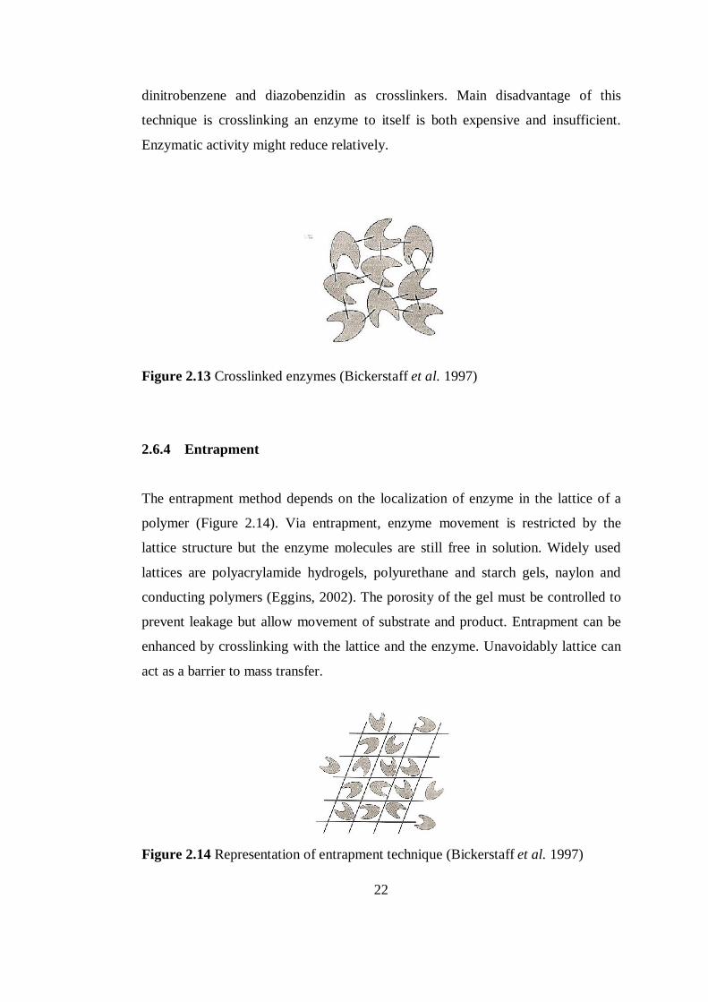
2.6.3 Crosslinking.................................................................................... 21
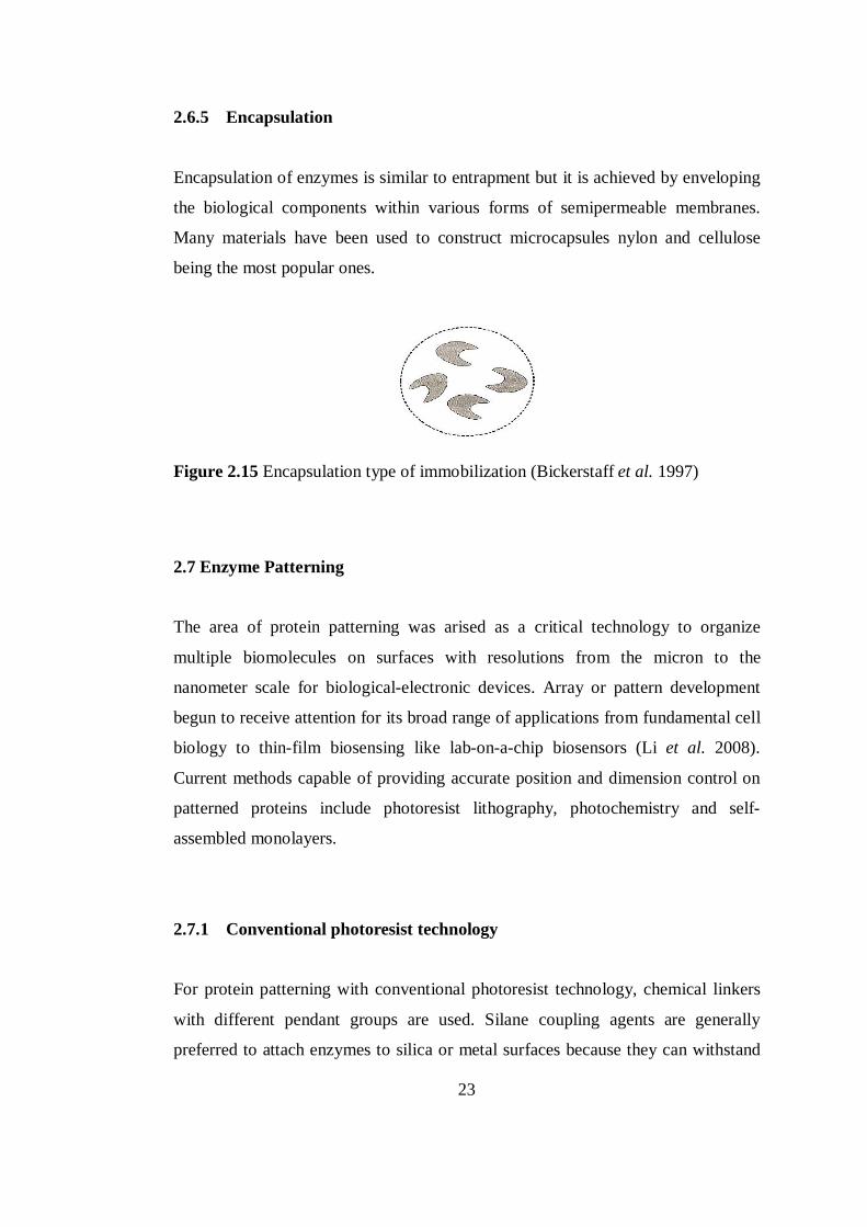
2.6.4 Entrapment ..................................................................................... 22
2.6.5 Encapsulation ................................................................................. 23
2.7 Enzyme Patterning ................................................................................. 23
2.7.1 Conventional photoresist technology ............................................... 23
2.7.2 Photochemical techniques ............................................................... 24
2.7.3 Self Assembled Monolayers ............................................................ 26
xi
3. MATERIALS AND METHODS .................................................................. 28
3.1 Materials ................................................................................................ 28
3.2 Preparation of thin film coatings ............................................................ 28
3.2.1 Pretreatment of glass substrates ....................................................... 28
3.2.2 Synthesis of colloidal solution......................................................... 29
3.2.3 Dip-coating of glass substrates ........................................................ 29
3.3 AFM Characterization ............................................................................ 30
3.4 SEM Analysis ........................................................................................ 31
3.5 Immobilization studies ........................................................................... 31
3.5.1 Linker deposition ............................................................................ 31
3.5.2 Immobilization of invertase............................................................. 31
3.5.3 Invertase activity measurements ...................................................... 32
3.5.4 Effect of temperature on immobilized invertase activity .................. 34
3.5.5 Effect of enzyme concentration on immobilization .......................... 34
3.5.6 Effect of enzyme immobilization period on immobilization ............ 35
3.5.7 Storage stability determination of immobilized invertase ................ 35
3.6 Photocatalyzed enzyme inactivation and removal from thin films .......... 36
3.6.1 Irradiation of free invertase ............................................................. 36
3.6.2 Irradiation of invertase immobilized thin films ................................ 36
3.6.3 Reimmobilization of invertase to the irradiated thin films ............... 37
3.6.4 Determination of irradiation exposure time ..................................... 37
4. RESULTS AND DISCUSSION ................................................................... 38
4.1 Thin Film Synthesis ............................................................................... 38
4.1.1 AFM characterization of thin films ................................................. 41
4.1.2 SEM Analysis of thin films ............................................................. 42
4.2 Enzyme immobilization ......................................................................... 43
4.2.1 SEM Analysis of enzyme immobilized thin films ............................ 45
4.3 Optimization of enzyme immobilization conditions................................ 47
4.3.1 Effect of calcination period on enzyme immobilization ................... 47
4.3.2 Effect of immobilization temperature on enzyme immobilization .... 49
4.3.3 Effect of enzyme concentration of the immobilization solution on enzyme immobilization ................................................................................ 50
4.3.4 Effect of enzyme immobilization period on enzyme immobilization51
4.4 Storage stability of invertase immobilized thin films .............................. 53
xii
4.5 Investigation of TiO2 based photocatalytic immobilized enzyme removal ...................................................................................................................54
4.5.1 Effect of irradiation on free enzyme ................................................ 55
4.5.2 Blacklight induced photocatalytic effects on immobilized enzyme .. 57
4.5.3 Enzyme re-immobilization on irradiated thin films .......................... 59
5. CONCLUSIONS ........................................................................................... 63
REFERENCES .................................................................................................... 64 APPENDICES A. SPECIFICATIONS OF LUDOX SM-30 ...................................................... 72
B. DNSA METHOD FOR REDUCING SUGAR DETERMINATION ............. 73
C. GLUCOSE STANDART CURVE ............................................................... 74
D. EDX ANALYSIS OF TiO2-SiO2-Au THIN FILMS ...................................... 75
xiii
LIST OF FIGURES
Figure 2.1 Schematics of biosensor classification ................................................... 4
Figure 2.2 A representation of a mediated amperometric biosensor ........................ 5
Figure 2.3 Assembly of AuNP-reconstituted GOx electrode .................................. 7
Figure 2.4 Skeleton structure of cysteamine (amine and thiol functional groups) .... 8
Figure 2.5 Illustration of the major processes occurring on a semiconductor
photocatalyst following electronic excitation ........................................................ 10
Figure 2.6 Typical sol-gel processing routes ......................................................... 13
Figure 2.7 Types of coating techniques ................................................................ 15
Figure 2.8 Steps of dipcoating; immersion, start-up, deposition, drainage and
evaporation, respectively ...................................................................................... 16
Figure 2.9 General structure of an amino acid ...................................................... 17
Figure 2.10 Sucrose hydrolysis catalyzed by invertase ......................................... 18
Figure 2.11 Adsorption of enzymes with ionic binding ......................................... 20
Figure 2.12 Representation of covalent binding ................................................... 20
Figure 2.13 Crosslinked enzymes ........................................................................ 22
Figure 2.14 Representation of entrapment technique ............................................ 22
Figure 2.15 Encapsulation type of immobilization ................................................ 23
Figure 2.16 Photoresist technique applied to silane SAM’s .................................. 24
Figure 2.17 Photochemical patterning.. ................................................................ 25
xiv
Figure 3.2 Dip-coating equipment...........................................................................30 Figure 4.1 AFM images of (a) pre-treated glass substrate, (b) corresponding 3-D
view; (c) TiO2-SiO2-Au thin film, (d) corresponding 3-D view ............................. 41
Figure 4.2 SEM images of TiO2-SiO2-Au thin films with x2000 magnification .... 42
Figure 4.3 SEM images of TiO2-SiO2-Au thin films with x250000 magnification 43
Figure 4.4 Immobilization of invertase on cysteamine and TiO2-SiO2-Au thin film
assembly .............................................................................................................. 44
Figure 4.5 Reaction progress curves showing the termination of enzymatic reaction
with the removal of invertase immobilized thin film coated glass substrates (assay
conditions at 40oC, pH 5.0; 0.145 M sucrose concentration) ................................. 45
Figure 4.6 SEM images of TiO2-SiO2-Au thin films with x2000 magnification ... 46
Figure 4.7 SEM images of invertase immobilized TiO2-SiO2-Au thin films with
x2000 magnification. ........................................................................................... 46
Figure 4.8 Effect of calcination duration on reaction progress curves of
immobilized invertase (assay conditions at 40oC, pH 5.0, 0.145 M sucrose) ......... 48
Figure 4.9 Reaction progress curves for invertase, immobilized at room
temperature and 4oC (assay conditions at 40oC, pH 5.0, 0.145 M sucrose) ............ 49
Figure 4.10 Effect of enzyme concentration on immobilized invertase activity ..... 51
Figure 4.11 Effect of immobilization period on immobilized enzyme activity. ..... 52
Figure 4.12 Residual activity of immobilized invertase with respect to storage time
............................................................................................................................ 53
Figure 4.13 Reaction progress curves for UV-C irradiated free invertase (assay
conditions at 40oC, pH 5.0, 0.145 M sucrose) ....................................................... 56
xv
Figure 4.14 Reaction progress curves for blacklight irradiated free invertase (assay
conditions at 40oC, pH 5.0, 0.145 M sucrose) ....................................................... 56
Figure 4.15 Reaction progress curves of blacklight irradiated immobilized invertase
on TiO2-SiO2-Au thin films (assay conditions at 40oC, pH 5.0; 0.145 M sucrose) . 58
Figure 4.16 Reaction progress curves of irradiated immobilized invertase after
storage (assay conditions at 40oC and pH 5.0, 0.145 M sucrose) ........................... 59
Figure 4.17 Re-immobilized invertase activity on irradiated surfaces with
corresponding irradiation time .............................................................................. 60
Figure 4.18 Possible steps for patterning with the use of photocatalysis................ 62
Figure C.1 Representative glucose standart curve ................................................. 74
Figure D.1 EDX analysis of TiO2-SiO2 thin films...................................................75
xvi
LIST OF TABLES
Table 2.1 Different functions of nanoparticles in sensing ....................................... 6
Table 2.2 Band gap energies of rutile and anatase phases ..................................... 11
Table 2.3 Typical covalent coupling reactions for immobilization.........................21
Table 4.1 Apparent activities of the immobilized invertase on thin films with
respective calcination duration ............................................................................. 48
Table 4.2 Residual enzymatic activities of free invertae solution after irradiation . 57
Table 4.3 Residual immobilized enzyme activities after irradiation ...................... 58
Table B.1 Chemicals and relative amounts for DNSA reagent .............................. 73
Table C.1 Concentrations of the glucose solutions for glucose standart curve.......74
1
CHAPTER 1
1. INTRODUCTION
In general terms, sensor is a device that is able to detect a certain substance and
produce a measurable signal. When a biological component (which is usually
called as bioreceptor) is present in the recognition site, the sensor is called a
biosensor. Performance of biosensors can be improved by using nanomaterials in
their construction (Jianrong et al. 2004). When diffusional effects are also
considered for the performance of biosensor, it follows that the thinner the sensing
layer is, the less time this will take and thereby, speed and reversibility of sensor
response, may well be improved (Davis et al. 2005). Sol-gel type chemical solution
deposition technique is a highly flexible method for the fabrication of thin films
(Schwartz et al. 2004) and it is easy to prepare multicomponent structures to
introduce desired properties to the supports on which immobilization is achieved.
Sol-gel derived TiO2-SiO2 thin films can be used for the immobilization of
biomolecules due to their biocompatibility and high surface area.
Considerable attention is devoted to immobilization of enzymes. While all
biosensors are more or less selective for a particular analyte, enzyme biosensors
represent higher selectivity and specificity for their analytes (Thevenot et al. 2001).
Enzymes can be immobilized by several techniques. The method for
immobilization mainly depends on the type of biosensor, nature of the support and
enzyme, required stability and reusability. Covalent immobilization has the
advantage of stable coupling although being a complex method.
Covalent immobilization of enzymes to conductive or semiconductive supports can
be achieved by the availability of functional groups on the surface of the support.
2
Inherent surface functions, the monolayers assembled or other functional
modifications allow covalent coupling. One of the most commonly used coupling
chemistry is carbodiimide chemistry where amine functional groups are introduced
to support for coupling with carboxyl group of enzymes (Eggins, 2002).
Covalent coupling of enzymes is also necessary for gradient formation in order to
achieve control of enzyme location (Vepari et al. 2006). Patterns of enzymes
receive interest because parallel testing systems and multisensing for several
analytes can be reached with biosensor arrays. To control protein patterning on
surfaces there are several methods like photolithography and patterning of
monolayers (Reichert et al. 1998).
Here, model enzyme invertase was immobilized on TiO2-SiO2-Au thin films to
investigate the possibility of photocatalytic enzyme removal from the thin films,
and re-immobilization which can be further defined as a new methodology for
patterning enzymes on biosensor active surfaces. TiO2-SiO2-Au colloidal solutions
synthesized by sol-gel method were introduced as thin films on glass substrates.
Prior to immobilization of invertase on thin films, cysteamine was assembled on
Au nanoparticles to functionalize the thin films to achieve covalent immobilization.
Immobilized invertase was removed from the surface photocatalytically and re-
immobilization of invertase to the photocatalytically treated surfaces was achieved.
3
CHAPTER 2
2. LITERATURE SURVEY
2.1 Biosensors
Sensor is a device that is able to detect a certain substance and produces a
measurable signal. For some applications, target analyte must be recognized when
its concentration is very low and the small changes must be discriminated among
many interfering species. This means that the sensor must show a remarkable
degree of specificity and sensitivity for the analyte and this combination can be
only displayed by biological molecules (Perez, 2004). When a biological
component is present in the recognition site, the sensor is called a biosensor. The
interaction of the analyte with biological component is designed to yield an effect
to be measured by the transducer which converts this information into a measurable
signal.
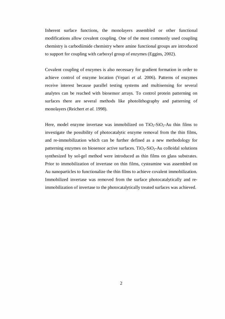
Biosensors can be classified with respect to either their bioreceptor or to their
transducer types (Figure 2.1). Most common bioreceptors are based on
antibody/antigen interactions, nucleic acid interactions, enzymatic interactions and
cellular interactions. Transducers can be classified basically as optical
measurements, mass-sensitive measurements and electrochemical measurements
(potentiometric and amperometric) (Cullum et al. 2000).
4
Figure 2.1 Schematics of biosensor classification
2.1.1 Enzyme Biosensors: General Concepts
In the large and expanding area of biosensor technology, great portion of the field
is devoted to enzyme biosensors due to their practical applications in clinical
diagnostics, analysis of metabolites, process and pollution monitoring. Enzymes
have many properties that are advantageous in biosensor applications like
- High specifity for analyte
- Being reusable
- Well-characterized mechanism of action
- Adaptation for conditions with stable forms of enzymes from thermophilic or
genetically modified organisms
An enzyme electrode is obtained by immobilizing a thin layer of enzyme. The
substrate or substrates which are going to be monitored diffuse into the enzyme
layer where the catalytic reaction occurs generating a product and consuming a
reactant, which can be detected electrochemically. Depending on the
electrochemical property, species are monitored potentiometrically,
Biosensor
Bioreceptor
Antibody
Enzyme
DNA
Cell
Transducer
Electrochemical
Optical
Mass-based
5
conductometrically or amperometrically (Shah et al. 2003) and signal can be
correlated back to the concentration.
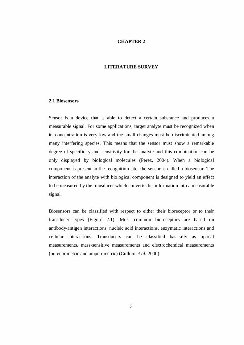
Amperometric biosensors have the advantage of being highly sensitive, rapid, and
inexpensive. They monitor a current flow between the working and the reference
electrode at a fixed potential. Either reactant or the product must be oxidable or
reducible at the electrode surface. In some cases, redox mediators are introduced to
allow fast electron transfer reactions (Taylor 1993).
Figure 2.2 A representation of a mediated amperometric biosensor
2.1.2 Application of Nanoparticles in Biosensors
Nanoparticles show unique chemical, physical and electronic properties that are
different from those of bulk materials. Many of them of different sizes and
compositions are now attainable and can be used to construct improved biosensing
devices. Although these nanoparticles play different roles in different sensing
systems based on their unique properties, the basic functions can be mainly
classified as immobilization of biomolecules, catalysis of electro-chemical
reactions, enhancement of electron transfer, labeling biomolecules and acting as
reactant. Main functions and advantages of nanoparticles in biosensing area are
summarized in Table 2.1.
6
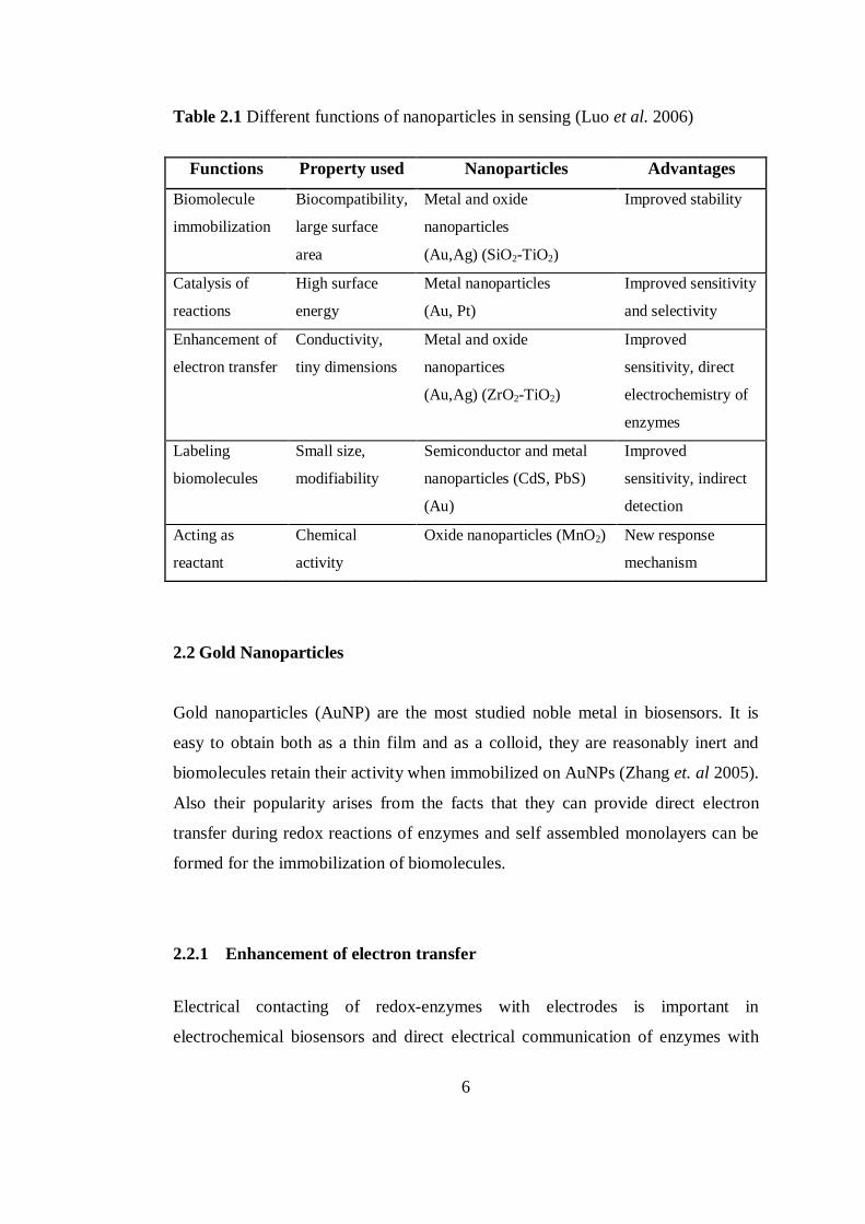
Table 2.1 Different functions of nanoparticles in sensing (Luo et al. 2006)
Functions Property used Nanoparticles Advantages
Biomolecule
immobilization
Biocompatibility,
large surface
area
Metal and oxide
nanoparticles
(Au,Ag) (SiO2-TiO2)
Improved stability
Catalysis of
reactions
High surface
energy
Metal nanoparticles
(Au, Pt)
Improved sensitivity
and selectivity
Enhancement of
electron transfer
Conductivity,
tiny dimensions
Metal and oxide
nanopartices
(Au,Ag) (ZrO2-TiO2)
Improved
sensitivity, direct
electrochemistry of
enzymes
Labeling
biomolecules
Small size,
modifiability
Semiconductor and metal
nanoparticles (CdS, PbS)
(Au)
Improved
sensitivity, indirect
detection
Acting as
reactant
Chemical
activity
Oxide nanoparticles (MnO2) New response
mechanism
2.2 Gold Nanoparticles
Gold nanoparticles (AuNP) are the most studied noble metal in biosensors. It is
easy to obtain both as a thin film and as a colloid, they are reasonably inert and
biomolecules retain their activity when immobilized on AuNPs (Zhang et. al 2005).
Also their popularity arises from the facts that they can provide direct electron
transfer during redox reactions of enzymes and self assembled monolayers can be
formed for the immobilization of biomolecules.
2.2.1 Enhancement of electron transfer
Electrical contacting of redox-enzymes with electrodes is important in
electrochemical biosensors and direct electrical communication of enzymes with
7
the electrode is generally a problem due to the thick insulating protein shells
blocking the electron transfer (Luo et al. 2006). Mostly, nanoscale metal particles
enhance this electron transfer. AuNPs can act as tiny conduction centers and are
site of electron transfer on the substrate surface allowing direct electron transfer
between redox proteins and electrode surfaces without the need of mediators
(Kumar, 2007).
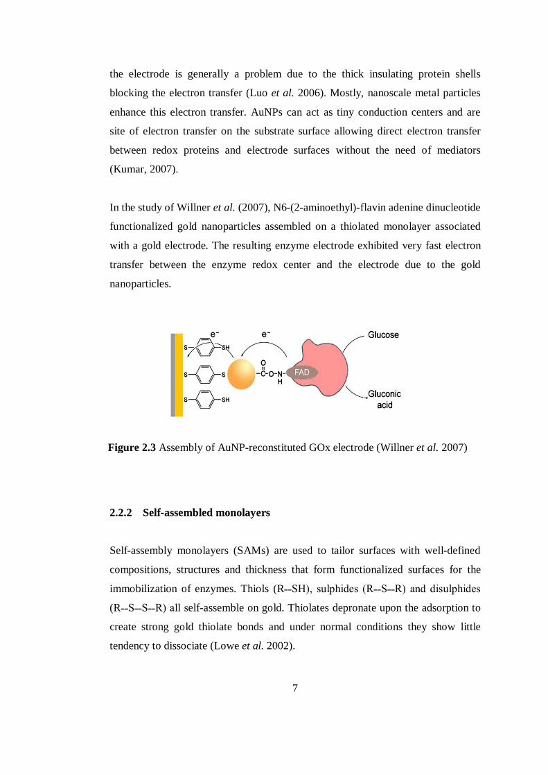
In the study of Willner et al. (2007), N6-(2-aminoethyl)-flavin adenine dinucleotide
functionalized gold nanoparticles assembled on a thiolated monolayer associated
with a gold electrode. The resulting enzyme electrode exhibited very fast electron
transfer between the enzyme redox center and the electrode due to the gold
nanoparticles.
2.2.2 Self-assembled monolayers
Self-assembly monolayers (SAMs) are used to tailor surfaces with well-defined
compositions, structures and thickness that form functionalized surfaces for the
immobilization of enzymes. Thiols (R˗˗SH), sulphides (R˗˗S˗˗R) and disulphides
(R˗˗S˗˗S˗˗R) all self-assemble on gold. Thiolates depronate upon the adsorption to
create strong gold thiolate bonds and under normal conditions they show little
tendency to dissociate (Lowe et al. 2002).
Au
Figure 2.3 Assembly of AuNP-reconstituted GOx electrode (Willner et al. 2007)
8
R˗˗SH + Au R˗˗S˗˗Au + e-+ H+ (2.1)
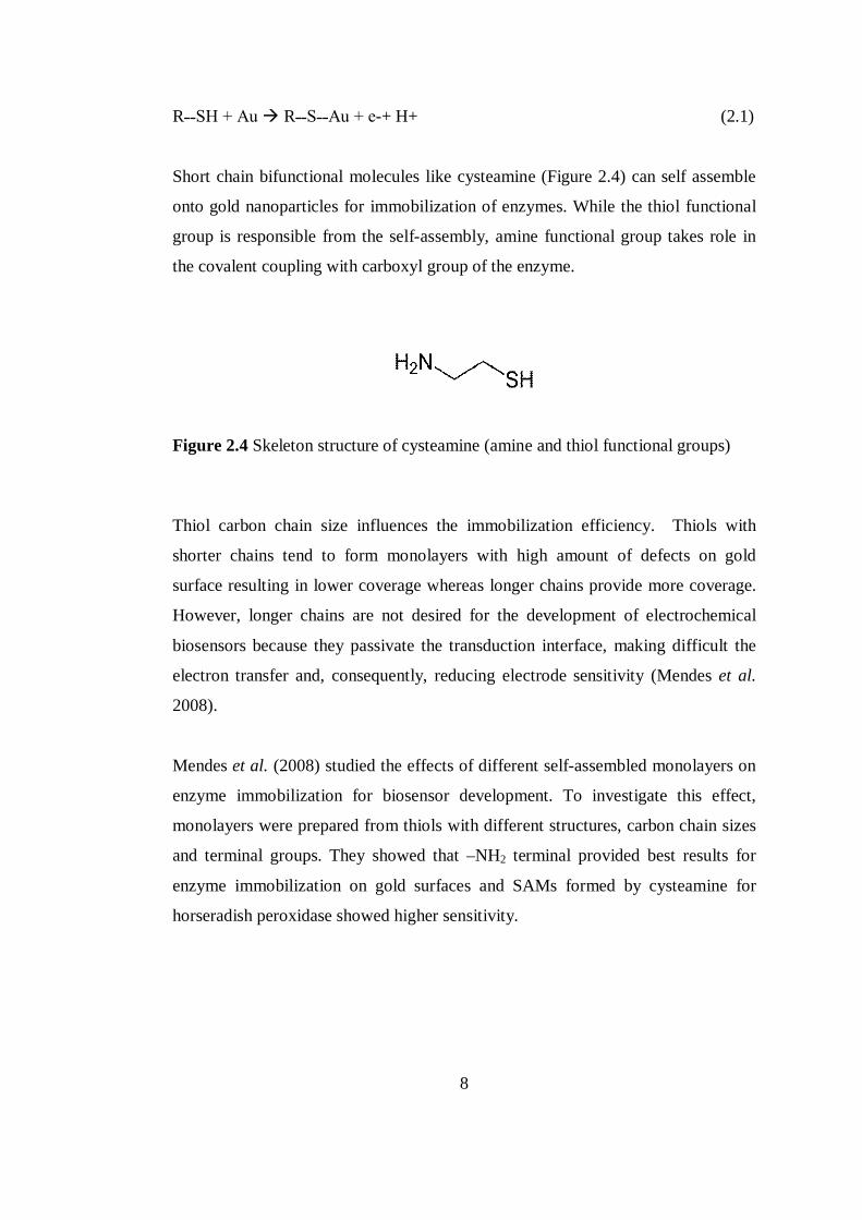
Short chain bifunctional molecules like cysteamine (Figure 2.4) can self assemble
onto gold nanoparticles for immobilization of enzymes. While the thiol functional
group is responsible from the self-assembly, amine functional group takes role in
the covalent coupling with carboxyl group of the enzyme.
Figure 2.4 Skeleton structure of cysteamine (amine and thiol functional groups)
Thiol carbon chain size influences the immobilization efficiency. Thiols with
shorter chains tend to form monolayers with high amount of defects on gold
surface resulting in lower coverage whereas longer chains provide more coverage.
However, longer chains are not desired for the development of electrochemical
biosensors because they passivate the transduction interface, making difficult the
electron transfer and, consequently, reducing electrode sensitivity (Mendes et al.
2008).
Mendes et al. (2008) studied the effects of different self-assembled monolayers on
enzyme immobilization for biosensor development. To investigate this effect,
monolayers were prepared from thiols with different structures, carbon chain sizes
and terminal groups. They showed that –NH2 terminal provided best results for
enzyme immobilization on gold surfaces and SAMs formed by cysteamine for
horseradish peroxidase showed higher sensitivity.
9
2.3 Titanium dioxide
Titanium dioxide belongs to the family of transition metal oxides. In the early
years, TiO2 was widely used as a pigment in paints, cosmetics and sunscreens.
After the discovery of the phenomenon of photocatalytic splitting of water on TiO2
electrode under UV light, intense research on TiO2 led to many areas like
photovoltaics and photocatalysis (Carp et al. 2004). Also TiO2 is promising for
biosensor applications due to their non-toxicity, chemical and physical stability
being biocompatible matrixes for enzyme immobilization and provide enhancement
of electron transfer between the redox enzymes and the electrodes.
TiO2 can be prepared in the form of powder, crystals, or thin films. Both powders
and films can be built up from crystallites ranging from a few nanometers to
several micrometers. The most suitable method of thin film synthesis is sol-gel
methods. It is also widely used for multicomponent structures due to ability of
good mixing. Other oxides like silica and various metal ions like Au+3 can be
introduced to the TiO2 films with this method (Carp et. al 2004).
Two paths can be followed for the production of TiO2 with sol-gel method, non-
alkoxide and alkoxide. Inorganic salts are used in non-alkoxide route while metal
alkoxides are used as precursors in alkoxide route. Commonly used titanium
precursors are titanium(IV) n-butoxide, titanium(IV) ethoxide and titanium(IV) iso-
propoxide. In latter route TiO2 sol or gel is formed by hydrolysis and condensation
of titanium alkoxides. These reactions are followed by a thermal treatment to
remove the organic part and to crystallize TiO2 into desired phase. Titanium
dioxide has three crystalline phases; rutile is the most stable phase, anatase is the
most photocatalytically active phase and brookite phase does not have any
photocatalytic activity (Mills et al. 1997). Crystalline phase conversion determines
the use of TiO2 as photocatalyst, catalyst or ceramic material.
Although being an excellent photocatalyst, use of bulk TiO2 may have some
drawbacks. It sinters easily and it is difficult to obtain high surface area, thus
10
decrease in photocatalytic activity is observed (Schrijnemakers et al. 1999). So
studies to increase the catalytic efficiency of TiO2 by modifications with noble
metals, transition metals and with other metal oxides attracted great attention. The
formation of mixed TiO2-SiO2 films improves photocatalytic efficiency through the
generation of new active sites and improved thermal stability and surface area of
titania (Carp et al. 2004). It is shown in many studies that TiO2-SiO2 materials have
higher photocatalytic activity than pure TiO2.
2.3.1 Photocatalysis
Photocatalysis is defined as the accelaration of a photoreaction by the presence of a
catalyst (Mills et. al 1997). A photocatalyst is characterized by its capability to
adsorb simultaneously two reactants, which can be reduced and oxidized by a
photonic activation through an efficient absorption (Carp et al. 2004).
Photocatalytic reaction is a series of chain reactions which takes place over the
surface of the catalyst initiated by the absorption of photons with appropriate
wavelength and generation of electron/hole pair.
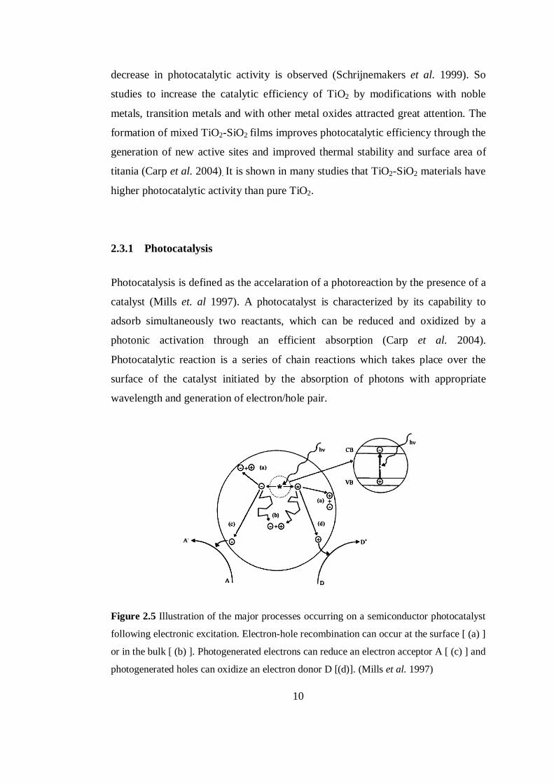
Figure 2.5 Illustration of the major processes occurring on a semiconductor photocatalyst
following electronic excitation. Electron-hole recombination can occur at the surface [ (a) ]
or in the bulk [ (b) ]. Photogenerated electrons can reduce an electron acceptor A [ (c) ] and
photogenerated holes can oxidize an electron donor D [(d)]. (Mills et al. 1997)
11
Ideally, a semiconductor photocatalyst should be chemically and biologically inert,
photocatalytically stable, easy to produce and to use, efficiently activated by
sunlight, able to efficiently catalyze reactions, cheap, and without risks for the
environment or humans (Carp et al. 2004). Since as a semiconductor TiO2 has most
of those advantages, it is widely used.
Activation of the semiconductor for photocatalytic reactions is achieved with the
adsorption of photon having higher energy than the band gap energy. Band gap
energies of rutile and anatase phases of TiO2 can be seen below.
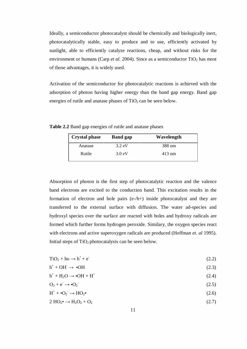
Table 2.2 Band gap energies of rutile and anatase phases
Crystal phase Band gap Wavelength
Anatase
Rutile
3.2 eV
3.0 eV
388 nm
413 nm
Absorption of photon is the first step of photocatalytic reaction and the valence
band electrons are excited to the conduction band. This excitation results in the
formation of electron and hole pairs (e-/h+) inside photocatalyst and they are
transferred to the external surface with diffusion. The water ad-species and
hydroxyl species over the surface are reacted with holes and hydroxy radicals are
formed which further forms hydrogen peroxide. Similary, the oxygen species react
with electrons and active superoxygen radicals are produced (Hoffman et. al 1995).
Initial steps of TiO2 photocatalysis can be seen below.
TiO2 + hυ → h+ + e- (2.2)
h+ + OH- → •OH (2.3)
h+ + H2O → •OH + H+ (2.4)
O2 + e- → •O2- (2.5)
H+ + •O2- → HO2• (2.6)
2 HO2• → H2O2 + O2 (2.7)
12
Those photocatalytic reactions are not specific and therefore the radicals formed at
the end of those reactions have potential to oxidize many organic compounds.
2.4 Thin Films Synthesis
For the performance of any biosensor, reversibility, reproducibility and speed of
response are very important issues. In any sensor analyte molecules have to diffuse
into the sensing component and the products formed must diffuse out. Therefore
reversibility and speed of the sensor response can be well improved by having
thinner sensing layers (Davis et al. 2005) and much effort has been performed for
the assembly of thins films to biosensor technology. Self-assembled monolayers,
plasma assisted techniques and chemical solution deposition are some of the
methods to obtain thin films.
Self-assembled monolayers are formed by strong chemical bond between the
building species and the surface of the substrate. It is possible to form ultrathin,
stable and ordered monolayers of desired functional groups for immobilizing
biomolecules onto the surface (Davis et al. 2005).
Treatment of solid surfaces by different types of plasma such as microwave, radio
frequency, corona discharge is often used for modification and plasma surface
modifications exhibit complex, multifunctional chemistries; crosslinked and
branched structures (Ratner, 1996). Plasma polymerization is a thin film-forming
process, where thin and adherent layers are deposited directly on surfaces of the
substrates without any fabrication (Sever et al. 2009). The resulting films are
homogeneous and extremely thin and the sensors produced by using this method
exhibits high reproducibility and low noise (Mutlu et al. 2008).
Sol-gel type chemical solution deposition technique is a highly flexible method for
the fabrication of thin films (Schwartz et al. 2004). Since this technique was
employed in this study, detailed information will be given.
13
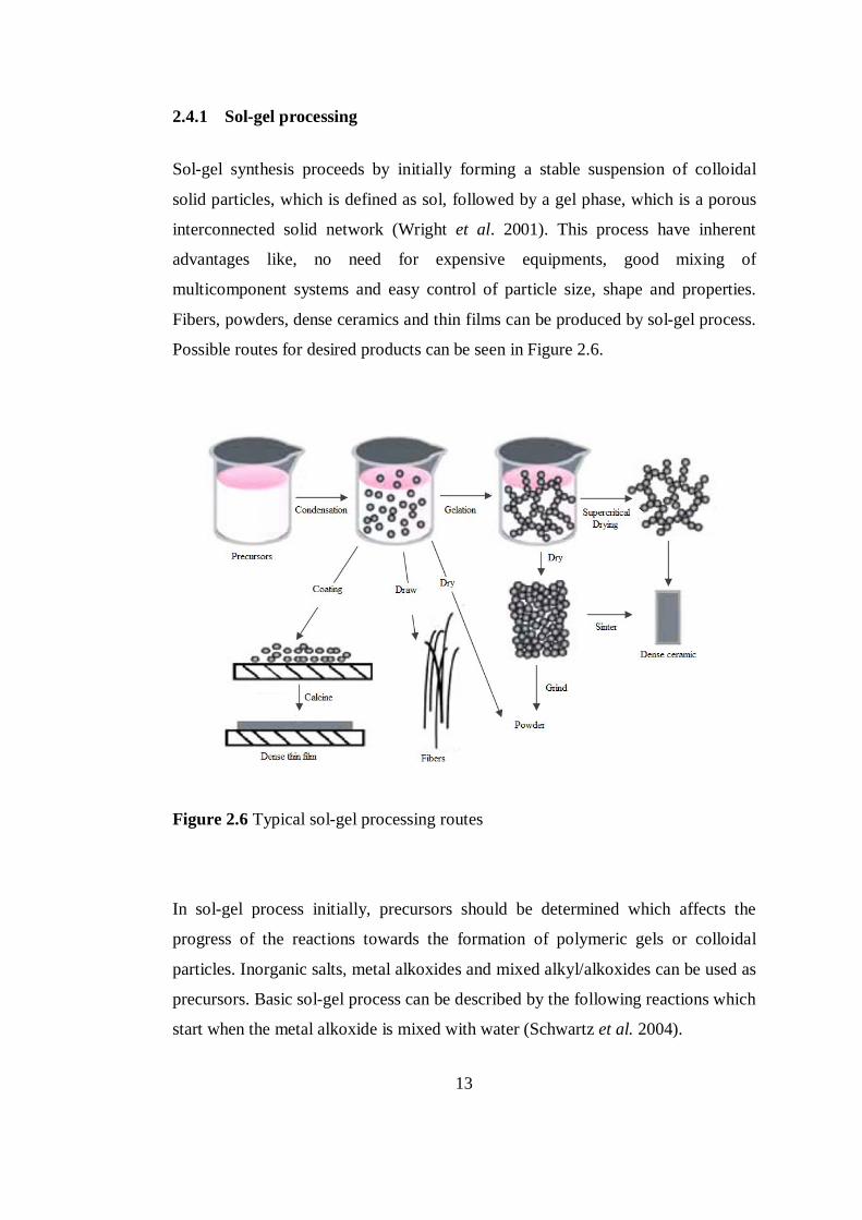
2.4.1 Sol-gel processing
Sol-gel synthesis proceeds by initially forming a stable suspension of colloidal
solid particles, which is defined as sol, followed by a gel phase, which is a porous
interconnected solid network (Wright et al. 2001). This process have inherent
advantages like, no need for expensive equipments, good mixing of
multicomponent systems and easy control of particle size, shape and properties.
Fibers, powders, dense ceramics and thin films can be produced by sol-gel process.
Possible routes for desired products can be seen in Figure 2.6.
Figure 2.6 Typical sol-gel processing routes
In sol-gel process initially, precursors should be determined which affects the
progress of the reactions towards the formation of polymeric gels or colloidal
particles. Inorganic salts, metal alkoxides and mixed alkyl/alkoxides can be used as
precursors. Basic sol-gel process can be described by the following reactions which
start when the metal alkoxide is mixed with water (Schwartz et al. 2004).
14
Hydrolysis
M(OR)x + H2O M(OR)x-1(OH) + ROH (2.8)
Condensation (alcohol elimination)
2 M(OR)x-1(OH) M2O(OR)2x-3(OH) + ROH (2.9)
Condensation (water elimination)
2 M(OR)x-1(OH) M2O(OR)2x-2(OH) + H2O (2.10)
Hydrolysis is favored when the water to alkoxide ratio is increased. In general,
under stoichiometric addition of water, the alcohol producing condensation process
is dominant, whereas for excess amount of water, water forming condensation
reaction is favored (Brinker et al. 1990).
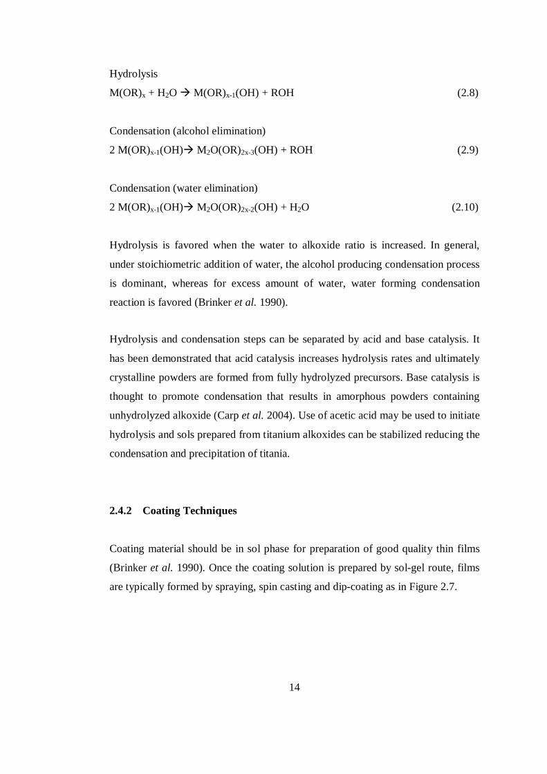
Hydrolysis and condensation steps can be separated by acid and base catalysis. It
has been demonstrated that acid catalysis increases hydrolysis rates and ultimately
crystalline powders are formed from fully hydrolyzed precursors. Base catalysis is
thought to promote condensation that results in amorphous powders containing
unhydrolyzed alkoxide (Carp et al. 2004). Use of acetic acid may be used to initiate
hydrolysis and sols prepared from titanium alkoxides can be stabilized reducing the
condensation and precipitation of titania.
2.4.2 Coating Techniques
Coating material should be in sol phase for preparation of good quality thin films
(Brinker et al. 1990). Once the coating solution is prepared by sol-gel route, films
are typically formed by spraying, spin casting and dip-coating as in Figure 2.7.
15
In spin-coating, film of coating solution is spreaded on a substrate which is
spinned. It is divided into four stages; deposition, spin-up, spin-off and evaporation
(Bornside et al. 1987). The angular velocity, spin time and viscosity of the solution
affect the thickness of the wet film. This technique applies well to disks and
cylindrical surfaces.
Spray-coating technique potentially has the advantage of film deposition on non-
planar structures and is based on transforming the coating solution to an aerosol
with an ultrasonic nebulizer or pressure driven nozzle based systems (Schwartz et
al. 2004). Coverage can be improved by reducing the droplet size however it is
difficult to maintain uniform film thicknesses.
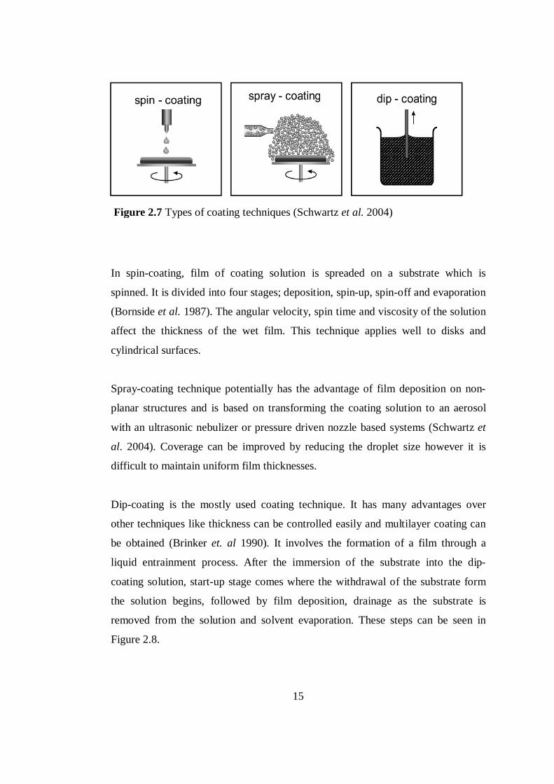
Dip-coating is the mostly used coating technique. It has many advantages over
other techniques like thickness can be controlled easily and multilayer coating can
be obtained (Brinker et. al 1990). It involves the formation of a film through a
liquid entrainment process. After the immersion of the substrate into the dip-
coating solution, start-up stage comes where the withdrawal of the substrate form
the solution begins, followed by film deposition, drainage as the substrate is
removed from the solution and solvent evaporation. These steps can be seen in
Figure 2.8.
Figure 2.7 Types of coating techniques (Schwartz et al. 2004)
16
Figure 2.8 Steps of dipcoating; immersion, start-up, deposition, drainage and
evaporation, respectively (Brinker et al. 1990)
Viscous drag, gravitational forces, surface tension of the curved meniscus affects
the thickness of the film that is formed (Brinker et al. 1990). Also, sticking
probability of the precursor and aggregation plays role in the thickness.
After coating, thermal treatment is the last stage to obtain thin films. Typically,
sol−gel-derived precipitates are amorphous in nature, requiring further heat
treatment to induce crystallization. To remove the remaining solvent entrapped,
thin films are dried and further to obtain the desired oxide phase and the remove
the organic moieties, thin films are calcined at appropriate temperatures.
2.5 Enzymes
Enzymes are types of proteins which catalyze biochemical reactions. They increase
the rate of reaction by lowering the activation energy without undergoing any
permanent change (Horton et al. 1996), however enzymes differ from most other
catalysts by being much more specific.
Like all other proteins, enzymes are composed of amino acids and the basic
properties of them are determined by their protein nature. Amino acids are consist
of an amino (NH2) and a carboxylic acid (COOH) group attached to a central
carbon atom and the variation of them is determined by the ‘R’ group, which is
also called as side chain (Figure 2.9).
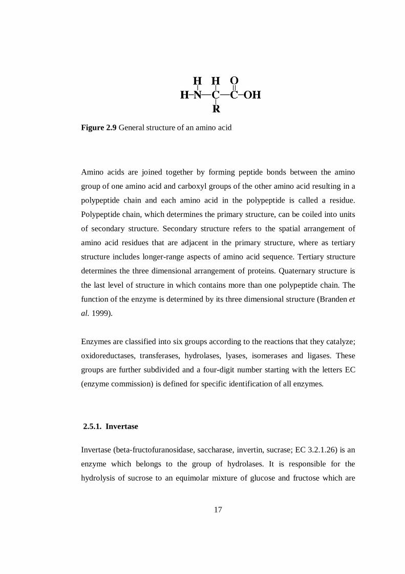
17
Figure 2.9 General structure of an amino acid
Amino acids are joined together by forming peptide bonds between the amino
group of one amino acid and carboxyl groups of the other amino acid resulting in a
polypeptide chain and each amino acid in the polypeptide is called a residue.
Polypeptide chain, which determines the primary structure, can be coiled into units
of secondary structure. Secondary structure refers to the spatial arrangement of
amino acid residues that are adjacent in the primary structure, where as tertiary
structure includes longer-range aspects of amino acid sequence. Tertiary structure
determines the three dimensional arrangement of proteins. Quaternary structure is
the last level of structure in which contains more than one polypeptide chain. The
function of the enzyme is determined by its three dimensional structure (Branden et
al. 1999).
Enzymes are classified into six groups according to the reactions that they catalyze;
oxidoreductases, transferases, hydrolases, lyases, isomerases and ligases. These
groups are further subdivided and a four-digit number starting with the letters EC
(enzyme commission) is defined for specific identification of all enzymes.
2.5.1. Invertase
Invertase (beta-fructofuranosidase, saccharase, invertin, sucrase; EC 3.2.1.26) is an
enzyme which belongs to the group of hydrolases. It is responsible for the
hydrolysis of sucrose to an equimolar mixture of glucose and fructose which are
18
known as reducing sugars. The reaction catalyzed by the invertase is shown in
Figure 2.10.
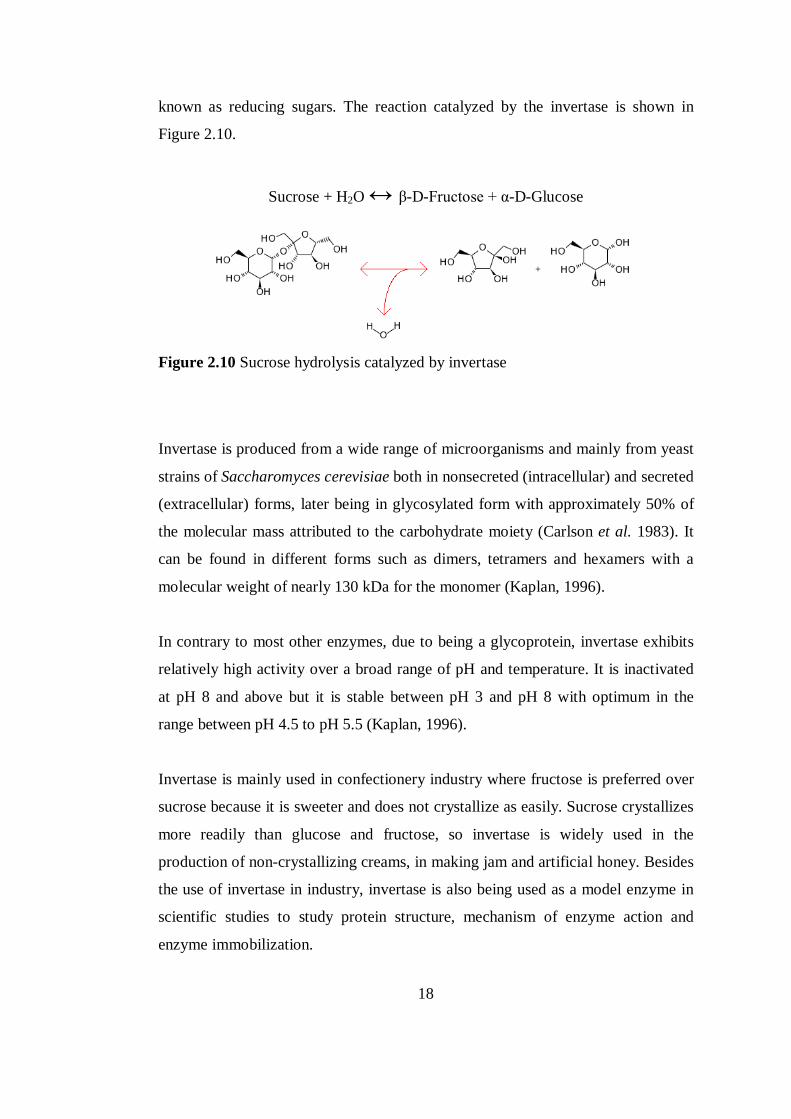
Sucrose + H2O ↔ β-D-Fructose + α-D-Glucose
Figure 2.10 Sucrose hydrolysis catalyzed by invertase
Invertase is produced from a wide range of microorganisms and mainly from yeast
strains of Saccharomyces cerevisiae both in nonsecreted (intracellular) and secreted
(extracellular) forms, later being in glycosylated form with approximately 50% of
the molecular mass attributed to the carbohydrate moiety (Carlson et al. 1983). It
can be found in different forms such as dimers, tetramers and hexamers with a
molecular weight of nearly 130 kDa for the monomer (Kaplan, 1996).
In contrary to most other enzymes, due to being a glycoprotein, invertase exhibits
relatively high activity over a broad range of pH and temperature. It is inactivated
at pH 8 and above but it is stable between pH 3 and pH 8 with optimum in the
range between pH 4.5 to pH 5.5 (Kaplan, 1996).
Invertase is mainly used in confectionery industry where fructose is preferred over
sucrose because it is sweeter and does not crystallize as easily. Sucrose crystallizes
more readily than glucose and fructose, so invertase is widely used in the
production of non-crystallizing creams, in making jam and artificial honey. Besides
the use of invertase in industry, invertase is also being used as a model enzyme in
scientific studies to study protein structure, mechanism of enzyme action and
enzyme immobilization.
19
2.6 Immobilization of enzymes
Immobilization of an enzyme is achieved by restricting its mobility via chemical or
physical methods. It is mostly used for the enhancement of enzyme properties for
the applications in areas like controlled release systems, determination of
environmental pollutants and biosensor design. Although the activity of enzyme
may decrease during the immobilization process, it has many advantages like
simplified separation, easy recovery of immobilized enzymes from the reaction
medium and they can be repeatedly used reducing the cost of operation. Also
enzymes can be stabilized by immobilization. Support materials can alter
parameters like optimal pH and temperature which may be advantageous (Sleytr et
al. 1993). Although different classifications can be made, there are five main
immobilization techniques. The choice of method depends on parameters like the
nature of the enzyme, required stability, reusability and cost.
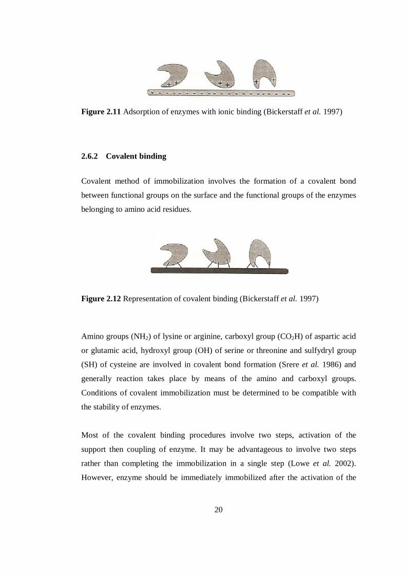
2.6.1 Adsorption
Adsorption, which it is the simplest way of immobilization, involves reversible
interactions between the enzyme and the support material. Reversible surface
interactions are mostly due to van der Waals forces, ionic bonding, hydrogen
bonding and hydrophobic interactions (Bickerstaff et al. 1997). Besides being a
cheap and quick immobilization technique, active site of the enzyme stays intact
and may demonstrate higher activity. However, the most significant disadvantage
is the leakage of enzymes from the support. Non-specific binding can be a problem
for the cases of the interaction of substrate, product or residual contaminant with
the support.
20
Figure 2.11 Adsorption of enzymes with ionic binding (Bickerstaff et al. 1997)
2.6.2 Covalent binding
Covalent method of immobilization involves the formation of a covalent bond
between functional groups on the surface and the functional groups of the enzymes
belonging to amino acid residues.
Figure 2.12 Representation of covalent binding (Bickerstaff et al. 1997)
Amino groups (NH2) of lysine or arginine, carboxyl group (CO2H) of aspartic acid
or glutamic acid, hydroxyl group (OH) of serine or threonine and sulfydryl group
(SH) of cysteine are involved in covalent bond formation (Srere et al. 1986) and
generally reaction takes place by means of the amino and carboxyl groups.
Conditions of covalent immobilization must be determined to be compatible with
the stability of enzymes.
Most of the covalent binding procedures involve two steps, activation of the
support then coupling of enzyme. It may be advantageous to involve two steps
rather than completing the immobilization in a single step (Lowe et al. 2002).
However, enzyme should be immediately immobilized after the activation of the
21
support because activated supports have unstable and reactive functional groups
(Bickerstaff et al. 1997)
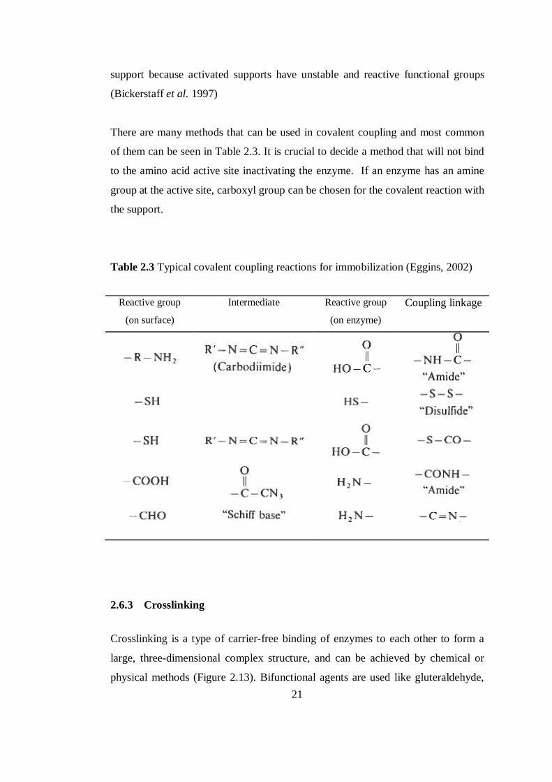
There are many methods that can be used in covalent coupling and most common
of them can be seen in Table 2.3. It is crucial to decide a method that will not bind
to the amino acid active site inactivating the enzyme. If an enzyme has an amine
group at the active site, carboxyl group can be chosen for the covalent reaction with
the support.
Table 2.3 Typical covalent coupling reactions for immobilization (Eggins, 2002)
Reactive group
(on surface)
Intermediate Reactive group
(on enzyme) Coupling linkage
2.6.3 Crosslinking
Crosslinking is a type of carrier-free binding of enzymes to each other to form a
large, three-dimensional complex structure, and can be achieved by chemical or
physical methods (Figure 2.13). Bifunctional agents are used like gluteraldehyde,
22
dinitrobenzene and diazobenzidin as crosslinkers. Main disadvantage of this
technique is crosslinking an enzyme to itself is both expensive and insufficient.
Enzymatic activity might reduce relatively.
Figure 2.13 Crosslinked enzymes (Bickerstaff et al. 1997)
2.6.4 Entrapment
The entrapment method depends on the localization of enzyme in the lattice of a
polymer (Figure 2.14). Via entrapment, enzyme movement is restricted by the
lattice structure but the enzyme molecules are still free in solution. Widely used
lattices are polyacrylamide hydrogels, polyurethane and starch gels, naylon and
conducting polymers (Eggins, 2002). The porosity of the gel must be controlled to
prevent leakage but allow movement of substrate and product. Entrapment can be
enhanced by crosslinking with the lattice and the enzyme. Unavoidably lattice can
act as a barrier to mass transfer.
Figure 2.14 Representation of entrapment technique (Bickerstaff et al. 1997)
23
2.6.5 Encapsulation
Encapsulation of enzymes is similar to entrapment but it is achieved by enveloping
the biological components within various forms of semipermeable membranes.
Many materials have been used to construct microcapsules nylon and cellulose
being the most popular ones.
Figure 2.15 Encapsulation type of immobilization (Bickerstaff et al. 1997)
2.7 Enzyme Patterning
The area of protein patterning was arised as a critical technology to organize
multiple biomolecules on surfaces with resolutions from the micron to the
nanometer scale for biological-electronic devices. Array or pattern development
begun to receive attention for its broad range of applications from fundamental cell
biology to thin-film biosensing like lab-on-a-chip biosensors (Li et al. 2008).
Current methods capable of providing accurate position and dimension control on
patterned proteins include photoresist lithography, photochemistry and self-
assembled monolayers.
2.7.1 Conventional photoresist technology
For protein patterning with conventional photoresist technology, chemical linkers
with different pendant groups are used. Silane coupling agents are generally
preferred to attach enzymes to silica or metal surfaces because they can withstand
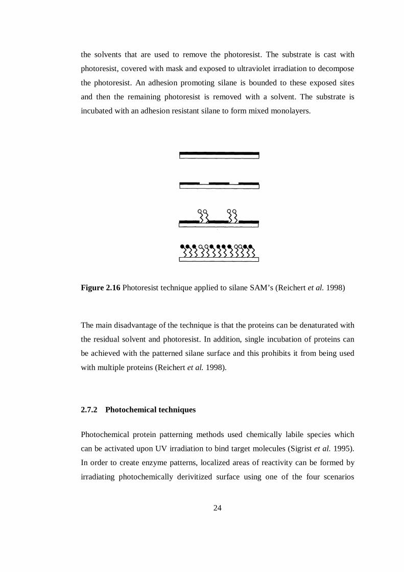
24
the solvents that are used to remove the photoresist. The substrate is cast with
photoresist, covered with mask and exposed to ultraviolet irradiation to decompose
the photoresist. An adhesion promoting silane is bounded to these exposed sites
and then the remaining photoresist is removed with a solvent. The substrate is
incubated with an adhesion resistant silane to form mixed monolayers.
Figure 2.16 Photoresist technique applied to silane SAM’s (Reichert et al. 1998)
The main disadvantage of the technique is that the proteins can be denaturated with
the residual solvent and photoresist. In addition, single incubation of proteins can
be achieved with the patterned silane surface and this prohibits it from being used
with multiple proteins (Reichert et al. 1998).
2.7.2 Photochemical techniques
Photochemical protein patterning methods used chemically labile species which
can be activated upon UV irradiation to bind target molecules (Sigrist et al. 1995).
In order to create enzyme patterns, localized areas of reactivity can be formed by
irradiating photochemically derivitized surface using one of the four scenarios
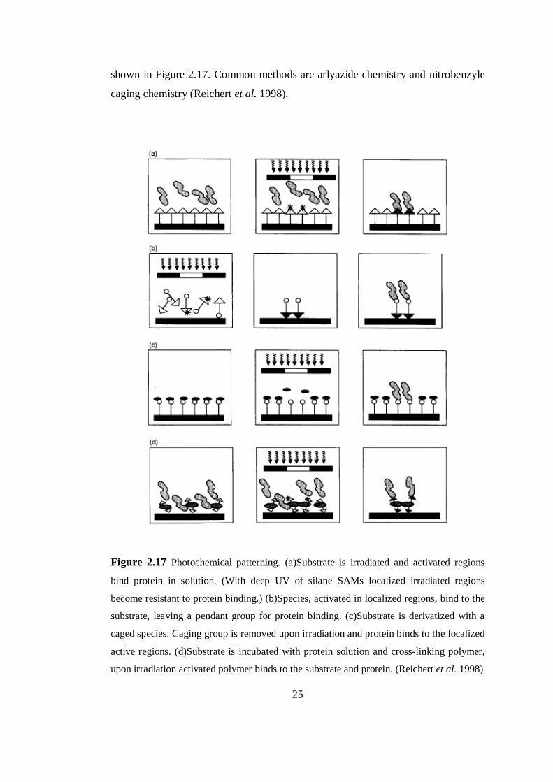
25
shown in Figure 2.17. Common methods are arlyazide chemistry and nitrobenzyle
caging chemistry (Reichert et al. 1998).
Figure 2.17 Photochemical patterning. (a)Substrate is irradiated and activated regions
bind protein in solution. (With deep UV of silane SAMs localized irradiated regions
become resistant to protein binding.) (b)Species, activated in localized regions, bind to the
substrate, leaving a pendant group for protein binding. (c)Substrate is derivatized with a
caged species. Caging group is removed upon irradiation and protein binds to the localized
active regions. (d)Substrate is incubated with protein solution and cross-linking polymer,
upon irradiation activated polymer binds to the substrate and protein. (Reichert et al. 1998)
26
Arylazide photochemistry is used to selectively immobilize proteins via an azide
aromatic group (Pritchard et al. 1995). Substrate was incubated with a protein
solution and when irradiated with a mask, free azide group was transformed to the
active nitrene and bonded to a protein in the incubation solution. The common
disadvantage with this chemistry is that the protein must be in contact with the
derivitizes surface during the irradiation process. UV range of 265-275 nm is most
likely to damage proteins (Pritchard et al. 1995) and during irradiation, protein
activity can be reduced. However, some substitutions on arlyazide ring enables the
compound to be activated at higher wavelenghts.
Nitrobenzyl caging chemisrty involves intorducing a chemical group to a molecule
which prevents its activity. Caging group is converted into ketone and
carbondioxide with the irradiation of UV light and the released molecule retains its
activity. By attaching the caged moiety to molecules which can bind to aminoacids,
enzymes can be patterned with photolithography with selectively removing the
cage.
2.7.3 Self Assembled Monolayers
As described alkane thiols or alkyl silanes assemble into organized layers when
they are exposed to metal surface. One end group remains free while the other end
group of the molecular chain binds to the surface. In order to change the binding or
surface energy of the monolayer, reactive end groups can be varied. By creating
mixed self-assembled monolayers on a surface, proteins can be patterned within the
regions of the hydrophilic or adhesion promoting layers (Reichert et al. 1998).
Bhatia (1989) examined ultraviolet irradiation of SAMs and the pendant thiol
groups are converted to sulfonate groups which inhibit protein adsorption upon
deep UV irradiation. Silica surfaces modified with 3-mercaptoproplymethoxy
silane were masked and irradiated with 193 nm UV light. The patterned surfaces
27
were incubated with glucose oxidase enzyme patterns within the thiol regions were
observed.
It is also possible to produce mixed SAMs of alkane thiols on gold surfaces with
microwriting, micromachining, stamping and UV microlithography. Delamarche et
al. (1996) examined photochemistry with alkane thiol SAMs on gold surfaces to
create protein patterns. The terminal active ester group of alkane thiols on gold
were converted to photoactivatable group benzopheone. Surface was incubated
with the protein solution and irradiated with UV light. Biradical formation at the
ketyl center of the photolabile group was occured with irradiation and proceeded by
a C-C bond with the protein on radical recombination.
This method suffers from the same issues as photoresist technique as it is difficult
to have multiple enzyme patterns on a surface. Although the conventional
photolithography and SAMs can also be used, photochemical methods are leading
for the application for enzyme assays to pattern multiple proteins on a single
surface.
28
CHAPTER 3
3 MATERIALS AND METHODS
3.1 Materials
Microscope slides which were used as glass substrates were obtained from
Industrial Quality. Chemicals used for synthesis of colloidal solution, titanium (IV)
i-propoxide (TTIP), LUDOX SM-30 (information can be seen in Appendix A),
polyethylene glycol 4000 (PEG 4000) and AuCl3, were purchased from SIGMA-
ALDRICH.
Invertase (EC 3.2.1.26) was purchased from NOVO NORDISK. Cysteamine was
obtained from FLUKA. D-(+)- glucose were purchased from MERCK. All other
reagents were of analytical grade and obtained either from SIGMA or MERCK.
Ultrapure water was used during the experiments.
3.2 Preparation of thin film coatings
3.2.1 Pretreatment of glass substrates
Microscope slides, 25mm x 75 mm x 1 mm, were used as glass substrates. KOH
solution was utilized for cleaning and etching purposes. Glass substrates were
immersed in 1M KOH solution for 48 hours and rinsed with distilled water until
pH 7. After rinsing, substrates were ultrasonicated in ethanol for 1 hour and finally
they were wiped dried at 100oC for 1 hour. After pretreatment, glass substrates
were stored in a dessicator.
29
3.2.2 Synthesis of colloidal solution
TiO2-SiO2 binary mixtures was prepared using TTIP as TiO2 precursor and
colloidal silica. 5 ml of TTIP, was added dropwise to 1 ml acetic acid and 200 ml
distilled water mixture and acetic acid catalysized hydrolysis started. Then 0.7 ml
of 65% (v/v) HNO3 was added to adjust the pH to 3.5. The solution was stirred for
30 minutes at 80oC in a water bath with a reflux condenser and 2 hours at room
temperature. Then 6.4 ml Ludox-SM 30, colloidal silica, was added to introduce
silica nanoparticles to the solution and stirred overnight (22.5 hours). 12.5 gr PEG
4000 was dissolved in 25 ml distilled water and 21.3 ml of that PEG 4000 solution
was added and stirred for another 24 hours.
Au was introduced to the final TiO2-SiO2 solution in the form of HAuCl4. HAuCl4
was derived form AuCl3 by dissolving 0.1 g of it in 32.973 ml distilled water and
adding 27 µl HCl. 18.5 ml of HAuCl4 solution was added to the TiO2-SiO2
solution and left stirring for 24 hours. Rest of the HAuCl4 solution was stored at
4oC for further use.
3.2.3 Dip-coating of glass substrates
Pretreated glass substrates were modified with the prepared solution by dip-coating
technique as shown in Figure 3.2. 25mm x 60 mm x 1 mm region of the pretreated
substrates were immersed in TiO2SiO2-Au colloidal solution and withdrawn with a
speed of 5 cm/min. In order to have a continuous film, coating is done with 3
successive layers and between each successive layers, substrates are dried at 100oC
for 15 minutes to provide adhesion before the subsequent layer.
30
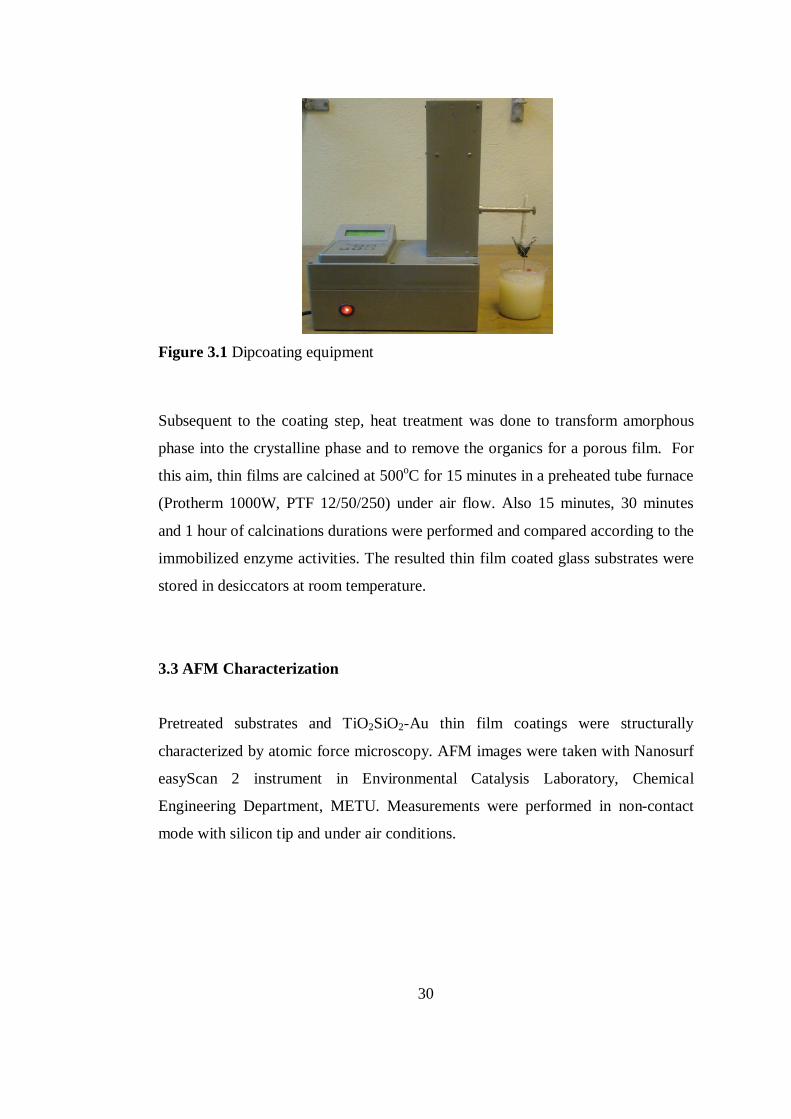
Figure 3.1 Dipcoating equipment
Subsequent to the coating step, heat treatment was done to transform amorphous
phase into the crystalline phase and to remove the organics for a porous film. For
this aim, thin films are calcined at 500oC for 15 minutes in a preheated tube furnace
(Protherm 1000W, PTF 12/50/250) under air flow. Also 15 minutes, 30 minutes
and 1 hour of calcinations durations were performed and compared according to the
immobilized enzyme activities. The resulted thin film coated glass substrates were
stored in desiccators at room temperature.
3.3 AFM Characterization
Pretreated substrates and TiO2SiO2-Au thin film coatings were structurally
characterized by atomic force microscopy. AFM images were taken with Nanosurf
easyScan 2 instrument in Environmental Catalysis Laboratory, Chemical
Engineering Department, METU. Measurements were performed in non-contact
mode with silicon tip and under air conditions.
31
3.4 SEM Analysis
Thin films and invertase immobilized thin films were examined by scanning
electron microscopy (QUANTA 400F Field Emission) in Central Laboratory,
METU with accelerating voltage of 30 kV and at 2000 and 250 000 magnifications.
No metal coating was applied to the samples for SEM analysis.
3.5 Immobilization studies
3.5.1 Linker deposition
As a linker, cysteamine was deposited by immersing thin film coated glass
substrates in a 200 ml of 0.20 mM aqueous solution of cysteamine. The solution
was stirred with a magnetic stirrer at 250 rpm for 3.5 hours at room temperature
under dark conditions. Thin films were washed with distilled water to remove the
physically bound cysteamine from the surface. Fresh cysteamine solutions were
prepared for every deposition process.
3.5.2 Immobilization of invertase
10 µg/ml invertase immobilization solution was prepared in 0.1 M, pH 5.0 sodium-
acetate buffer. Cysteamine deposited thin film coated glass substrates were dipped
into the 200 ml immobilization solution and stirred with a magnetic stirrer at 250
rpm in order to enhance the mass transfer conditions at room temperature for 12
hours under dark conditions. Finally invertase immobilized films were washed with
100 ml of 0.1 M, pH 5.0 sodium acetate buffer to remove the weakly bound
enzymes from the films. Activity assays were immediately performed or invertase
immobilized thin films were stored in buffer at 4oC until the assay.
32
3.5.3 Invertase activity measurements
Activity measurements of immobilized invertase and free invertase were conducted
spectrophotometrically with double-beam UV-Visible Spectrophotometer (Thermo
Electron Corporation, Nicolet Evolution 100). 50 mg/ml sucrose in 0.1 M, pH 5.0
sodium acetate buffer was utilized as the substrate solution. Reducing sugar
concentration, which was produced with the hydrolysis of sucrose, was monitored
by DNSA method (Appendix B). For this purpose, 1 ml samples taken from the
reaction solution were added to the 1 ml of DNSA at determined intervals and well
mixed with vortexing. Samples were treated with 5 minutes of boiling water and
with 5 minutes of ice bath. After the samples were reached the room temperature,
the absorbance data were recorded at 540 nm.
Activity assays for each sample were repeated at least two times and all activity
assays were performed under dark conditions. One enzyme unit (EU) was defined
as the amount of enzyme which catalyzes the hydrolysis of 1 µmole sucrose per
minute under the reaction conditions (40oC, pH 5.0). Initial reaction rates were
calculated from the initial linear part of the reaction progress curve.
The glucose standard curve (Appendix C) was plotted to have the association of
absorbance with the concentration of reducing sugar for EU calculations. Standart
glucose solutions in the range of 50-150 µg/ml were prepared in 0.1 M, pH 5.0
sodium acetate buffer. 1 ml of glucose samples were mixed with 1 ml of DNSA
reagent, kept in boiling water for 5 minutes and ice bath in 5 minutes. After the
samples were reached the room temperature, the absorbance data were recorded at
540 nm.
3.5.3.1 Free invertase activity measurements
For free invertase activity, the reaction was started by the addition of 1 ml of
2µg/ml invertase solution to the 24 ml of preheated substrate solution in a 40oC
shaking water bath (Nüve ST 102). 1 ml of reaction solution samples were
33
collected with a time interval of 2 minutes for 10 minutes. Glucose samples were
prepared for the glucose standard curve and enzyme activities were calculated as
EU/ml. The calculation can be seen below. The equation was divided by 2 due to
the fact that two reducing sugars, glucose and fructose, are formed from the
hydrolysis of one sucrose.
EUml =
∆OD/∆t∆OD/∆c ×
1 mmol180 mg glucose ×
1000 µmol1 mmol ×
25 ml reaction mixture1 ml enzyme solution /2
(3.1)
ΔOD = change in absorbance at 540 nm
Δt = change in time, min
Δc = change in reducing sugar concentration
ΔOD/ Δt = slope of the reaction progress curve
∆OD/∆c = slope of the glucose standard curve
3.5.3.2 Immobilized invertase activity measurements
100 ml of substrate (sucrose) solution was poured into a tube with 4 cm diameter
and 16 cm lengh and preincubated in shaking water bath at 40oC until thermal
equilibrium was reached. Immobilized enzyme activity assay was started by
dipping invertase immobilized film into the sucrose solution. Samples were
collected with a time interval of 5 minutes for 40 minutes. Glucose standarts were
prepared as explained in invertase activity measurement part. Immobilized
invertase activities were calculated as EU/plate where plate indicates invertase
immobilized thin film coated glass substrates and the calculation can be seen
below. Also, immobilized invertase activity can be expressed in units of EU/mm2
by considering the area of invertase immobilized glass substrate. (25mm x 60 mm
x 2)
34
EU
plate =∆OD/∆t∆OD/∆c ×
1 mmol180 mg glucose ×
1000 µmol1 mmol ×
100 ml reaction mixture1 plate /2
(3.2)
ΔOD = change in absorbance
Δt = change in time
Δc = change in reducing sugar concentration
ΔOD/ Δt = slope of the reaction progress curve
ΔOD/ Δc = slope of the glucose standard curve
The immobilization was verified by the termination of the increase in reducing
sugar concentration when the invertase immobilized films were removed from the
reaction solution.
3.5.4 Effect of temperature on immobilized invertase activity
To determine the effect of immobilization temperature on immobilized invertase
activity, immobilization was achieved at 4oC and at room temperature by dipping
cysteamine assembled thin film coated glass substrates into the 10 µg/ml invertase
solution and stirring for 12 hours under dark conditions. At the end of 12 hours,
thin films were washed with 100 ml buffer and activity assay was performed as
described before.
3.5.5 Effect of enzyme concentration on immobilization
To determine the concentration of the enzyme immobilization solution for the
optimum immobilized invertase activity; 5 µg/ml, 10 µg/ml, 50 µg/ml and 100
µg/ml invertase solutions were prepared in 0.1 M, pH 5.0 sodium acetate buffer.
35
Cysteamine deposited thin films were immersed in enzyme immobilization
solutions with determined concentrations and stirred for 12 hours at room
temperature under dark conditions. At the end of 12 hours, thin films were washed
with 100 ml buffer and activity assay was performed as described before.
3.5.6 Effect of enzyme immobilization period on immobilization
Cysteamine deposited thin films were immersed in 10 µg/ml incubation solution
and stirred for 4 h, 12 h, 16 h and 24 h at room temperature under dark conditions.
At the end of those time periods, thin films were washed with 100 ml buffer and
assayed for activity determination.
3.5.7 Storage stability determination of immobilized invertase
Storage stability of invertase immobilized thin films was investigated for a period
of 9 weeks. First invertase activity data is obtained right after the immobilization
process and residual immobilized invertase activities were checked every two
weeks. When invertase immobilized thin films were not in use, they were stored in
0.1 M, pH 5.0 sodium acetate buffer at 4oC. Residual activities were calculated as:
Residual Activity (%) =activity after a determined time period
initial activity × 100
(3.3)
36
3.6 Photocatalyzed enzyme inactivation and removal from thin films
3.6.1 Irradiation of free invertase
To decide on the source of irradiation that will be used for photocatalysis, 2µg/ml
invertase solution was prepared with 0.1 M, pH 5.0 sodium acetate buffer. 25 ml of
invertase solution was poured into the petri plate and exposed to UV-C (peak
wavelenght at 254 nm, 9 W) and blacklight (peak wavelenght at 368 nm, 20 W).
The distance between the light source and the free invertase samples was 20 cm.
Comparison was made between the blank sample, which was kept in dark, and the
samples which were irradiated for 30 minutes and 2 hours. Afterwards, activity of
free enzyme was determined as in section 3.5.3.1.
3.6.2 Irradiation of invertase immobilized thin films
The photo-induced enzyme removal studies were conducted by irradiating thin
films with blacklight (General Electric, 20 W, fluorescent, peak wavelenght at 368
nm). Since the invertase immobilized thin films were not stable in air, they were
exposed to blacklight in a petri plate containing 25 ml 0.1 M, pH 5.0 sodium
acetate buffer. The thickness of the buffer layer was shallow enough and it did not
block irradiation to reach the thin films. Both sides of the glass substrates, on
which invertase immobilized thin films are present, were subjected to blacklight for
the half of the total time. The distance between the light source and the samples
were kept constant at 20 cm.
After irradiation, thin films were washed with 100 ml buffer. Subsequently,
invertase activity assay was performed as described in section 3.5.3.2.
In addition to those, to understand the effect of blacklight is reversible or not,
irradiated thin films were stored in buffer at 4oC for a day, till the next activity
assay.
37
3.6.3 Reimmobilization of invertase to the irradiated thin films
In order to see the possibility of enzyme immobilization to the irradiated thin films,
invertase was reimmobilized to those films with following the steps described in
Section 3.5.1 and 3.5.2.
3.6.4 Determination of irradiation exposure time
Irradiation time was adjusted by optimizing the reimmobilized invertase activity.
Invertase immobilized thin films were irradiated for 30 minutes, 2 hours, 5 hours, 8
hours and 12 hours as described in section 3.6.2. Their enzymatic activities were
determined to ensure complete inactivation of thin films. For activity recovery
studies, invertase is re-immobilized to the films as in section 3.5.1 and 3.5.2.
Results were compared with the immobilized invertase activities before the
irradiation process.
38
CHAPTER 4
4 RESULTS AND DISCUSSION
The aim of this study was to immobilize the model enzyme invertase on sol-gel
derived TiO2-SiO2-Au thin films and to achieve photocatalytic enzyme removal
and re-immobilization which can be used to create patterns of enzymes for
biosensor arrays.
In this context, surface morphology of thin films was investigated by atomic force
microscopy (AFM) and scanning electron microscopy (SEM). After the
achievement of immobilization on thin films, immobilization conditions were
optimized by considering the effects of calcination period of thin films, enzyme
immobilization temperature, enzyme concentration of the immobilization solution
and immobilization incubation period. In addition to those, storage stabilities of
invertase immobilized thin films were also determined. Photocatalytic enzyme
removal studies were based on the effect of blacklight on immobilized invertase
over the TiO2-SiO2-Au thin films and finally the degree of invertase re-
immobilization was determined.
4.1 Thin Film Synthesis
TiO2-SiO2-Au thin films were synthesized for the immobilization of enzymes and
photocatalytic removal of immobilized enzymes from the surface. TiO2 and SiO2
based thin films and nanoparticles are widely used for immobilization of
biomolecules due to their high surface area, biocompatibility and easy preparation
(Luo et al. 2006). Au nanoparticles also have the advantage of being biocompatible
39
and Au nanoparticles can act as tiny conduction centers to facilitate electron
transfer and provide self assembly of thiolates to functionalize the surface for
covalent immobilization.
TiO2-SiO2-Au colloidal solution for thin film coating was prepared by sol-gel
route. Before the TiO2-SiO2-Au thin films were introduced to the surface, glass
substrates were pretreated in order to etch the surface, to remove the organics and
to have hydroxylation for improved coating. Titanium (IV) isopropoxide was used
as a TiO2 precursor and mixed TiO2-SiO2 colloids were prepared by addition of
colloidal SiO2. With the use of alkoxy groups (e.g. isopropoxides), small colloidal
clusters with uniform particle size can be formed by reducing the rate of hydrolysis
and condensation. Also with high ratio of water in reaction medium and acid
catalysis, small clusters can be achieved by complete hydrolysis (Kwon et al.
2003). Au was introduced in the form of auric acid (HAuCl4) to the mixed TiO2-
SiO2 colloidal solution. PEG was added to the solution and during calcination step,
this organic polymer was removed from the thin films resulting in a porous
structure for enzyme immobilization.
Besides the aim of preparing a surface for enzyme immobilization, photocatalytic
function of the synthesized thin films were also important. It is known that the
photocatalytic activity of TiO2 is greatly influenced by its crystallinity, grain size,
surface area and surface hydroxyl content and TiO2–SiO2 composites has many
advantages over pure TiO2 (Hoffman et al. 1995; Yu et al. 2001; Guan, 2005;
Yurana et al. 2006). The presence of SiO2 stabilizes the anatase phase, which is the
most photocatalytically active phase, by hindering grain growth. Also smaller grain
size means larger surface area which can be correlated with the increased hydroxyl
content of the surface. In addition to the enhancement of photocatalytic activity of
TiO2, SiO2 can be used as a binding material to improve the adhesion property of
TiO2 films on glass subtrates (Kwon et al. 2003). In addition to those, effect of Au
addition to the colloidal solution should not be ignored from the point of
photocatalysis although the main objective of Au doping was to enhance the
biosensor performance. There is an optimum dosage level below which noble
40
metals can act as electron-hole separation centers enhancing the photocatalytic
efficiency of TiO2. However when it is exceeded, noble metals can act as electron-
hole recombination centers reducing the photocatalytic activity (Han et al. 2009).
Li et al. (2001) found that a molar content of 0.5% of either gold or gold ion doped
in TiO2 was the best dosage to achieve the highest methylene blue
photodegradation efficiency.
Calcination temperature is another important parameter that has an effect on
crystalline structure of the thin films and determines transformation between the
amorphous and crystalline phases. It is known that anatase is the most
photocatalytically active phase. Kim et al. (2002) investigated the effect of
calcination temperature on structural properties of titanium dioxide and found that
thin films of titanium dioxide are in amorphous phase when calcined at 300oC
while they are in anatase phase after being calcined at 400oC and rutile phase
formation occurs at the calcination temperature of 1000oC. Calcination
temperatures of 400 oC -500 oC are widely used for thin films of TiO2 or TiO2-SiO2
on glass substrates (Bennani et al. 2009; Ersöz, 2009; Pourmand et al. 2008).
TiO2-SiO2-Au colloidal solutions were prepared considering the points discussed
above, however optimization of those parameters were out of the scope of this
study. Sythesized TiO2-SiO2-Au colloidal solutions were deposited on pretreated
glass substrates as thin films by dip-coating. Coating was done with 3 successive
layers in order to have a continuous film and complete coverage of the glass
substrates. Thin films were calcined at 500oC for 15 minutes to remove the organic
moieties and to have the desired oxide phase. TiO2-SiO2-Au thin films were
characterized morphologically with AFM and SEM. In addition to morphological
characterizations, analysis such as X-RAY, FTIR and BET can be performed for
detailed analysis of thin films. FTIR analysis was tried to be utilized however, the
results were unsuccessful. It was reported that the thickness of the synthesized thin
films were about 800 nm, (Koç, 2009) which made them inconvenient for those
kinds of techniques.
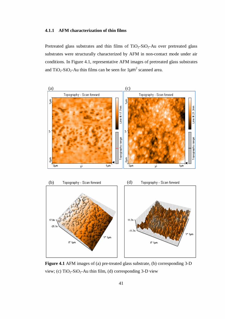
41
4.1.1 AFM characterization of thin films
Pretreated glass substrates and thin films of TiO2-SiO2-Au over pretreated glass
substrates were structurally characterized by AFM in non-contact mode under air
conditions. In Figure 4.1, representative AFM images of pretreated glass substrates
and TiO2-SiO2-Au thin films can be seen for 1µm2 scanned area.
Figure 4.1 AFM images of (a) pre-treated glass substrate, (b) corresponding 3-D
view; (c) TiO2-SiO2-Au thin film, (d) corresponding 3-D view
(a) (c)
(b) (d)
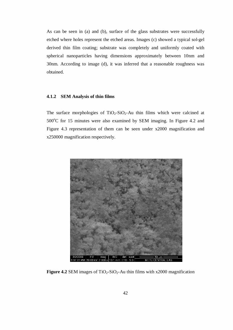
42
As can be seen in (a) and (b), surface of the glass substrates were successfully
etched where holes represent the etched areas. Images (c) showed a typical sol-gel
derived thin film coating; substrate was completely and uniformly coated with
spherical nanoparticles having dimensions approximately between 10nm and
30nm. According to image (d), it was inferred that a reasonable roughness was
obtained.
4.1.2 SEM Analysis of thin films
The surface morphologies of TiO2-SiO2-Au thin films which were calcined at
500oC for 15 minutes were also examined by SEM imaging. In Figure 4.2 and
Figure 4.3 representation of them can be seen under x2000 magnification and
x250000 magnification respectively.
Figure 4.2 SEM images of TiO2-SiO2-Au thin films with x2000 magnification
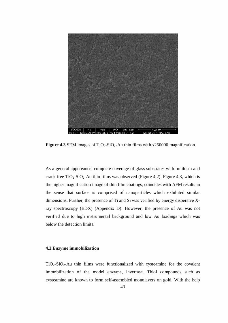
43
Figure 4.3 SEM images of TiO2-SiO2-Au thin films with x250000 magnification
As a general appereance, complete coverage of glass substrates with uniform and
crack free TiO2-SiO2-Au thin films was observed (Figure 4.2). Figure 4.3, which is
the higher magnification image of thin film coatings, coincides with AFM results in
the sense that surface is comprised of nanoparticles which exhibited similar
dimensions. Further, the presence of Ti and Si was verified by energy dispersive X-
ray spectroscopy (EDX) (Appendix D). However, the presence of Au was not
verified due to high instrumental background and low Au loadings which was
below the detection limits.
4.2 Enzyme immobilization
TiO2-SiO2-Au thin films were functionalized with cysteamine for the covalent
immobilization of the model enzyme, invertase. Thiol compounds such as
cysteamine are known to form self-assembled monolayers on gold. With the help
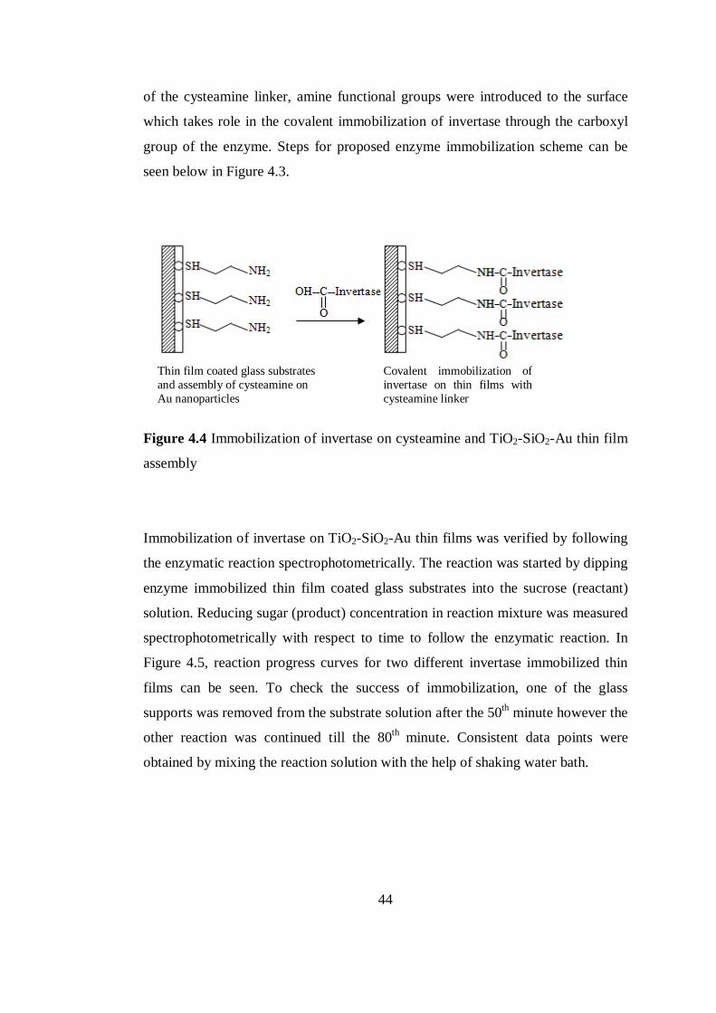
44
of the cysteamine linker, amine functional groups were introduced to the surface
which takes role in the covalent immobilization of invertase through the carboxyl
group of the enzyme. Steps for proposed enzyme immobilization scheme can be
seen below in Figure 4.3.
Figure 4.4 Immobilization of invertase on cysteamine and TiO2-SiO2-Au thin film
assembly
Immobilization of invertase on TiO2-SiO2-Au thin films was verified by following
the enzymatic reaction spectrophotometrically. The reaction was started by dipping
enzyme immobilized thin film coated glass substrates into the sucrose (reactant)
solution. Reducing sugar (product) concentration in reaction mixture was measured
spectrophotometrically with respect to time to follow the enzymatic reaction. In
Figure 4.5, reaction progress curves for two different invertase immobilized thin
films can be seen. To check the success of immobilization, one of the glass
supports was removed from the substrate solution after the 50th minute however the
other reaction was continued till the 80th minute. Consistent data points were
obtained by mixing the reaction solution with the help of shaking water bath.
Thin film coated glass substrates and assembly of cysteamine on Au nanoparticles
Covalent immobilization of invertase on thin films with cysteamine linker
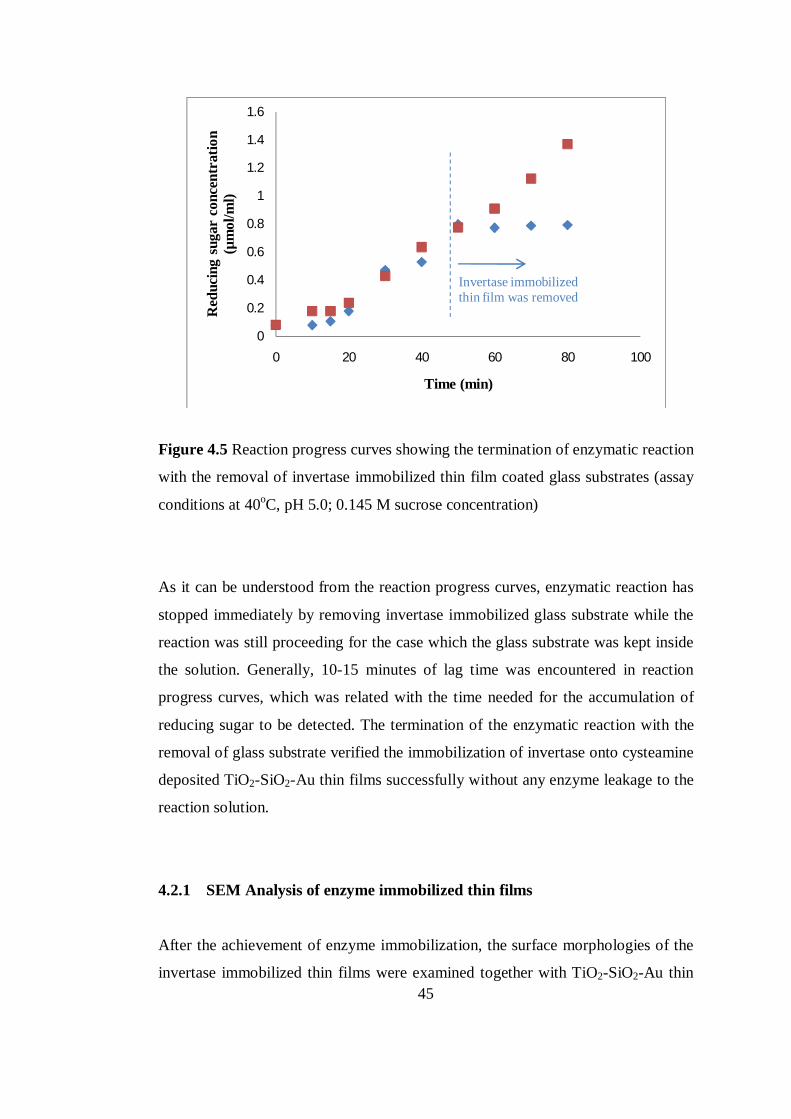
45
Figure 4.5 Reaction progress curves showing the termination of enzymatic reaction
with the removal of invertase immobilized thin film coated glass substrates (assay
conditions at 40oC, pH 5.0; 0.145 M sucrose concentration)
As it can be understood from the reaction progress curves, enzymatic reaction has
stopped immediately by removing invertase immobilized glass substrate while the
reaction was still proceeding for the case which the glass substrate was kept inside
the solution. Generally, 10-15 minutes of lag time was encountered in reaction
progress curves, which was related with the time needed for the accumulation of
reducing sugar to be detected. The termination of the enzymatic reaction with the
removal of glass substrate verified the immobilization of invertase onto cysteamine
deposited TiO2-SiO2-Au thin films successfully without any enzyme leakage to the
reaction solution.
4.2.1 SEM Analysis of enzyme immobilized thin films
After the achievement of enzyme immobilization, the surface morphologies of the
invertase immobilized thin films were examined together with TiO2-SiO2-Au thin
0
0.2
0.4
0.6
0.8
1
1.2
1.4
1.6
0 20 40 60 80 100
Red
ucin
g su
gar
conc
entr
atio
n (µ
mol
/ml)
Time (min)
Invertase immobilized thin film was removed
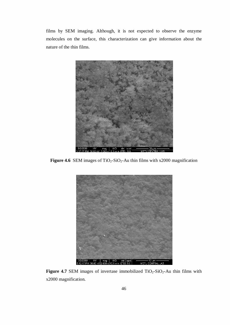
46
films by SEM imaging. Although, it is not expected to observe the enzyme
molecules on the surface, this characterization can give information about the
nature of the thin films.
Figure 4.6 SEM images of TiO2-SiO2-Au thin films with x2000 magnification
Figure 4.7 SEM images of invertase immobilized TiO2-SiO2-Au thin films with
x2000 magnification.
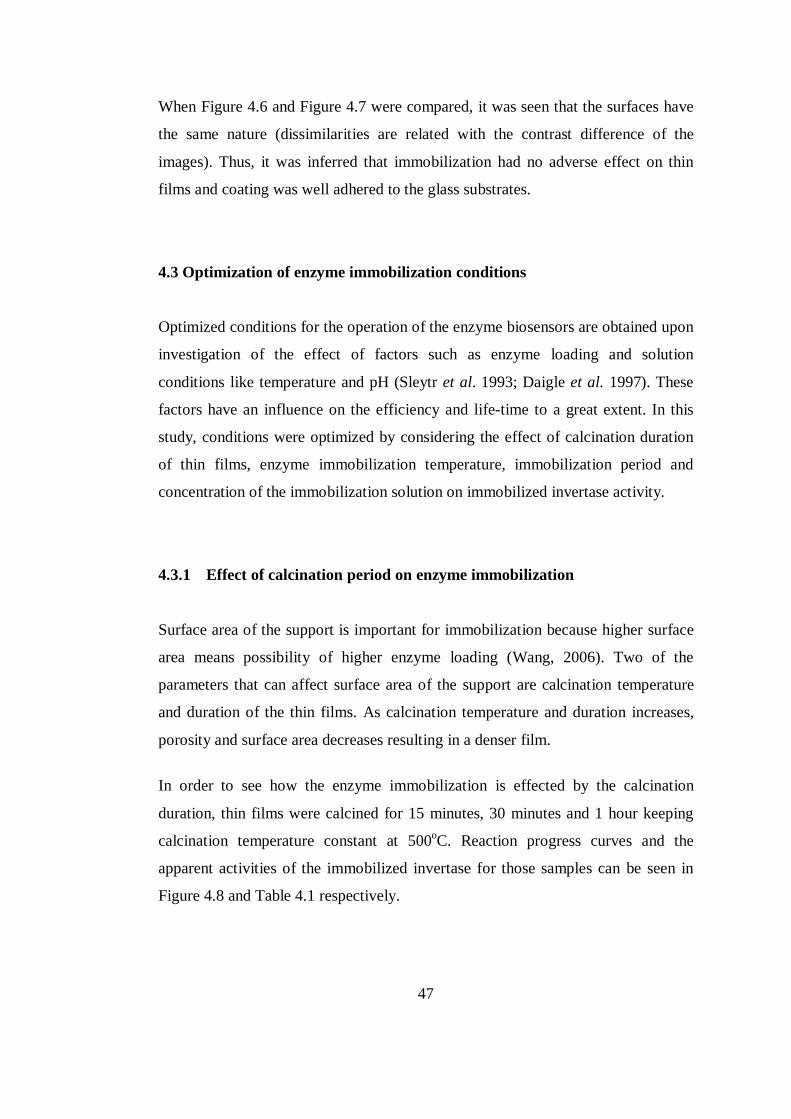
47
When Figure 4.6 and Figure 4.7 were compared, it was seen that the surfaces have
the same nature (dissimilarities are related with the contrast difference of the
images). Thus, it was inferred that immobilization had no adverse effect on thin
films and coating was well adhered to the glass substrates.
4.3 Optimization of enzyme immobilization conditions
Optimized conditions for the operation of the enzyme biosensors are obtained upon
investigation of the effect of factors such as enzyme loading and solution
conditions like temperature and pH (Sleytr et al. 1993; Daigle et al. 1997). These
factors have an influence on the efficiency and life-time to a great extent. In this
study, conditions were optimized by considering the effect of calcination duration
of thin films, enzyme immobilization temperature, immobilization period and
concentration of the immobilization solution on immobilized invertase activity.
4.3.1 Effect of calcination period on enzyme immobilization
Surface area of the support is important for immobilization because higher surface
area means possibility of higher enzyme loading (Wang, 2006). Two of the
parameters that can affect surface area of the support are calcination temperature
and duration of the thin films. As calcination temperature and duration increases,
porosity and surface area decreases resulting in a denser film.
In order to see how the enzyme immobilization is effected by the calcination
duration, thin films were calcined for 15 minutes, 30 minutes and 1 hour keeping
calcination temperature constant at 500oC. Reaction progress curves and the
apparent activities of the immobilized invertase for those samples can be seen in
Figure 4.8 and Table 4.1 respectively.
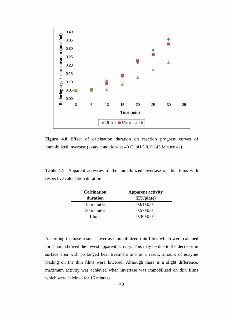
48
Figure 4.8 Effect of calcination duration on reaction progress curves of
immobilized invertase (assay conditions at 40oC, pH 5.0, 0.145 M sucrose)
Table 4.1 Apparent activities of the immobilized invertase on thin films with
respective calcination duration
Calcination
duration Apparent activity
(EU/plate) 15 minutes 0.61±0.01 30 minutes 0.57±0.01
1 hour 0.36±0.01
According to those results, invertase immobilized thin films which were calcined
for 1 hour showed the lowest apparent activity. This may be due to the decrease in
surface area with prolonged heat treatment and as a result, amount of enzyme
loading on the thin films were lowered. Although there is a slight difference,
maximum activity was achieved when invertase was immobilized on thin films
which were calcined for 15 minutes.
0.00
0.05
0.10
0.15
0.20
0.25
0.30
0.35
0.40
0 5 10 15 20 25 30 35Red
ucin
g su
gar
conc
entr
atio
n (µ
mol
/ml)
Time (min)
15 min 30 min 1h
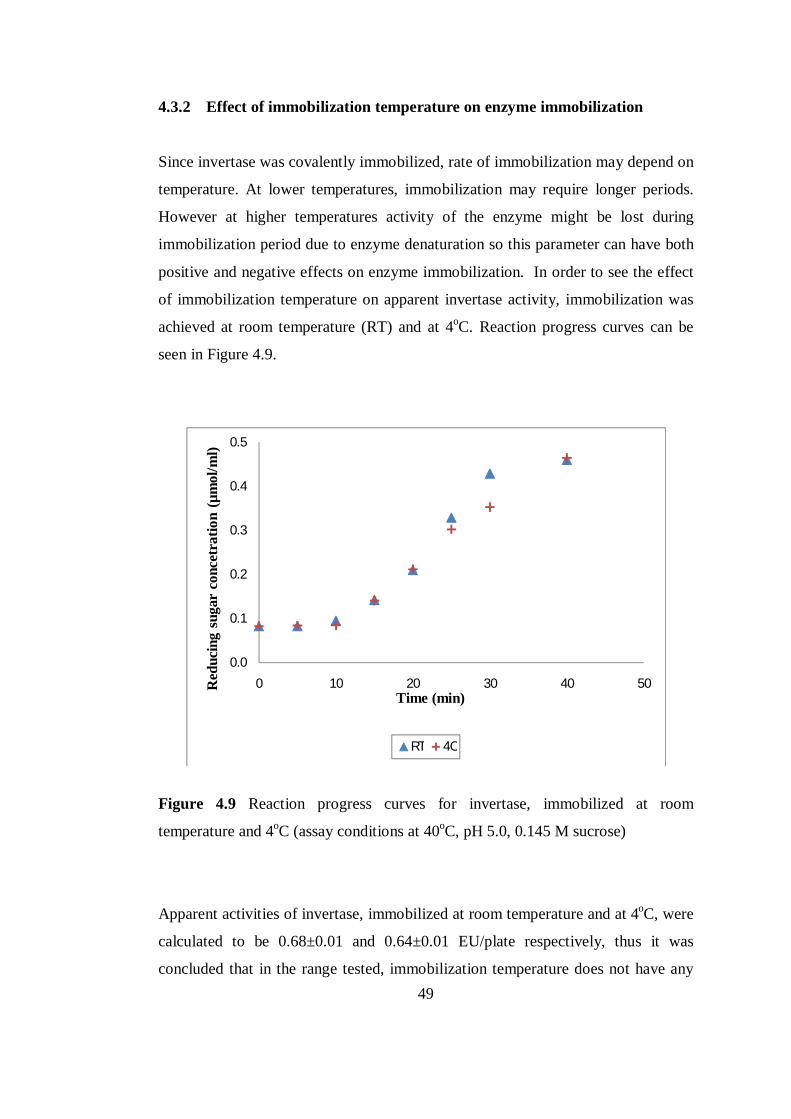
49
4.3.2 Effect of immobilization temperature on enzyme immobilization
Since invertase was covalently immobilized, rate of immobilization may depend on
temperature. At lower temperatures, immobilization may require longer periods.
However at higher temperatures activity of the enzyme might be lost during
immobilization period due to enzyme denaturation so this parameter can have both
positive and negative effects on enzyme immobilization. In order to see the effect
of immobilization temperature on apparent invertase activity, immobilization was
achieved at room temperature (RT) and at 4oC. Reaction progress curves can be
seen in Figure 4.9.
Figure 4.9 Reaction progress curves for invertase, immobilized at room
temperature and 4oC (assay conditions at 40oC, pH 5.0, 0.145 M sucrose)
Apparent activities of invertase, immobilized at room temperature and at 4oC, were
calculated to be 0.68±0.01 and 0.64±0.01 EU/plate respectively, thus it was
concluded that in the range tested, immobilization temperature does not have any
0.0
0.1
0.2
0.3
0.4
0.5
0 10 20 30 40 50Red
ucin
g su
gar
conc
etra
tion
(µm
ol/m
l)
Time (min)
RT 4C
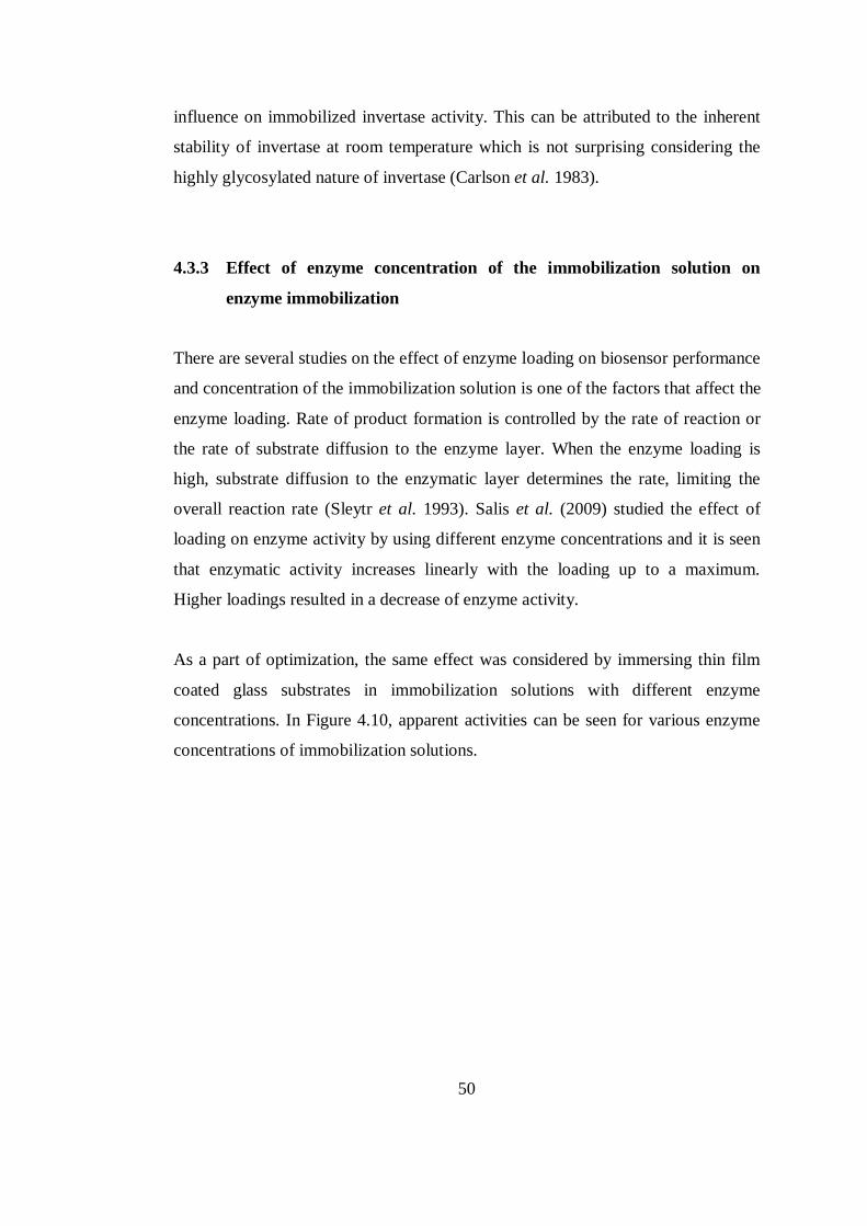
50
influence on immobilized invertase activity. This can be attributed to the inherent
stability of invertase at room temperature which is not surprising considering the
highly glycosylated nature of invertase (Carlson et al. 1983).
4.3.3 Effect of enzyme concentration of the immobilization solution on
enzyme immobilization
There are several studies on the effect of enzyme loading on biosensor performance
and concentration of the immobilization solution is one of the factors that affect the
enzyme loading. Rate of product formation is controlled by the rate of reaction or
the rate of substrate diffusion to the enzyme layer. When the enzyme loading is
high, substrate diffusion to the enzymatic layer determines the rate, limiting the
overall reaction rate (Sleytr et al. 1993). Salis et al. (2009) studied the effect of
loading on enzyme activity by using different enzyme concentrations and it is seen
that enzymatic activity increases linearly with the loading up to a maximum.
Higher loadings resulted in a decrease of enzyme activity.
As a part of optimization, the same effect was considered by immersing thin film
coated glass substrates in immobilization solutions with different enzyme
concentrations. In Figure 4.10, apparent activities can be seen for various enzyme
concentrations of immobilization solutions.
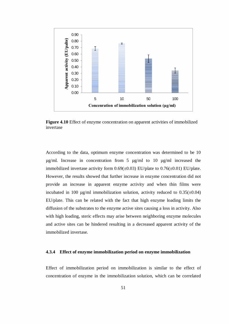
51
Figure 4.10 Effect of enzyme concentration on apparent activities of immobilized invertase
According to the data, optimum enzyme concentration was determined to be 10
µg/ml. Increase in concentration from 5 µg/ml to 10 µg/ml increased the
immobilized invertase activity form 0.69(±0.03) EU/plate to 0.76(±0.01) EU/plate.
However, the results showed that further increase in enzyme concentration did not
provide an increase in apparent enzyme activity and when thin films were
incubated in 100 µg/ml immobilization solution, activity reduced to 0.35(±0.04)
EU/plate. This can be related with the fact that high enzyme loading limits the
diffusion of the substrates to the enzyme active sites causing a loss in activity. Also
with high loading, steric effects may arise between neighboring enzyme molecules
and active sites can be hindered resulting in a decreased apparent activity of the
immobilized invertase.
4.3.4 Effect of enzyme immobilization period on enzyme immobilization
Effect of immobilization period on immobilization is similar to the effect of
concentration of enzyme in the immobilization solution, which can be correlated
0.00
0.10
0.20
0.30
0.40
0.50
0.60
0.70
0.80
0.90
5 10 50 100
App
aren
t act
ivity
(EU
/pal
te)
Concenration of immobilization solution (µg/ml)
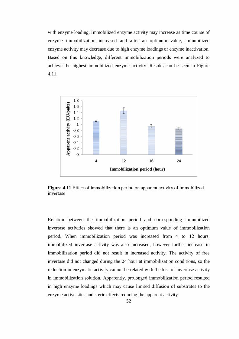
52
with enzyme loading. Immobilized enzyme activity may increase as time course of
enzyme immobilization increased and after an optimum value, immobilized
enzyme activity may decrease due to high enzyme loadings or enzyme inactivation.
Based on this knowledge, different immobilization periods were analyzed to
achieve the highest immobilized enzyme activity. Results can be seen in Figure
4.11.
Figure 4.11 Effect of immobilization period on apparent activity of immobilized invertase
Relation between the immobilization period and corresponding immobilized
invertase activities showed that there is an optimum value of immobilization
period. When immobilization period was increased from 4 to 12 hours,
immobilized invertase activity was also increased, however further increase in
immobilization period did not result in increased activity. The activity of free
invertase did not changed during the 24 hour at immobilization conditions, so the
reduction in enzymatic activity cannot be related with the loss of invertase activity
in immobilization solution. Apparently, prolonged immobilization period resulted
in high enzyme loadings which may cause limited diffusion of substrates to the
enzyme active sites and steric effects reducing the apparent activity.
0
0.2
0.4
0.6
0.8
1
1.2
1.4
1.6
1.8
4 12 16 24
App
aren
t act
ivity
(EU
/pal
te)
Immobilization period (hour)
53
4.4 Storage stability of invertase immobilized thin films
Enzyme stability issues are always of high significance in the production of a stable
and reproducible biosensor because practical applications can be hindered by poor
stability (Spain et al. 2008). In Figure 4.12, residual enzyme activity can be seen
with respect to storage time. When stored at 4oC in 0.1 M pH 5.0 sodium acetate
buffer, it was seen that invertase immobilized thin films retained 85% of their
initial activity after 4 weeks and more than 50% of their initial activity retained
after 9 weeks and free invertase lost its activity in two weeks. When compared with
similar studies from literature (covalent immobilization of invertase and the same
storage conditions) (Chen et al. 2000, Danisman et al. 2004), it was seen that
invertase immobilized on TiO2-SiO2-Au thin films showed quite good storage
stability. However, it is observed that when they were stored in dry conditions,
immobilized invertase activity diminished immediately.
Figure 4.12 Residual activity of immobilized invertase with respect to storage time
0102030405060708090
100
0 2 4 6 8 10
Res
idua
l act
ivity
(%)
Storage time (week)
wet dry
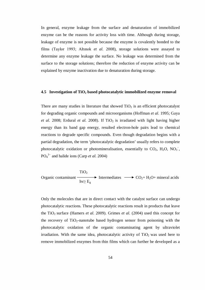
54
In general, enzyme leakage from the surface and denaturation of immobilized
enzyme can be the reasons for activity loss with time. Although during storage,
leakage of enzyme is not possible because the enzyme is covalently bonded to the
films (Taylor 1993; Altınok et al. 2008), storage solutions were assayed to
determine any enzyme leakage the surface. No leakage was determined from the
surface to the storage solutions; therefore the reduction of enzyme activity can be
explained by enzyme inactivation due to denaturation during storage.
4.5 Investigation of TiO2 based photocatalytic immobilized enzyme removal
There are many studies in literature that showed TiO2 is an efficient photocatalyst
for degrading organic compounds and microorganisms (Hoffman et al. 1995; Gaya
et al. 2008; Erdural et al. 2008). If TiO2 is irradiated with light having higher
energy than its band gap energy, resulted electron-hole pairs lead to chemical
reactions to degrade specific compounds. Even though degradation begins with a
partial degradation, the term ‘photocatalytic degradation’ usually refers to complete
photocatalytic oxidation or photomineralisation, essentially to CO2, H2O, NO3−,
PO43− and halide ions (Carp et al. 2004)
Organic contaminant Intermediates CO2+ H2O+ mineral acids
Only the molecules that are in direct contact with the catalyst surface can undergo
photocatalytic reactions. These photocatalytic reactions result in products that leave
the TiO2 surface (Hamers et al. 2009). Grimes et al. (2004) used this concept for
the recovery of TiO2-nanotube based hydrogen sensor from poisoning with the
photocatalytic oxidation of the organic contaminating agent by ultraviolet
irradiation. With the same idea, photocatalytic activity of TiO2 was used here to
remove immobilized enzymes from thin films which can further be developed as a
TiO2 hv≥ Eg
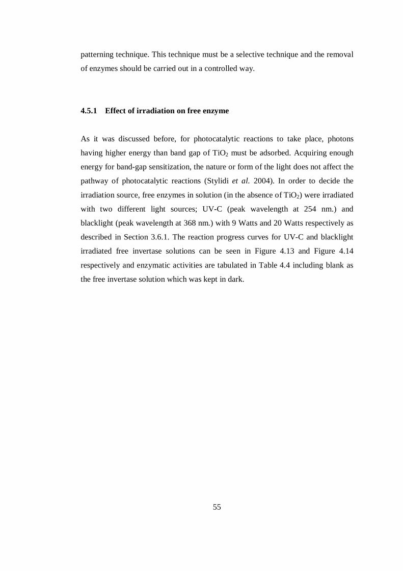
55
patterning technique. This technique must be a selective technique and the removal
of enzymes should be carried out in a controlled way.
4.5.1 Effect of irradiation on free enzyme
As it was discussed before, for photocatalytic reactions to take place, photons
having higher energy than band gap of TiO2 must be adsorbed. Acquiring enough
energy for band-gap sensitization, the nature or form of the light does not affect the
pathway of photocatalytic reactions (Stylidi et al. 2004). In order to decide the
irradiation source, free enzymes in solution (in the absence of TiO2) were irradiated
with two different light sources; UV-C (peak wavelength at 254 nm.) and
blacklight (peak wavelength at 368 nm.) with 9 Watts and 20 Watts respectively as
described in Section 3.6.1. The reaction progress curves for UV-C and blacklight
irradiated free invertase solutions can be seen in Figure 4.13 and Figure 4.14
respectively and enzymatic activities are tabulated in Table 4.4 including blank as
the free invertase solution which was kept in dark.
56
Figure 4.13 Reaction progress curves for UV-C irradiated free invertase (assay
conditions at 40oC, pH 5.0, 0.145 M sucrose)
Figure 4.14 Reaction progress curves for blacklight irradiated free invertase (assay
conditions at 40oC, pH 5.0, 0.145 M sucrose)
0.0
0.1
0.2
0.3
0.4
0.5
0.6
0 2 4 6 8 10 12
Red
ucin
g su
gar
conc
entr
atio
n (µ
mol
/ml)
Time (min)
Blank 0.5 h 2 h
0
0.05
0.1
0.15
0.2
0.25
0.3
0.35
0 2 4 6 8 10 12
Red
ucin
g su
gar
conc
entr
atio
n (µ
mol
/ml)
Time (min)
Blank 0.5h 2h
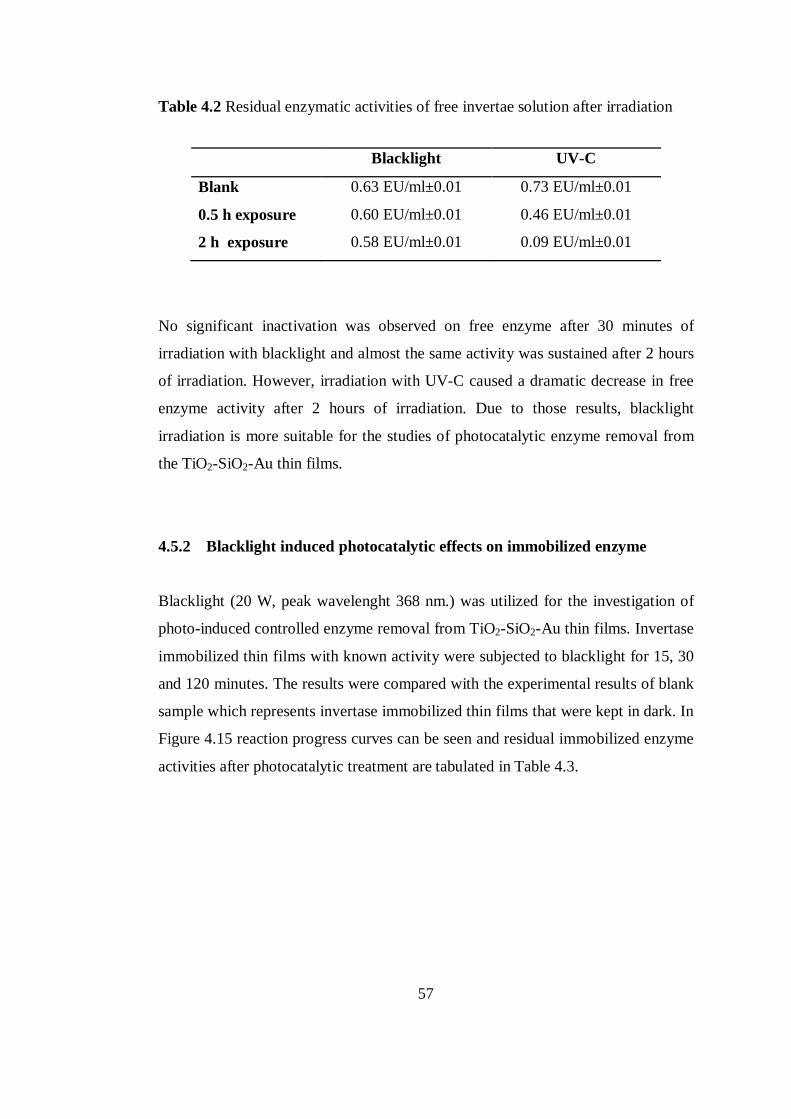
57
Table 4.2 Residual enzymatic activities of free invertae solution after irradiation
Blacklight UV-C
Blank 0.63 EU/ml±0.01 0.73 EU/ml±0.01
0.5 h exposure 0.60 EU/ml±0.01 0.46 EU/ml±0.01
2 h exposure 0.58 EU/ml±0.01 0.09 EU/ml±0.01
No significant inactivation was observed on free enzyme after 30 minutes of
irradiation with blacklight and almost the same activity was sustained after 2 hours
of irradiation. However, irradiation with UV-C caused a dramatic decrease in free
enzyme activity after 2 hours of irradiation. Due to those results, blacklight
irradiation is more suitable for the studies of photocatalytic enzyme removal from
the TiO2-SiO2-Au thin films.
4.5.2 Blacklight induced photocatalytic effects on immobilized enzyme
Blacklight (20 W, peak wavelenght 368 nm.) was utilized for the investigation of
photo-induced controlled enzyme removal from TiO2-SiO2-Au thin films. Invertase
immobilized thin films with known activity were subjected to blacklight for 15, 30
and 120 minutes. The results were compared with the experimental results of blank
sample which represents invertase immobilized thin films that were kept in dark. In
Figure 4.15 reaction progress curves can be seen and residual immobilized enzyme
activities after photocatalytic treatment are tabulated in Table 4.3.
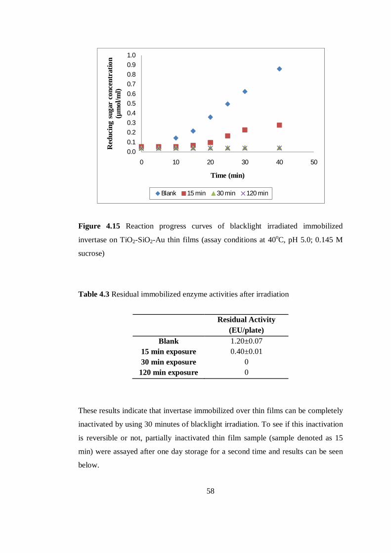
58
Figure 4.15 Reaction progress curves of blacklight irradiated immobilized
invertase on TiO2-SiO2-Au thin films (assay conditions at 40oC, pH 5.0; 0.145 M
sucrose)
Table 4.3 Residual immobilized enzyme activities after irradiation
Residual Activity
(EU/plate) Blank 1.20±0.07
15 min exposure 0.40±0.01 30 min exposure 0
120 min exposure 0
These results indicate that invertase immobilized over thin films can be completely
inactivated by using 30 minutes of blacklight irradiation. To see if this inactivation
is reversible or not, partially inactivated thin film sample (sample denoted as 15
min) were assayed after one day storage for a second time and results can be seen
below.
0.0
0.1
0.2
0.3
0.4
0.5
0.6
0.7
0.8
0.9
1.0
0 10 20 30 40 50
Red
ucin
g su
gar
conc
entr
atio
n (µ
mol
/ml)
Time (min)
Blank 15 min 30 min 120 min
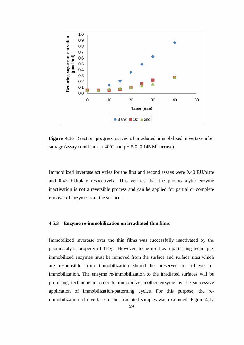
59
Figure 4.16 Reaction progress curves of irradiated immobilized invertase after
storage (assay conditions at 40oC and pH 5.0, 0.145 M sucrose)
Immobilized invertase activities for the first and second assays were 0.40 EU/plate
and 0.42 EU/plate respectively. This verifies that the photocatalytic enzyme
inactivation is not a reversible process and can be applied for partial or complete
removal of enzyme from the surface.
4.5.3 Enzyme re-immobilization on irradiated thin films
Immobilized invertase over the thin films was successfully inactivated by the
photocatalytic property of TiO2. However, to be used as a patterning technique,
immobilized enzymes must be removed from the surface and surface sites which
are responsible from immobilization should be preserved to achieve re-
immobilization. The enzyme re-immobilization to the irradiated surfaces will be
promising technique in order to immobilize another enzyme by the successive
application of immobilization-patterning cycles. For this purpose, the re-
immobilization of invertase to the irradiated samples was examined. Figure 4.17
0.00.10.20.30.40.50.60.70.80.91.0
0 10 20 30 40 50
Red
ucin
g su
garc
once
ntra
tion
(µm
ol/m
l)
Time (min)
Blank 1st 2nd
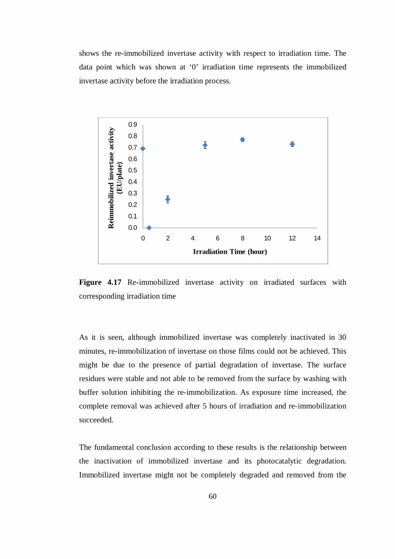
60
shows the re-immobilized invertase activity with respect to irradiation time. The
data point which was shown at ‘0’ irradiation time represents the immobilized
invertase activity before the irradiation process.
Figure 4.17 Re-immobilized invertase activity on irradiated surfaces with
corresponding irradiation time
As it is seen, although immobilized invertase was completely inactivated in 30
minutes, re-immobilization of invertase on those films could not be achieved. This
might be due to the presence of partial degradation of invertase. The surface
residues were stable and not able to be removed from the surface by washing with
buffer solution inhibiting the re-immobilization. As exposure time increased, the
complete removal was achieved after 5 hours of irradiation and re-immobilization
succeeded.
The fundamental conclusion according to these results is the relationship between
the inactivation of immobilized invertase and its photocatalytic degradation.
Immobilized invertase might not be completely degraded and removed from the
0.0
0.1
0.2
0.3
0.4
0.5
0.6
0.7
0.8
0.9
0 2 4 6 8 10 12 14
Rei
mm
obili
zed
inve
rtas
e ac
tivity
(E
U/p
late
)
Irradiation Time (hour)
61
surface although being inactivated. Despite the possibility of re-immobilizing
invertase onto the residues which occupied the surface after irradiation, it is very
plausible that immobilized invertase was photocatalytically degraded and removed
from the surface after sufficient exposure which made the re-immobilization of
invertase to the irradiated thin films possible. With this concept, new application
area of photocatalytic activity of TiO2 in biosensor technology can be introduced.
By choosing appropriate irradiation power and time, the immobilized enzyme over
the surface can be removed with controlled way and another enzyme might be
immobilized. Thus, the production of enzyme arrays is viable with this technique.
Generally, TiO2 thin films and powders are used in biosensor applications because
of their non-toxicity, high biocompatibility and good retention of biological activity
for protein binding. Also their high surface area, optical transparency and
conductivity are preferred properties for bioanalytical applications (Topoglidis et
al. 1998). In literature, the photocatalytic activitiy of TiO2 in the presence of
enzymes was used to improve the response of the biosensor (Ganadu et al. 2002;
Zu et al. 2009). It was reported that the sensitivity of detection increased when the
enzyme immobilized TiO2 surfaces were UV irradiated due to the additional
capture of electrons from the photoexcited TiO2. However, inactivation of enzymes
in the presence of photoexcited TiO2 is perceived as a drawback (Ganadu et al.
2002; Zu et al. 2009).
Use of TiO2 in the photopatterning of biomolecules for biosensor applications is a
promising technique. Very recently, TiO2 was utilized for the photo-patterning of
biomolecules with the UV initiated photochemical grafting of functional groups by
the exclusion of water and O atoms (Li et al. 2009; Franking et al. 2009). However,
our study showed the possibility of photocatalytic removal of immobilized
enzymes from the thin films without destructing the immobilization capability
which can be utilized for the preparation of enzyme site arrays for biosensor
applications. The representative sketch in Figure 4.18 was drawn to give an idea
about how the photocatalytic enzyme removal and re-immobilization can be
utilized to have enzyme patterns. As discussed in Section 2.7, photochemical
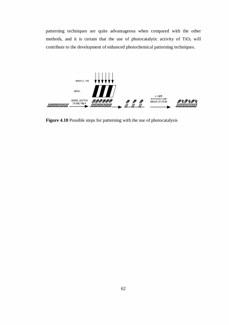
62
patterning techniques are quite advantageous when compared with the other
methods, and it is certain that the use of photocatalytic activity of TiO2 will
contribute to the development of enhanced photochemical patterning techniques.
Figure 4.18 Possible steps for patterning with the use of photocatalysis
63
CHAPTER 5
CONCLUSIONS
Within the scope of the present study, model enzyme invertase was successfully
immobilized on TiO2-SiO2-Au thin films. TiO2 based photocatalytic removal of
invertase by blacklight irradiation was achieved and invertase was re-immobilized
successfully to the irradiated thin films.
Well adhered and uniform TiO2-SiO2-Au thin film coatings were obtained on glass
substrates. TiO2-SiO2-Au thin films were functionalized with amine groups by
cysteamine linker and the immobilization of model enzyme invertase was achieved.
The immobilized invertase activity was found independent from the immobilization
temperature within the range tested. The optimum enzyme concentration and
period for immobilization was determined as 10µg/ml and 12 hours respectively.
With the optimized conditions, invertase immobilized thin films exhibited high
storage stability retaining more than 50% of their initial activity after 9 weeks.
The immobilized invertase over thin films was completely and irreversibly
inactivated with 30 minutes of blacklight (368 nm.) irradiation by the
photocatalytic activity of TiO2-SiO2-Au thin films. Invertase was re-immobilized to
the irradiated thin films and initial immobilized invertase activity (before the
irradiation) was attained when the invertase was re-immobilized to thin films that
were irradiated for 5 hours. Photocatalysis-reimmobilization cycles can pave the
way to new studies on enzyme patterning with the use of photocatalytic activity of
TiO2.
64
REFERENCES
Altınok, H., Aksoy, S., Tümtürk, H., Hasırcı, N. (2007), Covalent immobilization
of invertase on chemically activated poly (styrene-2-hydroxyethyl methacrylate)
microbeads, Journal of Food Biochemistry, 32, 299-315
Bennani, J., Dillert, R., Gesing, T. M., Bahnemann, D. (2009), Physical properties,
stability, and photocatalytic activity of transparent TiO2/SiO2 films, Separation and
Purification Technology, 67, 173-179
Bickerstaff, F.G. (1997), Immobilization of Enzymes and Cells, Humana Press,
New Jersey
Bhatia, S.K (1989), Use of thiol-terminated silanes and heterobifunctional cross
linkers for immobilization of antibodies on silica surfaces, Analytical Biochemistry,
178, 408-413
Bornside, D.E., Macosko, C.W., Scriven L.E. (1987), Method for compensating
film height modulations in spin coating of a resist film layer, Journal of Imaging
Technology, 13, 122-130
Branden, C., Tooze, J. (1999), Introduction to Protein Structure, Garland
Publishing, New York
Brinker, C.J., Scherer, G.W. (1990), Sol–Gel Science: The Physics and Chemistry
of Sol–Gel Processing, Academic Press, San Diego
Carp, O., Reller, A., Huisman, C.L. (2004), Photoinduced reactivity of titanium
dioxide, Progress in Solid State Chemistry, 32, 33–177
65
Chavez, P.F., Rodriguez, L., Diaz, J., Delgada, J.M., Cremata, J.A. (1997),
Purification and characterization of an invertase form Candida utilis: Comparison
with natural and recombinant yeast invertases, Journal of Biotechnology, 53, 67-74
Chen, Y., Kang, E.T., Neoh, K.G., Tan, K.L. (2000), Covalent immobilization of
invertase onto the surface-modified polyaniline from graft copolymerization with
acrylic acid, European Polymer Journal, 36, 2095-2103
Chen, X., Dong, J (2003), Sol-gel-derived titanium oxide/copolymer composite
based glucose biosensor, Biosensors and Bioelectronics, 18, 999-1004
Cullum, B., Vo-Dihn, T. (2000), Biosensors and biochips: Advances in biological
and medical diagnostics, Fresenius' Journal of Analytical Chemistry, 366, 540–
551
Daigle, F., Leech D. (1997), Reagentless tyrosinase enzyme electrodes: Effects of
enzyme loading, electrolyte pH, ionic strenght and temperature, Analytic
Chemistry, 69, 4108-4112
Danisman, T., Tan, S., Kacar, Y., Ergene, A. (2004), Covalent immobilization of
imvertase on microporous pHEMA-GMA membrane, Food Chemistry, 85, 461–
466
Davis, F., Higson, S.P.J (2005), Structured thin films as functional components
within biosensors, Biosensors and Bioelectronics, 21, 1–20
Delamarche, E., Sundarababu, G., Biebuyck, H., Mathieu, J. (2006),
Immobilization of Antibodies on a Photoactive Self-Assembled Monolayer on
Gold, Langmuir, 12, 1997-2006
Eggins, B.R. (2002), Chemical sensors and biosensors, John Wiley, New York
66
Erdural, B.K., Yurum, A., Bakir, U., Karakas, G. (2008), Hydrothermal Synthesis
of Nanostructured TiO2 Particles and Characterization of Their Photocatalytic
Antimicrobial Activity, Journal of Nanoscience and Nanotechnology, 8, 878-886
Ersöz, T.İ. (2009), Application of semi conductor films over glass/ceramic surfaces
and their low temperature photocatalytic activity, MSc.Thesis Dissertation, Middle
East Technical University
Franking, R.A., Landis, E.C., Hamers, R.J. (2009), Highly Stable Molecular Layers
on Nanocrystalline Anatase TiO2 through Photochemical Grafting, Langmuir.
Ganadu, M.L., Andreotti, L., Vitali, I., Maldotti, A., Molinari, A., Mura, G.M.
(2002), Glucose oxidase catalyses the reduction of O2 to H2O2 in the presence of
irradiated TiO2 and isopropyl alcohol, Photochemical&Photobiological Sciences,1,
951–954
Gaya, U.I., Abdullah, A.H. (2008), Heterogeneous photocatalytic degradation of
organic contaminants over titanium dioxide: A review of fundamentals, progress
and problems, Journal of Photochemistry and Photobiology C: Photochemistry
Reviews 9, 1-12
Guan, K. (2005), Relationship between photocatalytic activity, hydrophilicity and
self-cleaning effect of TiO2/SiO2 films, Surface and Coatings Technology 191,
155-160
Hamers, J.R., Kim, H., Landis, C.E., Franking, R., Li, B. (2009), Photochemical
Grafting and Patterning of Biomolecular Layers onto TiO2 thin films, Applied
Materials and Interfaces, 1013-1022
Han, F., Kambala, R., Srinivasan, M., Rajarathnam, D., Naidu, R. (2009), Tailored
titanium dioxide photocatalysts for the degradation of organic dyes in wastewater
treatment: A review, Applied Catalysis A: General, 359, 25–40APPENDICES
67
Henke, L., Noemi, N., Krull, U. (2002), An AFM determination of the effects on
surface roughness caused by cleaning of fused silica and glass substrates in the
process of optical biosensor preparation, Biosensors and Bioelectronics, 17,547-
555
Hoffmann M.R., Martin S.T., Choi W., Bahnemann D.W. (1995), Environmental
Applications of Semiconductor Photocatalysis, Chemistry Reviews, 95, 69-96
Jianrong, C., Yuqing, M., Nongyue, H., Sijiao, L. (2004), Nanotechnology and
biosensors, Biotechnology Advances, 22, 505–518
Kaplan, Ö. (1996), Stabilization of yeast invertase, MSc.Thesis Dissertation,
Middle East Technical University
Kim, D.J., Hahn, S.H., Oh, S.H. and Kim, E.J. (2002), Influence of calcinations
temperature on structural and optical properties of TiO2 thin films prepared by sol-
gel dip coating, Materials Letters, 57, 335
Koç, B. (2009), Production of titanium dioxide thin films with improved
photocatalytic activity: The use of bacteria as 3D templates, MSc.Thesis
Dissertation, Middle East Technical University
Kumar, C.S.S.R (2007), Nanomaterials in biosensors, Wiley-VCH, Weinheim
Kwon, C.H., Kim, H.J., Jung, S.I., Hyunmin, S., Yoon, H.K. (2003), Preparation
and characterization of TiO2–SiO2 nano-composite thin films, Ceramics
International, 29, 851–856
Li, B., Franking, R., Landis, E.C., Kim, H., Hamers R.J. (2009), Photochemical
grafting and patterning of biomolecular layers onto TiO2 thin films, Applied
Materials and Interfaces
68
Li, N., Ho, C.M. (2008), Patterning Functional Proteins with High Selectivity for
Biosensor Applications, Journal of the Association for Laboratory Automation, 13,
237-242
Li X.Z. and Li F.B. (2001), Study of Au/Au3+-TiO2 photocatalysts toward visible
photo-oxidation for water and wastewater treatment, Environmental Science and
Technology, 35, 2381-2387
Love, C.J., Estroff, L.A., Kriebel, J.K., Nuzzo, G.R., Whitesides, G.M. (2005),
Self-assembled monolayers of thiolates on metals as a form of nanotechnology,
Chemical Reviews, 105, 1103-1170
Lowe, R.C., Gizeli, E. (2002), Biomolecular Sensors, Taylor&Francis Inc., London
Luo, X., Morrin, A., Killard, J., Smyth, M.R. (2006), Application of Nanoparticles
in Electrochemical Sensors and Biosensors, Electroanalysis, 18, 319-326
Mendes, R.K., Carvalhal R.F., Kubota L.T. (2008), Effects of different self-
assembled monolayers on enzyme immobilization procedures in peroxidase-based
biosensor development, Journal of Electroanalytical Chemistry, 612, 164–172
Mills, A., Le Hunte, S. (1997), An overview of semiconductor photocatalysis,
Journal of Photochemistry and Photobiology, 108, 1-35
Mor, K.G., Pishko, V.M., Varghese O.K., Carvalho, A.M., Grimes, A.G. (2004), A
room temperature TiO2-nanotube hydrogen sensor able to self-clean photoactively
from environmental contamination, Journal of Materials Research, 19, 628-634
Mutlu, S., Çökeliler, D., Shard, A., Goktas, H., Ozansoy, B., Mutlu, M. (2008),
Preparation and characterization of ethylenediamine and cysteamine plasma
polymerized films on piezoelectric quartz crystal surfaces for a biosensor, Thin
Solid Films, 516, 1249-1255
69
Perez, V.V. (2004), Synthesis of highly quenching fullerene derivatives for
biosensor applications, MSc.Thesis Dissertation, Massachusetts Institute of
Technology
Pourmand, M., Mohammadizadeh, M. R. (2008), Influence of temperature on TiO2
nanoparticles, Current Nanoscience, 4, 151-156
Pritchard, D.J, Morgan, H., Cooper, J.M. (1995), Micron-scale patterning of
biological molecules, Angewandte Chemie, 34, 91-93
Ratner, B.D. (1996), Surface diagnostics of plasma-treated materials, Kluwer
Academic Publishers, Netherlands.
Reichert, W.M., Blawas, A.S. (1998), Protein Patterning, Biomaterials, 19, 595-
609
Salis, A., Pisano, M., Monduzzi, M., Solinas, V., Sanjust, E. (2009), Laccase from
Pleurotus sajor-caju on functionalised SBA-15 mesoporous silica: Immobilisation
and use for the oxidation of phenolic compounds, Journal of Molecular Catalysis
B: Enzymatic, 58, 175-180
Schrijnemakers, K., Impens, N.R.E.N., Vansant, E.F. (1999), Deposition of a
titania coating on silica by means of the chemical surface coating, Langmuir, 15,
5807–5813
Schwartz, R., Schneller, T., Waser, R. (2004), Chemical solution deposition of
electronic oxide films, C. R. Chimie, 7, 433–461
Sever, K., Seki, Y., Güleç, H.A., Sarikanat, M., Mutlu, M., Tavman, I. (2009),
Preparation and characterization of thin films by plasma polymerization of
glycidoxypropyltrimethoxysilane at different plasma powers and exposure times,
Applied Surface Science, 255, 8450-8457
70
Shah, J., Wilkins, E. (2003), Electrochemical biosensors for detection of biological
warfare agents, Electroanalysis, 15, 157-167
Sigrist, H., Collioud, A., Clemence, J.F., Sundarababu, G. (1995), Surface
immobilization of biomolecules by light, Optical Engineering, 34, 2339-2348
Sleytr, U.B., Messner, P., Pum, D., Sara, M. (1993), Immobilized macromolecules:
Application potentials, Springer Series in Applied Biology
Spain, J.C., Brand, O., Seo, H. (2008), Three dimensional immobilization of β-
galactosidase on a silicon surface, Biotechnology and Bioengineering, 99, 261-26
Srere, P.A., Uyeda, K. (1986), Functional groups on enzymes suitable for binding
to matrices, Methods in Enzymology, 44, 11-19
Stylidi, M., Kondarides, D.I., Verykios, X.E. (2004), Visible light-induced
photocatalytic degradation of Acid Orange 7 in aqueous TiO2 suspensions, Applied
Catalysis B: Environmental, 47, 189-201
Taylor, F.R. (1993), Protein Immobilization: Fundamentals and Applications,
Marcel Dekker Inc., New York
Thevenot, D.R., Toth, K., Durst, R.A., Wilson, G.S. (2001), Electrochemical
biosensors: recommended definitions and classification, Biosensors &
Bioelectronics, 16, 121–131
Topoglidis, E., Cass, A.E.G., Gilardi, G., Sadeghi, S., Beaumont, N., Durrant, J.R
(1998), Protein adsorption on nanocrystalline TiO2 films: An immobilization
strategy for bioanalytical devices, Analytical Chemistry, 70, 5111-5113
71
Vepari, C.P., Kaplan, D.L. (2006), Covalently immobilized enzyme gradients
within three-dimensional porous scaffolds, Biotechnology and Bioengineering, 93,
1130-1137
Wang, P. (2006), Nanoscale biocatalyst systems, Current Opinion in
Biotechnology, 17, 574–579
Willner, I., Baron R. (2007), Integrated nanoparticle-biomolecule systems for
biosensing and bioelectronics, Biosensing&Bioelectronics, 22,1841-1852
Willner, I., Katz, E. (2000), Integration of layered redox proteins and conductive
supports for bioelectronic applications, Angewandte Chemie International Edition,
39, 1180-1218
Wright, D.J., Sommerdijk, A.J.M. (2001), Sol-gel materials, Chemistry and
Applications, Taylor&Francis Books Ltd., London
Yu, J., Zhao, X. (2002), The effect of SiO2 Addition on the Grain Size and
Photocatalytic Activity of TiO2 Thin Films, Journal of Sol-Gel Science and
Technology, 24, 95–103
Zhang, S., Wang, N., Yu, H., Niu, Y., Sun, C. (2004), Covalent attachment of
glucose oxidase to an Au electrode modified with gold nanoparticles for use as
glucose biosensor, Bioelectrochemistry, 67, 15-22
Zhang, Y., He, P., Hu, N. (2004), Horseradish peroxidase immobilized in TiO2
nanoparticle films on pyrolytic graphite electrodes: Direct electrochemistry and
bioelectrocatalysis, Electrochimica Act, 49, 1981-1988
Zhu, Y., Cao, H., Longhua, T., Yang, X., Li, C. (2009), Immobilization of
horseradish peroxidase in three-dimensional macroporous TiO2 matrices for
biosensor applications, Electrochimica Acta, 54, 2823–282
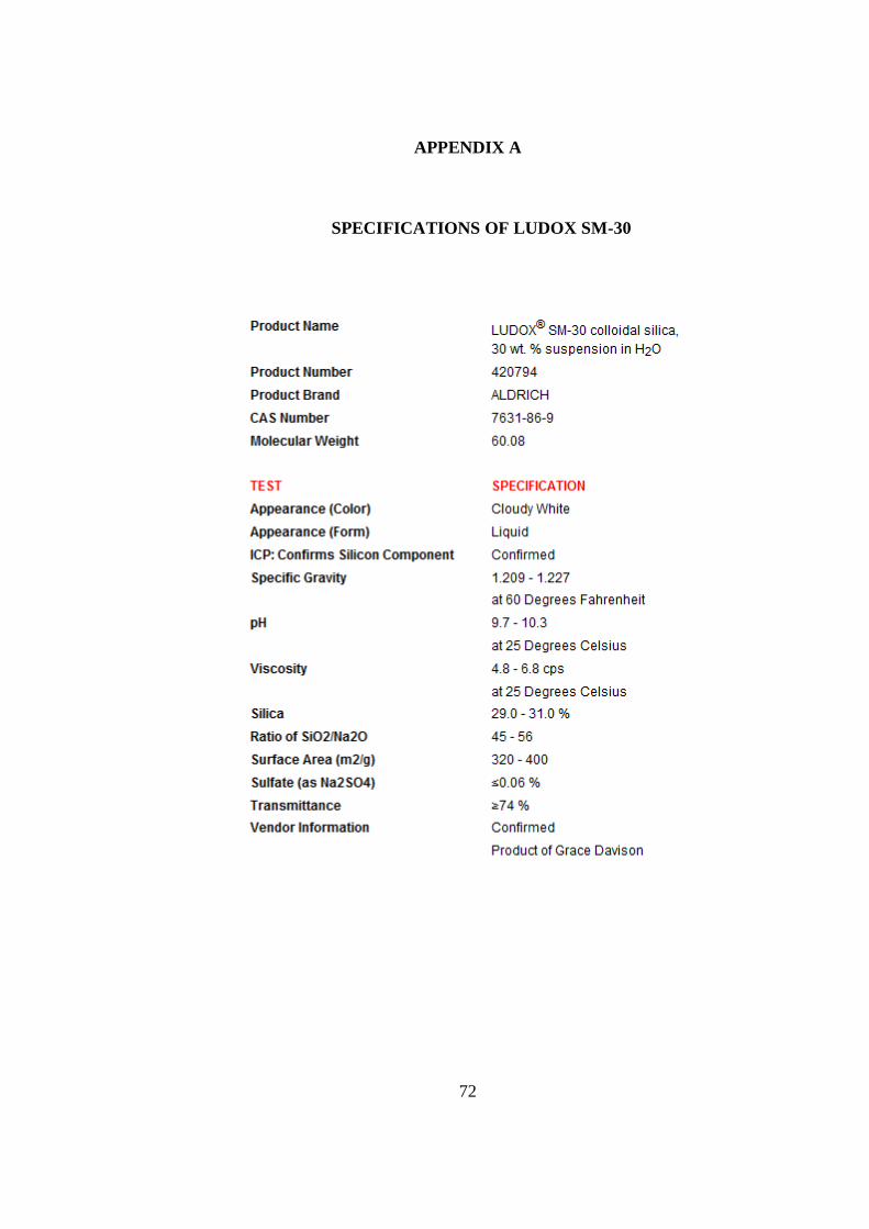
72
APPENDIX A
A. SPECIFICATIONS OF LUDOX SM-30
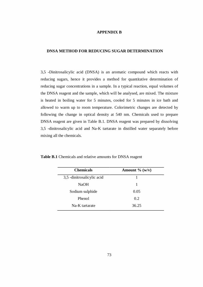
73
APPENDIX B
B. DNSA METHOD FOR REDUCING SUGAR DETERMINATION
3,5 -Dinitrosalicylic acid (DNSA) is an aromatic compound which reacts with
reducing sugars, hence it provides a method for quantitative determination of
reducing sugar concentrations in a sample. In a typical reaction, equal volumes of
the DNSA reagent and the sample, which will be analysed, are mixed. The mixture
is heated in boiling water for 5 minutes, cooled for 5 minutes in ice bath and
allowed to warm up to room temperature. Colorimetric changes are detected by
following the change in optical density at 540 nm. Chemicals used to prepare
DNSA reagent are given in Table B.1. DNSA reagent was prepared by dissolving
3,5 -dinitrosalicylic acid and Na-K tartarate in distilled water separately before
mixing all the chemicals.
Table B.1 Chemicals and relative amounts for DNSA reagent
Chemicals Amount % (w/v)
3,5 -dinitrosalicylic acid 1
NaOH 1
Sodium sulphide 0.05
Phenol 0.2
Na-K tartarate 36.25
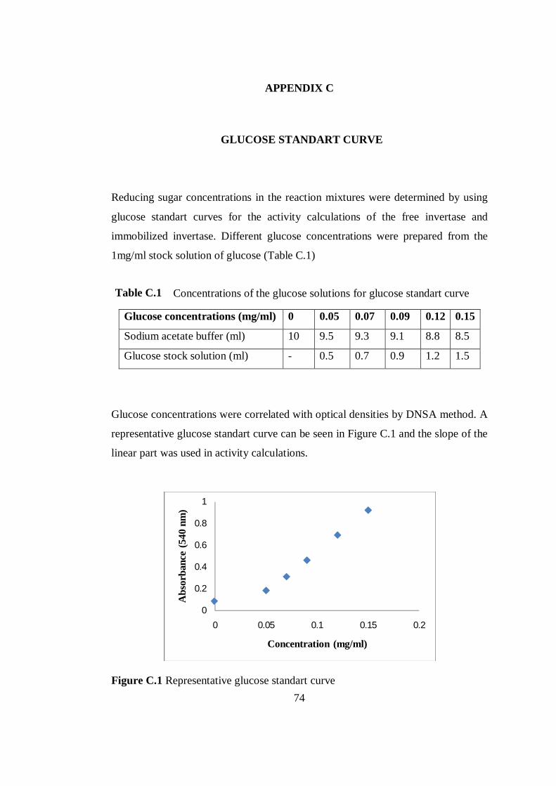
74
APPENDIX C
C. GLUCOSE STANDART CURVE
Reducing sugar concentrations in the reaction mixtures were determined by using
glucose standart curves for the activity calculations of the free invertase and
immobilized invertase. Different glucose concentrations were prepared from the
1mg/ml stock solution of glucose (Table C.1)
Glucose concentrations were correlated with optical densities by DNSA method. A
representative glucose standart curve can be seen in Figure C.1 and the slope of the
linear part was used in activity calculations.
Figure C.1 Representative glucose standart curve
0
0.2
0.4
0.6
0.8
1
0 0.05 0.1 0.15 0.2
Abs
orba
nce
(540
nm
)
Concentration (mg/ml)
Table C.1
Glucose concentrations (mg/ml) 0 0.05 0.07 0.09 0.12 0.15
Sodium acetate buffer (ml) 10 9.5 9.3 9.1 8.8 8.5
Glucose stock solution (ml) - 0.5 0.7 0.9 1.2 1.5
Concentrations of the glucose solutions for glucose standart curve
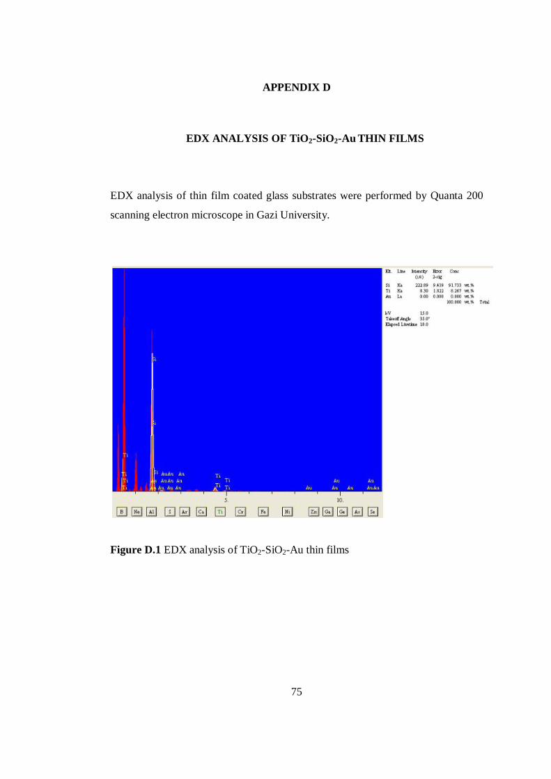
75
APPENDIX D
D. EDX ANALYSIS OF TiO2-SiO2-Au THIN FILMS
EDX analysis of thin film coated glass substrates were performed by Quanta 200
scanning electron microscope in Gazi University.
Figure D.1 EDX analysis of TiO2-SiO2-Au thin films