Embed Size (px)
Citation preview

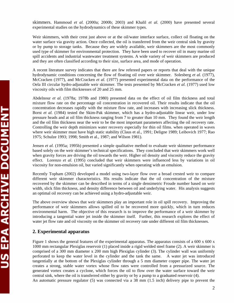
Enhanced oil spill recovery rate using the weir skimmer
A.H. Hammoud
Mechanical Engineering Department, Beirut Arab University,
P.O. Box: 11-5020, Beirut, Lebanon
Abstract Oil spills result in serious damage to the environment. Mechanical recovery using weir skimmers is one of
the most important techniques in combating oil spill. This paper discusses the enhancement of weir skimmer capacity on spill oil recovery by introducing a tangential water jet along the inside bottom of a weir chamber. The jet creates a strong, stable vortex inside the weir. The weir skimmer oil recovery rate increased as the water jet flow rate increases, the oil viscosity decreases and film thickness increases. The maximum oil recovery rate was attained when the weir crest was at the same level as the oil/water separation surface. Deploying containment booms to increase oil film thickness and using transfer pumps to increase oil recovery rates are recommended to maximize the enhanced weir skimmer’s effectiveness.
Keywords Weir skimmer, oil recovery rate, oil spills, marine pollution
Notation Q oil recovery rate, (cu.m. /hr). t oil film thickness, (mm). h submergence height, (mm). µ dynamic viscosity of oil, (N.s /m2). ñ density of oil, (kg/m3).
1. Introduction
Rapid economic growth has caused a substantial increase in oil consumption in recent decades. To meet market demand, oil producers have established a worldwide network of sea-going vessels that transport oil through major waterways. As a result, a significant amount of oil is spilled into seas from operational discharges of ships as well as from accidental tanker collisions and groundings. Oil spills resulting from tanker traffic, offshore drilling. Associated activities are likely to increase in years to come as demand for petroleum and petroleum products continue to rise. An oil spill accident is harmful to the ocean environment and the health of mankind. A major oil spill can cause serious damage to the fisheries and contaminate the shoreline (Wanga, et al., 2005). The threat of economic and environmental devastation from oil spill has lead to the development of a number of cleanup alternatives. These alternatives may be grouped into three separate categories: (i) dispersion of oil into the water column with chemical dispersants; (ii) sinking of oil with heavier-than-water materials; and (iii) recovery of oil from the sea surface with mechanical devices (boom and skimmer systems). All three methods remove oil from the water surface, but the first two methods simply transfer the oil from the water surface into the water column or onto the seabed. Both methods require the addition of chemical substances to the water, which in some cases may be toxic to marine biota. The third method uses floating booms to collect the oil, which then can be removed from the marine environment by skimmers. Mechanical cleanup techniques have proved to be an effective response strategy, as concluded by Tsocalis et al. (1994). Skimmers that use disks, belts, drums and brushes, recover oil from the water surface using the adhesive property of the skimmers’ surfaces. Turner et al, 1987, 1996, 1998, and 2000 presented extensive studies towards understanding and improving the hydrodynamic performance of disk
1
skimmers. Hammoud et al. (2000a; 2000b; 2003) and Khalil et al. (2000) have presented several experimental studies on the hydrodynamics of these skimmer types.
Weir skimmers, with their crest just above or at the oil/water interface surface, collect oil floating on the water surface via gravity action. Once collected, the oil is transferred from the weir central sink by gravity or by pump to storage tanks. Because they are widely available, weir skimmers are the most commonly used type of skimmer for environmental protection. They have been used to recover oil in many marine oil spill accidents and industrial wastewater treatment systems. A wide variety of weir skimmers are produced and they are often classified according to their size, surface area, and mode of operation.
A recent literature survey indicates that there are few refereed papers or reports that deal with the unique hydrodynamic conditions concerning the flow of floating oil over weir skimmer. Solesberg et al. (1977), McCracken (1977), and McCracken et al. (1977) presented experimental data on the performance of the Oela III circular hydro-adjustable weir skimmer. The tests presented by McCracken et al. (1977) used low viscosity oils with film thicknesses of 20 and 25 mm.
Abdelnour et al. (1978a; 1978b and 1980) presented data on the effect of oil film thickness and total mixture flow rate on the percentage oil concentration in recovered oil. Their results indicate that the oil concentration decreases rapidly with the mixture flow rate, and increases with increasing slick thickness. Borst et al. (1984) tested the Skim-Pak skimmer, which has a hydro-adjustable linear weir, under low pressure heads and at oil film thickness ranging from 7 to greater than 10 mm. They found the weir length and the oil film thickness near the weir to be the most important parameters affecting the oil recovery rate. Controlling the weir depth minimizes water recovery especially for thin oil films. when operated in waves where weir skimmer must have high static stability (Claus et al., 1991; Deligne 1989; Leibovich 1977; Rao 1975; Schulze 1993; 1998; Smith et al., 1987; and Wilson 1981).
Jensen et al. (1995a; 1995b) presented a simple qualitative method to evaluate weir skimmer performance based solely on the weir skimmer’s technical specifications. They concluded that weir skimmers work well when gravity forces are driving the oil towards the weir. Higher oil density and viscosity reduce the gravity effect. Lorenzo et al. (1995) concluded that weir skimmers were influenced less by variations in oil viscosity for non-emulsion oil, but varied significantly when operating with an emulsion.
Recently Topham (2002) developed a model using two-layer flow over a broad crested weir to compare different weir skimmer characteristics. His results indicate that the oil concentration of the mixture recovered by the skimmer can be described in terms of a single densimetric Froude number based on weir width, slick film thickness, and density difference between oil and underlying water. His analysis suggests an optimal oil recovery can be achieved using a hydro-adjustable weir.
The above overview shows that weir skimmers play an important role in oil spill recovery. Improving the performance of weir skimmers allows spilled oil to be recovered more quickly, which in turn reduces environmental harm. The objective of this research is to improve the performance of a weir skimmer by introducing a tangential water jet inside the skimmer itself. Further, this research explores the effect of water jet flow rate and oil viscosity on the skimmer oil recovery rate under different oil film thicknesses.
2. Experimental apparatus
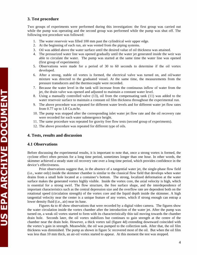
Figure 1 shows the general features of the experimental apparatus. The apparatus consists of a 600 x 600 x 1000 mm rectangular Plexiglas reservoir (1) placed inside a rigid welded steel frame (2). A weir skimmer is comprised of a 300 mm diameter x 200 mm high Plexiglas cylinder (3). The cylinder wall was uniformly perforated to keep the water level in the cylinder and the tank the same. A water jet was introduced tangentially at the bottom of the Plexiglas cylinder through a 5 mm diameter copper pipe. The water jet creates a strong, stable water vortex whose flow rates were controlled from a pressurized source. The generated vortex creates a cyclone, which forces the oil to flow over the water surface toward the weir central sink, where the oil is transferred either by gravity or by a pump to a graduated reservoir (4). An automatic pressure regulator (5) was connected via a 38 mm (1.5 inch) delivery pipe to prevent the
2
pump from running dry. A mechanical gage pressure (6), connected to the delivery pipe, is used to obtain the delivery pressure of the pump. Two electrical solenoid valves (7) allow flow to be directed either to the graduated vessel or to the main reservoir. A nozzle type flow meter (8) is connected between the differential pressure transducer (9) and a data acquisition recorder to measure and record the pump discharge automatically. A 1500 mm (h) x 240 mm (dia) graduated vessel (10) is used to measure the volume of recovered oil and the oil/water ratio. The recovered oil is transferred back to a 60-litre oil reservoir (11) located on the top of the test rig using a gear pump (12). A 50 mm (2 inch) ball valve (13) was used to re-direct the required quantity of oil back to the main reservoir. A drain valve (14) is used either to maintain constant water level during the test or to drain the water at the end of each test. The water temperature is measured using a calibrated thermocouple.
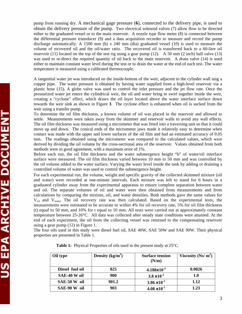
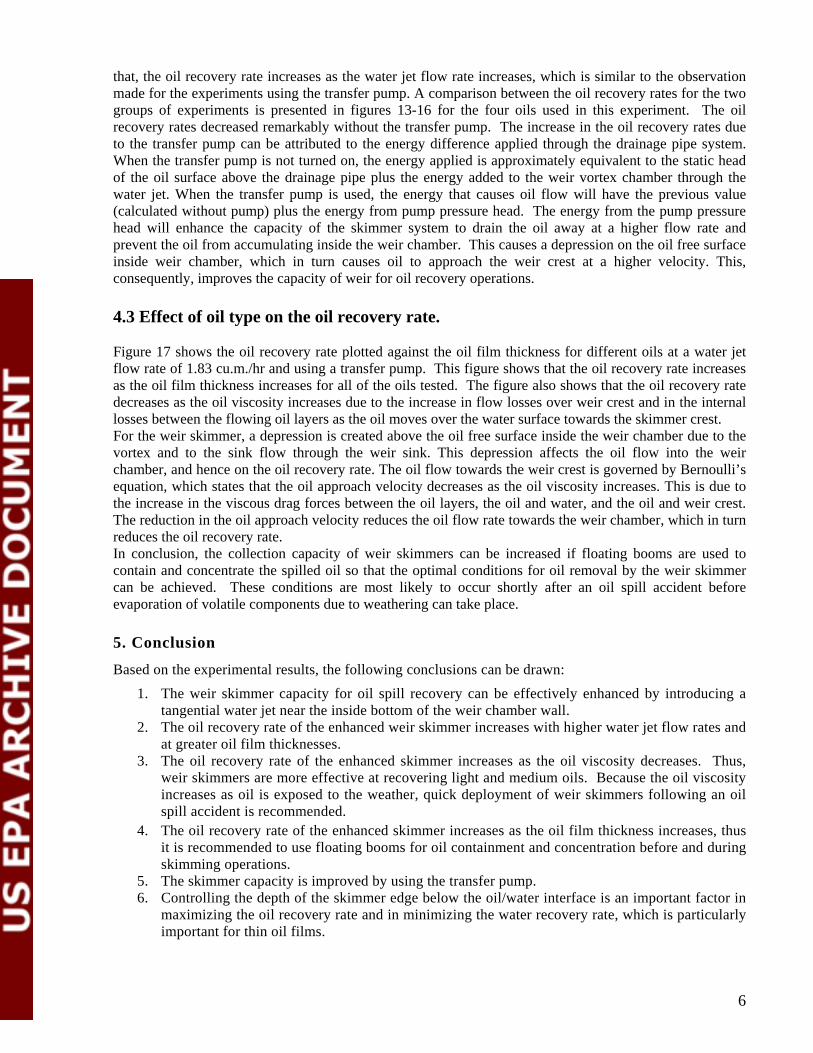
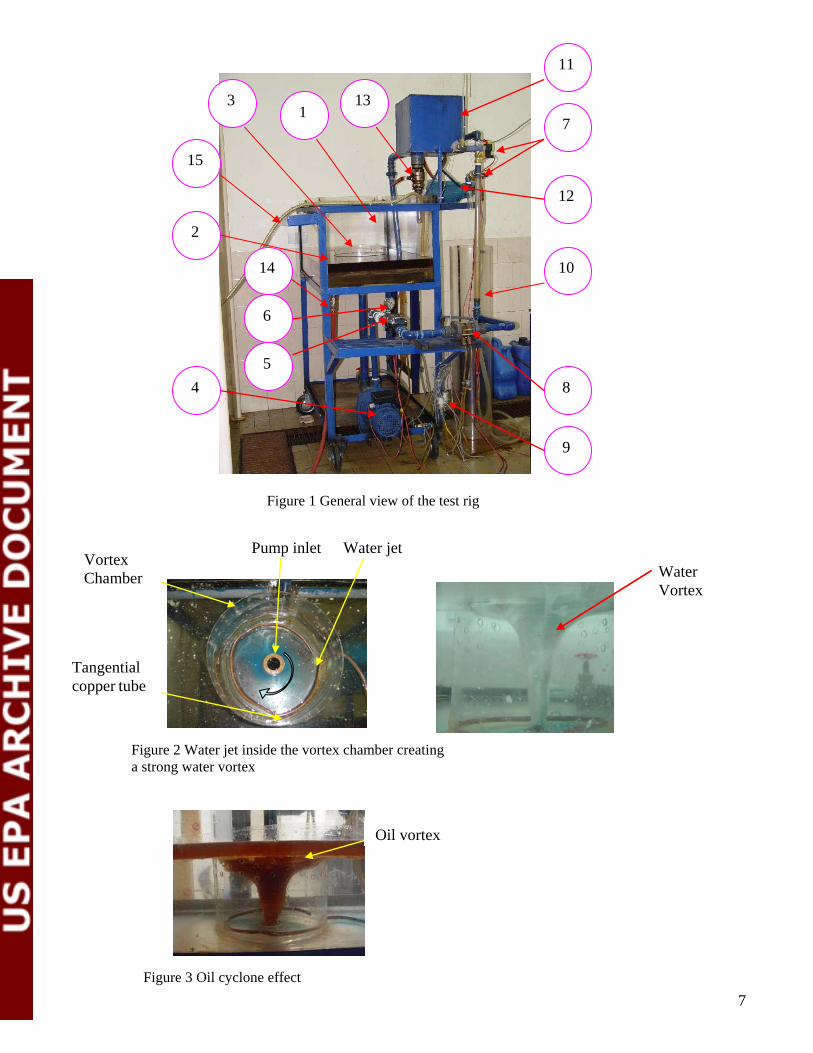
A tangential water jet was introduced on the inside-bottom of the weir, adjacent to the cylinder wall sing a copper pipe. The water pressure is obtained by having water supplied from a high-level reservoir via a plastic hose (15). A globe valve was used to control the inlet pressure and the jet flow rate. Once the pressurized water jet enters the cylindrical weir, the oil and water bring to swirl together inside the weir, creating a "cyclone" effect, which draws the oil layer located above the water interface surface down towards the weir sink as shown in Figure 3. The cyclone effect is enhanced when oil is sucked from the weir using a transfer pump. To determine the oil film thickness, a known volume of oil was placed in the reservoir and allowed to settle. Measurements were taken away from the skimmer and reservoir walls to avoid any wall effects. The oil film thickness was measured using a micrometer that was fitted into a traversing unit so that it could move up and down. The conical ends of the micrometer jaws made it relatively easy to determine when contact was made with the upper and lower surfaces of the oil film and had an estimated accuracy of 0.05 mm. The readings obtained using the micrometer was compared to the calculated values, which were derived by dividing the oil volume by the cross-sectional area of the reservoir. Values obtained from both methods were in good agreement, with a maximum error of 1%. Before each run, the oil film thickness and the water submergence height “h” of water/oil interface surface were measured. The oil film thickness varied between 10 mm to 50 mm and was controlled by the oil volume added to the water surface. Varying the water level inside the tank by adding or draining a controlled volume of water was used to control the submergence height. For each experimental run, the volume, weight and specific gravity of the collected skimmed mixture (oil and water) were recorded at one-minute intervals. Each mixture was left to stand for 6 hours in a graduated cylinder away from the experimental apparatus to ensure complete separation between water and oil. The separate volumes of oil and water were then obtained from measurements and from calculations by comparing the mixture, oil, and water densities. Both methods gave the same values for Voil and Vwater. The oil recovery rate was then calculated. Based on the experimental tests, the measurements were estimated to be accurate to within 4% for oil recovery rate, 5% for oil film thickness (t) equal to 50 mm, and 10% for t equal to 10 mm. All tests were carried out at approximately constant temperature between 25-26°C. All data was collected after steady state conditions were attained. At the end of each experiment, the oil from the collecting vessel was returned to the compensating reservoir using a gear pump (12) in Figure 1. The four oils used in this study were diesel fuel oil, SAE 40W, SAE 50W and SAE 90W. Their physical properties are presented in Table 1.
Table 1: Physical Properties of oils used in the present study at 25°C.
Oil type Density (kg/m3) Surface tension (N/m)
Viscosity (Ns/ m2)
Diesel fuel oil 825 4.188x10⁻² 0.0026 SAE-40 W oil 900 3.8 x10⁻² 1.0 SAE-50 W oil 901.2 3.86 x10⁻² 1.12 SAE-90 W oil 903 4.08 x10⁻² 1.23
3
3. Test procedure
Two groups of experiments were performed during this investigation: the first group was carried out while the pump was operating and the second group was performed while the pump was shut off. The following test procedure was followed:
1. The water reservoir was filled 100 mm past the cylindrical weir upper edge. 2. At the beginning of each run, air was vented from the piping systems. 3. Oil was added above the water surface until the desired value of oil thickness was attained. 4. The pressurized water line was opened gradually until the water jet generated inside the weir was
able to circulate the water. The pump was started at the same time the water line was opened (first group of experiments)
5. Observations were made for a period of 30 to 60 seconds to determine if the oil vortex developed.
6. After a strong, stable oil vortex is formed, the electrical valve was turned on, and oil/water mixture was directed to the graduated vessel. At the same time, the measurements from the pressure transducers and the thermocouple were recorded.
7. Because the water level in the tank will increase from the continuous inflow of water from the jet, the drain valve was opened and adjusted to maintain a constant water level.
8. Using a manually controlled valve (13), oil from the compensating tank (11) was added to the water reservoir surface to maintain a constant oil film thickness throughout the experimental run.
9. The above procedure was repeated for different water levels and for different water jet flow rates from 0.77 up to 1.8 Cu.m/hr.
10. The pump was stopped after the corresponding inlet water jet flow rate and the oil recovery rate were recorded for each water submergence height.
11. The same procedure was repeated for gravity free flow tests (second group of experiments). 12. The above procedure was repeated for different type of oils.
4. Tests, results and discussion
4.1 Observations
Before discussing the experimental results, it is important to note that, once a strong vortex is formed, the cyclone effect often persists for a long time period, sometimes longer than one hour. In other words, the skimmer achieved a steady state oil recovery rate over a long time period, which provides confidence in the device’s effectiveness.
Prior observations suggest that, in the absence of a tangential water jet, the single-phase flow field (i.e., water only) inside the skimmer chamber is similar to the classical flow field that develops when water drains from a small hole located at a container’s bottom. The strong, localized deformation at the water surface makes the generated vortex highly visible. Inside the vortex core, the axial velocity is high, which is essential for a strong swirl. The flow structure, the free surface shape, and the interdependence of important characteristics such as the central depression size and the overflow rate are dependent both on the rotational speed (circulation strength) of the vortex core and the liquid depth inside the skimmer. A high tangential velocity near the center is a unique feature of any vortex, which if strong enough can entrap a lower density fluid (i.e., air) near its base.
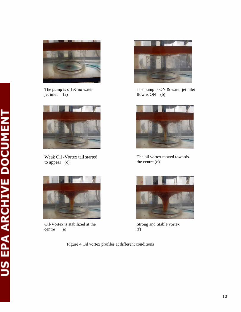
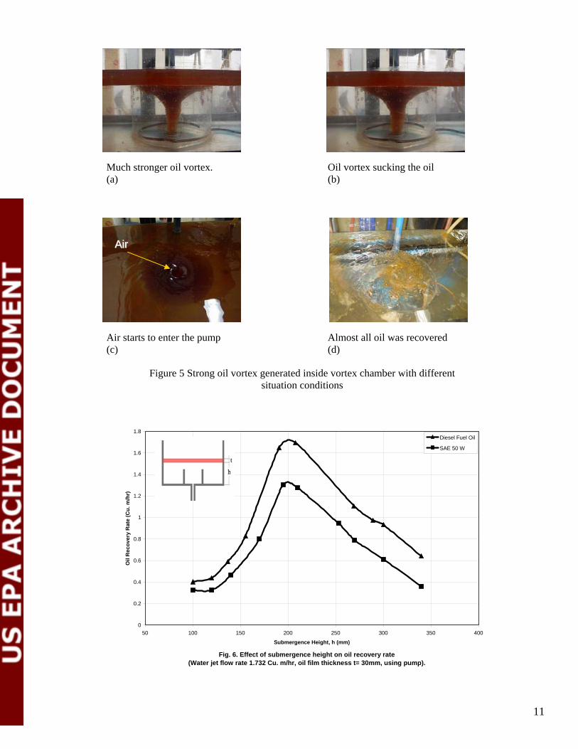
Figures 4a to 4f show observations that were recorded by a digital video camera. The figures show the water circulation inside the vortex chamber after the introduction of the water jet. After the pump was turned on, a weak oil vortex started to form with its characteristically thin tail moving towards the chamber drain hole. Seconds later, the oil vortex stabilizes but continues to gain strength at the centre of the chamber near the drain hole. However, a thick vortex tail (figure 4d) extending downward coincided with the vortex’s gain in strength. Meanwhile, the oil was pumped to the collection tank. After that, the oil film thickness was diminished. The pump as shown in figure 5c recovered most of the oil. But when the oil film was less than 10 mm thick, an air-oil vortex started to appear. At this moment the test was stopped.
4

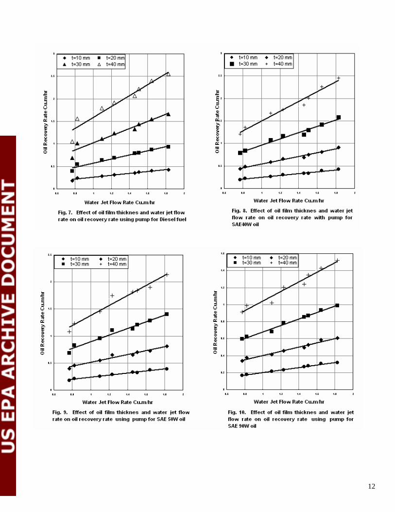
The preliminary observation shown in video film for flowing (of either oil only or oil-water mixture) slick approaching the weir indicated that the slick film thickness drops as at approaches the weir. This drop in slick film thickness occurs due to the existence of weir itself. This drop is dependent on slick type (single or two phase), viscosity, skimming flow rate, weir edge conditions. Figure 6 presents the effect of submergence height “h” on the oil recovery rate for diesel fuel oil and SAE 50W oil at 30 mm film thickness. The measurements were taken when the oil vortex was created at a constant jet flow rate of 1.732 Cu.m/hr. The results indicate that, the oil recovery rate first increases as the submergence height increases until an optimum value of about 200 mm (cylindrical chamber height) is reached. When the submergence height is less than the chamber height, oil and water must enter the skimmer chamber through the holes on the chamber circumference, which restricts the flow of both liquids, especially the oil which has a higher viscosity than water. When this occurs, flow to drain hole is provided mainly by the water layer at the bottom of the chamber. As the submergence height increases, the effective head increases which results in increased flow of both liquids through the chamber holes, and an increase in the oil recovery rate. When the submergence height reaches a value equal to or greater than 170 mm, oil enters the chamber over the upper edge, which leads to a heighten oil recovery rate. Only oil can enter the chamber since water flow to the chamber is diminished because of the holes in the chamber wall. The maximum oil recovery rate was attained when the oil/water interface surface was just above the chamber’s upper edge. This allowed a thin film of water to pass over the chamber edge and lubricate the oil flow, which reduced the viscous effects on the weir crest and allowed more oil to flow into the weir chamber. More water enters the chamber as the submergence height continues to increase, which dilutes the amount of oil passing through the drain hole and consequently the oil recovery rate decreases. Moreover, figure 6 shows similar behavior when SAE 50W oil at 30 mm film thickness and with the inlet tangential jet at the same flow rate was tested. With both oils, the maximum recovery rate was attained at a submergence height of 200 mm, which is the same height of the weir chamber. The oil recovery rate decreased when the submergence height was above or below 200 mm. The negative effect (i.e. decreasing of oil recovery rate) at a high submergence height is attributed to the reduced ability of the oil vortex to recover the spilled oil. It is important to point out that, all the following tests were undertaken at an optimum submergence height (h = 200 mm). Figure 7 shows the oil recovery rate against the tangential water flow rate for diesel fuel oil at film thicknesses between 10 to 40 mm. These tests were undertaken with the aid of the transfer pump. The tangential water jet flow rate varied from 0.72 to 1.8 cu.m/hr. The results indicated that, as the water jet flow rate increased, the oil recovery rate increased due to higher water jet momentum. Higher water jet momentum increases circulation strength, and hence the strength of the oil-removing vortex generated inside the weir chamber. The strong vortex generated inside the chamber separates oil from water. When a water jet is introduced into the weir chamber at a high velocity, the momentum it imparts on the two-fluid mass increases the circulation in the surrounding fluid, eventually forming a vortex. The jet gives rise to combined, Rankine-type vortex conditions with a forced vortex forming near the drain hole and a free vortex forming in the outer region toward the periphery. As a result, oil builds up inside the vortex core and is collected at a rate proportional to the vortex strength. This resulted in secondary flow that causes the fluid layers chamber floor (water) to move toward the outlet drain hole at the chamber bottom center. The oil reaches the vortex core in the shape of a thick-tail funnel, which can be continuously flushed out through the drain hole. This effect is enhanced at higher water jet flow rates. Figure 7 also shows that the oil recovery rate increased as the film thickness increased due to the increase in head causing flow over the weir crest.
The results presented in figures 8 through 10 for other types of oil (SAE 40W, SAE 50W and SAE90 W oil), showed the same trend in all cases. The oil recovery rate increased as the tangential water jet flow rate and oil film thickness increased.
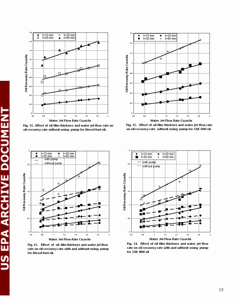
4.2 Effect of the absence of transfer pump on the oil recovery rate The second group of experiments was conducted without the use of the transfer pump. Regardless, a strong, stable vortex was created after the drain valve that was fitted to an outlet pipe located 1.25 m below the weir sink was opened. Individual tests were carried out for oil film thicknesses between 10 to 40 mm and water jet flow rates between 0.72 and 1.8 cu.m/hr. The results presented in figures 11 and 12 indicate
5
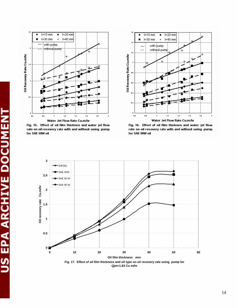
that, the oil recovery rate increases as the water jet flow rate increases, which is similar to the observation made for the experiments using the transfer pump. A comparison between the oil recovery rates for the two groups of experiments is presented in figures 13-16 for the four oils used in this experiment. The oil recovery rates decreased remarkably without the transfer pump. The increase in the oil recovery rates due to the transfer pump can be attributed to the energy difference applied through the drainage pipe system. When the transfer pump is not turned on, the energy applied is approximately equivalent to the static head of the oil surface above the drainage pipe plus the energy added to the weir vortex chamber through the water jet. When the transfer pump is used, the energy that causes oil flow will have the previous value (calculated without pump) plus the energy from pump pressure head. The energy from the pump pressure head will enhance the capacity of the skimmer system to drain the oil away at a higher flow rate and prevent the oil from accumulating inside the weir chamber. This causes a depression on the oil free surface inside weir chamber, which in turn causes oil to approach the weir crest at a higher velocity. This, consequently, improves the capacity of weir for oil recovery operations.
4.3 Effect of oil type on the oil recovery rate.
Figure 17 shows the oil recovery rate plotted against the oil film thickness for different oils at a water jet flow rate of 1.83 cu.m./hr and using a transfer pump. This figure shows that the oil recovery rate increases as the oil film thickness increases for all of the oils tested. The figure also shows that the oil recovery rate decreases as the oil viscosity increases due to the increase in flow losses over weir crest and in the internal losses between the flowing oil layers as the oil moves over the water surface towards the skimmer crest. For the weir skimmer, a depression is created above the oil free surface inside the weir chamber due to the vortex and to the sink flow through the weir sink. This depression affects the oil flow into the weir chamber, and hence on the oil recovery rate. The oil flow towards the weir crest is governed by Bernoulli’s equation, which states that the oil approach velocity decreases as the oil viscosity increases. This is due to the increase in the viscous drag forces between the oil layers, the oil and water, and the oil and weir crest. The reduction in the oil approach velocity reduces the oil flow rate towards the weir chamber, which in turn reduces the oil recovery rate. In conclusion, the collection capacity of weir skimmers can be increased if floating booms are used to contain and concentrate the spilled oil so that the optimal conditions for oil removal by the weir skimmer can be achieved. These conditions are most likely to occur shortly after an oil spill accident before evaporation of volatile components due to weathering can take place.
5. Conclusion
Based on the experimental results, the following conclusions can be drawn: 1. The weir skimmer capacity for oil spill recovery can be effectively enhanced by introducing a
tangential water jet near the inside bottom of the weir chamber wall. 2. The oil recovery rate of the enhanced weir skimmer increases with higher water jet flow rates and
at greater oil film thicknesses. 3. The oil recovery rate of the enhanced skimmer increases as the oil viscosity decreases. Thus,
weir skimmers are more effective at recovering light and medium oils. Because the oil viscosity increases as oil is exposed to the weather, quick deployment of weir skimmers following an oil spill accident is recommended.
4. The oil recovery rate of the enhanced skimmer increases as the oil film thickness increases, thus it is recommended to use floating booms for oil containment and concentration before and during skimming operations.
5. The skimmer capacity is improved by using the transfer pump. 6. Controlling the depth of the skimmer edge below the oil/water interface is an important factor in
maximizing the oil recovery rate and in minimizing the water recovery rate, which is particularly important for thin oil films.
6
4
7
12
10
5 8
1
15
2
6
9
11
133
14
Figure 1 General view of the test rig
Vortex
Vortex Water
Pump inlet
Tangential copper tube
Water jet
Chamber
Figure 2 Water jet inside the vortex chamber creating a strong water vortex
Oil vortex
Figure 3 Oil cyclone effect 7
Acknowledgement
The author is grateful to “The National Council for Scientific Research”, Beirut, Lebanon for the financial support of this research project.
Future plans
The present study shows a considerable improvement in the oil recovery rate of sharp edged weir skimmer under laboratory conditions (No effect of water movement as encountered on the seas). Future studies are needed to determine the effect of waves and currents on the oil collection capacity of this type of skimmers. Also the effect of water jet on the performance of weir skimmer with rounded entrances similar to those used in real oil spill recovery systems should be considered in future studies. The effects of chamber height to diameter on oil recovery rates could also be investigated.
References
Abdelnour, R. and Purves, W., 1978. The performance of weir skimmer., Arctic Canada Ltd. May, Report submitted to Environmental Protection Service, Environment Canada. Abdelnour, R., Purves, W., and Wallace, W.G., 1978. A field evaluation of eight small stationaryskimmers. Technical Development Report EPS 4-EC-78-5, Environmental Protection Service,Environment Canada Abdelnour, R., Roberts, B., and Purves, W., 1980. A field evaluation of oil skimmers., Proceedings of the Third Arctic Marine Oil Spill Conference, Edmonton, Alberta, Canada. Borst, M. and Griffiths, R.A., 1984. OHMSETT Test Series 77. EPA-600/2-04-074. Claus,G.F. and Kuhnlein, W.L., 1991. Efficiency of selected oil skimming systems in irregular seas, Oil Spill Conference, 115-124. Deligne, G.A.L., 1989. Barrier failure by critical accumulation of viscous oil, Oil Spill Conference:143-148.Hammoud, A.H. and Khalil, M.F., 2000a. Hydrodynamic Performance of the Belt skimmer forRemoving Oils Proceedings of the Second International Conference on Oil Spill in theMediterranean and Black Sea Regions, Istanbul-Turkey 31st October – 3rd November, pp. 125-135. Hammoud, A.H. and Khalil, M.F., 2000b. Effect of Disk Material on Disk Skimmer Performance. Proceedings of the Second International Conference on Oil Spill in the Mediterranean and Black Sea Regions, Istanbul -Turkey 31st October – 3rd November, pp. 153-164. Hammoud, A.H. and Khalil, M.F., 2000c. Performance of Rotating Drum Skimmer in Oil SpillRecovery" Proceedings of the Institution of Mechanical Engineers, Part E: Journal of ProcessMechanical Engineering. Vol. 217, No E1, pp. 49-57. Hammoud, A.H., Assaf, W.C., and Khalil, M.F., 2003. Performance of Rotating Coarse BrushSkimmer in Oil Spill Recovery, Proceedings of Third International Conference on Oil Spills, OilPollution and Remediation, 16-18 September 2003, Istanbul, Turkey, pp.139-153. Jensen, H., McClimans, T.A., and Johannessen, B.O., 1995a. Evaluation of weir skimmers for oil recovery-factors, procedure and example, (in Norwegian), SINTEF NHL Report No. STF60 A95003. Jensen, H., McClimans, T.A., and Johannessen, B.O., 1995b. Evaluation of weir skimmers without testing, Eighteenth AMOP Technical Seminar Proceedings, Edmonton, Alberta, Canada, pp.689-704.Khalil, M.F., and Hammoud, A.H., 2000. Influence of Design and Operation Parameter on Disc Skimmer Performance Proceedings of the Second International Conference on Oil Spill in the Mediterranean and Black Sea Regions, Istanbul-Turkey 31st October– 3rd November, pp.137-152.
8
Leibovich, S., 1977, Hydrodynamic problems in oil-spill control and removal, Journal of PetroleumTechnology, March:3 11-324. Lorenzo, T., Therrien, R., and Johannessen, B.O., 1995. Study of viscosity and emulsion effects on skimmer performance., Eighteenth AMOP Technical Seminar Proceedings, Edmonton,Alberta,Canada., pp.705-729. McCracken, W.E., 1977. Performance testing of selected inland oil spill control equipment. EPA-600/2-77-150.McCracken, W.E. and Schwartz, S.H., 1977. Performance testing of spill control devices on floatablehazardous materials. EPA-600/2-77-222. Rao, N.S.L., 1975. Theory of weirs, Advances in Hydro sciences 10:309-400. Ed. V.T. Chow, Academic Press. Schulze, R., 1993. Ch. 2. Oil spill skimmers, World catalog of oil spill response products, FourthEdition, Robert Schulze Environmental Consultant, Inc.Schulze, R., 1998. Oil Spill Response: Performance review skimmers. American Society for Testing and Materials : Manual Series : MNL34. Smith, J.B.H., McLellan, C., and Pintler, L.R., 1987. Development of an oil skimming system tomeet Navy specifications., Oil Spill Conference:91-94. Solesberg, L., Wallace, W.G., and Dunne, M., 1977. Field evaluation of oil spill recovery devices: Phase two. Technical Development Report EPS 4-77-14, Environmental Protection Service, Environment Canada. Topham, D.R., 2002. An analysis of the performance of weir type oil skimmers, Spill Science and Technology Bulletin, Vol.7, 289-297. Tscocalis, E.T., Kpwenhoven, W., and Perkis, A.N., 1994. A survey of classical and new response methods for marine oil spill cleanup, Marine Technology, Vol.3 1, pp. 79-93. Turner, J.T., Beech, H., and Christodoulou, M.S., Development of an Improved form of RotatingDisc Skimmer , The Dock and Harbor Authority, 1987, Vol 68,No. 790,pp.5-10
Turner, J.T., Milligan, D., Hobkinson, S.L.and Macbeth, N.I., Waste Minimization in Refineries using the Kebab T-Disc™ Skimmer, presented at the International Middle East Petrotech Conference, Bahrain. 1996
Turner, J.T. ,Mac beth, N.I., and Speight, R.J., Oil Recovery from Refinery Waste using the T-Disc Skimmer , Proceedings of the First Conference on oil Spills in the Mediterranean and Black SeaRegions , Istanbul – Turkey 15th –18th September 1998, PP 311-323. Turner,J.T., and Najar. A.M. Enhanced oil recovery using the rotating-disc skimmer , Proceedings of the institution of Mechanical Engineers, Part E: journal of process Mechanical Engineering,v214,4,2000,pp 271-282.Wilson, H.B., 1981. Development and testing of a weir boom for oil recovery at sea, Oil Spill Conference, pp.643-648. Wanga, S.D., Shena, Y.M., and Zhengb, Y.H., 2005. Two-dimensional numerical simulation for and fate of oil spills in seas, Ocean Engineering (32) 1556–1571.
9
TThhee ppuummpp iiss off && nnoo wwaatteerr The pump is ON & water jet inlet jjeett iinnlleett ((aa)) flow is ON (b)
Weak Oil -Vortex tail started The oil vortex moved towards to appear (c) the centre (d)
Oil-Vortex is stabilized at the Strong and Stable vortex centre (e) (f)
Figure 4 Oil vortex profiles at different conditions
10
Much stronger oil vortex. Oil vortex sucking the oil (a) (b)
AAiirr
Air starts to enter the pump Almost all oil was recovered (c) (d)
Figure 5 Strong oil vortex generated inside vortex chamber with different situation conditions
Fig. 6. Effect of submergence height on oil recovery rate (Water jet flow rate 1.732 Cu. m/hr, oil film thickness t= 30mm, using pump).
0
0.2
0.4
0.6
0.8
1
1.2
1.4
1.6
1.8
50 100 150 200 250 300 350 400
Submergence Height, h (mm)
Oil
Rec
over
y R
ate
(Cu.
m/h
r)
Diesel Fuel Oil
SAE 50 W
11
12
13
0
1
2
3
0.5
1.5
2.5
Oil
reco
very
rate
C
u.m
/hr
DIESEL
SAE 40W
SAE 50 W
SAE 90 W
10 20 30 40 50 60 Oil film thickness mm
Fig. 17. Effect of oil film thickness and oil type on oil recovery rate using pump for Qjet=1.83 Cu m/hr
14
0