Embed Size (px)
Citation preview

LG ROOM AIR CONDITIONEROWNER'S MANUAL
ACONDICIONADOR DE AIRE DE VENTANAMANUAL DEL PROPIETARIO
LG
website http://www.lgappliances.com
Please read the operating instructions and safety precautions carefullyand thoroughly before installing and operating your room air conditioner.
Por favor lea las instrucciones de operación y las precauciones deseguridad cuidadosa y totalmente antes de instalar y operar suacondicionador de aire de ventana.
MODELS, MODELOS:
IMPORTANTPlease read through this manual. It contains valuableinformation about your air conditioner.This manual mayhelp save time and money by explaining proper airconditioner maintenance and preventing improper use.
PRECAUTIONSPay close attention to precautions in order to preventpotential hazards and damage from misuse or improperinstallation. LG is not responsible for any damagescaused by misuse of the air conditioner.
ENG
LISHESPA
ÑO
L
ENERGY STAR(LT103CER)
LT1430CRLT103CERLT123CNRLT143CNR

2 Room Air Conditioner
Window-Type Air Conditioner Owner’s Manual
TABLE OF CONTENTS
FOR YOUR RECORDSWrite the model and serial numbers here:
Model #
Serial #
You can find them on a label on the side of each unit.
Dealer's Name
Date Purchased
� Staple your receipt to this page in the event you need itto prove date of purchase or for warranty issues.
READ THIS MANUALInside you will find many helpful hints on how to use andmaintain your air conditioner properly. Just a little preventivecare on your part can save you a great deal of time andmoney over the life of your air conditioner.
You'll find many answers to common problems in the chartof troubleshooting tips. If you review our chart of
Troubleshooting Tips first, you may not need to call forservice at all.
PRECAUTION• Contact the authorized service technician for repair
or maintenance of this unit.
• Contact the installer for installation of this unit.
• The air conditioner is not intended for use by youngchildren or invalids without supervision.
• Young children should be supervised to ensure thatthey do not play with the air conditioner.
• When the power cord is to be replaced, replacementwork shall be performed by authorized personnel onlyusing only genuine replacement parts.
• Installation work must be performed in accordancewith the National Electric Code by qualified andauthorized personnel only.
Safety Precautions ..........................3
Before Operation .............................7
Introduction ....................................8
Electrical Safety ..............................9
Installation ....................................11
Operating Instructions .................18
Maintenance and Service ............21

Owner’s Manual 3
ENG
LISHSafety Precautions
Safety PrecautionsTo prevent injury to the user or other people and property damage, the following instructionsmust be followed.� Incorrect operation due to ignoring instruction will cause harm or damage. The seriousness
is classified by the following indications.
� Meanings of symbols used in this manual are as shown below.
WARNING
CAUTION
This symbol indicates the possibility of death or serious injury.
This symbol indicates the possibility of injury or damage to properties only.
WARNING� Installation
Be sure not to do.
Be sure to follow the instruction.
Don’t use a power cord, aplug or a loose socket whichis damaged.
• Otherwise, it may cause a fireor electrical shock.
Always plug into a groundedoutlet.
• Otherwise, it may cause a fireor electrical shock.
Do not modify or extend thepower cord length.
• It will cause electric shock or firedue to heat generation.
Do not disassemble ormodify products.
• It may cause failure andelectric shock.
Be caution when unpackingand installing.
• Sharp edges may causeinjury.
Do not use the power cord nearflammable gas or combustiblessuch as gasoline, benzene,thinner, etc.
• It may cause explosion or fire.
Gasolin

4 Room Air Conditioner
Safety Precautions
� Operation
Do not place the power cordnear a heater.
• It may cause fire and electricshock.
Do not allow water to runinto electric parts.
• It will cause failure of machine orelectric shock.
Use a soft cloth to clean. Donot use wax, thinner, or astrong detergent.
• The appearance of the airconditioner may deteriorate,change color, or develop surfaceflaws.
Wax Thinner
Ventilate the room well whenusing this appliancetogether with a stove, etc.
• An oxygen shortage may occur.
Turn off the power andbreaker firstly whencleansing the unit.
• Since the fan rotates at highspeed during operation, it maycause injury.
Turn off the main powerswitch when not using it fora long time.
• Prevent accidental startup andthe possibility of injury.
Unplug the unit if strangesounds, odors, or smokecome from it.
• Otherwise it may cause fire andelectric shock accident.
Do not open the suctioninlet grill of the productduring operation.
• Otherwise, it may electricalshock and failure.
If water enters the product, turnoff the the power switch of themain body of appliance. Contactservice center after taking thepower-plug out from the socket.
Do not place heavy objecton the power cord and takecare so that the cord shouldnot be pressed.
• There is danger of fire or electricshock.
Do not share the outlet withother appliances.
• It will cause electric shock or firedue to heat generation.
Take the power plug out ifnecessary, holding the headof the plug and do not touchit with wet hands.
• Otherwise, it may cause a fireor electrical shock.

Owner’s Manual 5
ENG
LISHSafety Precautions
CAUTION
� Installation
Do not operate or stop theunit by inserting or pullingout the power plug.
• It will cause electric shock or firedue to heat generation.
Do not damage or use anunspecified power cord.
• It will cause electric shock or fire.
Do not operate with wethands or in dampenvironment.
• It will cause electric shock.
Hold the plug by the headwhen taking it out.
• It may cause electric shock anddamage.
When gas leaks, open thewindow for ventilationbefore operating the unit.
• Otherwise, it may causeexplosion, and a fire.
Never touch the metal partsof the unit when removingthe filter.
• They are sharp and may causeinjury.
Install the product so that the noise or hotwind from the outdoor unit may not causeany damage to the neighbors.
• Otherwise, it may cause dispute with theneighbors.
Keep level parallel in installing the product.
• Otherwise, it may cause vibration or waterleakage.

6 Room Air Conditioner
Safety Precautions
� Operation
Be cautious not to touch thesharp edges wheninstalling.
• It may cause injury.
Avoid excessive cooling andperform ventilationsometimes.
• Otherwise, it may do harm toyour health.
Do not insert the hands orbars through the air inlet oroutlet during operation.
• Otherwise, it may causepersonal injury.
Do not put a pet or houseplant where it will beexposed to direct air flow.
• It may cause injury.
Do not block the inlet oroutlet of air flow.
• It may cause product failure.
Use a soft cloth to clean. Donot use wax, thinner, or astrong detergent.
• The appearance of the airconditioner may deteriorate,change color, or develop surfaceflaws.
Do not step on theindoor/outdoor unit and donot put anything on it.
• It may cause an injury throughdropping of the unit or fallingdown.
Always insert the filtersecurely.Clean it every two weeks.
• Operation without filters willcause failure.
Do not drink water drainedfrom air conditioner.
• It contains containments and willmake you sick.

Before Operation
Owner’s Manual 7
ENG
LISH
Before Operation
1. Contact an installation specialist for installation.2. Plug in the power plug properly.3. Use a dedicated circuit.4. Do not use an extension cord.5. Do not start/stop operation by plugging/unplugging the power cord.6. If the cord/plug is damaged, replace it with only an authorized replacement
part.
1. Being exposed to direct airflow for an extended period of time could behazardous to your health. Do not expose occupants, pets, or plants to directairflow for extended periods of time.
2. Due to the possibility of oxygen deficiency, ventilate the room when usedtogether with stoves or other heating devices.
3. Do not use this air conditioner for non-specified special purposes (e.g.preserving precision devices, food, pets, plants, and art objects). Such usagecould damage the items.
1. Do not touch the metal parts of the unit when removing the filter. Injuries canoccur when handling sharp metal edges.
2. Do not use water to clean inside the air conditioner. Exposure to water candestroy the insulation, leading to possible electric shock.
3. When cleaning the unit, first make sure that the power and breaker are turnedoff. The fan rotates at a very high speed during operation. There is apossibility of injury if the unit’s power is accidentally triggered on whilecleaning inner parts of the unit.
For repair and maintenance, contact your authorized service dealer.
Preparing for Operation
Usage
Cleaning and Maintenance
Service

8 Room Air Conditioner
Introduction
This symbol alerts you to the risk of electric shock.
This symbol alerts you to hazards that could cause harm tothe air conditioner.
This symbol indicates special notes.NOTICE
This appliance should be installed in accordance with the National Electric Code.
IntroductionSymbols Used in this Manual
Features
CABINET
FRONT GRILLE
INLET GRILLE(Air Intake)
AIR FILTER
HORIZONTAL AIR DEFLECTOR(Vertical Louver)
VENT CONTROL
VERTICAL AIR DEFLECTOR(Horizontal Louver)
AIR DISCHARGE
SLEEVE ASSEMBLY(Including Aluminum Rear grille)
THE SLEEVE AND THE REAR GRILLE(optionally supplied with your unit)
THE UNIT
REAR GRILLE(Aluminum Rear grille)

Electrical Safety
Owner’s Manual 9
ENG
LISH
Electrical SafetyElectrical Data
115V~ 230V~ Power cord may include a current interrupter device. A test and reset button is provided on the plug case. The device should be tested on a periodic basis by first pressing the TEST button and then the RESET button. If the TEST button does not trip or if the RESET button will not stay engaged, discontinue use of the air conditioner and contact a qualified service technician.
Use Wall Receptacle Power Supply
Standard 125V, 3-wire groundingreceptacle rated 15A, 125V AC
Standard 250V, 3-wire groundingreceptacle rated 15A, 250V AC
Use 15 AMP. timedelay fuse or 15 AMP.circuit breaker.
Use 20 AMP. timedelay fuse or 20 AMP.circuit breaker.
Standard 250V, 3-wire groundingreceptacle rated 20A, 250V AC
Never push the test button duringoperationOtherwise this plug can damaged.This device contains chemical, includinglead, known to the State of California tocause cancer, and birth defects or otherreproductive harm.Wash hands after handling.Do not remove, modify or immerse this plug.If this device trips, the cause it to becorrected before further use.
The conductors inside this cord aresurrounded by shields, which monitorleakage current.These shields are not grounded.
Periodically examine the cord for anydamage. Do not use this product in theevent the shields become exposed.Avoid shock hazard, this unit can notbe user serviced opening the tamperresistant. Sealed portion of the unitvoids all warranties and performanceclaims. This unit not intended for useas an on-off switch.
The shape may be different according to its model.
NOTICE
DO NOT USE AN EXTENSION CORD on 230,208, and 230/208 Volt units.All wiring should be made in accordance with localelectrical codes and regulations.Aluminum house wiring may pose specialproblems. Consult a qualified electrician.
NOTICE

10 Room Air Conditioner
Electrical Safety
IMPORTANT(PLEASE READ CAREFULLY)FOR THE USER'S PERSONAL SAFETY, THISAPPLIANCE MUST BE PROPERLY GROUNDED
The power cord of this appliance is equipped with athree-prong (grounding) plug. Use this with a standardthree-slot (grounding) wall power outlet to minimize thehazard of electric shock. The customer should havethe wall receptacle and circuit checked by a qualifiedelectrician to make sure the receptacle is properlygrounded.
DO NOT CUT OR REMOVE THE THIRD (GROUND)PRONG FROM THE POWER PLUG.
A. SITUATIONS WHEN THE APPLIANCE WILL BEDISCONNECTED OCCASIONALLY:
Because of potential safety hazards, we stronglydiscourage the use of an adapter plug. However, if youwish to use an adapter, a TEMPORARYCONNECTION may be made. Use UL-listed adapter,available from most local hardware stores.The large slot in the adapter must be aligned with thelarge slot in the receptacle to assure a proper polarityconnection.
: Attaching the adapter ground terminal to the wallreceptacle cover screw does not ground theappliance unless the cover screw is metal, and notinsulated, and the wall receptacle is groundedthrough the house wiring. The customer shouldhave the circuit checked by a qualified electrician tomake sure the receptacle is properly grounded.
Disconnect the power cord from the adapter, usingone hand on each. Otherwise, the adapter groundterminal might break. DO NOT USE the appliance witha broken adapter plug.
B. SITUATIONS WHEN THE APPLIANCE WILL BEDISCONNECTED OFTEN.
Do not use an adapter plug in these situations.Unplugging the power cord frequently can lead to aneventual breakage of the ground terminal. The wallpower outlet should be replaced by a three-slot(grounding) outlet instead.
USE OF EXTENSION CORDS
Because of potential safety hazards, we stronglydiscourage the use of an extension cord. However, ifyou wish to use an extension cord, use a CSAcertified/UL-listed 3-wire (grounding) extension cord,rated at 15A, 250V.
Electrical Safety

Owner’s Manual 11
ENG
LISHInstallation
InstallationRemove packing materials from the wall sleeve and tapefrom the air conditioner.
INSTALLATION REQUIREMENTSIf you use an existing wall sleeve, you shouldmeasure its dimensions.Install the new air conditioner according to theseinstallation instructions to achieve the bestperformance. All wall sleeves used to mount the newair conditioner must be in good structural conditionand have a rear grille to securely attach the new airconditioner. (FIG. 1)With the LGE sleeve(optionally supplied withyour unit), you can maintain the best performance ofthe new air conditioner. (FIG. 2)
ELECTRICAL SERVICECheck your available electrical service. The powersupply available must be the same as that shown onthe unit nameplate (found on left side of cabinet).
All models are equipped with a 3-prong service plugto provide proper service and safe positivegrounding. Do not change plug in any way. Do notuse an adapter plug. If your present wall outlet doesnot match your plug, call a qualified electrician tomake the necessary corrections. SAVE CARTON forstorage and this OWNER'S MANUAL for futurereference. The carton is the best way to store unitduring winter or when not in use.
INSTALLATION HARDWARE
14-13/32"(366 mm)
24"(610 mm)
18-15/32"(468 mm)
20-3/32"(511 mm)
15
6
7
8
3
2 4
9
2 Size options
2 Size options
To avoid risk of personal injury, propertydamage, or product damage due to the weight ofthis device and sharp edges that may beexposed:• Air conditioners covered in this manual pose an
excessive weight hazard. Two or more people areneeded to move and install the unit.To prevent injury or strain, use proper lifting andcarrying techniques when moving unit.
• Carefully inspect location where air conditioner willbe installed. Be sure it will support the weight ofthe unit over an extended period of time.
• Handle air conditioner with care. Wear protectivegloves whenever lifting or carrying the unit. AVOIDthe sharp metal fins of front and rear coils.
• Make sure air conditioner does not fall duringinstallation.
REQUIRED TOOLS:
• Tight Fitting gloves• Standard screwdriver• Phillips screwdriver• Pliers• Sharp knife
• 3/8-inch open endwrench or adjustablewrench
• 1/4-inch hex socketand ratchet
• Tape measure• Electric drill• 1/4-inch drill bit
FIG. 1Air Conditioner
ITEM NAME OF PARTS Q'TY1 PLASTIC GRILLE 12 VERTICAL INSULATION STRIP 13 AROUND INSULATION STRIPS 24 HORIZONTAL INSULATION STRIP 15 SUPPORT BLOCK 26 BAFFLE 17 TRIM FRAME 28 SHIM 29 PLASTIC NUTS AND WASHER SCREWS 4
15-17/32"(394 mm)
16-23/32"(425 mm)
25-7/8"(656 mm)
Aluminum metal grille
FIG. 2LGE Wall Sleeve

12 Room Air Conditioner
Installation
INSTALLATION
• Pick a location which will allow the conditioned airto blow into the area you want. Good installationwith special attention to the proper position of theunit will lessen the chance that service will beneeded.
ITEMS IN INSTALLATION HARDWAREYou may not need all parts in the kit. Discard unusedparts
HOW TO INSTALLIdentify the existing wall sleeve before installingthe unit from the listed below.
All wall sleeves used to mount the new AirConditioner must be in sound structural conditionand have a rear grille that securely attaches tosleeve, or rear flange that serves as a stop for theAir Conditioner.
Remove old air conditioner from existing wallsleeve.
Clean the interior of an existing sleeve.(Do not disturb seals.)
Wall sleeve must be securely fastened in wallbefore installing the air conditioner. Use thenails or screws through sleeve into wall, ifneeded. Repaint sleeve if needed.
Prepare the wall sleeve for installation of theunit. If you plan to use your existing wall sleeve,and it is not LGE, use procedure B or C below.
Install new unit into wall sleeve.
When installation is completed, replacement unitMUST have a rearward slope as shown. Toachieve 1/4" slope, remove the backing from the11-13/16" shim strips and attach them as shownbelow in Fig. 3. Place the higher portion of shim tothe front of the rib on base of wall sleeve.
NOTICE
1
2
3
4
5
6
1/4"
Wall Sleeve
FRONT
UNIT
SHIM PLACEMENT UNIT INSTALLATION
1" high 3/4" High
Shim
6" 6"
FIG. 3
We strongly recommend the removal of theold wall sleeve and the installation of a newLGE Wall Sleeve.If you decide to keep the existing wall sleeve,you have to redirect the louvers at the back ofthe wall sleeve illustration. The use of pliers isrecommended. If you DO NOT redirect, yourun the risk of poor performance or productfailure. This is not covered under the terms ofthe LGE warranty.
ITEM (inches) Qty.Plastic grille 263/4 x 161/2 1Vertical insulation strip 159/16 x 13/8 x 13/8 1
Around Insulation Strips 671/8 x 13/8 x 25/32 15927/32 x 13/8 x 13/8 1
Horizontal Insulation Strip 237/32 x 13/8 x 13/16 1Support Block 13/4 x 13/8 x 45/16 2Baffle 14 x 41/2 x 1/8 1Shim 1113/16 x 1 x 3/4 2Trim Frame 2Washer Screw 4Nuts(Plastic) 4Grille Rear 1
Wall Sleeve Dimensions (inches)Brand Width Height Depth
White-Westinghouse25-1/2 15-1/4 16, 17-1/2Frigidaire or 22
Carrier (52F series)General Electric
26 15-5/8 16-7/8/Hotpoint
Whirlpool 25-7/8 16-1/2 17-1/8or 23
Fedders/Emerson 27 16-3/4 16-3/4or 19-3/4
LGE 25-7/8 15-17/32 16-23/32Emerson/Fedders 26-3/4 15-3/4 15Carrier (51S Series) 25-3/4 16-7/8 18-5/8Friedrich 27 16-3/4 16-3/4
Procedure Brand Depth(inches)A LGE 16-23/32
White-WestinghouseFrigidaire Carrier 16, 17-1/2
(52F series) or 22
B General Electric 16-7/8/HotpointWhirlpool 17-1/8 or 23Carrier (51S series) 18-5/8
Fedders/Emerson 16-3/4or 19-3/4
C Emerson/Fedders 15Friedrich 16-3/4

Owner’s Manual 13
ENG
LISHInstallation
PROCEDURE AIf you are using the new sleeve (optionallysupplied with your unit),skip to step 3.Otherwise, install the plastic grille from the kit.Cut the plastic grille to 25-1/2" wide and 15-1/4" high. Place the plastic grille to the insideof the wall sleeve at the rear flange.
Fasten the 4 washer screws to secure the grilleto the wall sleeve. If you need plastic nuts tomount plastic grille to the inside of the wallsleeve, there are plastic nuts in the installationkit. The nuts are installed from the inside of thesleeve and are pressing into the square holesof the rear flanges.
Remove the backing from the Vertical Insulationstrip 159/16 x 13/8 x 13/8 and attach that to theinside right of the sleeve as shown below.Remove the backing from the Around Insulationstrip 671/8 x 13/8 x 25/32 and attach that to theinside front of the sleeve as shown below.
Install the new unit into the wall sleeve.
To assemble trim, snap the tab of each pieceinto the slot of the other piece as shown below.Slide trim over the front of the air conditioneruntil trim is flush with sleeve as shown below.FIG. 4
Around Insulation
Vertical Insulation
9 1/2" 6"
Indoor Outdoor
FIG. 6
orFIG. 5
1
2
3
4
5
Wall
Trim (2 ea)
FIG. 7
• Air conditioners covered in this manual pose anexcessive weight hazard. Two or more people areneeded to move and install the unit.To prevent injury or strain, use proper lifting andcarrying techniques when moving unit.
• When handling the air conditioner, be careful toavoid cuts from sharp metal fins on front and rearcoils.
• Make sure air conditioner does not fall duringremoval.
• If unit does not operate after installation check, tobe sure the circuit interrupter has not been tripped.Refer to the Troubleshooting guide for resetprocedure.

14 Room Air Conditioner
Installation
PROCEDURE BRedirect the louvers at the back of the wallsleeve to 60° angle as shown in the FIG 8. Theuse of pliers is recommended.
If the wall sleeve already has a rear grille, skipto step 4. If the wall sleeve does not have a reargrille or louvered panel, install the plastic grillefrom the kit. Cut the plastic grille to 25-1/2" wideand 15-1/4" high. Place the plastic grille to theinside of the wall sleeve at the rear flange.
Fasten the 4 washer screws to secure the grilleto the wall sleeve. If you need plastic nuts tomount plastic grille to the inside of the wallsleeve, there are plastic nuts in the installationkit. The nuts are installed from the inside of thesleeve and are pressed into the square holes ofthe rear flanges.
Remove the backing from the Vertical Insulationstrip 159/16 x 13/8 x 13/8 and attach that to theinside right of the sleeve as shown below.Remove the backing from the Around Insulationstrip 671/8 x 13/8 x 25/32 and attach that to theinside front of the sleeve as shown below.
If the depth of your existing wall sleeve is lessthan or equal to 18", skip to step 6. Otherwise,cut the baffles and the support blocks accordingto length "A" in the table below.
14
2
3
FIG. 9
Around Insulation
Vertical Insulation
9 1/2" 6"
Indoor Outdoor
FIG. 11
or
FIG. 10
Rear Louvers
(Top View)
60° 60°7 3/32"
FIG. 8
Depth"D" of the existingwall sleeve (inches)
Length "A"(inches) Support
Block
Baffle
A
A
3/4
1-3/4
4
18 D 18-5/8
18-5/8 D 19-3/4
19-3/4 D 22
5Place the plastic grille
Fasten the screws
FIG. 12

Owner’s Manual 15
ENG
LISHInstallation
PROCEDURE BRemove the backing from the support blocksand attach them to the inside of the wall sleeveas shown FIG 13. Slide the baffle into slots ofthe support blocks.
Install the new unit into the wall sleeve.
Assemble trim as described in Step 5,Procedure A.8
Wall
WallSleeve
Baffle
(7 3/32")
Front SupportBlock
FIG. 13
6
7
CAUTION
• Air conditioners covered in this manual pose anexcessive weight hazard. Two or more people areneeded to move and install the unit.To prevent injury or strain, use proper lifting andcarrying techniques when moving unit.
• When handling the air conditioner, be careful toavoid cuts from sharp metal fins on front and rearcoils.
• Make sure air conditioner does not fall duringremoval.
• If unit does not operate after installation check, to besure the circuit interrupter has not been tripped.Refer to the Troubleshooting guide for resetprocedure.
16 Room Air Conditioner
Installation
PROCEDURE CRedirect the louvers at the back of the wallsleeve to 60° angle as shown in the FIG 14.The use of pliers is recommended.
If the wall sleeve already has a rear grille, skipto step 4. If the wall sleeve does not have a reargrille or louvered panel, install the plastic grillefrom the kit. Cut the plastic grille to 26-1/2" wideand 15-1/2" high. Place the plastic grille to theinside of the wall sleeve at the rear flange.
Fasten the 4 washer screws to secure the grilleto the wall sleeve. If you need plastic nuts tomount plastic grille to the inside of the wallsleeve, there are plastic nuts in the installationkit. The nuts are installed from the inside of thesleeve and are pressed into the square holes ofthe rear flanges.
Remove the backing from the HorizontalInsulation strip 237/32 x 13/8 x 13/16 and attachthat to the inside right of the sleeve as shownbelow. Remove the backing from the AroundInsulation strip 5927/32 x 13/8 x 13/8 and attachthat to the inside front of the sleeve as shownbelow.
If the depth of your existing sleeve is less thanor equal to 18”, skip to step 7. Otherwise, cutthe baffles and the support blocks according toLength "A" in the table below.
Remove the backing from the support blocksand attach them to the inside of the wall sleeveas shown FIG 19. Slide the baffle into slots ofthe support blocks
Depth"D" of the existingwall sleeve (inches)
Length "A"(inches) Support
Block
Baffle
A
A
3/4
1-3/4
4
18 D 18-5/8
18-5/8 D 19-3/4
19-3/4 D 22
Wall
WallSleeve
Baffle
Front SupportBlock
(7 3/32")
FIG. 19
FIG. 18
14
2
3
FIG. 15
8 1/2"
Indoor Outdoor
Around Insulation
Horizontal Insulation
FIG. 17
or
FIG. 16
Rear Louvers
(Top View)
60°7 3/32"
60°
FIG. 14
5
6Place the plastic grille
Fasten the screws

Installation
Owner’s Manual 17
ENG
LISH
PROCEDURE CTo achieve rearward slope for unit draining,remove the backing from the 1113/16" shimstrips and attach them as shown below in Fig.21. The higher portion of shim is to be placedin front of the rib on the base of wall sleeve.
Install the new unit into the wall sleeve
Assemble trim as described in Step 6,Procedure A.
8
7
FIG. 20
1" high 3/4" High
Shim (2EA)
6" 6"
FIG. 21
• Air conditioners covered in this manual pose anexcessive weight hazard. Two or more people areneeded to move and install the unit.To prevent injury or strain, use proper lifting andcarrying techniques when moving unit.
• When handling the air conditioner, be careful to avoidcuts from sharp metal fins on front and rear coils.
• Make sure air conditioner does not fall duringremoval.
• If unit does not operate after installation check, to besure the circuit interrupter has not been tripped.Refer to the Troubleshooting guide for resetprocedure.
9

18 Room Air Conditioner
Operating Instructions
Operating InstructionsControls
The controls will look like one of the following.
MODE TIMER POWERFAN
SPEED
Fan
EnergySaver
Cool
Timer TEMP
'FF1 LOWF2 MEDF3 HIGH
REMOTE CONTROL SIGNALRECEIVER
POWER
MODE- Push this button to shift mode of operation from COOL � ENERGY SAVER � FAN.
- COOL:• Fan runs continually for normal cooling operation.
- ENERGY SAVER:
• The fan stops when the compressor stops cooling. Approximately every 3 minutes the fan will turn on and the unit will check the room air temperature to determine if cooling is needed.
- FAN:• Fan-only operation.
TIMER- SHUT-OFF TIME
• You will usually use shut-off time while you sleep.• If unit is running, use Timer to set number of hours until shut-off.• For your sleeping comfort, once Time is set, the Temperature
setting will raise 2°F after 30 min., and once again after another 30 min.
• Push Timer button to advance setting from 1Hour � 2Hours � ... � 12Hours maximum.
- START TIME• If unit is off, use Timer to set number of hours before unit starts.• Push Timer button to advance setting from 1Hour � 2Hours � ...
� 12Hours maximum.
TEMPERATURE SETTING• Use this button to automatically control the
temperature of the room. The temperature can be set within a range of 60°F to 86°F by increments of 1°F.
• The setting appears in the display.
• To turn the air conditioner ON, push this button. To turn the air conditioner OFF, push the button again.
• This button takes priority over any other button.• When you first turn it on, the unit is in cool
mode, High fan speed, Temperature setting at 72°F.
FAN SPEED• Every time you push this button, it advances the setting as follows: {High � Low � Med � High}
AUTO RESTART
When power is restored after an electrical power failure, the unit will begin to run at its last setting.

Owner’s Manual 19
ENG
LISHOperating Instructions
Remote controlThe remote control and control panel will look like one of the following pictures.
Power
Temp
Fan Speed
Timer Mode
POWER• To turn the air conditioner ON, push this button.
To turn the air conditioner OFF, push the button again.• This button takes priority over any other button.• When you first turn it on, the unit is in cool mode, High fan speed,
Temperature setting at 72°F.• Auto Restart
In the event at a power failure, the unit will run at the previous setting once power returns.
TEMPERATURE SETTING• Use this button to automatically control the temperature of the room.
The temperature can be set within a range of 60°F to 86°F by increments of 1°F.
• The setting appears in the display.
FAN SPEED• Every time you push this button it advances the setting as follows:
(High � Low � Med � High)
TIMER- SHUT-OFF TIME
• You will usually use shut-off time while you sleep.• If unit is running, use Timer to set number of hours until shut-off.• For your sleeping comfort, once Time is set, the Temperature setting will
raise 2°F after 30 min, and once again after another 30 min.• Push Timer button to advance setting from 1Hour � 2Hours � ... �
12Hours maximum.
- START TIME• If unit is off, use Timer to set of hours before unit starts.• Push Timer button to advance setting from 1Hour � 2Hours � ... �
12Hours maximum.
MODE- Push this button to shift mode of operation from COOL � ENERGY SAVER � FAN.
- COOL:• Fan runs continually for normal cooling operation.
- ENERGY SAVER:
• The fan stops when the compressor stops cooling. Approximately every 3 minutes the fan will turn on and the unit will check the room air temperature to determine if cooling is needed.
- FAN:• Fan-only operation.
20 Room Air Conditioner
Operating Instructions
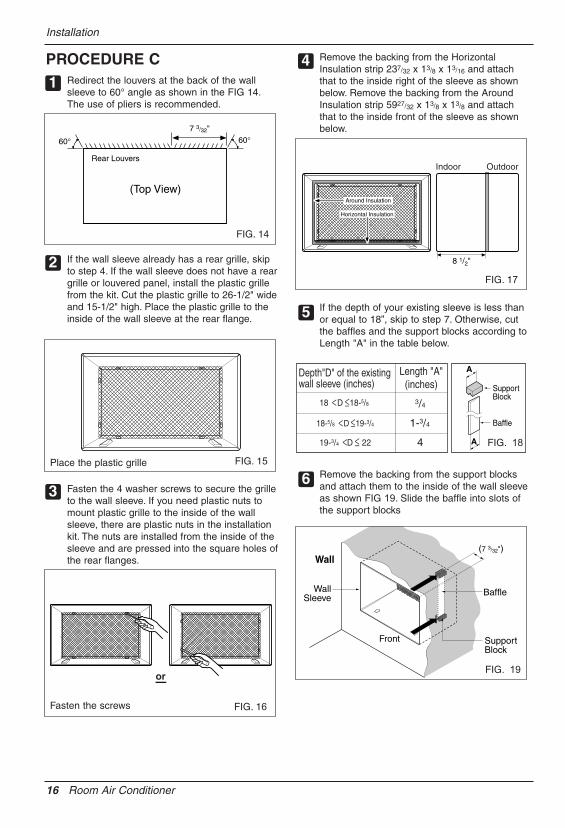
PULL OPEN / PUSH CLOSE
Ventilation
Air Direction
The ventilation lever is located in the right of the air discharge.The ventilation lever must be in the CLOSE position in order tomaintain the best cooling conditions.When fresh air is necessary in the room, set the ventilation lever tothe OPEN position.The damper is opened and room air is exhausted outside.
The direction of air can be controlled wherever you want by adjusting the horizontal louver and the vertical louver.
• HORIZONTAL AIR-DIRECTIONCONTROL
The horizontal air direction is adjusted by movingvertical louver.The lever of vertical louver is located in the right andleft side of the air discharge.
• VERTICAL AIR-DIRECTION CONTROL
The vertical air direction is adjusted by moving thehorizontal louver.
How to insert Batteries
1. Remove the cover from the back of the remotecontroller.
2. Insert two batteries.• Be sure that the (+) and (-) directions are
correct.• Be sure that both batteries are new.
3. Re-attach the cover.
• Do not use rechargeable batteries.Such batteries differ from standarddry cells in shape, dimensions, andperformance.
• Remove the batteries from theremote controller if the airconditioner is not going to be usedfor an extended length of time.

Owner’s Manual 21
ENG
LISHMaintenance and Service
Maintenance and Service
Air Filter Cleaning
How to Attach Front Grille to Cabinet
TURN THE AIR CONDITIONER OFF AND REMOVE THE PLUG FROM THE POWER OUTLET.
The air filter should be checked at least twice a month to see if cleaning is necessary.Trapped particles in the filter will build up and block the airflow. This reduces the coolingcapacity and also causes an accumulation of frost on the cooling coils.If the filter becomes turn or damaged you should replaceimmediately. Replacement filters are available from yoursalesperson, dealer, and the authorized customer servicecenters.
1. Open the inlet grille downward by pulling out the top of theinlet grille.
2. Remove the air filter from the front grille assembly bypulling the air filter up slightly.
3. Wash the filter using lukewarm water below 40°C (104°F).
4. Gently shake the excess water from the filter completely.Replace the filter.
The front grille can be removed for cleaning or to check the model and serial numbers.For your safety, you should attach the front grille as the following procedures.
1. Pull down front grille from the cabinet top.
2. Push front grille’s tips toward the cabinet inorder to insert front grille’s tabs into thecabinet.
3. Open the inlet grille.
4. Tighten the screw through the front grille intothe plate of control box.
5. Close inlet grille.
MODE TIMER POWERFAN
SPEED
Fan
EnergySaver
Cool
Timer TEMP
'FF1 LOWF2 MEDF3 HIGH
22 Room Air Conditioner
Maintenance and Service
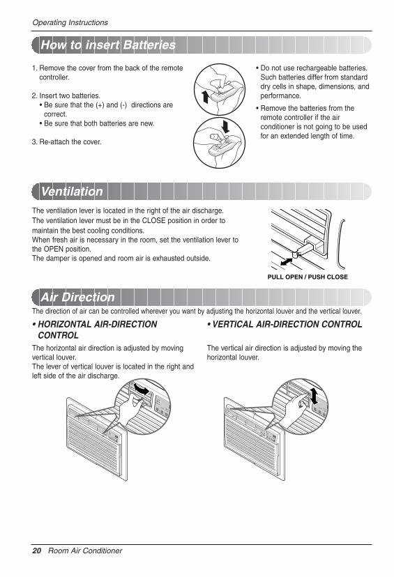
Common Problems and Solutions
Troubleshooting
Normal Operation
Troubleshooting Tips Save time and money!Review the chart below first and you may not need to call for service.
• You may hear a pinging noise caused by water being picked up and thrown against the condenser on rainydays or when the humidity is high. This design feature helps remove moisture and improve efficiency.
• You may hear the thermostat click when the compressor cycles on and off.• Water will collect in the base pan during high humidity or on rainy days. The water may overflow and drip from
the outdoor side of the unit.• The fan may run even when the compressor does not.
Problem Possible Causes What To Do
� The air conditioner isunplugged.
� The fuse is blown/circuitbreaker is tripped.
� Power failure.
� The current interrupterdevice is tripped.
� Airflow is restricted.
� TEMP Control set toohigher number.
� The air filter is dirty.
� The room may have beenhot.
� Cold air is escaping.
� Cooling coils have iced up.
� Ice blocks the air flow andstops the air conditionerfrom cooling the room.
• Make sure the air conditioner plug is pushedcompletely into the outlet.
• Check the house fuse/circuit breaker box and replacethe fuse or reset the breaker.
• If power failure occurs, turn the mode control to OFF.When power is restored, wait 3 minutes to restart theair conditioner to prevent tripping of the compressoroverload.
• Press the RESET button located on the power cordplug. If the RESET button will not stay engaged,discontinue use of the air conditioner and contact aqualified service technician.
• Make sure there are no curtains, blinds, or furnitureblocking the front of the air conditioner.
• Set the TEMP control to a lower number.
• Clean the filter at least every 2 weeks.See the operating instructions section.
• When the air conditioner is first turned on,you need to allow time for the room to cool down.
• Check for open furnace floor registersand cold air returns.
• Set the air conditioner's vent to the closed position.
• See Air Conditioner Freezing Up below.
• Set the mode control at High Fan or High Cool withthe high temperature.
Air conditionerdoes not start
Air conditionerdoes not cool as itshould
Air conditionerfreezing up

Memo
Owner’s Manual 23
ENG
LISH
24 Aire Acondicionador
Manual del usuario del acondicionador de aire tipo Ventana
TABLA DE CONTENIDOSPARA SUS ARCHIVOSEscriba aquí el modelo y número de serie:
Modelo n°:
Serie n°:
Puede encontrar estos datos en la etiqueta situada en ellateral de cada unidad.
Nombre del distribuidor:
Fecha de compra:
� Adjunte su recibo a esta página con la grapadora parael momento que lo necesite para probar la fecha de suadquisición o para la validación de la garantía.
LEA ESTE MANUALEn su interior encontrará muchos consejos útiles sobre lautilización y mantenimiento de su acondicionador de aire.Unos pocos cuidados por su parte le pueden ahorrarmucho tiempo y dinero durante la vida de suacondicionador de aire.En la tabla de consejos para la solución rápida deproblemas encontrará muchas respuestas a los problemasmás habituales. Si revisa primero nuestra Tabla deConsejos para la solución rápida de problemas, tal vez nonecesite llamar nunca al servicio técnico.
PRECAUCIÓN• Póngase en contacto con un técnico del servicio
autorizado para realizar la reparación ymantenimiento de esta unidad.
• Póngase en contacto con un instalador para realizarla instalación de esta unidad.
• Cuando se va a cambiar el cable eléctrico, el trabajode reemplazamiento debe ser realizado únicamentepor personal autorizado, utilizando las piezas decambio genuinas únicamente.
• El trabajo de reemplazamiento debe ser realizado deacuerdo con el Código Eléctrico Nacionalúnicamente por personal autorizado.
Precauciones de Seguridad .........25
Antes de poner el equipo enfuncionamiento..............................29
Introducción...................................30
Seguraida Electrica .......................31
Instalacion......................................33
Instruccionnes deFuncionamiento.............................40
Cuidado y Mantenimiento ............43

Manual del Propietario 25
ESPAÑ
OL
Precauciones de Seguridad
Precauciones de SeguridadPara evitar lesiones al usuario o a otras personas y daños a la propiedad, estas instruccionesestén seguirse.� Una operación incorrecta por ignorar las instrucciones provocará lesiones o daños. La seriedad se clasifica
por las siguientes indicaciones.
� Significados de los símbolos utilizados en este manual.
ADVERTENCIA
PRECAUCION
Este símbolo indica la posibilidad de muerte o de seria lesión.
Este símbolo indica sólo la posibilidad de lesiones o daños a la propiedad
ADVERTENCIA� Instalación
No hacer.
Siga estas instrucciones.
No utilice un cable dealimentación, enchufe o unatoma suelta que esté dañada.
• De lo contrario, podría provocarun incendio o descargaeléctrica.
Enchufe siempre a untomacorriente que tengatoma a tierra.
• De lo contrario, podría provocarun incendio o descargaeléctrica.
No modifique ni alargue elcable de alimentación.
• De lo contrario, puede provocaruna descarga eléctrica oincendio debido a lageneración de calor.
No desmonte ni modifiquelos productos.
• Puede ocasionar fallos y unadescarga eléctrica.
Tenga cuidado aldesembalar e instalar elaparato.
• Los bordes afilados puedenprovocar lesiones.
No use el cable de alimentacióncerca gas inflamable omateriales combustibles talescomo la gasolina, benceno,disolvente, etc.
• Podría ocurrir una explosión oincendio.
Gasolin

26 Aire Acondicionador
Precauciones de Seguridad
� Operación
No ponga el cable dealimentación cerca de uncalentador.
• Puede ocasionar un incendio yuna descarga eléctrica.
No permita que entre aguaen las piezas eléctricas.
• Puede provocar fallos en elproducto o descargaseléctricas.
Utilice un paño suave paralimpiar. No utilice cera,disolventes o detergentesfuertes.
• La apariencia del aparato de aireacondicionado puede deteriorar,cambiar el color o desarrollar flujosen lassuperficies.
Wax Thinner
Ventile bien la sala al usareste aparato con una estufa,etc.
• Puede ocurrir un falta deoxígeno.
Apague el aparato y elinterruptor diferencialprimero antes de limpiar launidad.
• Debido a que el ventilador gira aalta velocidad durante elfuncionamiento, podría ocasionarlesiones.
Apague el interruptor dealimentación principal cuandono vaya a utilizar el aparatodurante mucho tiempo.
• Evitará el arranque accidental yla posibilidad de lesiones.
Desenchufe la unidad si oyeun sonido extraño, olores, osi observa salir humo.
• De lo contrario, puede ocurrirun incendio y un accidente pordescarga eléctrica.
No abra la parrilla deentrada al aparato mientrasestá en funcionamiento.
• De lo contrario, pueden ocurrirdescargas eléctricas y fallos.
Si entra agua en el producto,apague el interruptor de lacarcasa principal del aparato.Póngase en contacto con elcentro de servicio después dehaber sacado el enchufe deltomacorriente.
No use el cable de alimentacióncerca gas inflamable o materialescombustibles tales como lagasolina, benceno, disolvente, etc.
• Puede ocasionar una explosióno descarga eléctrica.
No comparta eltomacorriente con otroselectrodomésticos.
• De lo contrario, puede provocar unadescarga eléctrica o incendio debidoa la generación de calor.
Saque el enchufe en caso denecesidad, sosteniendo lacabeza del enchufe y no lotoque con las manos mojadas.
• De lo contrario, podría provocar unincendio o descarga eléctrica.

Manual del Propietario 27
ESPAÑ
OL
Precauciones de Seguridad
ADVERTENCIA� Instalación
No opere ni detenga launidad insertando oestirando de enchufe.
• De lo contrario, puede provocaruna descarga eléctrica oincendio debido a lageneración de calor.
No dañe ni use un enchufede alimentación noespecificado.
• Provocará descargas eléctricaso incendios.
No toque el producto conlas manos mojadas o en unambiente húmedo.
• Provocará descargaseléctricas.
Sostenga el enchufe por sucabeza al sacarlo.
• Podría ocasionar una descargaeléctrica y daños.
Cuando haya un escape degas, abra la ventana paraventilar antes de poner enmarcha la unidad.
• De lo contrario, podría ocurriruna explosión o incendio.
No toque las partesmetálicas del aparato alsacar el filtro del aire.
• Son puntiagudas y puedenprovocar lesiones.
Instale el producto de modo que el ruido oel aire caliente producido por la unidadexterna no moleste a los vecinos.
• De lo contrario puede dar lugar a disputasvecinales.
Mantenga nivelado el producto al instalarlo.
• De lo contrario se podría causar vibraciones oescapes de agua.

28 Aire Acondicionador
Precauciones de Seguridad
No se suba a la unidadinterior/exterior ni coloqueobjetos sobre la misma.
• Puede lesionarse al caerse delaparato o al caerse los objetosque haya colocado.
Inserte siempre el filtrocorrectamente.Límpielo cada dos semanas.
• El funcionamiento sin filtrospuede provocar fallos.
No beba el agua que drenael aparato de aireacondicionado.
No ponga plantas nianimales en la trayectoriaque recorrerá el airecaliente.
• Podría ocasionar lesiones.
No bloquee la entrada ni lasalida del flujo de aire.
• Puede causar una avería en elaparato.
Utilice un paño suave paralimpiar. No utilice cera,disolventes o detergentesfuertes.
• La apariencia del aparato de aireacondicionado puede deteriorar,cambiar el color o desarrollar flujosen las superficies.
Tenga cuidado para notocar los bordespuntiagudos al instalar.
• Podría ocasionar lesiones.
Evite un enfriamientoexcesivo y ventile enocasiones.
• De lo contrario, podría dañar susalud.
No introduzca la mano nibarras en la entrada o salidadel aire durante elfuncionamiento del aparato.
• De lo contrario, podrían ocurrirlesiones personales.
� Operación

Antes de poner el equipo en funcionamiento
Manual del Propietario 29
ESPAÑ
OL
Antes de poner el equipo en funcionamiento
1. Póngase en contacto con un especialista para realizar la instalación.2. Enchufe correctamente la toma de alimentación.3. Utilice un circuito dedicado.4. No utilice un cable alargador.5. No inicie/cese el funcionamiento enchufando/desenchufando el cable
eléctrico.6. Si el cable/enchufe está dañado, sustitúyalo solo por una pieza autorizada.
1. Estando expuesto a la circulación directa de aire durante un extenso períodode tiempo podría resultar peligroso para su salud. No exponga a las personas,animales domésticos, o a las plantas a la circulación de aire durante largosperíodos de tiempo.
2. Debido a la probabilidad de falta de oxígeno, ventile el cuarto cuando estéutilizado el aparato junto con estufas u otros aparatos de calefacción.
3. No utilice este aire acondicionado con propósitos especiales no especificados(Ej.: conservación de dispositivos de precisión, comida, animales domésticos,plantas y objetos de arte). Tal uso podría dañar los artículos.
1. No toque las piezas metálicas de la unidad al retirar el filtro. Manejar aristasafiladas de metal puede causar lesiones.
2. No utilice el agua para limpiar el interior del aire acondicionado. La exposiciónal agua puede destruir el aislamiento, conduciendo a posibles descargaseléctricas.
3. Al limpiar la unidad, asegúrese antes de que la electricidad y el interruptorestán apagados. El ventilador rota a muy alta velocidad durante elfuncionamiento del equipo. Existe la posibilidad de lesiones si accionaaccidentalmente la electricidad de la unidad mientras limpia el interior de launidad.
Para cuestiones de reparación y mantenimiento, póngase en contacto con sudistribuidor de servicio autorizado.
Preparación para el funcionamiento
Uso
Limpieza y mantenimiento
Servicio

30 Aire Acondicionador
Introducción
Este símbolo lo advierte de un peligro de accidente porcorriente eléctrica.
Este símbolo lo adiverte de un peligro que pueda causar undaño del ventliador.
Este símbolo significa condicciones especiales.CONSEJO
Introducción
Símbolos Utilizados en Este Manual
Características
Este aparato debería instalarse de acuerdo con las normas del Código Eléctrico Nacional.
ARMARIO
REJILLAFRONTAL
REJILLA DE ENTRADA(Toma de aire)
FILTRO DE AIRE
DEFLECTOR HORIZONTAL DE AIRE(Rejilla de ventilación vertical)
CONTROL DEL ORIFICIO DE VENTILACIÓN
DEFLECTOR VERTICAL DE AIRE(Rejilla de ventilación horizontal)
DESCARGADE AIRE
MONTAJE DEL SOPORTE DE PARED(Incluyendo rejilla posterior de aluminio)
EL SOPORTE DE PARED YLA REJILLA POSTERIOR (incluido opcionalmente con su unidad)
EL UNIDAD
REJILLA POSTERIOR(Rejilla posteriorde aluminio)

Seguraida Electrica
Manual del Propietario 31
ESPAÑ
OL
Seguraida ElectricaDatos Electricos
115V~ 230V~ El cable de alimentación puede incluir un dispositivo interruptor de corriente. La carcasa del enchufe cuenta con un botón de prueba y otro de reinicio. El dispositivo debe comprobarse periódicamente presionando primero el botón TEST y después RESET.Si el botón TEST no se desconecta o si el botón RESET no permanece activo, suspenda el uso del aire acondicionado y póngase en contacto con un técnico de servicio cualificado.
Utilice el enchufe de la pared Consumo de Energía
Standard 125V, enchufe de 3Líneas de 15A, 125V AC
Standard 250V, enchufe de 3Líneas de 15A, 250V AC
Standard 250V, enchufe de 3Líneas de 20A, 250V AC
Utilice un fusible de15AMP. o unInterruptor de 15AMP.
Utilice un fusible de20AMP. o unInterruptor de 20AMP.
No presione nunca el botón de prueba durante elfuncionamiento, de lo contrario el enchufe podríaresultar dañado.Este dispositivo contiene productos químicos,incluyendo plomo, conocido en el estado deCalifornia como producto cancerígeno y causante dedefectos de nacimiento y otros daños al sistemareproductor.Lávese bien las manos tras manipular el dispositivo.No desmonte, modifique ni sumerja en agua esteenchufe.Si el dispositivo se activara, deberá corregir la causaantes de volver a utilizarlo.
Los hilos conductores dentro del cable están rodeadospor blindajes, que supervisan la corriente de fuga.Estos blindajes no están puestos a tierra.
Examine periódicamente el cable en busca decualquier daño. No utilice este producto si los blindajesresultaran expuestos.Evite el riesgo de descargas eléctricas; esta unidad nopuede ser reparada por el usuario por ser resistente ya prueba de alteraciones. Manipular la porción selladade la unidad anulará todas las garantías y quejas derendimiento. Esta unidad no está diseñada para su usocomo un interruptor de encendido-apagado.
La forma puede ser diferente según su modelo.
CONSEJO
NO USE CABLE DE EXTENSIÓN EN UNIDADESDE 208, 230, AND 208/230 VOLTIOS.Todo el cableado deberá realizarse de acuerdocon los códigos y reglamentos eléctricoslocales.
El cableado doméstico de aluminio podríaocasionar problemas especiales. Consulte a unelectricista calificado.
CONSEJO

32 Aire Acondicionador
Seguraida Electrica
IMPORTANTE(FAVORLEA CON ATENCIÓN)POR LA SEGURIDAD PERSONAL DEL USUARIO,ESTE APARATO DEBE SER DEBÍDAMENTENEUTRALIZADO.
El cordón de energía de éste aparato estaequipado con tres patas(cable a tierra). Utiliceéste con un enchufe de pared de tres salidas(atierra) para minimizar el peligro de choqueeléctrico. El cliente debe revisar el receptor depared y el circuito por un electricista calificadopara asegurarse que la recepción estadebidamente neutralizada.
NO CORTE O REMUEVA LA TERCERAPATA(GROUND) DEL ENCHUFE.
A. SITUACIONES EN LAS CUALES ELAPARATO ES DESCONECTADOOCASIONALMENTE:
Debido al peligro potencial, nosotros norecomendamos el uso de adaptadores. Sinembargo, si usted desea utilizar un adaptador,una CONEXIÓN TEMPORAL, puede serefectuada. Utilice adaptadores UL, disponiblesen la mayoría de los estable cimientos deherramientas. La pata mas grande deladaptador debe ser alineada con la pata masgrande del interruptor para asegurarse unapolarización adecuada.
Adaptar la terminal del ground deladaptador a la cubierta de la pared con untornillo no neutraliza el aparato a menosque la cubierta del tornillo sea de metal, uno sea insolada, y el receptor de paredesteneutralizado a través del alambrado del lacasa. El cliente debe hacer verificar elcircuito por un electricista calificado paraasegurarse que el receptor estadebidamente neutralizado.
Desconecte el cordón de energía del adaptador,utilizado una mano en cada uno. De lo contrario,la terminal del adaptador puede romperse. NOUTILICE el aparato con un enchufe roto.
B. SITUACIONES EN LAS CUALES ELAPARATO ES DESCONECTADO CONFRECUENCIA.
No utilice un adaptador en estascircunstancias. Desconectar el cordón deenergía con frecuencia lo llevará al eventualrompimiento de la terminal de neutralización.La saluda de energía de la pared debe serreemplazada por una salida de trespatas(neutralizada).
USO DE EXTENSIONESDebido al peligro potencial, no recomendamosla utilización de extensiones. Sin embargo, siusted desea utilizar una extensión, utilice unacertificada por CSA/UL de tres alambres,catalogada 15A, 250V.
Seguraida Electrica

Manual del Propietario 33
ESPAÑ
OL
Instalacion
InstalacionRetire los materiales de embalaje del soporte de pared depared y la cinta del aire acondicionado.
REQUISITOS DE INSTALACIÓNSi utiliza un soporte de pared de pared ya existente,deberá medir sus dimensiones. Instale el nuevo aireacondicionado según estas instrucciones de instalaciónpara lograr el mejor funcionamiento. Todos los soporte depared de pared utilizados para montar el nuevo aireacondicionado deben estar en buenas condicionesestructurales y contar con una rejilla trasera para conectarel nuevo aire acondicionado de forma segura. (FIG. 1)Con el soporte de pared LGE (incluido opcionalmentecon su unidad), podrá mantener el mejor rendimiento delnuevo aire acondicionado. (FIG. 2)
SERVICIO ELÉCTRICOCompruebe su servicio eléctrico disponible. La fuente dealimentación disponible debe ser igual que la que semuestra en la placa de identificación de la unidad(encontrada en el lado izquierdo de la carcasa).
Todos los modelos están equipados con un enchufe detres dientes para proporcionar el servicio apropiado yponer a tierra el positivo de forma segura. No cambie elenchufe de ninguna manera. No utilice un enchufeadaptador. Si su enchufe de pared actual no admite suenchufe, llame a un electricista cualificado para realizarlas correcciones necesarias. GUARDE LA CAJA DECARTÓN para el almacenamiento y este MANUAL DELPROPIETARIO para futuras referencias. El cartón es lamejor manera de almacenar la unidad durante el inviernoo cuando no esté en uso.
HARDWARE DE INSTALACIÓN
14-13/32"(366 mm)
24"(610 mm)
18-15/32"(468 mm)
20-3/32"(511 mm)
15
6
7
8
3
2 4
9
2 opciones de tamaño
2 opciones de tamaño
• Guantes ceñidosadecuados
• Destornillador estándar• Destornillador de estrella• Alicates• Cuchillo afilado
• Llave inglesa abierta oajustable de 3/8-pulgadas
• Enchufe y carrete de tuercahexagonal de 1/4- pulgadas
• Cinta métrica• Taladro eléctrico• Boca de taladro de 1/4-
pulgadas
FIG. 1Aire acondicionado
ARTÍCULO NOMBRE DE LAS PIEZAS Q'TY1 REJILLA DE PLÁSTICO 12 TIRA VERTICAL DE AISLAMIENTO 13 TIRAS ENVOLVENTES DE AISLAMIENTO 24 TIRA HORIZONTAL DE AISLAMIENTO 15 BLOQUE DE APOYO 26 COMPUERTA 17 MARCO DE AJUSTE 28 CUÑA 29 TUERCAS DE PLÁSTICO Y TORNILLOS DE ARANDELA 4
15-17/32"(394 mm)
16-23/32"(425 mm)
25-7/8"(656 mm)
Rejilla de aluminio
FIG. 2Soporte de paredLGE
Para evitar riesgos de daños corporales, materiales, o dañosal producto debidos al peso de este dispositivo y a los bordesafilados que pueden estar expuestos:• Los aires acondicionados tratados en este manual
representan un peligro por peso excesivo. Son necesariasdos o más personas para desplazar e instalar la unidad.Para evitar lesiones o grandes esfuerzos, utilice las técnicasde elevación y desplazamiento para mover la unidad.
• Examinar cuidadosamente la ubicación donde el aireacondicionado vaya a ser instalado. Asegúrese de queaguantará el peso de la unidad a lo largo de un extensoperíodo de tiempo.
• Manipule con cuidado el aire acondicionado. Utilice losguantes protectores siempre que levante o desplace launidad. EVITE las aristas afiladas de metal de las bobinasfrontal y posterior.
• Asegúrese de que el aire acondicionado no se caiga durantela instalación.
HERRAMIENTAS NECESARIAS:

34 Aire Acondicionador
Instalacion
INSTALACIÓN
• Escoja una ubicación que permita al aire acondicionadosoplar hacia el área que desee. Una buena instalación,prestando especial atención a la posición correcta de launidad reducirá la necesidad de reparaciones.
ARTÍCULOS EN EL HARDWARE DEINSTALACIÓNUsted puede no necesitar todas las piezas del conjunto.Descarte las piezas que no utilice
CÓMO INSTALARIdentifique el soporte de pared existente antes deinstalar la unidad según la lista.
Todos los soporte de pared utilizados para montar elnuevo aire acondicionado deben estar en condicionesestructurales sanas y tener una rejilla posterior que seacople con seguridad al soporte de pared, o una pestañaposterior que sirva como freno para el aireacondicionado.
Desmonte el antiguo aire acondicionado del soportede pared existente.
Limpie el interior del soporte de pared existente. (Notoque el sellado.)
El soporte de pared se estar firmemente sujeto a la paredantes de instalar el aire acondicionado. Utilice los clavos otornillos a través del soporte de pared, si fuera necesario.Vuelva a pintar el soporte de pared si fuera necesario.
Prepare el soporte de pared para la instalación de launidad. Si usted piensa utilizar el soporte de paredexistente, y no es LGE, utilice el procedimiento B ó Ca continuación.
Instale la nueva unidad en el soporte de pared.
Al finalizar la instalación, la unidad de sustitución DEBEtener una pendiente hacia atrás según se ilustra. Paralograr una pendiente de 1/4", retire el envoltorio de lascuñas de 11-13/16" y acóplelas según se muestra acontinuación en la FIG. 3. Coloque el extremo más altode la cuña en la parte frontal de la base del soporte depared.
CONSEJO
1
2
3
4
5
6
1/4"
Soportede pared
FRENTAL
UNIDAD
COLOCACIÓN DE LA CUÑA INSTALACIÓN DE LA UNIDAD
1"dealto 3/4"de alto
Cuña
6" 6"
FIG. 3
Recomendamos encarecidamente que desmonte el viejosoporte de pared y la instalación de un nuevo soportede pared LGE.Si decide mantener el soporte de pared existente, tendráque redireccionar las rejillas de ventilación en la parteposterior de la ilustración del soporte de pared.Recomendamos el uso de alicates. Si NO las redirecciona,corre el riesgo de un rendimiento pobre o de averías en elproducto.Estas no están cubiertas bajo los términos de garantía deLGE.
ARTÍCULO (pulgadas) Cant.Rejilla plástica 263/4 x 161/2 1Tira vertical de aislamiento 159/16 x 13/8 x 13/8 1Tiras de aislamiento 671/8 x 13/8 x 25/32 1envolventes 5927/32 x 13/8 x 13/8 1Tira horizontal de aislamiento 237/32 x 13/8 x 13/16 1Bloque de apoyo 13/4 x 13/8 x 45/16 2Compuerta 14 x 41/2 x 1/8 1Cuña 1113/16 x 1 x 3/4 2Marco de ajuste 2Tornillos de arandela 4Tuercas (Plástico) 4Rejilla posterior 1
Marca Dimensiones del soporte de pared (pulgadas)Ancho Altura Profundidad
White-Westinghouse25-1/2 15-1/4 16, 17-1/2Frigidaire ó 22
Carrier (Serie 52F)General Electric
26 15-5/8 16-7/8/Hotpoint
Whirlpool 25-7/8 16-1/2 17-1/8ó 23
Fedders/Emerson 27 16-3/4 16-3/4ó 19-3/4
LGE 25-7/8 15-17/32 16-23/32Emerson/Fedders 26-3/4 15-3/4 15Carrier (Serie 51S) 25-3/4 16-7/8 18-5/8Friedrich 27 16-3/4 16-3/4
Procedimiento Marca Profundidad (pulgadas)A LGE 16-23/32
White-WestinghouseFrigidaire Carrier 16, 17-1/2
Carrier (Serie 52F) ó 22
B General Electric 16-7/8/HotpointWhirlpool 17-1/8 ó 23Carrier (Serie 51S) 18-5/8
Fedders/Emerson 16-3/4ó 19-3/4
C Emerson/Fedders 15Friedrich 16-3/4

Manual del Propietario 35
ESPAÑ
OL
Instalacion
PROCEDIMIENTO ASi está utilizando un nuevo soporte de pared(incluido opcionalmente con su unidad), salte alpaso 3. Si no es así, instale la rejilla plástica. Cortela rejilla plástica a 25-1/2" de ancho y 15-1/4” dealto. Coloque la rejilla plástica en el interior delsoporte de pared en la pestaña posterior.
Apriete los 4 tornillos de la arandela para asegurar larejilla al soporte de pared. Si necesita tuercasplásticas para montar la rejilla plástica en el interiordel soporte de pared, encontrará tuercas plásticasen el equipo de instalación. Las tuercas estáninstaladas en el interior del soporte de pared y estánpresionando las perforaciones rectangulares de laspestañas posteriores.
Retire el envoltorio de la tira vertical de aislamiento15-9/16 x 1-3/8 x 1-3/8 y únala a la parte interiorderecha del soporte de pared según se muestra acontinuación. Retire el envoltorio de la tira deaislamiento envolvente de 67-1/8 x 1-3/8 x 25/32 yúnala a la parte frontal interior del soporte de paredsegún se muestra a continuación.
Instale la nueva unidad en el soporte de pared.
Para el montaje, encaje la lengüeta de cada piezaen la ranura de la otra pieza según se muestra acontinuación. Deslice la pieza sobre la parte frontaldel aire acondicionado hasta que el ajuste searasante con el soporte de pared según se muestra acontinuación.
FIG. 4
Aislamiento envolvente
Aislamiento vertical
9 1/2" 6"
Interior Exterior
FIG. 6
ó FIG. 5
1
2
3
4
5
Pared
Ajuste (2EA)
FIG. 7
• Los aires acondicionados tratados en este manualrepresentan un peligro por peso excesivo. Sonnecesarias dos o más personas para desplazar einstalar la unidad. Para evitar lesiones o esfuerzosexcesivos, utilice las técnicas de levantamiento ydesplazamiento apropiadas al mover la unidad.
• Manipule con cuidado el aire acondicionado, tengacuidado de evitar cortes de las aristas afiladas demetal de las bobinas frontal y posterior.
• Asegúrese de que el aire acondicionado no se caiga aldesmontarlo.
• Si la unidad no funciona tras la revisión de instalación,asegúrese que el interruptor del circuito no se hadisparado. Consulte la guía de solución de averíaspara conocer el procedimiento de reinicio.

36 Aire Acondicionador
Instalacion
PROCEDIMIENTO BRedireccione las rejillas de ventilación en la parteposterior del soporte de pared a un ángulo de 60°según muestra la FIG. 8. Recomendamos el uso dealicates.
Si el soporte de pared ya cuenta con una rejillaposterior, salte al paso 4. Si el soporte de pared notiene una rejilla posterior o un panel en rejilla, instalela rejilla plástica del conjunto. Corte la rejilla plásticaa 25-1/2" de ancho y 15-1/4” de alto. Coloque larejilla plástica en la parte interior del soporte depared en la pestaña posterior.
Apriete los 4 tornillos de la arandela para asegurar larejilla al soporte de pared. Si necesita tuercasplásticas para montar la rejilla plástica en el interiordel soporte de pared, encontrará tuercas plásticasen el equipo de instalación. Las tuercas estáninstaladas en el interior del soporte de pared y estánpresionando las perforaciones cuadradas de laspestañas posteriores.
Retire el envoltorio de la tira vertical de aislamiento15-9/16 x 1-3/8 x 1-3/8 y únala a la parte interiorderecha del soporte de pared según se muestra acontinuación. Retire el envoltorio de la tira deaislamiento envolvente de 67-1/8 x 1-3/8 x 25/32 yúnala a la parte frontal interior del soporte de paredsegún se muestra a continuación.
Si la profundidad de su soporte de pared es menor oigual a 18", salte al paso 6. Si no, corte lascompuertas y los bloques de soporte según lalongitud "A" en la tabla a continuación.
14
2
3
FIG. 9
Aislamiento envolvente
Aislamiento vertical
9 1/2" 6"
Interior Exterior
FIG. 11
ó
FIG. 10
Rejillas de ventilación posteriores
(Perspectiva superior)
60° 60°7 3/32"
FIG. 8
Profundidad "D" del soporte de pared existente (pulgadas)
Longitud "A"(pulgadas) Bloque
de apoyo
Compuerta
A
A
3/4
1-3/4
4
18 D 18-5/8
18-5/8 D 19-3/4
19-3/4 D 22
5Coloque la rejilla plástica
Apriete los tornillos
FIG. 12

Manual del Propietario 37
ESPAÑ
OL
Instalacion
PROCEDIMIENTO BRetire el envoltorio de los bloques de apoyo yacóplelos al interior del soporte de pared comomuestra la FIG. 13. Deslice la compuerta en lasranuras de los bloques de apoyo.
Instale la nueva unidad en el soporte de pared.
Ajuste la posición según describe el paso 5 ,procedimiento A.8
Pared
Soportede pared Compuerta
(7 3/32")
Frontal Bloquede apoyo
FIG. 13
6
7
• Los aires acondicionados tratados en este manualrepresentan un peligro por peso excesivo. Sonnecesarias dos o más personas para desplazar einstalar la unidad.Para evitar lesiones o esfuerzos excesivos, utilicelas técnicas de levantamiento y desplazamientoapropiadas al mover la unidad.
• Manipule con cuidado el aire acondicionado, tengacuidado de evitar cortes de las aristas afiladas demetal de las bobinas frontal y posterior.
• Asegúrese de que el aire acondicionado no secaiga al desmontarlo.
• Si la unidad no funciona tras la revisión deinstalación, asegúrese que el interruptor del circuitono se ha disparado. Consulte la guía de solución deaverías para conocer el procedimiento de reinicio.

38 Aire Acondicionador
Instalacion
PROCEDIMIENTO CRedireccione las rejillas de ventilación en la parteposterior del soporte de pared a un ángulo de 60°según muestra la FIG. 14. Recomendamos el uso dealicates.
Si el soporte de pared ya cuenta con una rejillaposterior, salte al paso 4. Si el soporte de pared notiene una rejilla posterior o un panel en rejilla, instalela rejilla plástica del conjunto. Corte la rejilla plásticaa 26-1/2" de ancho y 15-1/2” de alto. Coloque larejilla plástica en la parte interior del soporte depared en la pestaña posterior.
Apriete los 4 tornillos de la arandela para asegurar larejilla al soporte de pared. Si necesita tuercasplásticas para montar la rejilla plástica en el interiordel soporte de pared, encontrará tuercas plásticasen el equipo de instalación. Las tuercas estáninstaladas en el interior del soporte de pared y estánpresionando las perforaciones cuadradas de laspestañas posteriores.
Retire el envoltorio de la tira horizontal de aislamientode 23-7/32 x 1-3/8 x 1-3/16 y únala a la parte interiorderecha del soporte de pared según se muestra acontinuación. Retire el envoltorio de la tira deaislamiento envolvente de 59-27/32 x 1-3/8 x 1-3/8 yúnala a la parte frontal interior del soporte de paredsegún se muestra a continuación.
Si la profundidad de su soporte de pared es menor oigual a 18", salte al paso 7. Si no, corte lascompuertas y los bloques de apoyo según la longitud"A" en la tabla a continuación.
Retire el envoltorio de los bloques de apoyo y únalosal interior del soporte de pared como muestra la FIG.19. Deslice la compuerta dentro de las ranuras enlos bloques de apoyo.
Profundidad "D" del soporte de pared existente (pulgadas)
Longitud "A"(pulgadas) Bloque
de apoyo
Compuerta
A
A
3/4
1-3/4
4
18 D 18-5/8
18-5/8 D 19-3/4
19-3/4 D 22
Pared
Soportede pared Compuerta
Frontal Bloquede poyo
(7 3/32")
FIG. 19
FIG.18
14
2
3
FIG. 15
8 1/2"
Interior Exterior
Aislamiento envolvente
Aislamiento horizontal
FIG. 17
óFIG. 16
Rejillas de ventilación posteriores
(Perspectiva superior)
60°7 3/32"
60°
FIG. 14
5
6Coloque la rejilla plástica
Apriete los tornillos

Instalacion
Manual del Propietario 39
ESPAÑ
OL
PROCEDIMIENTO CPara lograr una pendiente de posterior para eldrenaje de la unidad, retire el envoltorio de lascuñas de 11-13/16" y acóplelas según se muestraa continuación en la FIG. 21. Coloque el extremomás alto de la cuña en la parte frontal de la basedel soporte de pared.
Instale la nueva unidad en el soporte de pared.
Monte el ajuste según lo descrito en el paso 6,procedimiento A.
8
7
FIG. 20
1" dealto 3/4"
de alto
Cuña (2EA)
6" 6"
FIG. 21
• Los aires acondicionados tratados en este manualrepresentan un peligro por peso excesivo. Sonnecesarias dos o más personas para desplazar einstalar la unidad.Para evitar lesiones o esfuerzos excesivos, utilicelas técnicas de levantamiento y desplazamientoapropiadas al mover la unidad.
• Manipule con cuidado el aire acondicionado, tengacuidado de evitar cortes de las aristas afiladas demetal de las bobinas frontal y posterior.
• Asegúrese de que el aire acondicionado no secaiga al desmontarlo.
• Si la unidad no funciona tras la revisión deinstalación, asegúrese que el interruptor del circuitono se ha disparado. Consulte la guía de soluciónde averías para conocer el procedimiento dereinicio.
9

40 Aire Acondicionador
Instruccionnes de Funcionamiento
Instruccionnes de FuncionamientoControles
La apariencia de los controles será como uno de los siguientes.
MODE TIMER POWERFAN
SPEED
Fan
EnergySaver
Cool
Timer TEMP
'FF1 LOWF2 MEDF3 HIGH
RECEPTOR DE SEÑAL DEL MANDOA DISTANCIA
ENERGÍA
MODO - Presione este botón para cambiar el modo de funcionamiento de COOL � ENERGY SAVER � FAN.
- COOL (frío): • El ventilador funciona continuamente en enfriamiento normal.
- ENERGY SABER (ahorro de energía):• El ventilador para su funcionamiento cuando el compresor cesa de enfriar. El ventilador se encenderá y la unidad
comprobará la temperatura del aire de la habitación aproximadamente cada 3 minutos para determinar si es necesario seguir enfriando.
- FAN (ventilador): • Sólo está en funcionamiento el ventilador.
TEMPORIZADOR- HORA DE APAGADO
• Normalmente utilizará el tiempo de apagado mientras usted duerme.
• Si la unidad está funcionando, utilice el temporizador para fijar el número de horas hasta que se apague.
• Para su tranquilidad al dormir, una vez que el temporizador esté configurado, el control de temperatura se elevará hasta los 2° F tras 30 minutos y de nuevo tras otros 30 minutos.
• Presione el botón del temporizador para avanzar el ajuste de 1 hora � 2 horas � … � 12 horas máximo.
- HORA DE INICIO • Si la unidad está apagada, utilice el temporizador para establecer el número de horas antes de iniciar la unidad. • Presione el botón del temporizador para adelantar el ajuste de 1 hora � 2 horas � … � 12 horas máximo.
AJUSTE DE TEMPERATURA• Utilice este botón para controlar
automáticamente la temperatura del cuarto. La temperatura puede establecerse dentro de una gama de 60° F a 86° F mediante incrementos de 1° F.
• El ajuste se muestra en pantalla.
• Para ENCENDER el aire acondicionado, presione este botón. Para APAGAR el aire acondicionado, presione de nuevo el botón.
• Este botón tiene prioridad sobre cualquier otro botón.
• Cuando la encienda por primera vez, la unidad estará en modo frío, alta velocidad del ventilador, control de temperatura en 72° F.
VELOCIDAD DEL VENTILADOR• Cada vez que presione este botón, el ajuste cambiará como sigue a continuación: {Alto � Bajo � Medio � Alto}
REINICIO AUTOMÁTICO
Cuando se restablezca la alimentación después de un corte en el suministro, la unidad empezará afuncionar con su último ajuste.

Manual del Propietario 41
ESPAÑ
OL
Instruccionnes de Funcionamiento
Control remotoEl mando a distancia y el panel de control se parecerán a los de las siguientes imágenes.
Power
Temp
Fan Speed
Timer Mode
ENERGÍA• Presione este botón para ENCENDER el aire acondicionado.
Para APAGAR el aire acondicionado vuelva a presionar el botón. • Este botón tiene prioridad sobre cualquier otro botón. • Al encenderla por primera vez, la unidad se encuentra en modo frío, alta
velocidad del ventilador, ajuste de temperatura a 72° F. • Reinicio automático
En el caso de una caída de tensión, la unidad funcionará bajo la configuración anterior una vez que la tensión vuelva a ser la normal.
AJUSTE DE TEMPERATURA • Utilice este botón para controlar automáticamente la temperatura del cuarto.
La temperatura puede establecerse dentro de una gama de 60° F a 86° F por incrementos de 1° F.
• El ajuste aparece en pantalla.
VELOCIDAD DEL VENTILADOR• Cada vez que presione este botón, el ajuste cambiará como sigue a
continuación: {Alto � Bajo � Medio � Alto}
MODO- Presione este botón para cambiar el modo de funcionamiento de COOL � ENERGY SAVER � FAN.
- COOL (frío):• El ventilador funciona continuamente en enfriamiento normal.
- ENERGY SABER (ahorro de energía): • El ventilador para su funcionamiento cuando el compresor cesa de enfriar. El ventilador se encenderá y la
unidad comprobará la temperatura del aire de la habitación aproximadamente cada 3 minutos para determinar si es necesario seguir enfriando.
- FAN (ventilador):• Sólo está en funcionamiento el ventilador.
TEMPORIZADOR- HORA DE APAGADO
• Normalmente utilizará el tiempo de apagado mientras usted duerme. • Si la unidad está funcionando, utilice el temporizador para fijar el número de
horas hasta que se apague. • Para su tranquilidad al dormir, una vez que el temporizador esté
configurado, el control de temperatura se elevará hasta los 2° F tras 30 minutos y de nuevo tras otros 30 minutos.
• Presione el botón del temporizador para avanzar el ajuste de 1 hora � 2 horas � … � 12 horas máximo.
- HORA DE INICIO • Si la unidad está apagada, utilice el temporizador para establecer el número
de horas antes de iniciar la unidad. • Presione el botón del temporizador para adelantar el ajuste de 1 hora � 2
horas � … � 12 horas máximo.
42 Aire Acondicionador
Instruccionnes de Funcionamiento
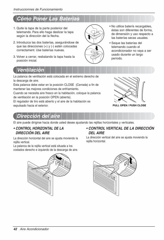
Cómo Poner Las Baterias
1. Quite la tapa de la parte posterior deltelemando. Para ello haga deslizar la tapasegún la dirección del la flecha.
2. Introduzca las dos baterías, asegurándose deque las direcciones (+) y (-) estén colocadascorrectament. Use baterías nuevas.
3. Volver a cerrar, resbalando la tapa hasta laposición inicial.
• No utilice baterís recargables,éstas son diferentes de forma,de dimensión y uso respecto alas baterías secas usuales.
• Seque las baterías deltelemando cuando elacondicionador no vaya a serusado durante un largoperíodo.
PULL OPEN / PUSH CLOSE
Ventilación
Dirección del aire
La palanca de ventilación está colocada en el extremo derecho dela descarga de aire.Esta palanca debe estar en la posición CLOSE (Cerrada) a fin demantener las mejores condiciones de enfriamiento.Cuando se necesita aire fresco en la habitación, coloque la palancade ventilación en la posición OPEN (abierta).El regulador de tiro está abierto y el aire de la habitación esexpulsado hacia el exterior.
El aire puede dirigirse hacia donde usted desee ajustando las rejillas horizontales y verticales.
• CONTROL HORIZONTAL DE LADIRECCIÓN DEL AIRE
La dirección horizontal del aire se ajusta moviendo larejilla vertical.La palanca de la rejilla vertical está situada a loscostados derecho e izquierdo de la descarga de aire.
• CONTROL VERTICAL DE LA DIRECCIÓNDEL AIRE
La dirección vertical del aire se ajusta moviendo larejilla horizontal.

Manual del Propietario 43
ESPAÑ
OL
Cuidado y Mantenimiento
Cuidado y Mantenimiento
MODE TIMER POWERFAN
SPEED
Fan
EnergySaver
Cool
Timer TEMP
'FF1 LOWF2 MEDF3 HIGH
Limpieza del filtro de aire
Como agregar la rejilla frontal al gabinete
APAGUE EL ACONDICIONADOR DE AIRE Y DESENCHÚFELO DE LA FUENTE DE PODER.
El filtro de aire debe ser controlado al menos dos veces al mes para ver si es necesaria sulimpieza.Las partículas atrapadas en el filtro pueden acumularse ybloquear el flujo del aire. Esto reduce la capacidad derefrigeración y también causa una acumulación de hieloen los sepentines de enfriamiento.Si el filtro se inutiliza o se daña, debe ser reemplazadoinmediatamente. Filtros de repuesto están disponibles en latienda donde lo compró, el representante y en los centros deservicios autorizados.
1. Abra la rejilla de entrada hacia abajo tirando de la partesuperior de la rejilla de entrada.
2. Quite el filtro de aire de la rejilla frontal tirando ligeramentedel filtro de aire.
3. Lave el filtro usando agua tibia por debajo de 40°C(104°F).
4. Sacuda suavemente el exceso de agua del filtro.Reemplace el filtro.
La rejilla frontal puede quitarse para su limpieza o para comprobar el modelo y el número deserie.Para su seguridad, debe seguir el siguiente procedimiento para colocarla.
1. Quite la parte superior de la rejilla frontal dela parte superior del gabinete.
2. Empuje los extremos frontales de la rejillahacia el gabinete a fin de insertar laspestañas de la rejilla frontal en el gabinete.
3. Abra la rejilla de entrada.
4. Ajuste los tornillos a través de la rejilla frontalen la placa de la caja de control.
5. Cierre la rejilla de entrada.

44 Aire Acondicionador
Cuidado y Mantenimiento
Problemas y soluciones habituales
Operación normal
Operación anormal
Las sugerencias para solucionar problemas ahorran tiempo y dinero !Revise la cartilla de más abajo antes de llamar al service, tal vez no tenga que hacerlo.
• Se puede oír un ruido agudo causado por el agua cuando está siendo recogida y arrojada contra elcondensador en días lluviosos o cuando la humedad es alta. Esta característica de diseño ayuda a quitar lahumedad y mejorar la eficiencia.
• Se pueden oír clicks en el termostato cuando el compresor gira hacia dentro y hacia afuera.• El agua se depositará en la bandeja de base durante los días lluviosos o de humedad alta.
El agua puede rebalsar y gotear desde el lado exterior de la unidad.• El ventilador puede funcionar aún cuando el compresor no lo hace.
Probama Causas posibles Que hacer
� El acondicionador de aireestá desenchufado.
� El fusible está quemado/elinterruptor de circuito estáabierto.
� Interrupción de la provisiónde energía eléctrica.
� El dispositivo interruptor decorriente estádesconectado.
� El flujo de aire estárestringido
� Coloque el control deTEMPERATURA en unnúmero más alto.
� El filtro de aire está sucio.
� La habitación puede haberestado caliente.
� El aire frío se escapa.
� Los serpentines deenfriamiento se hancongelado.
� El hielo bloquea el flujo deaire y no permite que elacondicionador de aireenfríe la habitación.
• Asegúrese de que el enchufe del acondicionador de airesea totalmente ajustado dentro de la salida.
• Compruebe el fusible de la casa /la caja del interruptorde circuito y reemplace el fusible o vuelva a colocar elinterruptor.
• Si se produce una interrupción de la provisión deenergía eléctrica, gire el control a OFF (apagado).Cuando la energía se restituye, espere 3 minutos parareiniciar el acondicionador de aire para prevenir que elcompresor se dispare.
• Presione el botón RESET situado en el enchufe delcable de alimentación. Si el botón RESET nopermanece activo, suspenda el uso del aireacondicionado y póngase en contacto con un técnico deservicio cualificado.
• Asegúrese de que no haya cortinas, persianas, omuebles que bloqueen la parte frontal delacondicionador de aire.
• Gire el control de TEMPERATURA a un número másbajo.
• Limpie el filtro por lo menos cada 2 semanas. Vea lasección de instrucciones para el funcionamiento.
• Cuando el acondicionador de aire se ha encendido por primeravez, se necesita tiempo para que la habitación se enfríe.
• Compruebe si las rejillas del respiradero del piso estánabiertas y que el aire frío regrese.
• Coloque el respiradero del acondicionador de aire enposición cerrada.
• Vea más abajo "Congelamiento del acondicionadorde aire".
• Ajustar el control de mode en 'Ventilación Alta' o'Erfriamiento Alto' con la temperatura alta.
El acondicionadorde aire no arranca.
El acondicionadorde aire no enfríacomo debería.
Congelamiento delacondicionador deaire

Manual del Propietario 45
ESPAÑ
OL
Nota

46 Aire Acondicionador
Nota
PERÍODO DE GARANTÍA: PROCESO DE SERVICIO:
La mano de obra bajo garantía cubre el coste de la Asistencia en domicilio de todas las piezas, incluyendo el compresor.
ESTA GARANTÍA LIMITADA NO SE APLICA A:
NÚMEROS DEL CENTRO INTERACTIVOS PARA CLIENTES:
Probar su cobertura por garantía
Obtener asistencia del centro de asistencia autorizado más cercano, obtener asistencia de producto, cliente, o servicio
GARANTÍA LIMITADA DEL AIRE ACONDICIONADOR LG - EE.UU.
Mano de obra: 1 años desde la fecha de compra. Piezas: 1 años desde la fecha de compra.
Compresor: 5 años desde la fecha de compra.
LG Electronics Inc. reparará o sustituirá, gratuitamente, su producto si resulta defectuoso en materiales o mano de obra bajo condiciones normales de uso durante el período de garantía mencionado más abajo, efectivo a partir de la fecha de compra del producto original por parte del consumidor. Esta garantía limitada sólo es válida para el comprador original del producto, y efectiva sólo cuando este se utilice dentro de los Estados Unidos, incluyendo Alaska, Hawai, y los territorios estadounidenses.
1. Las visitas de Asistencia a domicilio para entregar, recoger y/o instalar el producto, instruir o sustituir fusibles en su casa o corregir el cableado, o la corrección de reparaciones no autorizadas; y
2. Daños o problemas de funcionamiento provocados por un uso inadecuado, abuso, funcionamiento fuera de especificaciones ambientales o contrario a requisitos o precauciones en la Guía de funcionamiento, accidente, fuego, inundaciones, instalación inadecuada, fuerza mayor, modificaciones o alteraciones no autorizadas, corriente eléctrica o tensión incorrecta, o uso comercial, o usos distintos a aquellos para los que fue diseñado.
3. Por lo tanto, los costes de reparación o sustitución de un producto defectuoso deberá correr por cuenta del consumidor.
Conserve su ticket y recibo de compra para probar la fecha de adquisición del producto. Deberá entregar una copia de su recibo de compra en el momento en que reciba servicio bajo garantía.
Llame al 1-800-243-0000, 24 horas al día, 7 días a la semana. Seleccione la opción adecuada del menú, y tenga disponible su tipo de producto (aire acondicionado), número de modelo, número de serie, y código postal; o visite nuestro sitio Web en http://www.lgappliances.com
ESTA GARANTÍA SE OTORGA EN SUSTITUCIÓN O EXCLUSIÓN DE TODA OTRA GARANTÍA, EXPRESA O IMPLÍCITA, INCLUYENDO SIN LIMITAR CUALQUIER GARANTÍA DE CALIDAD O IDONEIDAD CON UN PROPÓSITO CONCRETO. EN LA MEDIDA EN QUE CUALQUIER GARANTÍA IMPLÍCITA ES OBLIGADA POR LA LEY, ESTÁ LIMITADA EN DURACIÓN AL PERÍODO DE GARANTÍA YA MENCIONADO. LG NO SERÁ RESPONSABLE DE NINGÚN DAÑO RESULTANTE, INDIRECTO, O ACCIDENTAL DE NINGÚN TIPO, INCLUYENDO INGRESOS O GANANCIAS PERDIDAS, EN CONEXIÓN CON EL PRODUCTO.CIERTOS ESTADOS NO ACEPTAN LA LIMITACIÓN DE DURACIÓN DE UNA GARANTÍA IMPLÍCITA O LA EXCLUSIÓN DE DAÑOS RESULTANTES O ACCIDENTALES, POR LO QUE LAS LIMITACIONES O EXCLUSIONES MENCIONADAS PUEDEN NO SER APLICABLES EN SU CASO.
Llame al teléfono 1-800-243-0000 y seleccione la opción adecuada. Por favor, tenga disponible el tipo de producto (Aire acondicionado), número de modelo, número de serie, y código postal.

WARRANTY PERIOD: HOW SERVICE IS HANDLED:
The warranted labor covers the cost of In-Home Service on allparts including the compressor.
THIS LIMITED WARRANTY DOES NOT APPLY TO:
CUSTOMER INTER-ACTIVE CENTER NUMBERS:
To Prove Warranty Coverage
To Obtain Nearest Authorized Service Center or SalesDealer, or to Obtain Product, Customer, or ServiceAssistance
LG ROOM AIR CONDITIONER LIMITED WARRANTY - USA
Labor: 1 Year from the Date of Purchase.
Parts: 1 Year from the Date of Purchase.
Compressor: 5 Years from the Date ofPurchase.
LG Electronics Inc. will repair or at its option replace, without charge, your product if it proves to be defective in material or workmanship under normal use during the warranty period set forth below, effective from the date of original consumer purchase of the product. This limited warranty is good only to the original purchaser of the product and effective only when used in the United States including Alaska, Hawaii, and U.S. Territories.
1. Service trips to your home to deliver, pick up, and/or install the product, instruct, or replace house fuses or correct wiring, or correction of unauthorized repairs; and
2. Damages or operating problems that result from misuse, abuse, operation outside environmental specifications or contrary to the requirements or precautions in the Operating Guide, accident, vermin, fire, flood, improper installation, acts of God, unauthorized modification or alteration, incorrect electrical current or voltage, or commercial use, or use for other than intended purpose.
3. Therefore, the cost of repair or replacement of such a defective product shall be borne by the consumer.
Retain your Sales Receipt to prove date of purchase. A copy of your Sales Receipt must be submitted at the time warranty service is provided.
Call 1-800-243-0000, 24 hrs a day, 7 days per week. Choose the appropriate prompt from the menu, and have your product type (Room Air Conditioner), model number, ser ial number, and ZIP Code; or v is i t our website at http://www.lgappliances.com
P/No.: MFL38279101
Patent No. : Us 6, 412, 298
Printed in China
THIS WARRANTY IS IN LIEU OF ANY OTHER WARRANTIES, EXPRESS OR IMPLIED, INCLUDING WITHOUT LIMITATION, ANY WARRANTY OF MERCHANTABILITY OR FITNESS FOR A PARTICULAR PURPOSE. TO THE EXTENT ANY IMPLIED WARRANTY IS REQUIRED BY LAW, IT IS LIMITED IN DURATION TO THE EXPRESS WARRANTY PERIOD ABOVE. LG WILL NOT BE LIABLE FOR ANY CONSEQUENTIAL, INDIRECT, OR INCIDENTAL DAMAGES OF ANY KIND, INCLUDING LOST REVENUES OR PROFITS, IN CONNECTION WITH THE PRODUCT. SOME STATES DO NOT ALLOW LIMITATION ON HOW LONG AN IMPLIED WARRANTY LASTS OR THE EXCLUSION OF INCIDENTAL OR CONSEQUENTIAL DAMAGES, SO THE ABOVE LIMITATIONS OR EXCLUSIONS MAY NOT APPLY TO YOU.
Call 1-800-243-0000 and choose the appropriate prompt. Pleasehave product type (Room Air Conditioner), model number, serialnumber, and ZIP code ready.