Embed Size (px)
Citation preview
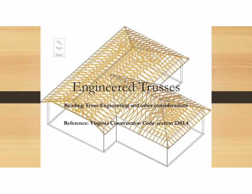
Engineered TrussesReading Truss Engineering and other considerations
Reference: Virginia Construction Code section 2303.4

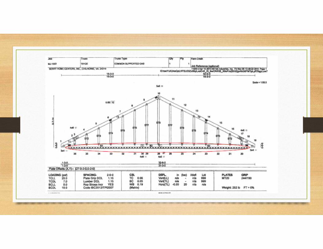
2303.4.1.1 Truss design drawings.The written, graphic and pictorial depiction of each individual truss shall be provided to the building official for approval prior to installation. Truss design drawings shall also be provided with the shipment of trusses delivered to the job site. Truss design drawings shall include, at a minimum, the information specified below:
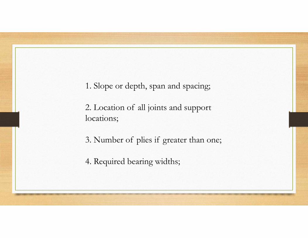
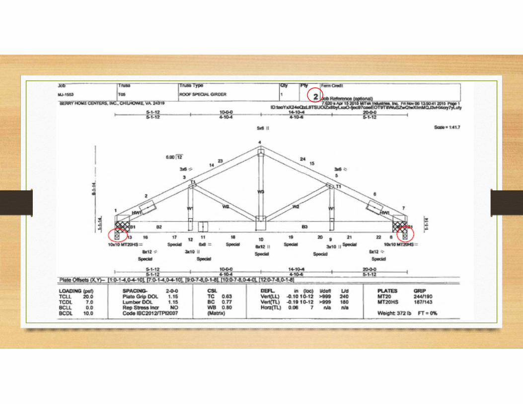
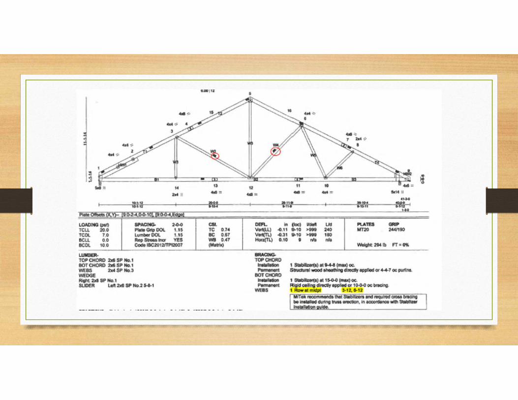
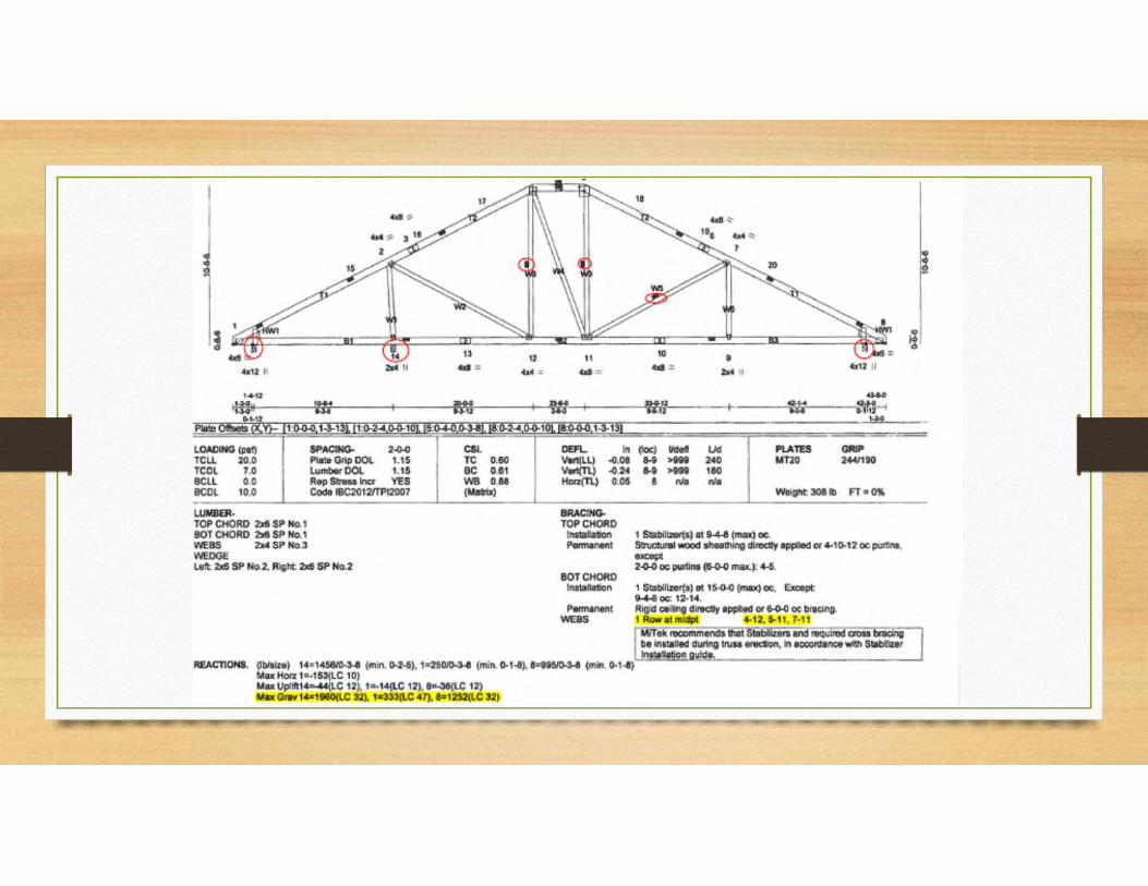
1. Slope or depth, span and spacing; 2. Location of all joints and support locations; 3. Number of plies if greater than one; 4. Required bearing widths;
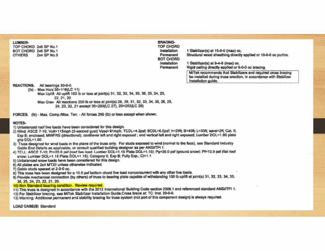
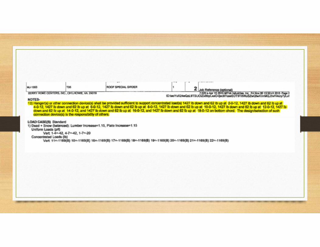
5. Design loads as applicable, including; 5.1. Top chord live load; 5.2. Top chord dead load; 5.3. Bottom chord live load; 5.4. Bottom chord dead load; 5.5. Additional loads and locations; and 5.6. Environmental design criteria and loads (wind, rain, snow, seismic, etc.).
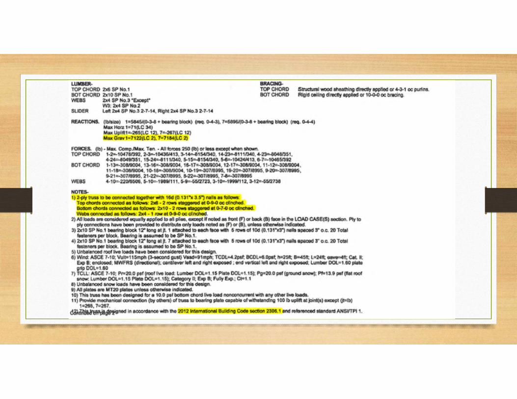
6. Other lateral loads, including drag strut loads; 7. Adjustments to wood member and metal connector plate design value for conditions of use; 8. Maximum reaction force and direction, including maximum uplift reaction forces where applicable; 9. Metal-connector-plate type, size and thickness or gage, and the dimensioned location of each metal connector plate except where symmetrically located relative to the joint interface; 10. Size, species and grade for each wood member;
11. Truss-to-truss connections and truss field assembly requirements; 12. Calculated span-to-deflection ratio and maximum vertical and horizontal deflection for live and total load as applicable; 13. Maximum axial tension and compression forces in the truss members; and 14. Required permanent individual truss member restraint location and the method and details of restraint/bracing to be used in accordance with Section 2303.4.1.2.
2303.4.1.2 Permanent individual truss member restraint. Where permanent restraint of truss members is required on the truss design drawings, it shall be accomplished by one of the following methods: 1. Permanent individual truss member restraint/bracing shall be installed using standard industry lateral restraint/bracing details in accordance with generally accepted engineering practice. Locations for lateral restraint shall be identified on the truss design drawing. 2. The trusses shall be designed so that the buckling of any individual truss member is resisted internally by the individual truss through suitable means (i.e., buckling reinforcement by T-reinforcement or L-reinforcement, proprietary reinforcement, etc.). The buckling reinforcement of individual members of the trusses shall be installed as shown on the truss design drawing or on supplemental truss member buckling reinforcement details provided by the truss designer. 3. A project-specific permanent individual truss member restraint/bracing design shall be permitted to be specified by any registered design professional.
2303.4.1.4.1 Truss design drawings. Where required by the registered design professional, the building official or the statutes of the jurisdiction in which the project is to be constructed, each individual truss design drawing shall bear the seal and signature of the truss designer. Exceptions:1. Where a cover sheet and truss index sheet are combined into a single sheet and attached to the set of truss design drawings, the single cover/truss index sheet is the only document required to be signed and sealed by the truss designer. 2. When a cover sheet and a truss index sheet are separately provided and attached to the set of truss design drawings, the cover sheet and the truss index sheet are the only documents required to be signed and sealed by the truss designer.
2303.4.2 Truss placement diagram.The truss manufacturer shall provide a truss placement diagram
that identifies the proposed location for each individually designated truss and references the corresponding truss design drawing. The truss placement diagram shall be provided as part of the truss submittal package, and with the shipment of trusses
delivered to the job site. Truss placement diagrams that serve only as a guide for installation and do not deviate from the
permit submittal drawings shall not be required to bear the seal or signature of the truss designer.
2303.4.3 Truss submittal package.The truss submittal package provided by the truss manufacturer shall consist of each individual truss design drawing, the truss placement diagram, the permanent individual truss member restraint/bracing method and details and any other structural details germane to the trusses; and, as applicable, the cover/truss index sheet. 2303.4.4 Anchorage.The design for the transfer of loads and anchorage of each truss to the supporting structure is the responsibility of the registered design professional.
2303.4.5 Alterations to trusses.Truss members and components shall not be cut, notched, drilled, spliced or otherwise altered in any way without written concurrence and approval of a registered design professional.Alterations resulting in the addition of loads to any member (e.g., HVAC equipment, piping, additional roofing or insulation, etc.) shall not be permitted without verification that the truss is capable of supporting such additional loading.

What do I do now?


The possibilities are endless with Engineered Roof Trusses
When executed properly
Next planned meeting:Erosion/Sediment ControlStormwater Management
Time and place to be determinedGo to:
http://www.washcova.com/administrative-directory/building-development/For updatesReminder:The Uniform Statewide Building Code is available online at:
http://codes.iccsafe.org/Virginia.html