Embed Size (px)
Citation preview
2009 Chevrolet Malibu | Malibu (VIN Z) Service Manual | Engine | Engine Controls and Fuel - 2.8L, 3.0L, 3.2L, or 3.6L | Specifications | Document ID: 1863475
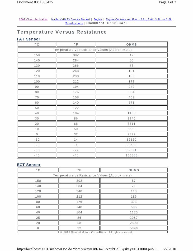
Temperature Versus Resistance
IAT Sensor
°C °F OHMS
Temperature vs Resistance Values (Approximate)
150 302 47
140 284 60
130 266 78
120 248 101
110 230 133
100 212 178
90 194 242
80 176 334
70 158 469
60 140 671
50 122 980
40 104 1465
30 86 2240
20 68 3511
10 50 5658
0 32 9399
-10 14 16120
-20 -4 28583
-30 -22 52594
-40 -40 100866
ECT Sensor
°C °F OHMS
Temperature vs Resistance Values (Approximate)
150 302 57
140 284 71
120 248 113
100 212 186
80 176 323
60 140 596
40 104 1175
25 86 2057
20 68 2500
0 32 5896 © 2010 General Motors Corporation. All rights reserved.
Page 1 of 2Document ID: 1863475
6/2/2010http://localhost:9001/si/showDoc.do?docSyskey=1863475&pubCellSyskey=161100&pubO...
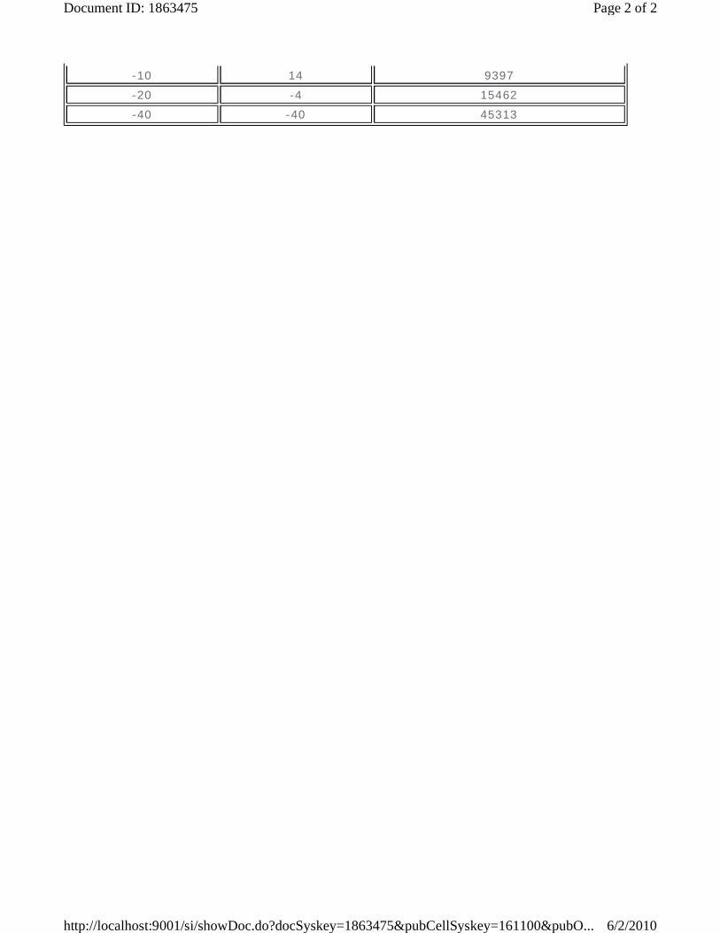
-10 14 9397
-20 -4 15462
-40 -40 45313
Page 2 of 2Document ID: 1863475
6/2/2010http://localhost:9001/si/showDoc.do?docSyskey=1863475&pubCellSyskey=161100&pubO...
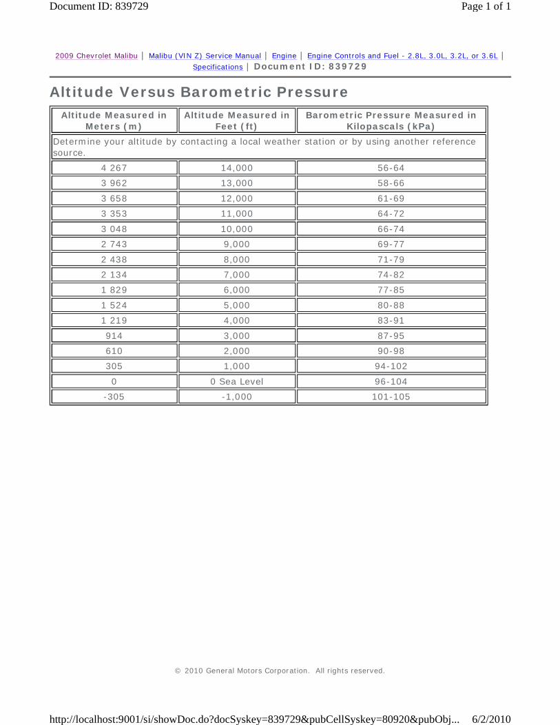
2009 Chevrolet Malibu | Malibu (VIN Z) Service Manual | Engine | Engine Controls and Fuel - 2.8L, 3.0L, 3.2L, or 3.6L | Specifications | Document ID: 839729
Altitude Versus Barometric Pressure
Altitude Measured in Meters (m)
Altitude Measured in Feet (ft)
Barometric Pressure Measured in Kilopascals (kPa)
Determine your altitude by contacting a local weather station or by using another reference source.
4 267 14,000 56-64
3 962 13,000 58-66
3 658 12,000 61-69
3 353 11,000 64-72
3 048 10,000 66-74
2 743 9,000 69-77
2 438 8,000 71-79
2 134 7,000 74-82
1 829 6,000 77-85
1 524 5,000 80-88
1 219 4,000 83-91
914 3,000 87-95
610 2,000 90-98
305 1,000 94-102
0 0 Sea Level 96-104
-305 -1,000 101-105
© 2010 General Motors Corporation. All rights reserved.
Page 1 of 1Document ID: 839729
6/2/2010http://localhost:9001/si/showDoc.do?docSyskey=839729&pubCellSyskey=80920&pubObj...
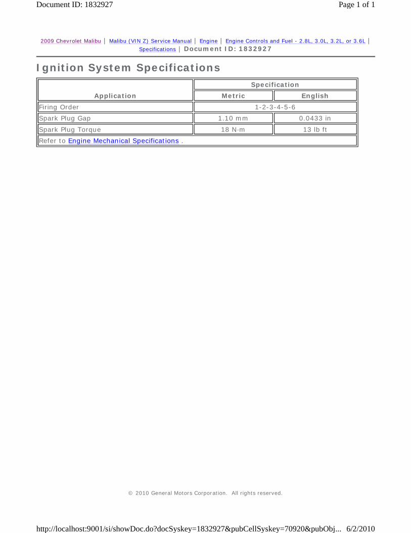
2009 Chevrolet Malibu | Malibu (VIN Z) Service Manual | Engine | Engine Controls and Fuel - 2.8L, 3.0L, 3.2L, or 3.6L | Specifications | Document ID: 1832927
Ignition System Specifications
Application
Specification
Metric English
Firing Order 1-2-3-4-5-6
Spark Plug Gap 1.10 mm 0.0433 in
Spark Plug Torque 18 N·m 13 lb ft
Refer to Engine Mechanical Specifications .
© 2010 General Motors Corporation. All rights reserved.
Page 1 of 1Document ID: 1832927
6/2/2010http://localhost:9001/si/showDoc.do?docSyskey=1832927&pubCellSyskey=70920&pubObj...
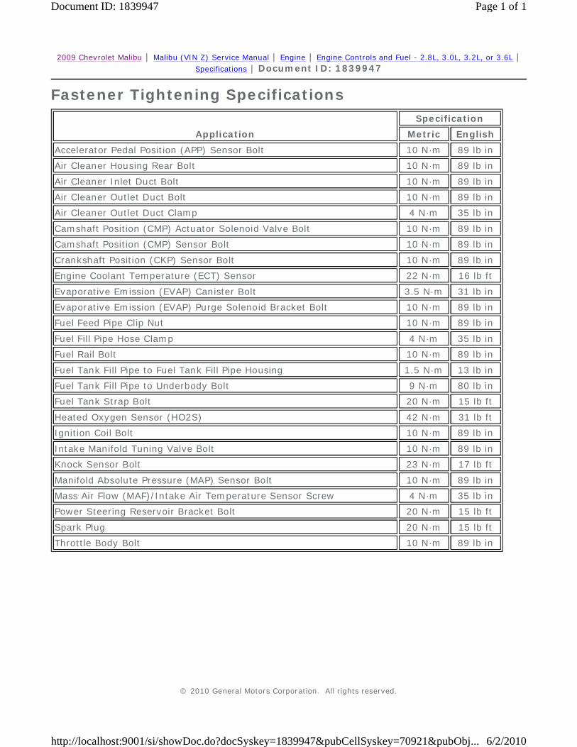
2009 Chevrolet Malibu | Malibu (VIN Z) Service Manual | Engine | Engine Controls and Fuel - 2.8L, 3.0L, 3.2L, or 3.6L | Specifications | Document ID: 1839947
Fastener Tightening Specifications
Application
Specification
Metric English
Accelerator Pedal Position (APP) Sensor Bolt 10 N·m 89 lb in
Air Cleaner Housing Rear Bolt 10 N·m 89 lb in
Air Cleaner Inlet Duct Bolt 10 N·m 89 lb in
Air Cleaner Outlet Duct Bolt 10 N·m 89 lb in
Air Cleaner Outlet Duct Clamp 4 N·m 35 lb in
Camshaft Position (CMP) Actuator Solenoid Valve Bolt 10 N·m 89 lb in
Camshaft Position (CMP) Sensor Bolt 10 N·m 89 lb in
Crankshaft Position (CKP) Sensor Bolt 10 N·m 89 lb in
Engine Coolant Temperature (ECT) Sensor 22 N·m 16 lb ft
Evaporative Emission (EVAP) Canister Bolt 3.5 N·m 31 lb in
Evaporative Emission (EVAP) Purge Solenoid Bracket Bolt 10 N·m 89 lb in
Fuel Feed Pipe Clip Nut 10 N·m 89 lb in
Fuel Fill Pipe Hose Clamp 4 N·m 35 lb in
Fuel Rail Bolt 10 N·m 89 lb in
Fuel Tank Fill Pipe to Fuel Tank Fill Pipe Housing 1.5 N·m 13 lb in
Fuel Tank Fill Pipe to Underbody Bolt 9 N·m 80 lb in
Fuel Tank Strap Bolt 20 N·m 15 lb ft
Heated Oxygen Sensor (HO2S) 42 N·m 31 lb ft
Ignition Coil Bolt 10 N·m 89 lb in
Intake Manifold Tuning Valve Bolt 10 N·m 89 lb in
Knock Sensor Bolt 23 N·m 17 lb ft
Manifold Absolute Pressure (MAP) Sensor Bolt 10 N·m 89 lb in
Mass Air Flow (MAF)/Intake Air Temperature Sensor Screw 4 N·m 35 lb in
Power Steering Reservoir Bracket Bolt 20 N·m 15 lb ft
Spark Plug 20 N·m 15 lb ft
Throttle Body Bolt 10 N·m 89 lb in
© 2010 General Motors Corporation. All rights reserved.
Page 1 of 1Document ID: 1839947
6/2/2010http://localhost:9001/si/showDoc.do?docSyskey=1839947&pubCellSyskey=70921&pubObj...
2009 Chevrolet Malibu | Malibu (VIN Z) Service Manual | Engine | Engine Controls and Fuel - 2.8L, 3.0L, 3.2L, or 3.6L | Schematic and Routing Diagrams | Document ID: 1237023
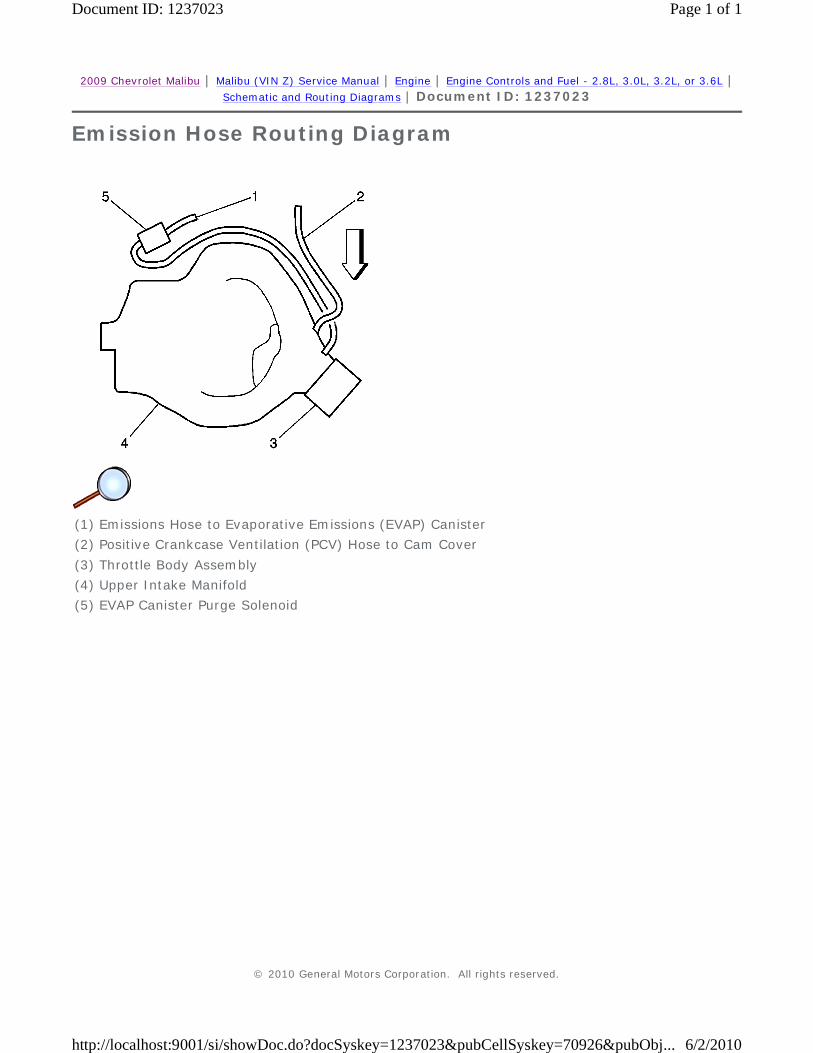
Emission Hose Routing Diagram
(1) Emissions Hose to Evaporative Emissions (EVAP) Canister
(2) Positive Crankcase Ventilation (PCV) Hose to Cam Cover
(3) Throttle Body Assembly
(4) Upper Intake Manifold
(5) EVAP Canister Purge Solenoid
© 2010 General Motors Corporation. All rights reserved.
Page 1 of 1Document ID: 1237023
6/2/2010http://localhost:9001/si/showDoc.do?docSyskey=1237023&pubCellSyskey=70926&pubObj...

2009 Chevrolet Malibu | Malibu (VIN Z) Service Manual | Engine | Engine Controls and Fuel - 2.8L, 3.0L, 3.2L, or 3.6L | Schematic and Routing Diagrams | Document ID: 1720335
Evaporative Emissions Hose Routing Diagram
(1) EVAP Canister Purge Solenoid Valve
(2) EVAP Canister
(3) Fluid Level Vent Valve
(4) Vapor Recirculation tube
(5) Fuel Fill Neck and Fill Cap
(6) Fuel Tank
(7) EVAP Canister Vent Valve
(8) Vent Hose/Pipe
(9) EVAP Vapor tube
(10) EVAP Purge tube
(11) EVAP Service Port or Service Access Connector
© 2010 General Motors Corporation. All rights reserved.
Page 1 of 1Document ID: 1720335
6/2/2010http://localhost:9001/si/showDoc.do?docSyskey=1720335&pubCellSyskey=70927&pubObj...
2009 Chevrolet Malibu | Malibu (VIN Z) Service Manual | Engine | Engine Controls and Fuel - 2.8L, 3.0L, 3.2L, or 3.6L | Repair Instructions | Document ID: 2068823
Crankshaft Position System Variation Learn Note: The Crankshaft Position (CKP) system variation learn procedure is also required when the following service procedures have been performed, regardless of whether DTC P0315 is set:
Note: The ECM monitors certain component signals to determine if all the conditions are met to continue with the CKP System Variation Learn Procedure. The scan tool only displays the condition that inhibits the procedure. The scan tool displays the signals of the following components:
1. Install a scan tool. 2. Monitor the ECM for DTCs with a scan tool. If other DTCs are set, except DTC P0315, refer to
Diagnostic Trouble Code (DTC) List - Vehicle for the applicable DTC that set. 3. With a scan tool, select the CKP System Variation Learn Procedure and perform the following:
4. The scan tool displays Learn Status: Learned this Ignition. If the scan tool indicates that DTC P0315 ran and passed, the CKP variation learn procedure is complete. If the scan tool indicates DTC P0315 failed or did not run, or another DTC is present, refer to Diagnostic Trouble Code (DTC) List - Vehicle and perform the appropriate diagnostic procedure.
5. Turn OFF the ignition for 30 seconds after the learn procedure is completed successfully in order to store the CKP system variation values in the ECM memory.
• An engine replacement
• A engine control module (ECM) replacement
• A crankshaft balancer replacement
• A crankshaft replacement
• A CKP sensor replacement
• Any engine repairs which disturb the crankshaft to CKP sensor relationship.
• CKP sensors activity--If there is a CKP sensor condition, refer to the applicable DTC that set.
• Camshaft position (CMP) signal activity--If there is a CMP signal condition, refer to the applicable DTC that set.
• Engine coolant temperature (ECT)--If the engine coolant temperature is not warm enough, idle the engine until the engine coolant temperature reaches the correct temperature.
3.1. Block drive wheels.
3.2. Set parking brake.
3.3. DO NOT apply brake pedal.
3.4. Cycle ignition from OFF to ON.
3.5. Apply and hold brake pedal for the duration of the procedure.
3.6. Start and idle engine.
3.7. Turn the air conditioning (A/C) OFF.
3.8. The vehicle must remain in Park or Neutral.
Note: While the learn procedure is in progress, release the throttle immediately when the engine starts to decelerate. The engine control is returned to the operator and the engine responds to throttle position after the learn procedure is complete.
3.9. Accelerate to wide open throttle (WOT) and release when the fuel cut-off occurs.
© 2010 General Motors Corporation. All rights reserved.
Page 1 of 1Document ID: 2068823
6/2/2010http://localhost:9001/si/showDoc.do?docSyskey=2068823&pubCellSyskey=161171&pubO...
2009 Chevrolet Malibu | Malibu (VIN Z) Service Manual | Engine | Engine Controls and Fuel - 2.8L, 3.0L, 3.2L, or 3.6L | Repair Instructions | Document ID: 2133069
Engine Control Module Replacement Caution:
Note: It is necessary to record the remaining engine oil life. If the replacement module is not programed with the remaining engine oil life, the engine oil life will default to 100 percent. If the replacement module is not programmed with the remaining engine oil life, the engine oil will need to be changed at 5 000 km (3,000 mi) from the last engine oil change.
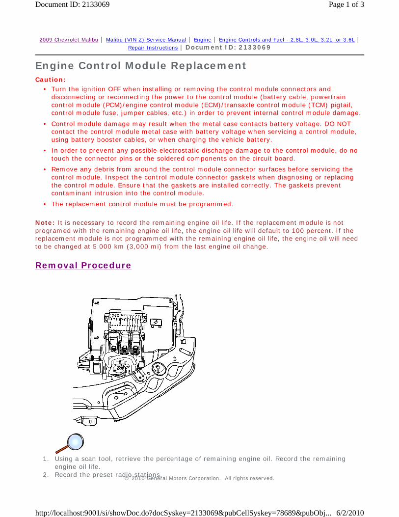
Removal Procedure
1. Using a scan tool, retrieve the percentage of remaining engine oil. Record the remaining
engine oil life. 2. Record the preset radio stations.
• Turn the ignition OFF when installing or removing the control module connectors and disconnecting or reconnecting the power to the control module (battery cable, powertrain control module (PCM)/engine control module (ECM)/transaxle control module (TCM) pigtail, control module fuse, jumper cables, etc.) in order to prevent internal control module damage.
• Control module damage may result when the metal case contacts battery voltage. DO NOT contact the control module metal case with battery voltage when servicing a control module, using battery booster cables, or when charging the vehicle battery.
• In order to prevent any possible electrostatic discharge damage to the control module, do no touch the connector pins or the soldered components on the circuit board.
• Remove any debris from around the control module connector surfaces before servicing the control module. Inspect the control module connector gaskets when diagnosing or replacing the control module. Ensure that the gaskets are installed correctly. The gaskets prevent contaminant intrusion into the control module.
• The replacement control module must be programmed.
© 2010 General Motors Corporation. All rights reserved.
Page 1 of 3Document ID: 2133069
6/2/2010http://localhost:9001/si/showDoc.do?docSyskey=2133069&pubCellSyskey=78689&pubObj...
3. Turn the ignition OFF. 4. Disconnect the negative battery cable. Refer to Battery Negative Cable Disconnection and
Connection. 5. Lift and gently pull the ECM up and out of the retainer on the battery tray.
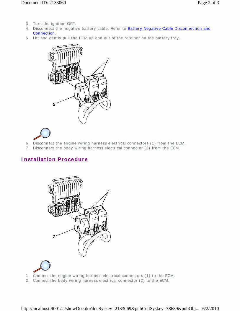
6. Disconnect the engine wiring harness electrical connectors (1) from the ECM. 7. Disconnect the body wiring harness electrical connector (2) from the ECM.
Installation Procedure
1. Connect the engine wiring harness electrical connectors (1) to the ECM. 2. Connect the body wiring harness electrical connector (2) to the ECM.
Page 2 of 3Document ID: 2133069
6/2/2010http://localhost:9001/si/showDoc.do?docSyskey=2133069&pubCellSyskey=78689&pubObj...
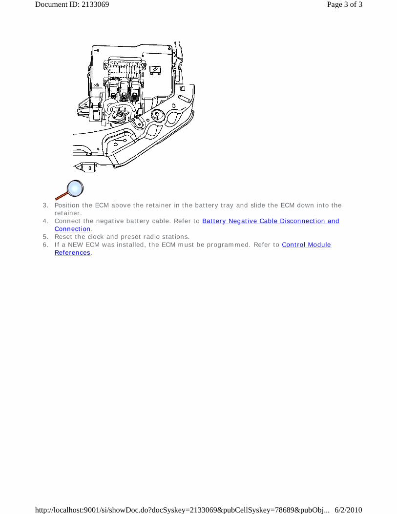
3. Position the ECM above the retainer in the battery tray and slide the ECM down into the
retainer. 4. Connect the negative battery cable. Refer to Battery Negative Cable Disconnection and
Connection. 5. Reset the clock and preset radio stations. 6. If a NEW ECM was installed, the ECM must be programmed. Refer to Control Module
References.
Page 3 of 3Document ID: 2133069
6/2/2010http://localhost:9001/si/showDoc.do?docSyskey=2133069&pubCellSyskey=78689&pubObj...
2009 Chevrolet Malibu | Malibu (VIN Z) Service Manual | Engine | Engine Controls and Fuel - 2.8L, 3.0L, 3.2L, or 3.6L | Repair Instructions | Document ID: 1906748
Throttle Learn
Description
The engine control module (ECM) learns the airflow through the throttle body to ensure the correct idle. The learned airflow values are stored within the ECM. These values are learned to adjust for production variation and will continuously learn during the life of the vehicle to compensate for reduced airflow due to coking. Anytime the throttle body airflow rate changes, for example due to cleaning or replacing, the values must be relearned.
A vehicle that had a heavily coked throttle body that has been cleaned or replaced may take several drive cycles to learn out the coking. To accelerate the process, the scan tool has the ability to reset all learned values back to zero. A new ECM will also have values set to zero.
The idle may be unstable or a DTC may set if the learned values do not match the actual airflow.
Conditions for Running the Throttle Learn Procedure
With Scan Tool - Reset Procedure
Without Scan Tool - Learn Procedure
Throttle Learn
With Scan Tool - Reset Procedure
1. Ignition ON, engine OFF, with a scan tool, perform the Idle Learn Reset in Module Setup. 2. Start the engine, monitor the TB Idle Airflow Compensation parameter. The TB Idle Airflow
• DTCs P0068, P0101, P0102, P0103, P0106, P0107, P0108, P0116, P0117, P0118, P0120, P0122, P0123, P0128, P0171, P0172, P0174, P0175, P0201, P0202, P0203, P0204, P0205, P0206, P0220, P0222, P0223, P0300, P0351, P0352, P0353, P0496, P0601, P0604, P0606, P060D, P0641, P0651, P1516, P2101, P2119, P2120, P2122, P2123, P2125, P2127, P2128, P2135, P2138, or P2176 are not set.
• Ignition ON, engine OFF.
• The vehicle speed sensor (VSS) is 0 km/h (0 mph).
• DTCs P0068, P0101, P0102, P0103, P0106, P0107, P0108, P0116, P0117, P0118, P0120, P0122, P0123, P0128, P0171, P0172, P0174, P0175, P0201, P0202, P0203, P0204, P0205, P0206, P0220, P0222, P0223, P0300, P0351, P0352, P0353, P0496, P0601, P0604, P0606, P060D, P0641, P0651, P1516, P2101, P2119, P2120, P2122, P2123, P2125, P2127, P2128, P2135, P2138, or P2176 are not set.
• The engine speed is between 450-4,000 RPM.
• The manifold absolute pressure (MAP) is greater than 5 kPa.
• The mass air flow (MAF) is greater than 2 g/s.
• The ignition 1 voltage is greater than 10 volts.
© 2010 General Motors Corporation. All rights reserved.
Page 1 of 2Document ID: 1906748
6/2/2010http://localhost:9001/si/showDoc.do?docSyskey=1906748&pubCellSyskey=161402&pubO...

Compensation value should equal 0 percent and the engine should be idling at a normal idle speed.
3. Clear the DTCs and return to the diagnostic that referred you here.
Without Scan Tool - Learn Procedure
Important: Do NOT perform this procedure if DTCs are set. Refer to Diagnostic Trouble Code (DTC) List - Vehicle.
1. Start and idle the engine in PARK for 3 minutes. 2. With a scan tool, monitor desired and actual RPM. 3. The ECM will start to learn the new idle cells and Desired RPM should start to decrease. 4. Ignition OFF for 60 seconds. 5. Start and idle the engine in PARK for 3 minutes. 6. After the 3 minute run time the engine should be idling normal.
Important: During the drive cycle the check engine light may come on with idle speed DTCs. If idle speed codes are set, clear codes so the ECM can continue to learn.
7. After the drive cycle, the engine should be idling normally.
8. Once the engine speed has returned to normal, clear DTCs and return to the diagnostic that referred you here.
⇒ If the engine idle speed has not been learned the vehicle will need to be driven at speeds above 70 km/h (44 mph) with several decelerations and extended idles.
⇒ If the engine idle speed has not been learned, turn OFF the ignition for 60 seconds and repeat step 6.
Page 2 of 2Document ID: 1906748
6/2/2010http://localhost:9001/si/showDoc.do?docSyskey=1906748&pubCellSyskey=161402&pubO...

2009 Chevrolet Malibu | Malibu (VIN Z) Service Manual | Engine | Engine Controls and Fuel - 2.8L, 3.0L, 3.2L, or 3.6L | Repair Instructions | Document ID: 2133071
Engine Coolant Temperature Sensor Replacement
Removal Procedure
1. Disconnect the engine wiring harness electrical connector (1) from the engine coolant
temperature (ECT) sensor.
2. Remove the ECT sensor.
Installation Procedure © 2010 General Motors Corporation. All rights reserved.
Page 1 of 2Document ID: 2133071
6/2/2010http://localhost:9001/si/showDoc.do?docSyskey=2133071&pubCellSyskey=78690&pubObj...
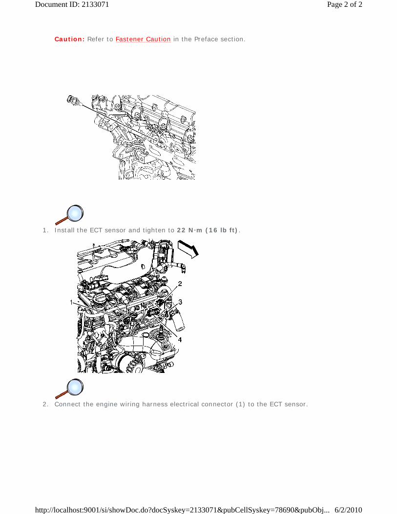
Caution: Refer to Fastener Caution in the Preface section.
1. Install the ECT sensor and tighten to 22 N·m (16 lb ft).
2. Connect the engine wiring harness electrical connector (1) to the ECT sensor.
Page 2 of 2Document ID: 2133071
6/2/2010http://localhost:9001/si/showDoc.do?docSyskey=2133071&pubCellSyskey=78690&pubObj...
2009 Chevrolet Malibu | Malibu (VIN Z) Service Manual | Engine | Engine Controls and Fuel - 2.8L, 3.0L, 3.2L, or 3.6L | Repair Instructions | Document ID: 2133074
Mass Airflow Sensor with Intake Air Temperature Sensor Replacement
Removal Procedure
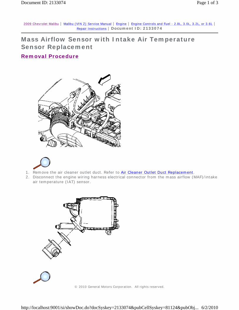
1. Remove the air cleaner outlet duct. Refer to Air Cleaner Outlet Duct Replacement. 2. Disconnect the engine wiring harness electrical connector from the mass airflow (MAF)/intake
air temperature (IAT) sensor.
© 2010 General Motors Corporation. All rights reserved.
Page 1 of 3Document ID: 2133074
6/2/2010http://localhost:9001/si/showDoc.do?docSyskey=2133074&pubCellSyskey=81124&pubObj...

3. Remove the MAF/IAT sensor screws. 4. Remove the MAF/IAT sensor. 5. Remove and discard the MAF/IAT sensor seal.
Installation Procedure
1. Install a NEW MAF/IAT sensor seal. 2. Install the MAF/IAT sensor.
Caution: Refer to Fastener Caution in the Preface section.
3. Install the MAF/IAT sensor screws and tighten to 4 N·m (35 lb in).
Page 2 of 3Document ID: 2133074
6/2/2010http://localhost:9001/si/showDoc.do?docSyskey=2133074&pubCellSyskey=81124&pubObj...
4. Connect the engine wiring harness electrical connector to the MAF/IAT sensor. 5. Install the air cleaner outlet duct. Refer to Air Cleaner Outlet Duct Replacement.
Page 3 of 3Document ID: 2133074
6/2/2010http://localhost:9001/si/showDoc.do?docSyskey=2133074&pubCellSyskey=81124&pubObj...
2009 Chevrolet Malibu | Malibu (VIN Z) Service Manual | Engine | Engine Controls and Fuel - 2.8L, 3.0L, 3.2L, or 3.6L | Repair Instructions | Document ID: 2133079
Manifold Absolute Pressure Sensor Replacement
Removal Procedure
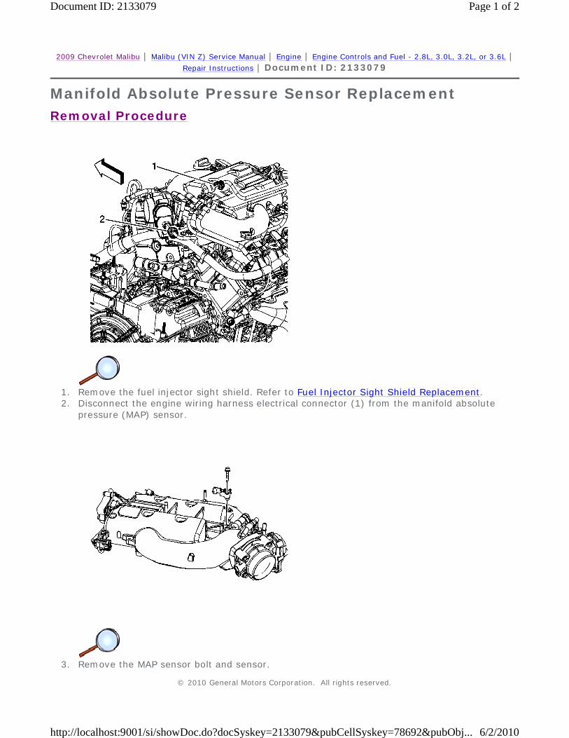
1. Remove the fuel injector sight shield. Refer to Fuel Injector Sight Shield Replacement. 2. Disconnect the engine wiring harness electrical connector (1) from the manifold absolute
pressure (MAP) sensor.
3. Remove the MAP sensor bolt and sensor.
© 2010 General Motors Corporation. All rights reserved.
Page 1 of 2Document ID: 2133079
6/2/2010http://localhost:9001/si/showDoc.do?docSyskey=2133079&pubCellSyskey=78692&pubObj...
Installation Procedure
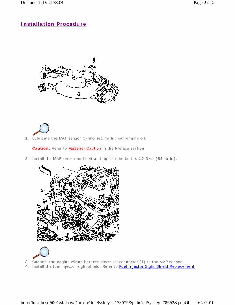
1. Lubricate the MAP sensor O-ring seal with clean engine oil.
Caution: Refer to Fastener Caution in the Preface section.
2. Install the MAP sensor and bolt and tighten the bolt to 10 N·m (89 lb in).
3. Connect the engine wiring harness electrical connector (1) to the MAP sensor. 4. Install the fuel injector sight shield. Refer to Fuel Injector Sight Shield Replacement.
Page 2 of 2Document ID: 2133079
6/2/2010http://localhost:9001/si/showDoc.do?docSyskey=2133079&pubCellSyskey=78692&pubObj...
2009 Chevrolet Malibu | Malibu (VIN Z) Service Manual | Engine | Engine Controls and Fuel - 2.8L, 3.0L, 3.2L, or 3.6L | Repair Instructions | Document ID: 2133081
Heated Oxygen Sensor Replacement - Bank 1 Sensor 1
Removal Procedure
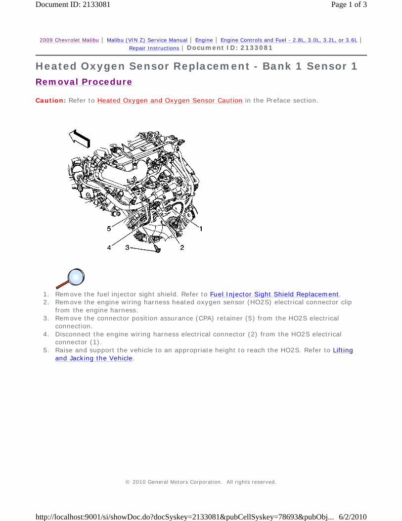
Caution: Refer to Heated Oxygen and Oxygen Sensor Caution in the Preface section.
1. Remove the fuel injector sight shield. Refer to Fuel Injector Sight Shield Replacement. 2. Remove the engine wiring harness heated oxygen sensor (HO2S) electrical connector clip
from the engine harness. 3. Remove the connector position assurance (CPA) retainer (5) from the HO2S electrical
connection. 4. Disconnect the engine wiring harness electrical connector (2) from the HO2S electrical
connector (1). 5. Raise and support the vehicle to an appropriate height to reach the HO2S. Refer to Lifting
and Jacking the Vehicle.
© 2010 General Motors Corporation. All rights reserved.
Page 1 of 3Document ID: 2133081
6/2/2010http://localhost:9001/si/showDoc.do?docSyskey=2133081&pubCellSyskey=78693&pubObj...
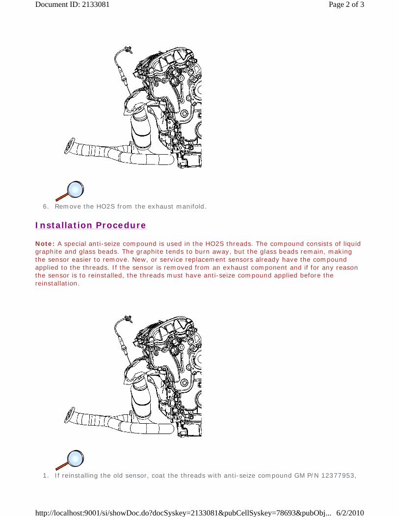
6. Remove the HO2S from the exhaust manifold.
Installation Procedure
Note: A special anti-seize compound is used in the HO2S threads. The compound consists of liquid graphite and glass beads. The graphite tends to burn away, but the glass beads remain, making the sensor easier to remove. New, or service replacement sensors already have the compound applied to the threads. If the sensor is removed from an exhaust component and if for any reason the sensor is to reinstalled, the threads must have anti-seize compound applied before the reinstallation.
1. If reinstalling the old sensor, coat the threads with anti-seize compound GM P/N 12377953,
Page 2 of 3Document ID: 2133081
6/2/2010http://localhost:9001/si/showDoc.do?docSyskey=2133081&pubCellSyskey=78693&pubObj...
or equivalent.
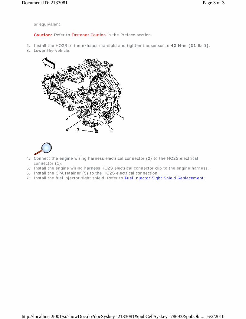
Caution: Refer to Fastener Caution in the Preface section.
2. Install the HO2S to the exhaust manifold and tighten the sensor to 42 N·m (31 lb ft). 3. Lower the vehicle.
4. Connect the engine wiring harness electrical connector (2) to the HO2S electrical
connector (1). 5. Install the engine wiring harness HO2S electrical connector clip to the engine harness. 6. Install the CPA retainer (5) to the HO2S electrical connection. 7. Install the fuel injector sight shield. Refer to Fuel Injector Sight Shield Replacement.
Page 3 of 3Document ID: 2133081
6/2/2010http://localhost:9001/si/showDoc.do?docSyskey=2133081&pubCellSyskey=78693&pubObj...
2009 Chevrolet Malibu | Malibu (VIN Z) Service Manual | Engine | Engine Controls and Fuel - 2.8L, 3.0L, 3.2L, or 3.6L | Repair Instructions | Document ID: 2133084
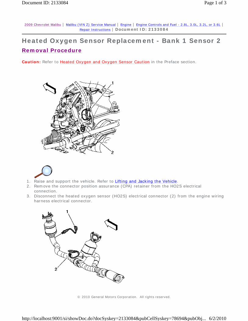
Heated Oxygen Sensor Replacement - Bank 1 Sensor 2
Removal Procedure
Caution: Refer to Heated Oxygen and Oxygen Sensor Caution in the Preface section.
1. Raise and support the vehicle. Refer to Lifting and Jacking the Vehicle. 2. Remove the connector position assurance (CPA) retainer from the HO2S electrical
connection. 3. Disconnect the heated oxygen sensor (HO2S) electrical connector (2) from the engine wiring
harness electrical connector.
© 2010 General Motors Corporation. All rights reserved.
Page 1 of 3Document ID: 2133084
6/2/2010http://localhost:9001/si/showDoc.do?docSyskey=2133084&pubCellSyskey=78694&pubObj...

4. Remove the bank 1 sensor 2 HO2S (2) from the catalytic converter.
Installation Procedure
Note: A special anti-seize compound is used in the HO2S threads. The compound consists of liquid graphite and glass beads. The graphite tends to burn away, but the glass beads remain, making the sensor easier to remove. New, or service replacement sensors already have the compound applied to the threads. If the sensor is removed from an exhaust component and if for any reason the sensor is to reinstalled, the threads must have anti-seize compound applied before the reinstallation.
1. If reinstalling the old sensor, coat the threads with anti-seize compound GM P/N 12377953,
or equivalent.
Caution: Refer to Fastener Caution in the Preface section.
2. Install the bank 1 sensor 2 HO2S (2) to the catalytic converter and tighten the sensor to 42 N·m (31 lb ft).
Page 2 of 3Document ID: 2133084
6/2/2010http://localhost:9001/si/showDoc.do?docSyskey=2133084&pubCellSyskey=78694&pubObj...
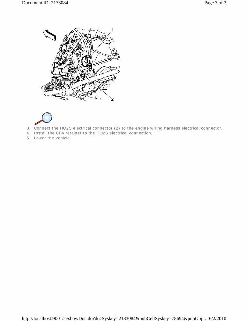
3. Connect the HO2S electrical connector (2) to the engine wiring harness electrical connector. 4. Install the CPA retainer to the HO2S electrical connection. 5. Lower the vehicle.
Page 3 of 3Document ID: 2133084
6/2/2010http://localhost:9001/si/showDoc.do?docSyskey=2133084&pubCellSyskey=78694&pubObj...
2009 Chevrolet Malibu | Malibu (VIN Z) Service Manual | Engine | Engine Controls and Fuel - 2.8L, 3.0L, 3.2L, or 3.6L | Repair Instructions | Document ID: 2133091
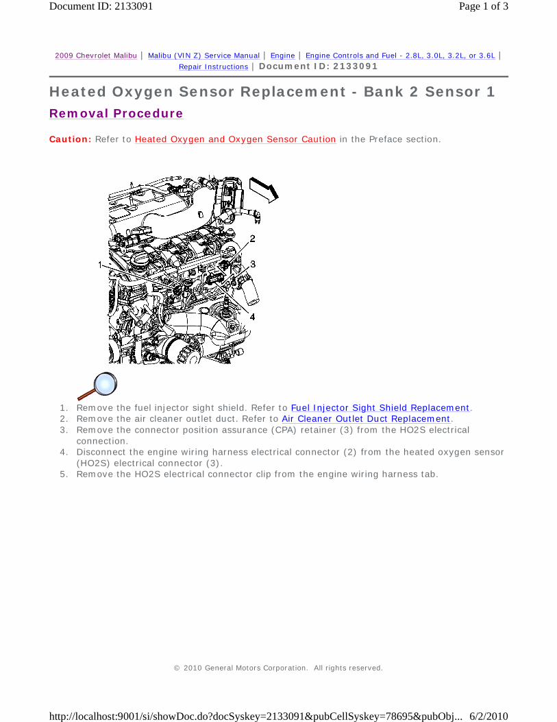
Heated Oxygen Sensor Replacement - Bank 2 Sensor 1
Removal Procedure
Caution: Refer to Heated Oxygen and Oxygen Sensor Caution in the Preface section.
1. Remove the fuel injector sight shield. Refer to Fuel Injector Sight Shield Replacement. 2. Remove the air cleaner outlet duct. Refer to Air Cleaner Outlet Duct Replacement. 3. Remove the connector position assurance (CPA) retainer (3) from the HO2S electrical
connection. 4. Disconnect the engine wiring harness electrical connector (2) from the heated oxygen sensor
(HO2S) electrical connector (3). 5. Remove the HO2S electrical connector clip from the engine wiring harness tab.
© 2010 General Motors Corporation. All rights reserved.
Page 1 of 3Document ID: 2133091
6/2/2010http://localhost:9001/si/showDoc.do?docSyskey=2133091&pubCellSyskey=78695&pubObj...
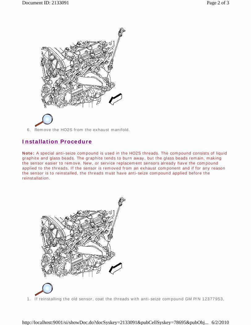
6. Remove the HO2S from the exhaust manifold.
Installation Procedure
Note: A special anti-seize compound is used in the HO2S threads. The compound consists of liquid graphite and glass beads. The graphite tends to burn away, but the glass beads remain, making the sensor easier to remove. New, or service replacement sensors already have the compound applied to the threads. If the sensor is removed from an exhaust component and if for any reason the sensor is to reinstalled, the threads must have anti-seize compound applied before the reinstallation.
1. If reinstalling the old sensor, coat the threads with anti-seize compound GM P/N 12377953,
Page 2 of 3Document ID: 2133091
6/2/2010http://localhost:9001/si/showDoc.do?docSyskey=2133091&pubCellSyskey=78695&pubObj...
or equivalent.
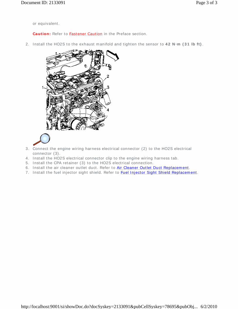
Caution: Refer to Fastener Caution in the Preface section.
2. Install the HO2S to the exhaust manifold and tighten the sensor to 42 N·m (31 lb ft).
3. Connect the engine wiring harness electrical connector (2) to the HO2S electrical
connector (3). 4. Install the HO2S electrical connector clip to the engine wiring harness tab. 5. Install the CPA retainer (3) to the HO2S electrical connection. 6. Install the air cleaner outlet duct. Refer to Air Cleaner Outlet Duct Replacement. 7. Install the fuel injector sight shield. Refer to Fuel Injector Sight Shield Replacement.
Page 3 of 3Document ID: 2133091
6/2/2010http://localhost:9001/si/showDoc.do?docSyskey=2133091&pubCellSyskey=78695&pubObj...

2009 Chevrolet Malibu | Malibu (VIN Z) Service Manual | Engine | Engine Controls and Fuel - 2.8L, 3.0L, 3.2L, or 3.6L | Repair Instructions | Document ID: 2133097
Heated Oxygen Sensor Replacement - Bank 2 Sensor 2
Removal Procedure
Caution: Refer to Heated Oxygen and Oxygen Sensor Caution in the Preface section.
1. Raise and support the vehicle. Refer to Lifting and Jacking the Vehicle. 2. Remove the connector position assurance (CPA) retainer (4) from the HO2S electrical
connection. 3. Disconnect the heated oxygen sensor (HO2S) electrical connector (3) from the engine wiring
harness electrical connector (2).
© 2010 General Motors Corporation. All rights reserved.
Page 1 of 3Document ID: 2133097
6/2/2010http://localhost:9001/si/showDoc.do?docSyskey=2133097&pubCellSyskey=78696&pubObj...
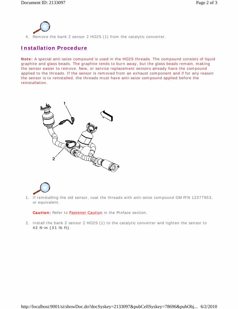
4. Remove the bank 2 sensor 2 HO2S (1) from the catalytic converter.
Installation Procedure
Note: A special anti-seize compound is used in the HO2S threads. The compound consists of liquid graphite and glass beads. The graphite tends to burn away, but the glass beads remain, making the sensor easier to remove. New, or service replacement sensors already have the compound applied to the threads. If the sensor is removed from an exhaust component and if for any reason the sensor is to reinstalled, the threads must have anti-seize compound applied before the reinstallation.
1. If reinstalling the old sensor, coat the threads with anti-seize compound GM P/N 12377953,
or equivalent.
Caution: Refer to Fastener Caution in the Preface section.
2. Install the bank 2 sensor 2 HO2S (1) to the catalytic converter and tighten the sensor to 42 N·m (31 lb ft).
Page 2 of 3Document ID: 2133097
6/2/2010http://localhost:9001/si/showDoc.do?docSyskey=2133097&pubCellSyskey=78696&pubObj...
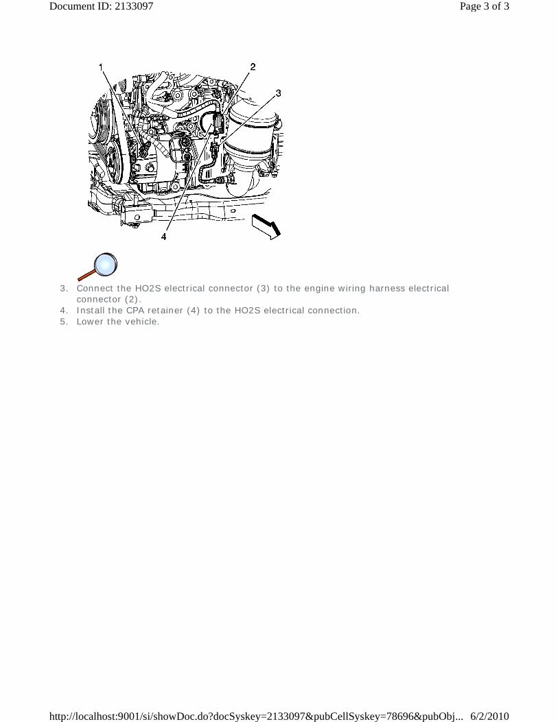
3. Connect the HO2S electrical connector (3) to the engine wiring harness electrical
connector (2). 4. Install the CPA retainer (4) to the HO2S electrical connection. 5. Lower the vehicle.
Page 3 of 3Document ID: 2133097
6/2/2010http://localhost:9001/si/showDoc.do?docSyskey=2133097&pubCellSyskey=78696&pubObj...
2009 Chevrolet Malibu | Malibu (VIN Z) Service Manual | Engine | Engine Controls and Fuel - 2.8L, 3.0L, 3.2L, or 3.6L | Repair Instructions | Document ID: 2133103
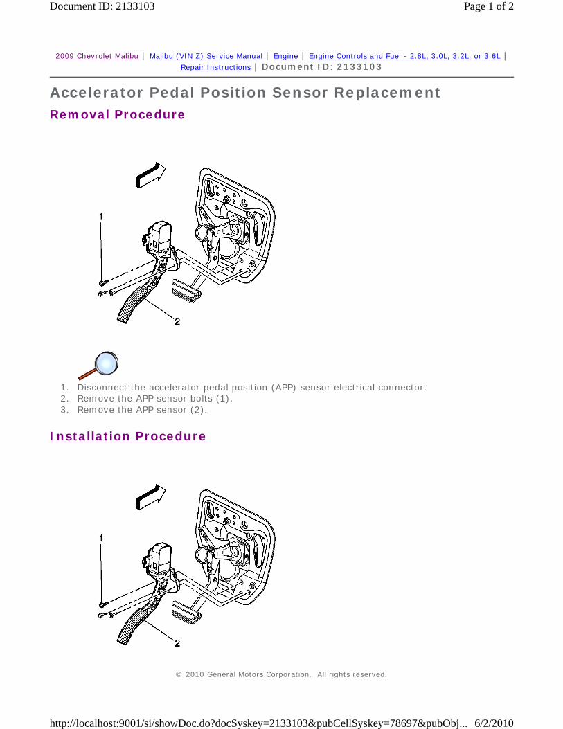
Accelerator Pedal Position Sensor Replacement
Removal Procedure
1. Disconnect the accelerator pedal position (APP) sensor electrical connector. 2. Remove the APP sensor bolts (1). 3. Remove the APP sensor (2).
Installation Procedure
© 2010 General Motors Corporation. All rights reserved.
Page 1 of 2Document ID: 2133103
6/2/2010http://localhost:9001/si/showDoc.do?docSyskey=2133103&pubCellSyskey=78697&pubObj...

1. Install the APP sensor (2).
Caution: Refer to Fastener Caution in the Preface section.
2. Install the APP bolts (1) and tighten to 10 N·m (89 lb in). 3. Connect the APP sensor electrical connector. 4. Confirm that the APP sensor connector locking clip is fully secured.
Page 2 of 2Document ID: 2133103
6/2/2010http://localhost:9001/si/showDoc.do?docSyskey=2133103&pubCellSyskey=78697&pubObj...

2009 Chevrolet Malibu | Malibu (VIN Z) Service Manual | Engine | Engine Controls and Fuel - 2.8L, 3.0L, 3.2L, or 3.6L | Repair Instructions | Document ID: 2133110
Throttle Body Assembly Replacement
Removal Procedure
1. Remove the air cleaner outlet duct. Refer to Air Cleaner Outlet Duct Replacement. 2. Disconnect the engine wiring harness electrical connector (2) from the electronic throttle
control (ETC).
3. Remove the throttle body bolts. 4. Remove the throttle body and gasket. Discard the gasket.
© 2010 General Motors Corporation. All rights reserved.
Page 1 of 2Document ID: 2133110
6/2/2010http://localhost:9001/si/showDoc.do?docSyskey=2133110&pubCellSyskey=78698&pubObj...
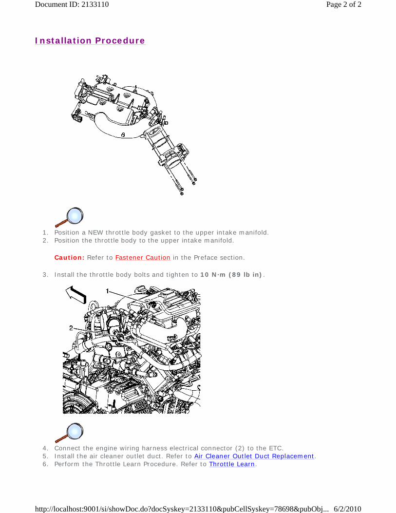
Installation Procedure
1. Position a NEW throttle body gasket to the upper intake manifold. 2. Position the throttle body to the upper intake manifold.
Caution: Refer to Fastener Caution in the Preface section.
3. Install the throttle body bolts and tighten to 10 N·m (89 lb in).
4. Connect the engine wiring harness electrical connector (2) to the ETC. 5. Install the air cleaner outlet duct. Refer to Air Cleaner Outlet Duct Replacement. 6. Perform the Throttle Learn Procedure. Refer to Throttle Learn.
Page 2 of 2Document ID: 2133110
6/2/2010http://localhost:9001/si/showDoc.do?docSyskey=2133110&pubCellSyskey=78698&pubObj...
2009 Chevrolet Malibu | Malibu (VIN Z) Service Manual | Engine | Engine Controls and Fuel - 2.8L, 3.0L, 3.2L, or 3.6L | Repair Instructions | Document ID: 2074113
Throttle Body Inspection and Cleaning Note: Over extended time and mileage, deposits may accumulate on the back of the throttle valve plate. The source of the deposit is exhaust gas recirculation (EGR) gas. Typically these deposits pose no problem. Occasionally the deposit may accumulate to a point where perceived pedal effort or throttle valve movement is effected. This procedure should not be performed on vehicles with mileage under 80 450 km (50,000 mi).
1. Remove the air cleaner outlet duct. Refer to Air Cleaner Outlet Duct Replacement.
Warning: Turn OFF the ignition before inserting fingers into the throttle bore. Unexpected movement of the throttle blade could cause personal injury.
Caution: Do not insert any tools into the throttle body bore in order to avoid damage to the throttle valve plate.
2. Inspect the throttle body bore and the throttle valve plate for deposits. You will need to open the throttle valve in order to inspect all surfaces.
Caution: Do not use any solvent that contains Methyl Ethyl Ketone (MEK). This solvent may damage fuel system components.
3. Clean the throttle body bore and the throttle valve plate using a clean shop towel with GM top engine cleaner, GM P/N 1052626 (Canadian P/N 993026) or AC-Delco Carburetor Tune-Up Conditioner, P/N X66-P, or an equivalent product.
4. Install the air cleaner outlet duct. Refer to Air Cleaner Outlet Duct Replacement.
© 2010 General Motors Corporation. All rights reserved.
Page 1 of 1Document ID: 2074113
6/2/2010http://localhost:9001/si/showDoc.do?docSyskey=2074113&pubCellSyskey=78699&pubObj...
2009 Chevrolet Malibu | Malibu (VIN Z) Service Manual | Engine | Engine Controls and Fuel - 2.8L, 3.0L, 3.2L, or 3.6L | Repair Instructions | Document ID: 2133193
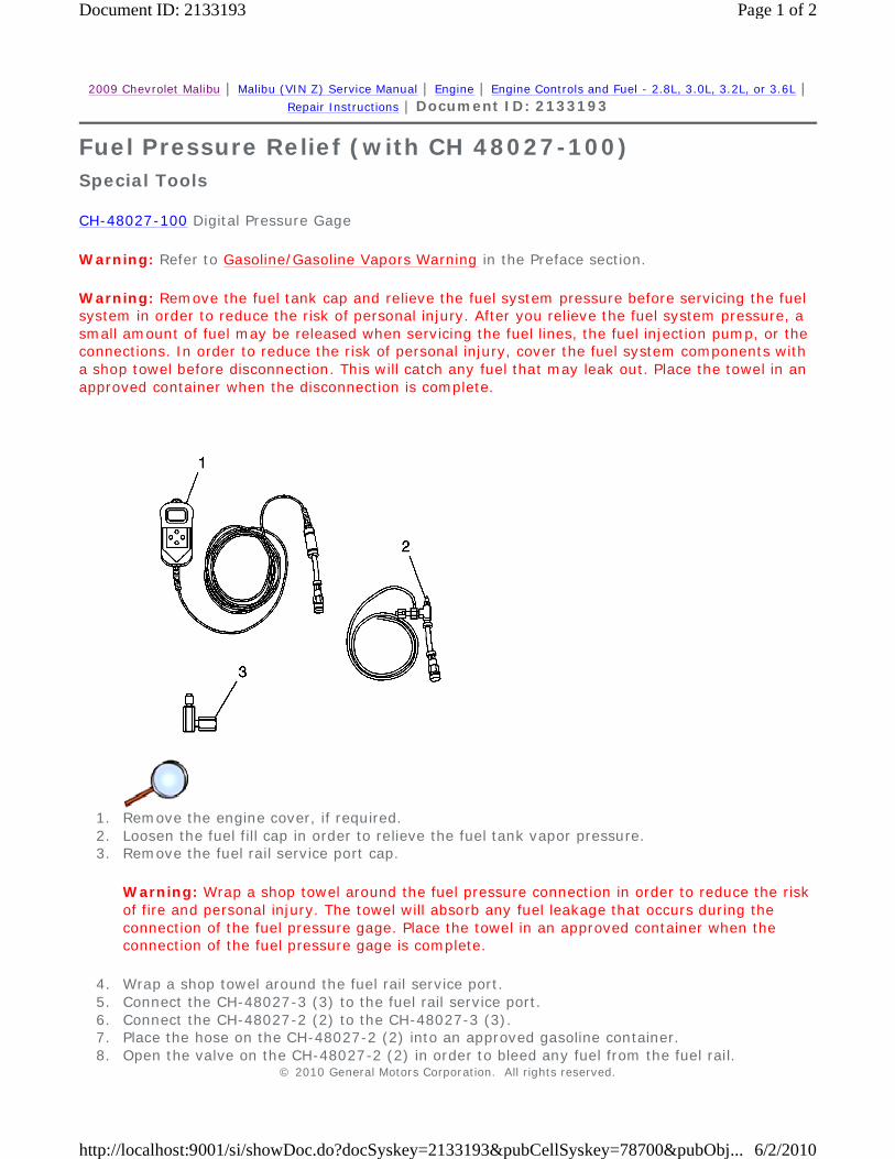
Fuel Pressure Relief (with CH 48027-100)
Special Tools
CH-48027-100 Digital Pressure Gage
Warning: Refer to Gasoline/Gasoline Vapors Warning in the Preface section.
Warning: Remove the fuel tank cap and relieve the fuel system pressure before servicing the fuel system in order to reduce the risk of personal injury. After you relieve the fuel system pressure, a small amount of fuel may be released when servicing the fuel lines, the fuel injection pump, or the connections. In order to reduce the risk of personal injury, cover the fuel system components with a shop towel before disconnection. This will catch any fuel that may leak out. Place the towel in an approved container when the disconnection is complete.
1. Remove the engine cover, if required. 2. Loosen the fuel fill cap in order to relieve the fuel tank vapor pressure. 3. Remove the fuel rail service port cap.
Warning: Wrap a shop towel around the fuel pressure connection in order to reduce the risk of fire and personal injury. The towel will absorb any fuel leakage that occurs during the connection of the fuel pressure gage. Place the towel in an approved container when the connection of the fuel pressure gage is complete.
4. Wrap a shop towel around the fuel rail service port. 5. Connect the CH-48027-3 (3) to the fuel rail service port. 6. Connect the CH-48027-2 (2) to the CH-48027-3 (3). 7. Place the hose on the CH-48027-2 (2) into an approved gasoline container. 8. Open the valve on the CH-48027-2 (2) in order to bleed any fuel from the fuel rail.
© 2010 General Motors Corporation. All rights reserved.
Page 1 of 2Document ID: 2133193
6/2/2010http://localhost:9001/si/showDoc.do?docSyskey=2133193&pubCellSyskey=78700&pubObj...
9. Close the valve on the CH-48027-2 (2). 10. Remove the hose on the CH-48027-2 (2) from the approved gasoline container.
Caution: Clean all of the following areas before performing any disconnections in order to avoid possible contamination in the system:
Note: If relieving the fuel pressure for the fuel pressure gage installation and removal, it is NOT necessary to proceed with the following steps.
11. Disconnect the CH-48027-2 (2) from the CH-48027-3 (3). 12. Disconnect the CH-48027-3 (3) from the fuel rail service port. 13. Remove the shop towel from around the fuel rail service port, and place in an approved
gasoline container. 14. Install the fuel rail service port cap. 15. Install the engine cover, if required. 16. Tighten the fuel fill cap.
• The fuel pipe connections
• The hose connections
• The areas surrounding the connections
Page 2 of 2Document ID: 2133193
6/2/2010http://localhost:9001/si/showDoc.do?docSyskey=2133193&pubCellSyskey=78700&pubObj...

2009 Chevrolet Malibu | Malibu (VIN Z) Service Manual | Engine | Engine Controls and Fuel - 2.8L, 3.0L, 3.2L, or 3.6L | Repair Instructions | Document ID: 2133195
Fuel Pressure Relief (w/o CH 48027-100) Warning: Refer to Gasoline/Gasoline Vapors Warning in the Preface section.
Warning: Remove the fuel tank cap and relieve the fuel system pressure before servicing the fuel system in order to reduce the risk of personal injury. After you relieve the fuel system pressure, a small amount of fuel may be released when servicing the fuel lines, the fuel injection pump, or the connections. In order to reduce the risk of personal injury, cover the fuel system components with a shop towel before disconnection. This will catch any fuel that may leak out. Place the towel in an approved container when the disconnection is complete.
1. Loosen the fuel fill cap in order to relieve the fuel tank vapor pressure. 2. Remove the engine cover, if required. 3. Remove the fuel rail service port cap. 4. Wrap a shop towel around the fuel rail service port and using a small flat bladed tool, depress
(open) the fuel rail test port valve. 5. Remove the shop towel from around the fuel rail service port, and place in an approved
gasoline container. 6. Install the fuel rail service port cap. 7. Install the engine cover, if required. 8. Tighten the fuel fill cap.
© 2010 General Motors Corporation. All rights reserved.
Page 1 of 1Document ID: 2133195
6/2/2010http://localhost:9001/si/showDoc.do?docSyskey=2133195&pubCellSyskey=78700&pubObj...

2009 Chevrolet Malibu | Malibu (VIN Z) Service Manual | Engine | Engine Controls and Fuel - 2.8L, 3.0L, 3.2L, or 3.6L | Repair Instructions | Document ID: 2133196
Fuel Pressure Gage Installation and Removal
Special Tools
CH-48027-100 Digital Pressure Gage
Installation Procedure
Warning: Refer to Gasoline/Gasoline Vapors Warning in the Preface section.
Warning: Remove the fuel tank cap and relieve the fuel system pressure before servicing the fuel system in order to reduce the risk of personal injury. After you relieve the fuel system pressure, a small amount of fuel may be released when servicing the fuel lines, the fuel injection pump, or the connections. In order to reduce the risk of personal injury, cover the fuel system components with a shop towel before disconnection. This will catch any fuel that may leak out. Place the towel in an approved container when the disconnection is complete.
1. Relieve the fuel system pressure. Refer to Fuel Pressure Relief. 2. Connect the CH-48027-1 (1) to the CH-48027-2 (2). 3. Remove the shop towel from around the fuel rail service port, and place in an approved
gasoline container. 4. Perform any tests and/or diagnostics as needed. For the proper usage of the CH-48027-100 ,
refer to the manufacture's directions.
Removal Procedure
© 2010 General Motors Corporation. All rights reserved.
Page 1 of 2Document ID: 2133196
6/2/2010http://localhost:9001/si/showDoc.do?docSyskey=2133196&pubCellSyskey=78701&pubObj...
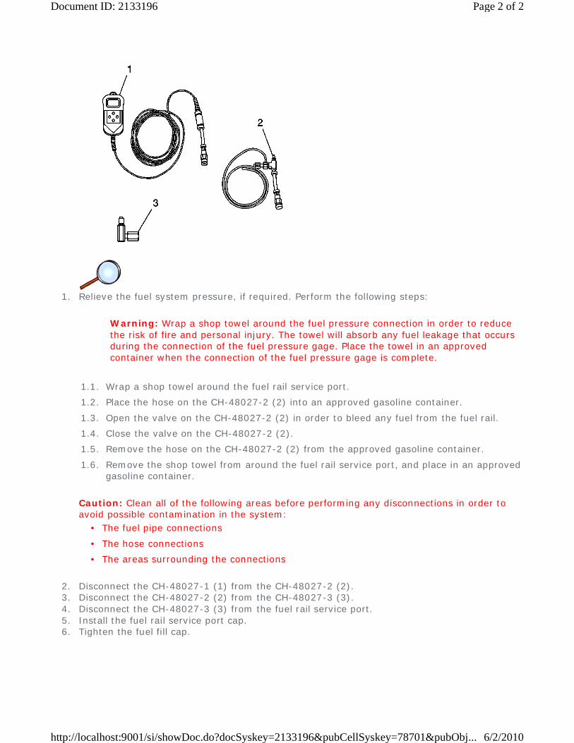
1. Relieve the fuel system pressure, if required. Perform the following steps:
Caution: Clean all of the following areas before performing any disconnections in order to avoid possible contamination in the system:
2. Disconnect the CH-48027-1 (1) from the CH-48027-2 (2). 3. Disconnect the CH-48027-2 (2) from the CH-48027-3 (3). 4. Disconnect the CH-48027-3 (3) from the fuel rail service port. 5. Install the fuel rail service port cap. 6. Tighten the fuel fill cap.
Warning: Wrap a shop towel around the fuel pressure connection in order to reduce the risk of fire and personal injury. The towel will absorb any fuel leakage that occurs during the connection of the fuel pressure gage. Place the towel in an approved container when the connection of the fuel pressure gage is complete.
1.1. Wrap a shop towel around the fuel rail service port.
1.2. Place the hose on the CH-48027-2 (2) into an approved gasoline container.
1.3. Open the valve on the CH-48027-2 (2) in order to bleed any fuel from the fuel rail.
1.4. Close the valve on the CH-48027-2 (2).
1.5. Remove the hose on the CH-48027-2 (2) from the approved gasoline container.
1.6. Remove the shop towel from around the fuel rail service port, and place in an approved gasoline container.
• The fuel pipe connections
• The hose connections
• The areas surrounding the connections
Page 2 of 2Document ID: 2133196
6/2/2010http://localhost:9001/si/showDoc.do?docSyskey=2133196&pubCellSyskey=78701&pubObj...
2009 Chevrolet Malibu | Malibu (VIN Z) Service Manual | Engine | Engine Controls and Fuel - 2.8L, 3.0L, 3.2L, or 3.6L | Repair Instructions | Document ID: 2074137
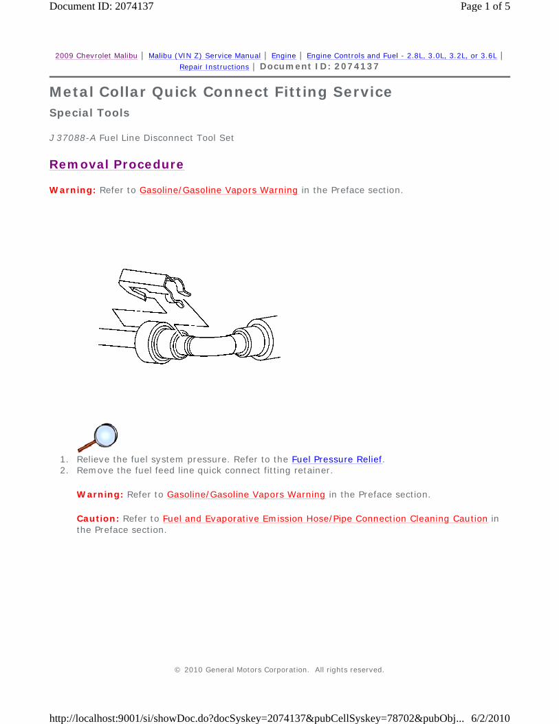
Metal Collar Quick Connect Fitting Service
Special Tools
J 37088-A Fuel Line Disconnect Tool Set
Removal Procedure
Warning: Refer to Gasoline/Gasoline Vapors Warning in the Preface section.
1. Relieve the fuel system pressure. Refer to the Fuel Pressure Relief. 2. Remove the fuel feed line quick connect fitting retainer.
Warning: Refer to Gasoline/Gasoline Vapors Warning in the Preface section.
Caution: Refer to Fuel and Evaporative Emission Hose/Pipe Connection Cleaning Caution in the Preface section.
© 2010 General Motors Corporation. All rights reserved.
Page 1 of 5Document ID: 2074137
6/2/2010http://localhost:9001/si/showDoc.do?docSyskey=2074137&pubCellSyskey=78702&pubObj...
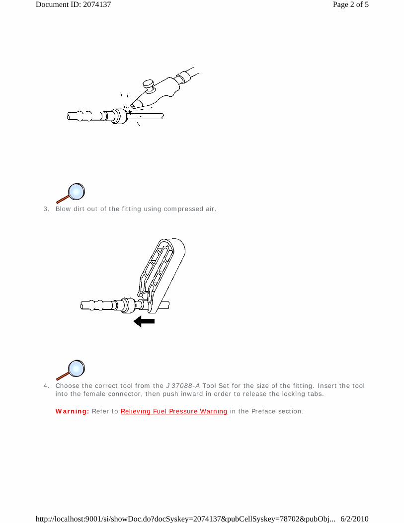
3. Blow dirt out of the fitting using compressed air.
4. Choose the correct tool from the J 37088-A Tool Set for the size of the fitting. Insert the tool
into the female connector, then push inward in order to release the locking tabs.
Warning: Refer to Relieving Fuel Pressure Warning in the Preface section.
Page 2 of 5Document ID: 2074137
6/2/2010http://localhost:9001/si/showDoc.do?docSyskey=2074137&pubCellSyskey=78702&pubObj...
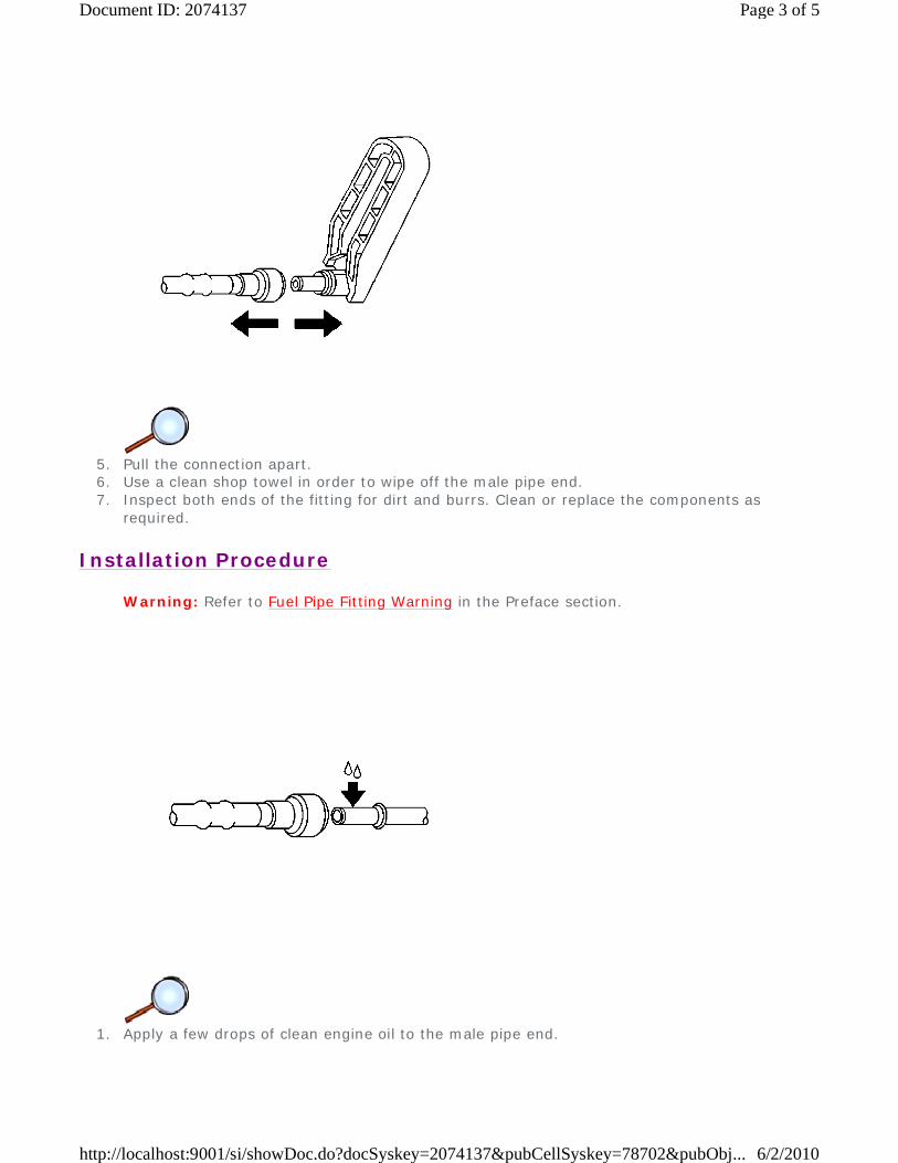
5. Pull the connection apart. 6. Use a clean shop towel in order to wipe off the male pipe end. 7. Inspect both ends of the fitting for dirt and burrs. Clean or replace the components as
required.
Installation Procedure
Warning: Refer to Fuel Pipe Fitting Warning in the Preface section.
1. Apply a few drops of clean engine oil to the male pipe end.
Page 3 of 5Document ID: 2074137
6/2/2010http://localhost:9001/si/showDoc.do?docSyskey=2074137&pubCellSyskey=78702&pubObj...

2. Push both sides of the fitting together in order to snap the retaining tabs into place.
3. Once installed, pull on both sides of the fitting in order to make sure the connection is
secure.
Page 4 of 5Document ID: 2074137
6/2/2010http://localhost:9001/si/showDoc.do?docSyskey=2074137&pubCellSyskey=78702&pubObj...
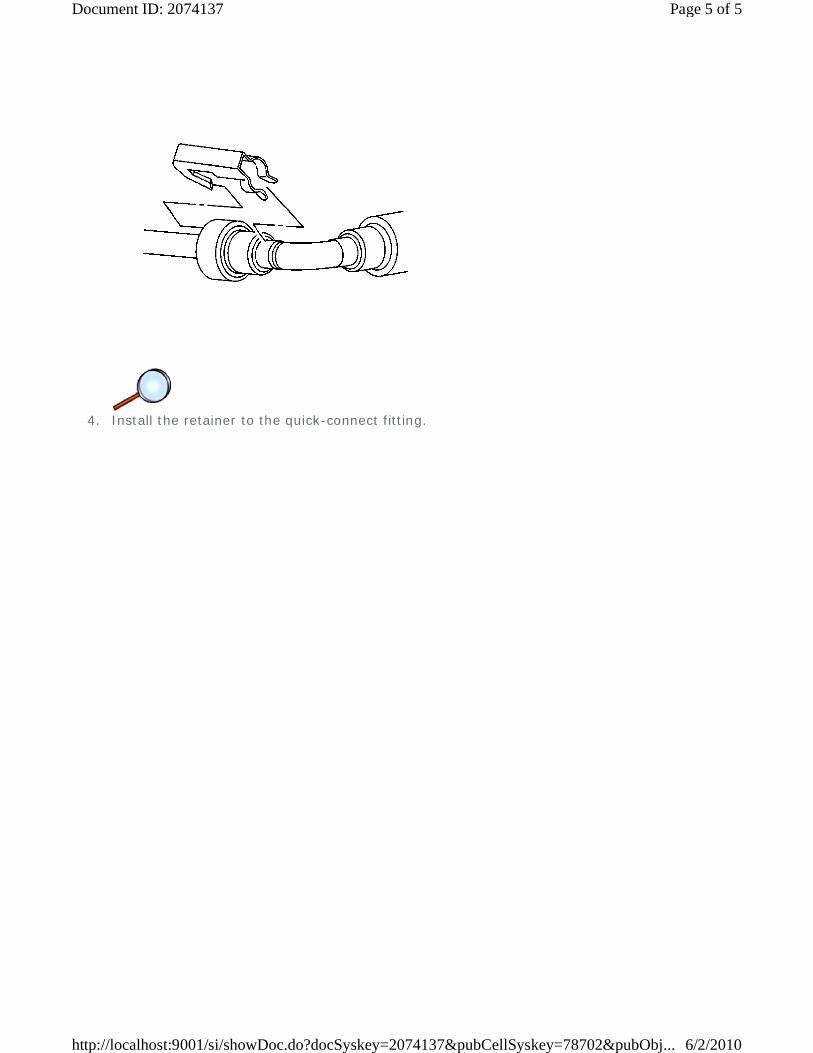
4. Install the retainer to the quick-connect fitting.
Page 5 of 5Document ID: 2074137
6/2/2010http://localhost:9001/si/showDoc.do?docSyskey=2074137&pubCellSyskey=78702&pubObj...
2009 Chevrolet Malibu | Malibu (VIN Z) Service Manual | Engine | Engine Controls and Fuel - 2.8L, 3.0L, 3.2L, or 3.6L | Repair Instructions | Document ID: 2074148
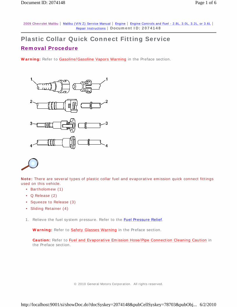
Plastic Collar Quick Connect Fitting Service
Removal Procedure
Warning: Refer to Gasoline/Gasoline Vapors Warning in the Preface section.
Note: There are several types of plastic collar fuel and evaporative emission quick connect fittings used on this vehicle.
1. Relieve the fuel system pressure. Refer to the Fuel Pressure Relief.
Warning: Refer to Safety Glasses Warning in the Preface section.
Caution: Refer to Fuel and Evaporative Emission Hose/Pipe Connection Cleaning Caution in the Preface section.
• Bartholomew (1)
• Q Release (2)
• Squeeze to Release (3)
• Sliding Retainer (4)
© 2010 General Motors Corporation. All rights reserved.
Page 1 of 6Document ID: 2074148
6/2/2010http://localhost:9001/si/showDoc.do?docSyskey=2074148&pubCellSyskey=78703&pubObj...
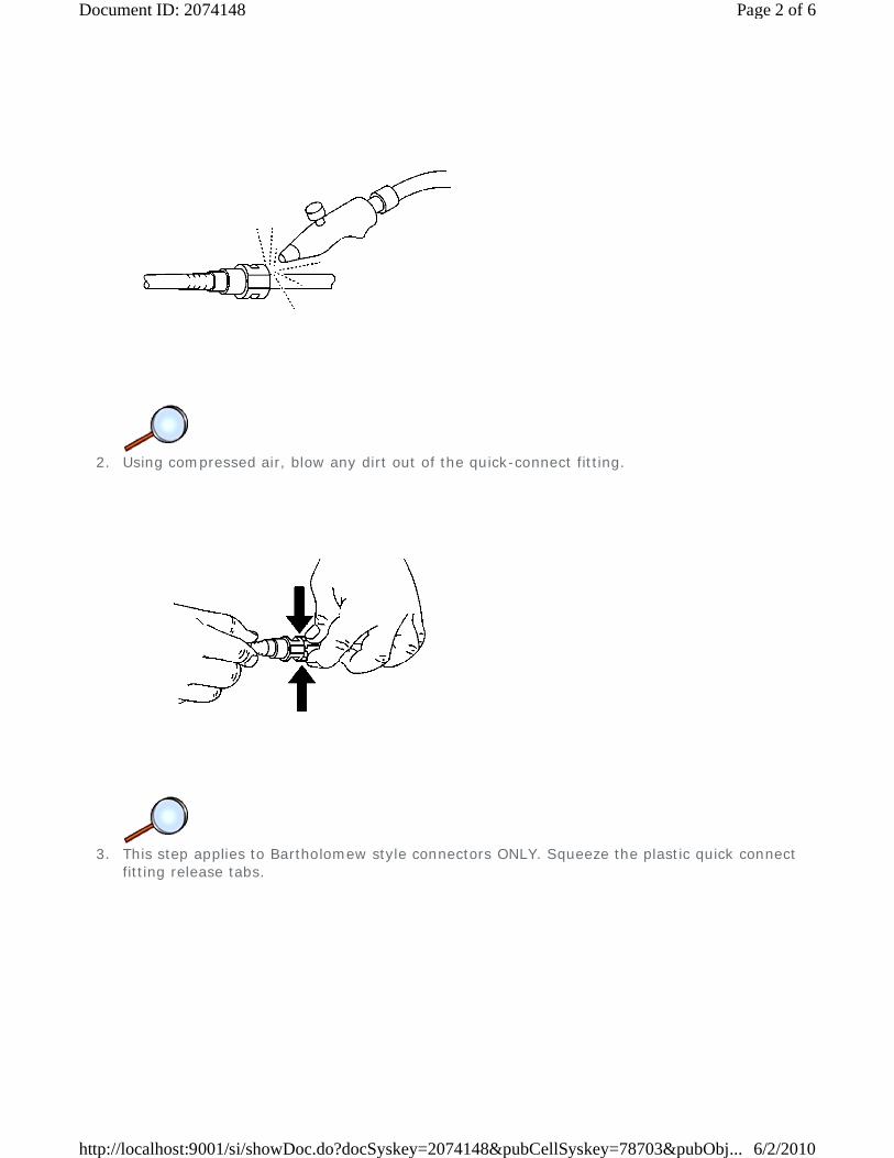
2. Using compressed air, blow any dirt out of the quick-connect fitting.
3. This step applies to Bartholomew style connectors ONLY. Squeeze the plastic quick connect
fitting release tabs.
Page 2 of 6Document ID: 2074148
6/2/2010http://localhost:9001/si/showDoc.do?docSyskey=2074148&pubCellSyskey=78703&pubObj...
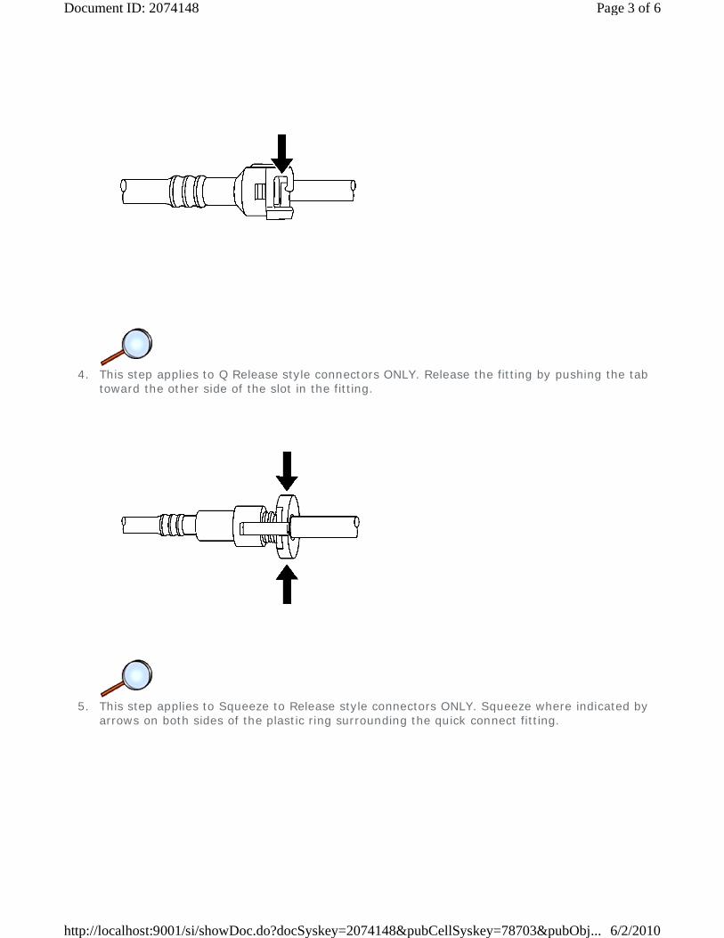
4. This step applies to Q Release style connectors ONLY. Release the fitting by pushing the tab
toward the other side of the slot in the fitting.
5. This step applies to Squeeze to Release style connectors ONLY. Squeeze where indicated by
arrows on both sides of the plastic ring surrounding the quick connect fitting.
Page 3 of 6Document ID: 2074148
6/2/2010http://localhost:9001/si/showDoc.do?docSyskey=2074148&pubCellSyskey=78703&pubObj...
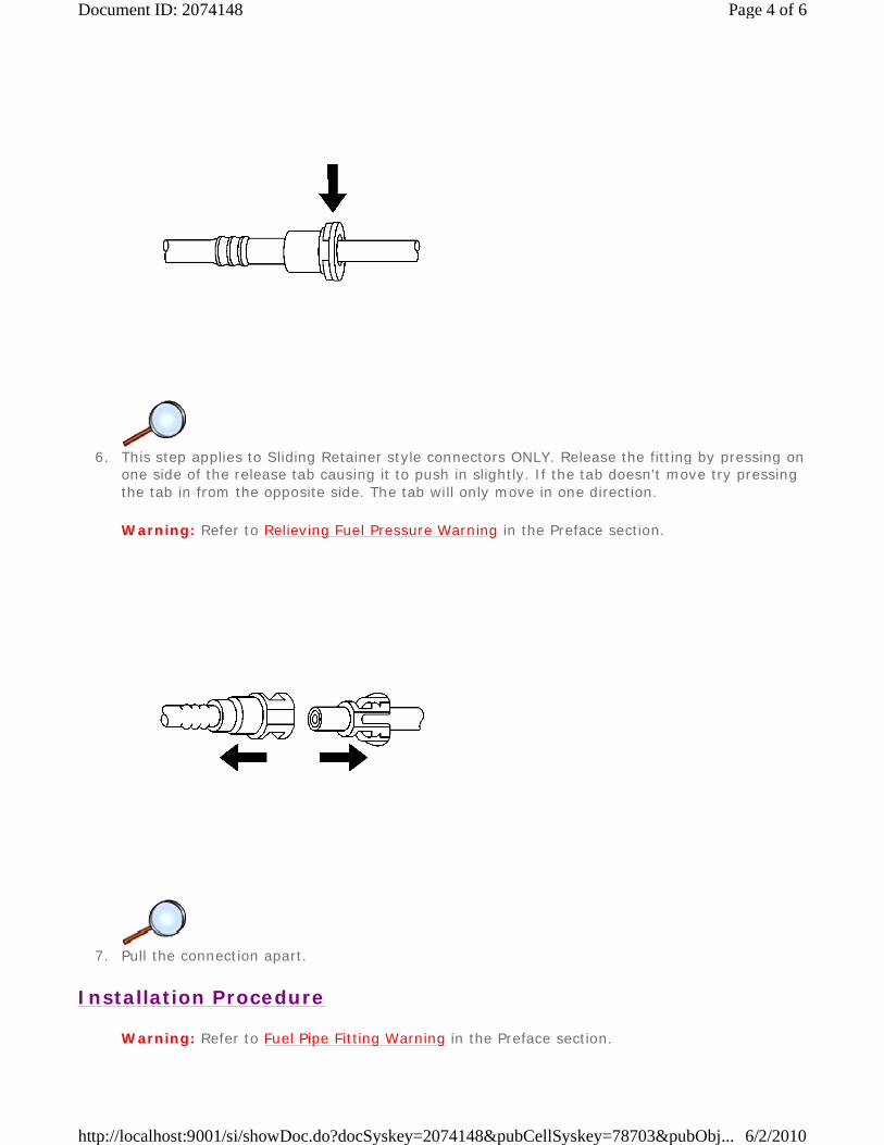
6. This step applies to Sliding Retainer style connectors ONLY. Release the fitting by pressing on
one side of the release tab causing it to push in slightly. If the tab doesn't move try pressing the tab in from the opposite side. The tab will only move in one direction.
Warning: Refer to Relieving Fuel Pressure Warning in the Preface section.
7. Pull the connection apart.
Installation Procedure
Warning: Refer to Fuel Pipe Fitting Warning in the Preface section.
Page 4 of 6Document ID: 2074148
6/2/2010http://localhost:9001/si/showDoc.do?docSyskey=2074148&pubCellSyskey=78703&pubObj...

1. Apply a few drops of clean engine oil to the male connection end.
2. Push both sides of the quick-connect fitting together in order to cause the retaining feature to
snap into place.
Page 5 of 6Document ID: 2074148
6/2/2010http://localhost:9001/si/showDoc.do?docSyskey=2074148&pubCellSyskey=78703&pubObj...
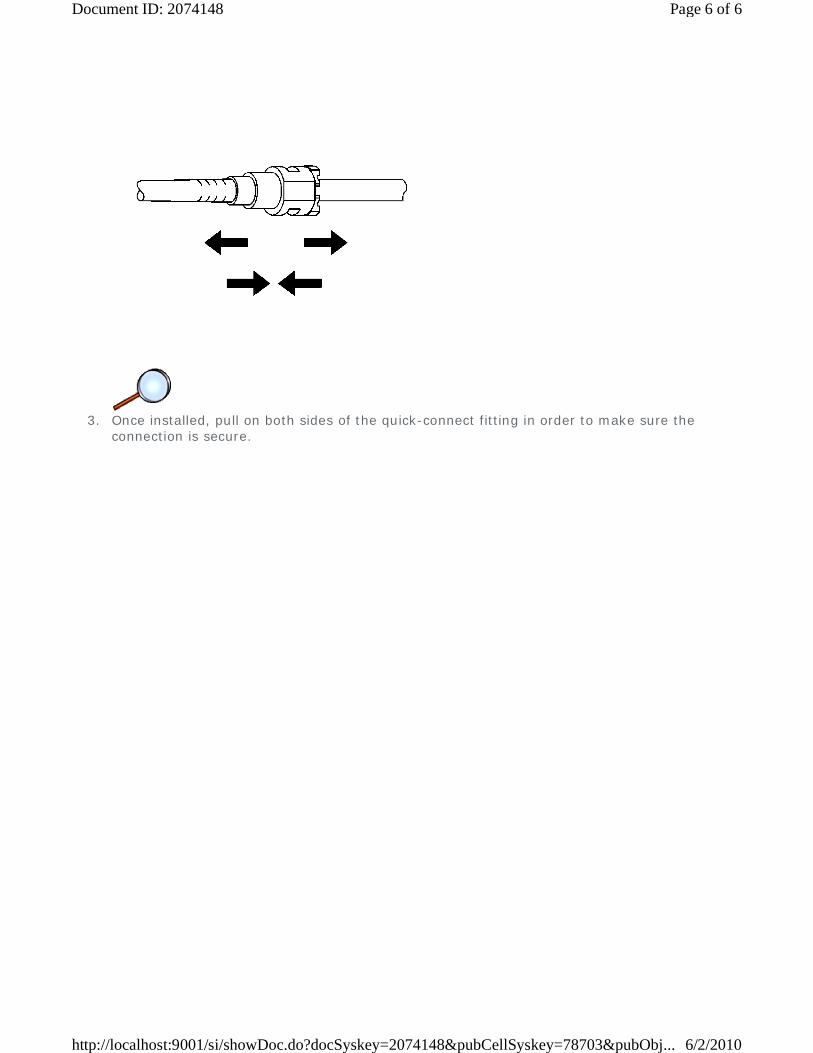
3. Once installed, pull on both sides of the quick-connect fitting in order to make sure the
connection is secure.
Page 6 of 6Document ID: 2074148
6/2/2010http://localhost:9001/si/showDoc.do?docSyskey=2074148&pubCellSyskey=78703&pubObj...
2009 Chevrolet Malibu | Malibu (VIN Z) Service Manual | Engine | Engine Controls and Fuel - 2.8L, 3.0L, 3.2L, or 3.6L | Repair Instructions | Document ID: 1838944
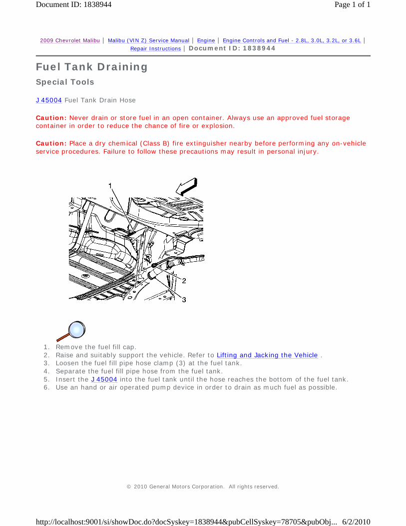
Fuel Tank Draining
Special Tools
J 45004 Fuel Tank Drain Hose
Caution: Never drain or store fuel in an open container. Always use an approved fuel storage container in order to reduce the chance of fire or explosion.
Caution: Place a dry chemical (Class B) fire extinguisher nearby before performing any on-vehicle service procedures. Failure to follow these precautions may result in personal injury.
1. Remove the fuel fill cap. 2. Raise and suitably support the vehicle. Refer to Lifting and Jacking the Vehicle . 3. Loosen the fuel fill pipe hose clamp (3) at the fuel tank. 4. Separate the fuel fill pipe hose from the fuel tank. 5. Insert the J 45004 into the fuel tank until the hose reaches the bottom of the fuel tank. 6. Use an hand or air operated pump device in order to drain as much fuel as possible.
© 2010 General Motors Corporation. All rights reserved.
Page 1 of 1Document ID: 1838944
6/2/2010http://localhost:9001/si/showDoc.do?docSyskey=1838944&pubCellSyskey=78705&pubObj...
2009 Chevrolet Malibu | Malibu (VIN Z) Service Manual | Engine | Engine Controls and Fuel - 2.8L, 3.0L, 3.2L, or 3.6L | Repair Instructions | Document ID: 2155173
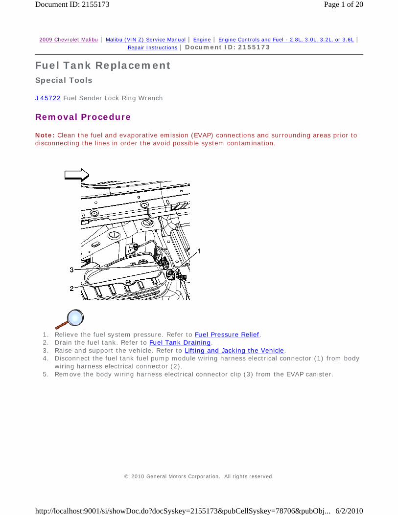
Fuel Tank Replacement
Special Tools
J 45722 Fuel Sender Lock Ring Wrench
Removal Procedure
Note: Clean the fuel and evaporative emission (EVAP) connections and surrounding areas prior to disconnecting the lines in order the avoid possible system contamination.
1. Relieve the fuel system pressure. Refer to Fuel Pressure Relief. 2. Drain the fuel tank. Refer to Fuel Tank Draining. 3. Raise and support the vehicle. Refer to Lifting and Jacking the Vehicle. 4. Disconnect the fuel tank fuel pump module wiring harness electrical connector (1) from body
wiring harness electrical connector (2). 5. Remove the body wiring harness electrical connector clip (3) from the EVAP canister.
© 2010 General Motors Corporation. All rights reserved.
Page 1 of 20Document ID: 2155173
6/2/2010http://localhost:9001/si/showDoc.do?docSyskey=2155173&pubCellSyskey=78706&pubObj...
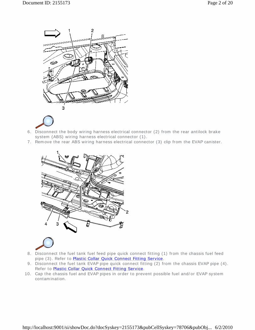
6. Disconnect the body wiring harness electrical connector (2) from the rear antilock brake
system (ABS) wiring harness electrical connector (1). 7. Remove the rear ABS wiring harness electrical connector (3) clip from the EVAP canister.
8. Disconnect the fuel tank fuel feed pipe quick connect fitting (1) from the chassis fuel feed
pipe (3). Refer to Plastic Collar Quick Connect Fitting Service. 9. Disconnect the fuel tank EVAP pipe quick connect fitting (2) from the chassis EVAP pipe (4).
Refer to Plastic Collar Quick Connect Fitting Service. 10. Cap the chassis fuel and EVAP pipes in order to prevent possible fuel and/or EVAP system
contamination.
Page 2 of 20Document ID: 2155173
6/2/2010http://localhost:9001/si/showDoc.do?docSyskey=2155173&pubCellSyskey=78706&pubObj...

11. Disconnect the fuel tank fill EVAP emission pipe quick connect fitting (2) from the fuel tank
vent pipe (1). Refer to Plastic Collar Quick Connect Fitting Service.
12. Place a jackstand under the muffler assembly. 13. With the aid of an assistant, separate the muffler insulators (1) from the underbody hangers. 14. Slowly lower the muffler assembly allowing it to rest on the jackstand. If this is not possible,
remove the muffler assembly. Refer to Exhaust Muffler Replacement.
Page 3 of 20Document ID: 2155173
6/2/2010http://localhost:9001/si/showDoc.do?docSyskey=2155173&pubCellSyskey=78706&pubObj...
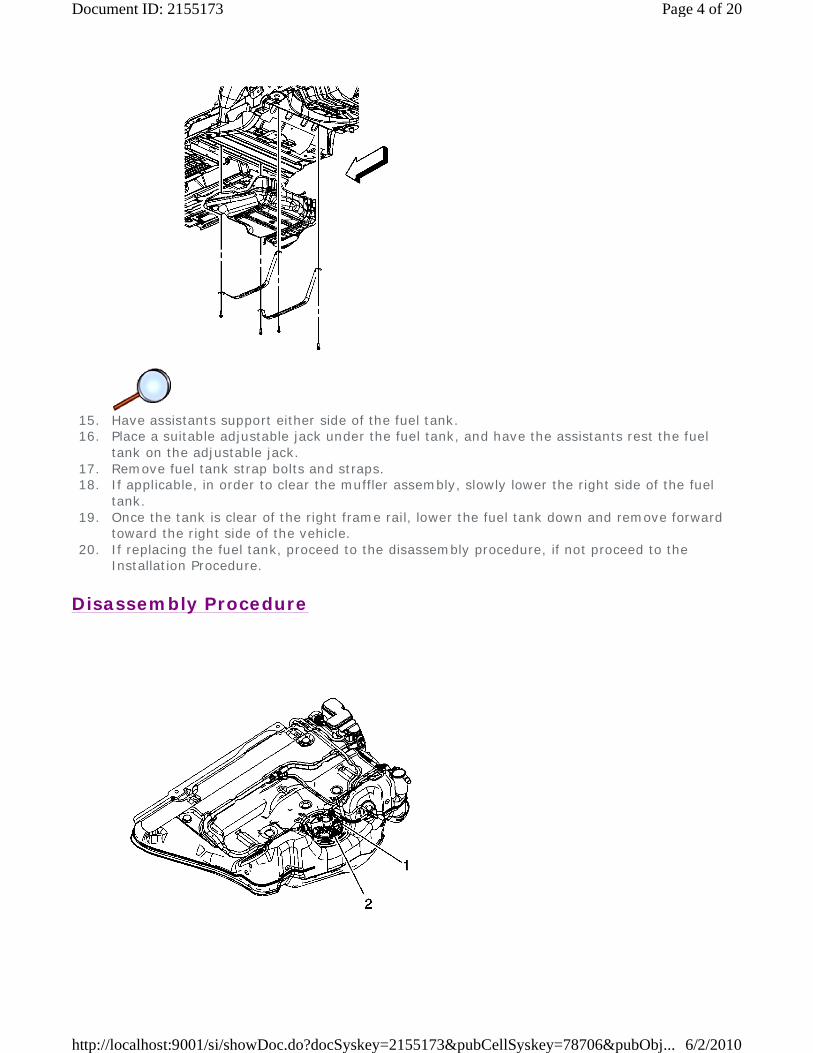
15. Have assistants support either side of the fuel tank. 16. Place a suitable adjustable jack under the fuel tank, and have the assistants rest the fuel
tank on the adjustable jack. 17. Remove fuel tank strap bolts and straps. 18. If applicable, in order to clear the muffler assembly, slowly lower the right side of the fuel
tank. 19. Once the tank is clear of the right frame rail, lower the fuel tank down and remove forward
toward the right side of the vehicle. 20. If replacing the fuel tank, proceed to the disassembly procedure, if not proceed to the
Installation Procedure.
Disassembly Procedure
Page 4 of 20Document ID: 2155173
6/2/2010http://localhost:9001/si/showDoc.do?docSyskey=2155173&pubCellSyskey=78706&pubObj...
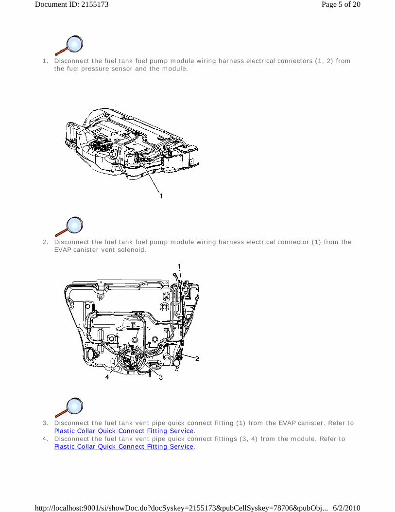
1. Disconnect the fuel tank fuel pump module wiring harness electrical connectors (1, 2) from
the fuel pressure sensor and the module.
2. Disconnect the fuel tank fuel pump module wiring harness electrical connector (1) from the
EVAP canister vent solenoid.
3. Disconnect the fuel tank vent pipe quick connect fitting (1) from the EVAP canister. Refer to
Plastic Collar Quick Connect Fitting Service. 4. Disconnect the fuel tank vent pipe quick connect fittings (3, 4) from the module. Refer to
Plastic Collar Quick Connect Fitting Service.
Page 5 of 20Document ID: 2155173
6/2/2010http://localhost:9001/si/showDoc.do?docSyskey=2155173&pubCellSyskey=78706&pubObj...
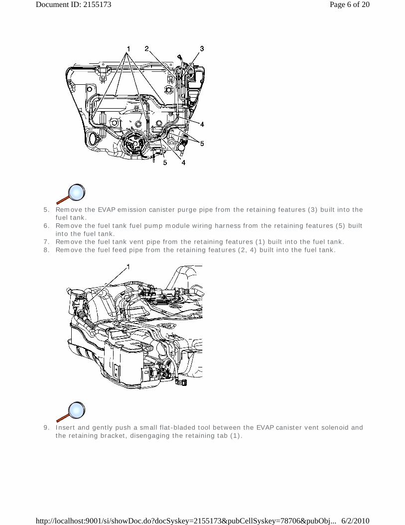
5. Remove the EVAP emission canister purge pipe from the retaining features (3) built into the
fuel tank. 6. Remove the fuel tank fuel pump module wiring harness from the retaining features (5) built
into the fuel tank. 7. Remove the fuel tank vent pipe from the retaining features (1) built into the fuel tank. 8. Remove the fuel feed pipe from the retaining features (2, 4) built into the fuel tank.
9. Insert and gently push a small flat-bladed tool between the EVAP canister vent solenoid and
the retaining bracket, disengaging the retaining tab (1).
Page 6 of 20Document ID: 2155173
6/2/2010http://localhost:9001/si/showDoc.do?docSyskey=2155173&pubCellSyskey=78706&pubObj...
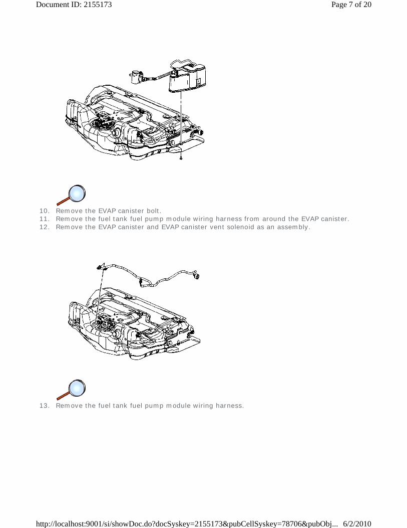
10. Remove the EVAP canister bolt. 11. Remove the fuel tank fuel pump module wiring harness from around the EVAP canister. 12. Remove the EVAP canister and EVAP canister vent solenoid as an assembly.
13. Remove the fuel tank fuel pump module wiring harness.
Page 7 of 20Document ID: 2155173
6/2/2010http://localhost:9001/si/showDoc.do?docSyskey=2155173&pubCellSyskey=78706&pubObj...

14. Remove the fuel tank vent pipe from the fuel tank.
15. Install the J 45722 to the fuel pump module lock ring.
Page 8 of 20Document ID: 2155173
6/2/2010http://localhost:9001/si/showDoc.do?docSyskey=2155173&pubCellSyskey=78706&pubObj...
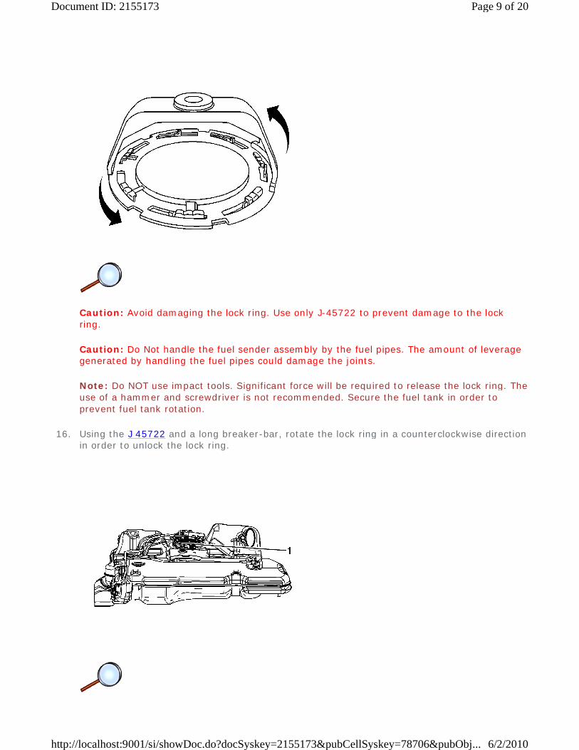
Caution: Avoid damaging the lock ring. Use only J-45722 to prevent damage to the lock ring.
Caution: Do Not handle the fuel sender assembly by the fuel pipes. The amount of leverage generated by handling the fuel pipes could damage the joints.
Note: Do NOT use impact tools. Significant force will be required to release the lock ring. The use of a hammer and screwdriver is not recommended. Secure the fuel tank in order to prevent fuel tank rotation.
16. Using the J 45722 and a long breaker-bar, rotate the lock ring in a counterclockwise direction in order to unlock the lock ring.
Page 9 of 20Document ID: 2155173
6/2/2010http://localhost:9001/si/showDoc.do?docSyskey=2155173&pubCellSyskey=78706&pubObj...
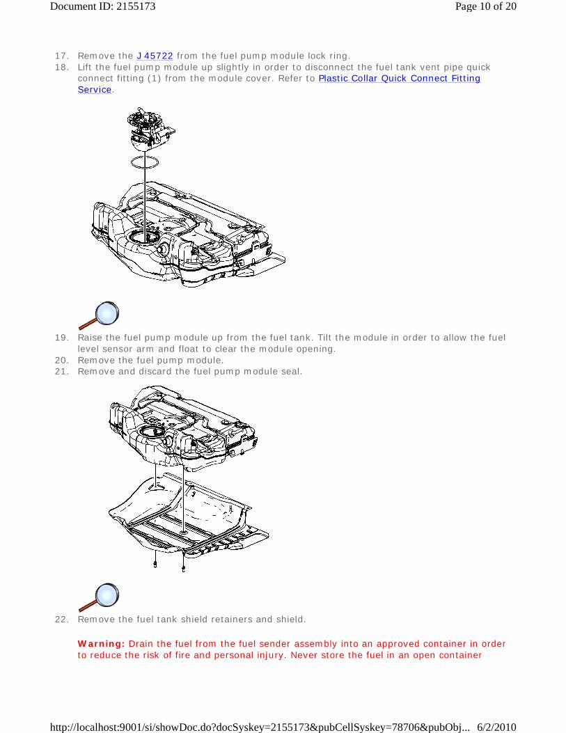
17. Remove the J 45722 from the fuel pump module lock ring. 18. Lift the fuel pump module up slightly in order to disconnect the fuel tank vent pipe quick
connect fitting (1) from the module cover. Refer to Plastic Collar Quick Connect Fitting Service.
19. Raise the fuel pump module up from the fuel tank. Tilt the module in order to allow the fuel
level sensor arm and float to clear the module opening. 20. Remove the fuel pump module. 21. Remove and discard the fuel pump module seal.
22. Remove the fuel tank shield retainers and shield.
Warning: Drain the fuel from the fuel sender assembly into an approved container in order to reduce the risk of fire and personal injury. Never store the fuel in an open container
Page 10 of 20Document ID: 2155173
6/2/2010http://localhost:9001/si/showDoc.do?docSyskey=2155173&pubCellSyskey=78706&pubObj...
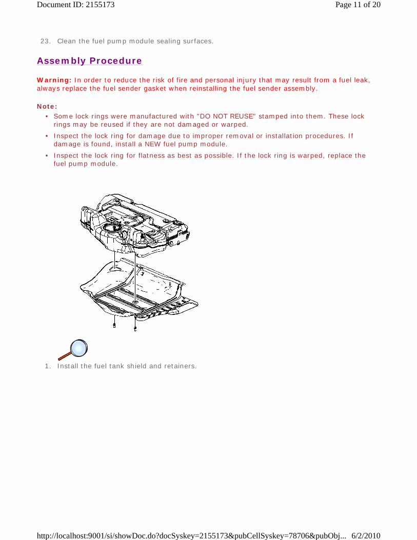
23. Clean the fuel pump module sealing surfaces.
Assembly Procedure
Warning: In order to reduce the risk of fire and personal injury that may result from a fuel leak, always replace the fuel sender gasket when reinstalling the fuel sender assembly.
Note:
1. Install the fuel tank shield and retainers.
• Some lock rings were manufactured with "DO NOT REUSE" stamped into them. These lock rings may be reused if they are not damaged or warped.
• Inspect the lock ring for damage due to improper removal or installation procedures. If damage is found, install a NEW fuel pump module.
• Inspect the lock ring for flatness as best as possible. If the lock ring is warped, replace the fuel pump module.
Page 11 of 20Document ID: 2155173
6/2/2010http://localhost:9001/si/showDoc.do?docSyskey=2155173&pubCellSyskey=78706&pubObj...
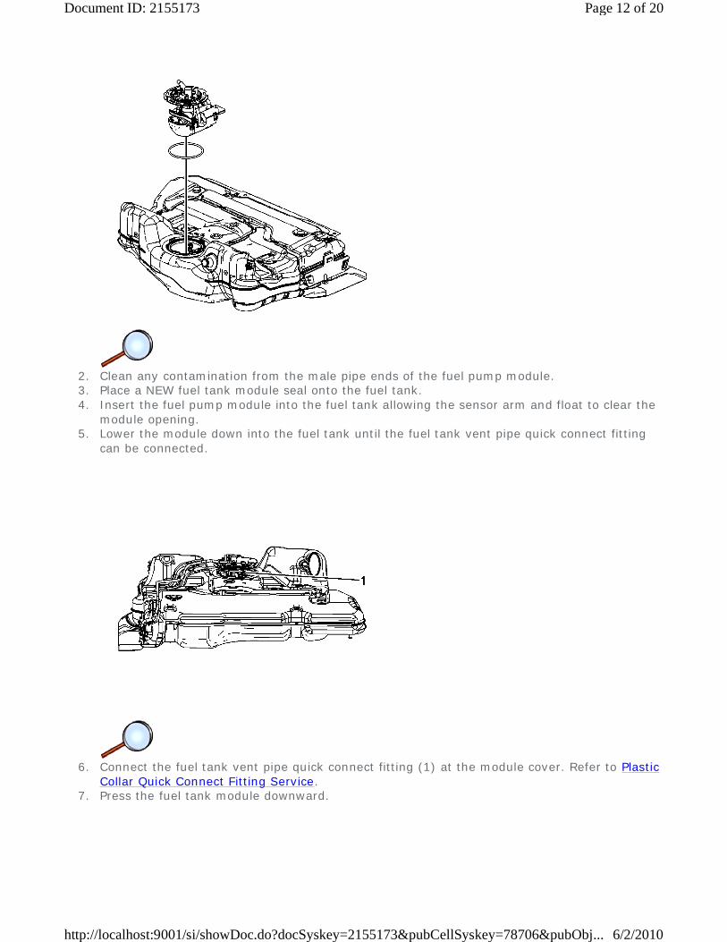
2. Clean any contamination from the male pipe ends of the fuel pump module. 3. Place a NEW fuel tank module seal onto the fuel tank. 4. Insert the fuel pump module into the fuel tank allowing the sensor arm and float to clear the
module opening. 5. Lower the module down into the fuel tank until the fuel tank vent pipe quick connect fitting
can be connected.
6. Connect the fuel tank vent pipe quick connect fitting (1) at the module cover. Refer to Plastic
Collar Quick Connect Fitting Service. 7. Press the fuel tank module downward.
Page 12 of 20Document ID: 2155173
6/2/2010http://localhost:9001/si/showDoc.do?docSyskey=2155173&pubCellSyskey=78706&pubObj...
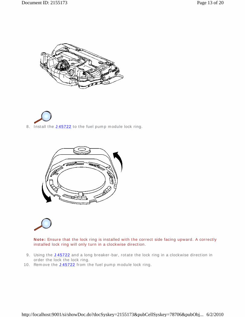
8. Install the J 45722 to the fuel pump module lock ring.
Note: Ensure that the lock ring is installed with the correct side facing upward. A correctly installed lock ring will only turn in a clockwise direction.
9. Using the J 45722 and a long breaker-bar, rotate the lock ring in a clockwise direction in order the lock the lock ring.
10. Remove the J 45722 from the fuel pump module lock ring.
Page 13 of 20Document ID: 2155173
6/2/2010http://localhost:9001/si/showDoc.do?docSyskey=2155173&pubCellSyskey=78706&pubObj...
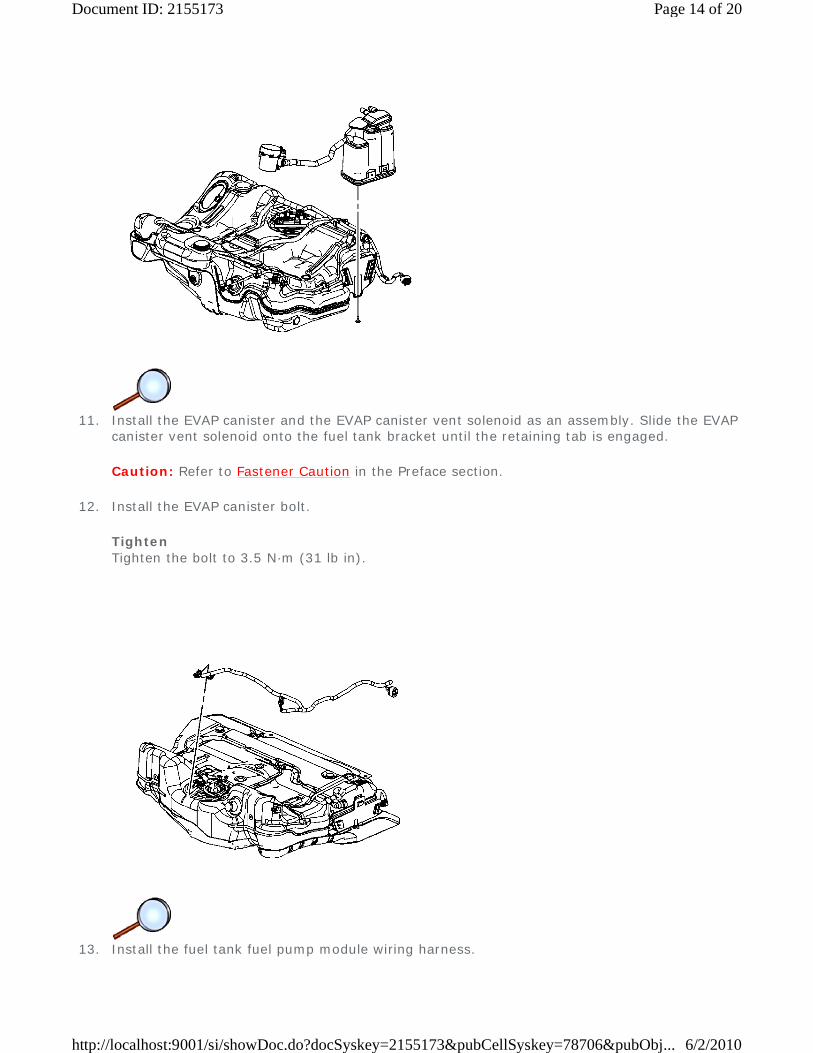
11. Install the EVAP canister and the EVAP canister vent solenoid as an assembly. Slide the EVAP
canister vent solenoid onto the fuel tank bracket until the retaining tab is engaged.
Caution: Refer to Fastener Caution in the Preface section.
12. Install the EVAP canister bolt.
Tighten Tighten the bolt to 3.5 N·m (31 lb in).
13. Install the fuel tank fuel pump module wiring harness.
Page 14 of 20Document ID: 2155173
6/2/2010http://localhost:9001/si/showDoc.do?docSyskey=2155173&pubCellSyskey=78706&pubObj...
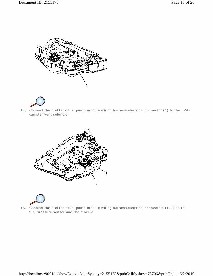
14. Connect the fuel tank fuel pump module wiring harness electrical connector (1) to the EVAP
canister vent solenoid.
15. Connect the fuel tank fuel pump module wiring harness electrical connectors (1, 2) to the
fuel pressure sensor and the module.
Page 15 of 20Document ID: 2155173
6/2/2010http://localhost:9001/si/showDoc.do?docSyskey=2155173&pubCellSyskey=78706&pubObj...

16. Install the fuel tank vent pipe to the fuel tank.
17. Connect the fuel tank vent pipe quick connect fitting (1) to the EVAP canister. Refer to Plastic
Collar Quick Connect Fitting Service. 18. Connect the fuel tank vent pipe quick connect fittings (3, 4) to the module. Refer to Plastic
Collar Quick Connect Fitting Service.
Page 16 of 20Document ID: 2155173
6/2/2010http://localhost:9001/si/showDoc.do?docSyskey=2155173&pubCellSyskey=78706&pubObj...
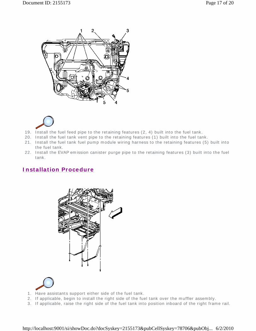
19. Install the fuel feed pipe to the retaining features (2, 4) built into the fuel tank. 20. Install the fuel tank vent pipe to the retaining features (1) built into the fuel tank. 21. Install the fuel tank fuel pump module wiring harness to the retaining features (5) built into
the fuel tank. 22. Install the EVAP emission canister purge pipe to the retaining features (3) built into the fuel
tank.
Installation Procedure
1. Have assistants support either side of the fuel tank. 2. If applicable, begin to install the right side of the fuel tank over the muffler assembly. 3. If applicable, raise the right side of the fuel tank into position inboard of the right frame rail.
Page 17 of 20Document ID: 2155173
6/2/2010http://localhost:9001/si/showDoc.do?docSyskey=2155173&pubCellSyskey=78706&pubObj...
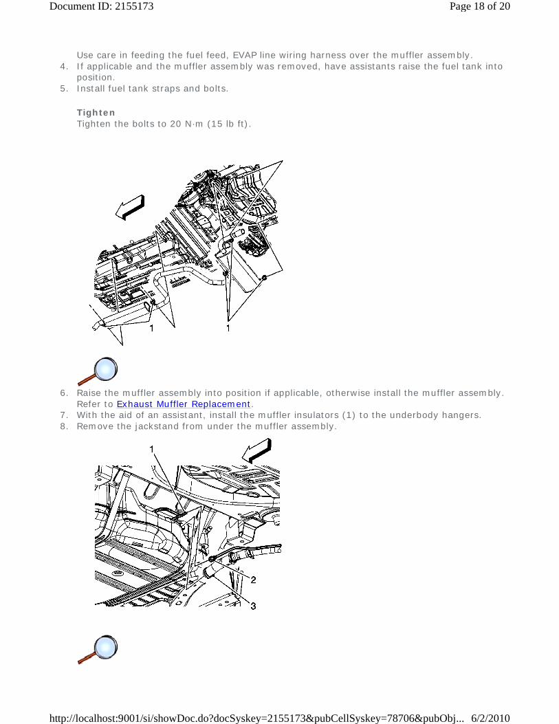
Use care in feeding the fuel feed, EVAP line wiring harness over the muffler assembly. 4. If applicable and the muffler assembly was removed, have assistants raise the fuel tank into
position. 5. Install fuel tank straps and bolts.
Tighten Tighten the bolts to 20 N·m (15 lb ft).
6. Raise the muffler assembly into position if applicable, otherwise install the muffler assembly.
Refer to Exhaust Muffler Replacement. 7. With the aid of an assistant, install the muffler insulators (1) to the underbody hangers. 8. Remove the jackstand from under the muffler assembly.
Page 18 of 20Document ID: 2155173
6/2/2010http://localhost:9001/si/showDoc.do?docSyskey=2155173&pubCellSyskey=78706&pubObj...

9. Install the fuel fill pipe hose to the fuel tank. 10. Connect the fuel tank fill EVAP emission pipe quick connect fitting (2) to the fuel tank vent
pipe (1). Refer to Plastic Collar Quick Connect Fitting Service. 11. Tighten the fuel fill pipe hose clamp (3) at the fuel tank.
Tighten Tighten the clamp to 4 N·m (35 lb in).
12. Remove the caps from the fuel and EVAP pipes. 13. Connect the fuel tank EVAP pipe quick connect fitting (2) to the chassis EVAP pipe (4). Refer
to Plastic Collar Quick Connect Fitting Service. 14. Connect the fuel tank fuel feed pipe quick connect fitting (1) to the chassis fuel feed pipe (3).
Refer to Plastic Collar Quick Connect Fitting Service.
Page 19 of 20Document ID: 2155173
6/2/2010http://localhost:9001/si/showDoc.do?docSyskey=2155173&pubCellSyskey=78706&pubObj...
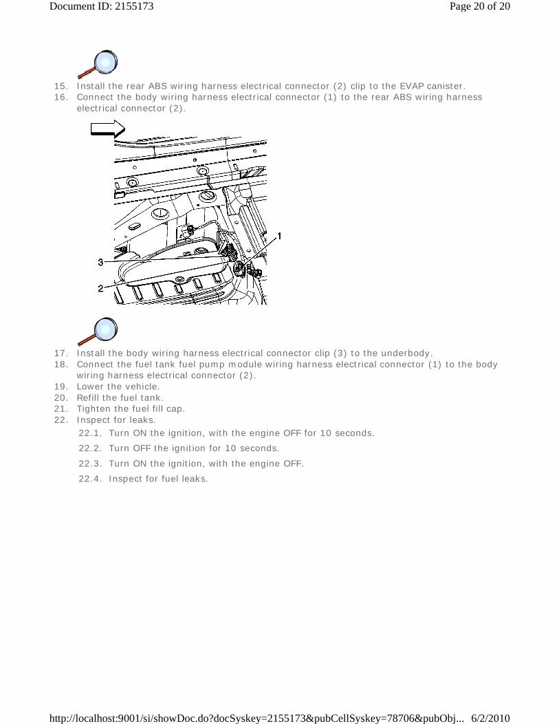
15. Install the rear ABS wiring harness electrical connector (2) clip to the EVAP canister. 16. Connect the body wiring harness electrical connector (1) to the rear ABS wiring harness
electrical connector (2).
17. Install the body wiring harness electrical connector clip (3) to the underbody. 18. Connect the fuel tank fuel pump module wiring harness electrical connector (1) to the body
wiring harness electrical connector (2). 19. Lower the vehicle. 20. Refill the fuel tank. 21. Tighten the fuel fill cap. 22. Inspect for leaks.
22.1. Turn ON the ignition, with the engine OFF for 10 seconds.
22.2. Turn OFF the ignition for 10 seconds.
22.3. Turn ON the ignition, with the engine OFF.
22.4. Inspect for fuel leaks.
Page 20 of 20Document ID: 2155173
6/2/2010http://localhost:9001/si/showDoc.do?docSyskey=2155173&pubCellSyskey=78706&pubObj...
2009 Chevrolet Malibu | Malibu (VIN Z) Service Manual | Engine | Engine Controls and Fuel - 2.8L, 3.0L, 3.2L, or 3.6L | Repair Instructions | Document ID: 2089245
Fuel Tank Fuel Pump Module Replacement
Special Tools
J 45722 Fuel Sender Lock Ring Wrench
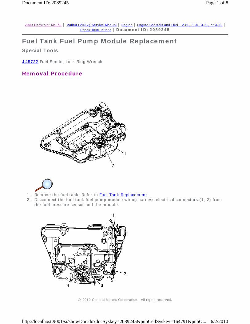
Removal Procedure
1. Remove the fuel tank. Refer to Fuel Tank Replacement. 2. Disconnect the fuel tank fuel pump module wiring harness electrical connectors (1, 2) from
the fuel pressure sensor and the module.
© 2010 General Motors Corporation. All rights reserved.
Page 1 of 8Document ID: 2089245
6/2/2010http://localhost:9001/si/showDoc.do?docSyskey=2089245&pubCellSyskey=164791&pubO...

3. Disconnect the fuel tank vent pipe quick connect fittings (3, 4) from the module. Refer to
Plastic Collar Quick Connect Fitting Service.
4. Remove the fuel feed pipe from the retaining features (1) built into the fuel tank.
5. Install the J 45722 to the fuel pump module lock ring.
Page 2 of 8Document ID: 2089245
6/2/2010http://localhost:9001/si/showDoc.do?docSyskey=2089245&pubCellSyskey=164791&pubO...

Notice: Avoid damaging the lock ring. Use only J-45722 to prevent damage to the lock ring.
Notice: Do Not handle the fuel sender assembly by the fuel pipes. The amount of leverage generated by handling the fuel pipes could damage the joints.
Important: Do NOT use impact tools. Significant force will be required to release the lock ring. The use of a hammer and screwdriver is not recommended. Secure the fuel tank in order to prevent fuel tank rotation.
6. Using the J 45722 and a long breaker-bar, rotate the lock ring in a counterclockwise direction in order to unlock the lock ring.
7. Remove the J 45722 from the fuel pump module lock ring.
Page 3 of 8Document ID: 2089245
6/2/2010http://localhost:9001/si/showDoc.do?docSyskey=2089245&pubCellSyskey=164791&pubO...
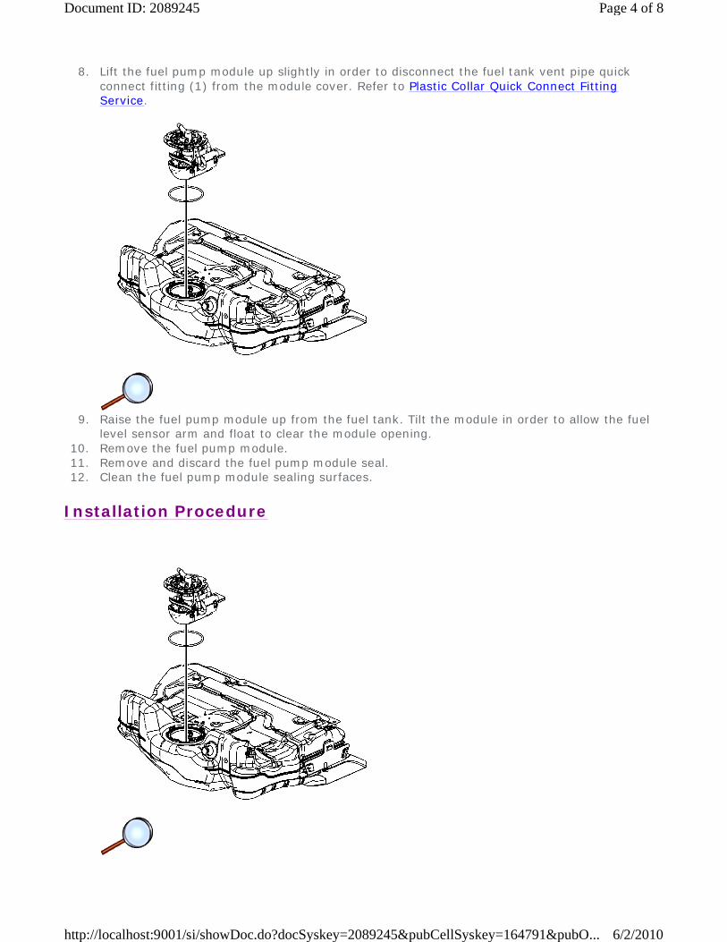
8. Lift the fuel pump module up slightly in order to disconnect the fuel tank vent pipe quick connect fitting (1) from the module cover. Refer to Plastic Collar Quick Connect Fitting Service.
9. Raise the fuel pump module up from the fuel tank. Tilt the module in order to allow the fuel
level sensor arm and float to clear the module opening. 10. Remove the fuel pump module. 11. Remove and discard the fuel pump module seal. 12. Clean the fuel pump module sealing surfaces.
Installation Procedure
Page 4 of 8Document ID: 2089245
6/2/2010http://localhost:9001/si/showDoc.do?docSyskey=2089245&pubCellSyskey=164791&pubO...
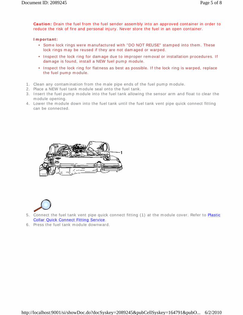
Caution: Drain the fuel from the fuel sender assembly into an approved container in order to reduce the risk of fire and personal injury. Never store the fuel in an open container.
Important:
1. Clean any contamination from the male pipe ends of the fuel pump module. 2. Place a NEW fuel tank module seal onto the fuel tank. 3. Insert the fuel pump module into the fuel tank allowing the sensor arm and float to clear the
module opening. 4. Lower the module down into the fuel tank until the fuel tank vent pipe quick connect fitting
can be connected.
5. Connect the fuel tank vent pipe quick connect fitting (1) at the module cover. Refer to Plastic
Collar Quick Connect Fitting Service. 6. Press the fuel tank module downward.
• Some lock rings were manufactured with "DO NOT REUSE" stamped into them. These lock rings may be reused if they are not damaged or warped.
• Inspect the lock ring for damage due to improper removal or installation procedures. If damage is found, install a NEW fuel pump module.
• Inspect the lock ring for flatness as best as possible. If the lock ring is warped, replace the fuel pump module.
Page 5 of 8Document ID: 2089245
6/2/2010http://localhost:9001/si/showDoc.do?docSyskey=2089245&pubCellSyskey=164791&pubO...

7. Install the J 45722 to the fuel pump module lock ring.
Important: Ensure that the lock ring is installed with the correct side facing upward. A correctly installed lock ring will only turn in a clockwise direction.
8. Using the J 45722 and a long breaker-bar, rotate the lock ring in a clockwise direction in order the lock the lock ring.
9. Remove the J 45722 from the fuel pump module lock ring.
Page 6 of 8Document ID: 2089245
6/2/2010http://localhost:9001/si/showDoc.do?docSyskey=2089245&pubCellSyskey=164791&pubO...
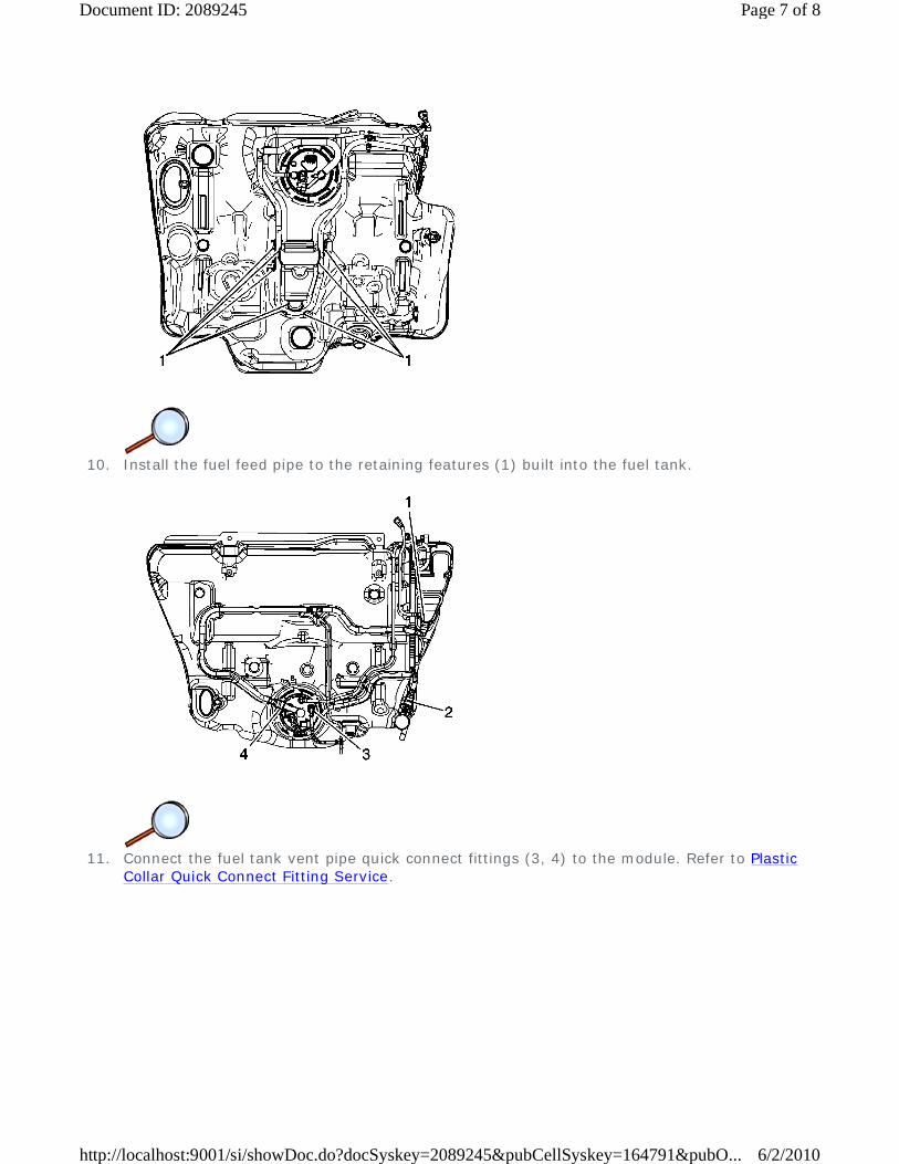
10. Install the fuel feed pipe to the retaining features (1) built into the fuel tank.
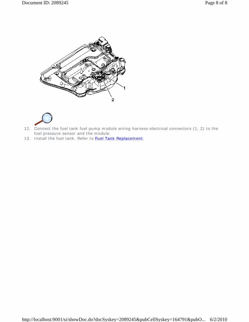
11. Connect the fuel tank vent pipe quick connect fittings (3, 4) to the module. Refer to Plastic
Collar Quick Connect Fitting Service.
Page 7 of 8Document ID: 2089245
6/2/2010http://localhost:9001/si/showDoc.do?docSyskey=2089245&pubCellSyskey=164791&pubO...
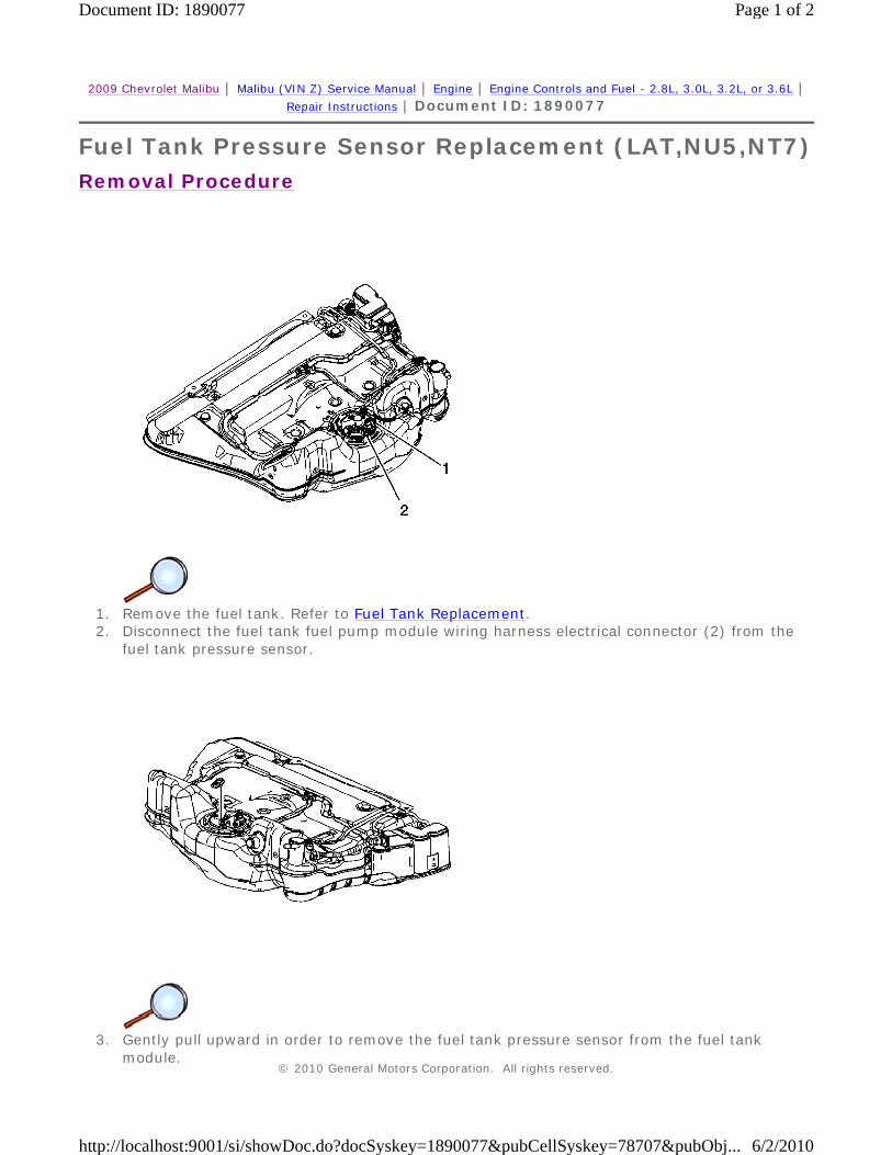
12. Connect the fuel tank fuel pump module wiring harness electrical connectors (1, 2) to the
fuel pressure sensor and the module. 13. Install the fuel tank. Refer to Fuel Tank Replacement.
Page 8 of 8Document ID: 2089245
6/2/2010http://localhost:9001/si/showDoc.do?docSyskey=2089245&pubCellSyskey=164791&pubO...
2009 Chevrolet Malibu | Malibu (VIN Z) Service Manual | Engine | Engine Controls and Fuel - 2.8L, 3.0L, 3.2L, or 3.6L | Repair Instructions | Document ID: 1890077
Fuel Tank Pressure Sensor Replacement (LAT,NU5,NT7)
Removal Procedure
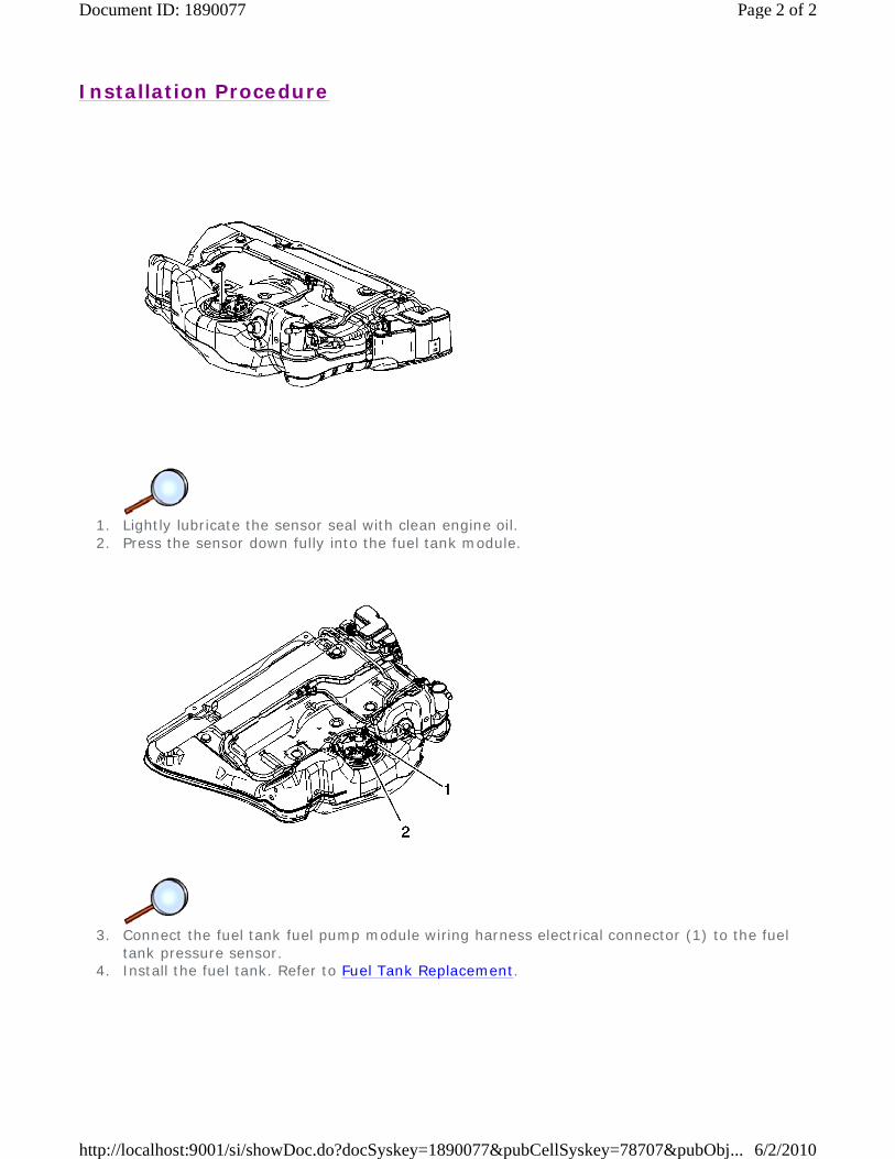
1. Remove the fuel tank. Refer to Fuel Tank Replacement. 2. Disconnect the fuel tank fuel pump module wiring harness electrical connector (2) from the
fuel tank pressure sensor.
3. Gently pull upward in order to remove the fuel tank pressure sensor from the fuel tank
module. © 2010 General Motors Corporation. All rights reserved.
Page 1 of 2Document ID: 1890077
6/2/2010http://localhost:9001/si/showDoc.do?docSyskey=1890077&pubCellSyskey=78707&pubObj...
Installation Procedure
1. Lightly lubricate the sensor seal with clean engine oil. 2. Press the sensor down fully into the fuel tank module.
3. Connect the fuel tank fuel pump module wiring harness electrical connector (1) to the fuel
tank pressure sensor. 4. Install the fuel tank. Refer to Fuel Tank Replacement.
Page 2 of 2Document ID: 1890077
6/2/2010http://localhost:9001/si/showDoc.do?docSyskey=1890077&pubCellSyskey=78707&pubObj...
2009 Chevrolet Malibu | Malibu (VIN Z) Service Manual | Engine | Engine Controls and Fuel - 2.8L, 3.0L, 3.2L, or 3.6L | Repair Instructions | Document ID: 2133197
Filler Tube Replacement
Removal Procedure
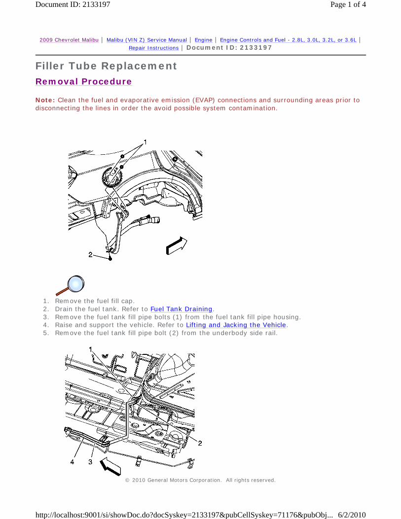
Note: Clean the fuel and evaporative emission (EVAP) connections and surrounding areas prior to disconnecting the lines in order the avoid possible system contamination.
1. Remove the fuel fill cap. 2. Drain the fuel tank. Refer to Fuel Tank Draining. 3. Remove the fuel tank fill pipe bolts (1) from the fuel tank fill pipe housing. 4. Raise and support the vehicle. Refer to Lifting and Jacking the Vehicle. 5. Remove the fuel tank fill pipe bolt (2) from the underbody side rail.
© 2010 General Motors Corporation. All rights reserved.
Page 1 of 4Document ID: 2133197
6/2/2010http://localhost:9001/si/showDoc.do?docSyskey=2133197&pubCellSyskey=71176&pubObj...
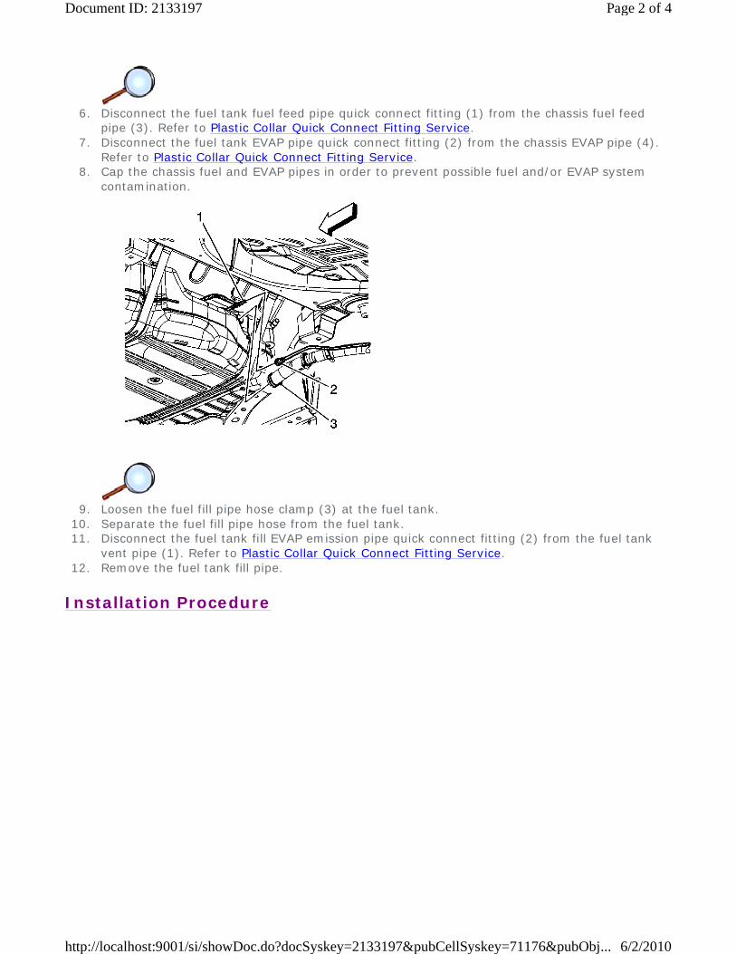
6. Disconnect the fuel tank fuel feed pipe quick connect fitting (1) from the chassis fuel feed
pipe (3). Refer to Plastic Collar Quick Connect Fitting Service. 7. Disconnect the fuel tank EVAP pipe quick connect fitting (2) from the chassis EVAP pipe (4).
Refer to Plastic Collar Quick Connect Fitting Service. 8. Cap the chassis fuel and EVAP pipes in order to prevent possible fuel and/or EVAP system
contamination.
9. Loosen the fuel fill pipe hose clamp (3) at the fuel tank.
10. Separate the fuel fill pipe hose from the fuel tank. 11. Disconnect the fuel tank fill EVAP emission pipe quick connect fitting (2) from the fuel tank
vent pipe (1). Refer to Plastic Collar Quick Connect Fitting Service. 12. Remove the fuel tank fill pipe.
Installation Procedure
Page 2 of 4Document ID: 2133197
6/2/2010http://localhost:9001/si/showDoc.do?docSyskey=2133197&pubCellSyskey=71176&pubObj...
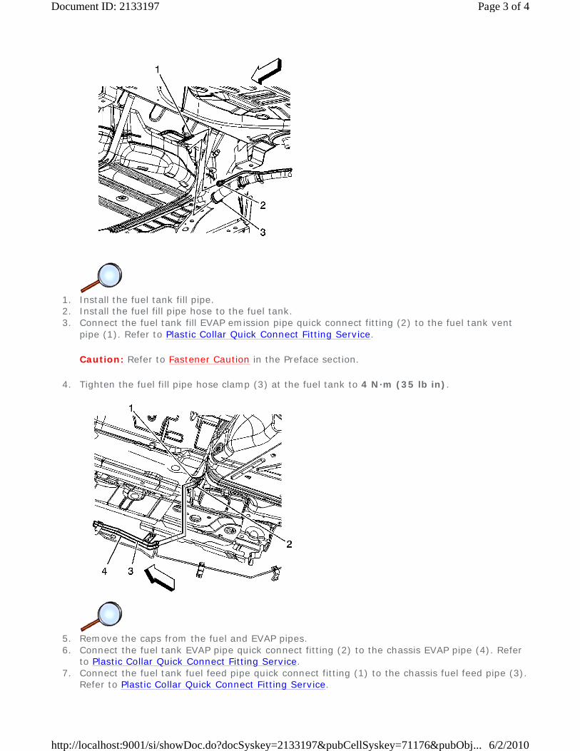
1. Install the fuel tank fill pipe. 2. Install the fuel fill pipe hose to the fuel tank. 3. Connect the fuel tank fill EVAP emission pipe quick connect fitting (2) to the fuel tank vent
pipe (1). Refer to Plastic Collar Quick Connect Fitting Service.
Caution: Refer to Fastener Caution in the Preface section.
4. Tighten the fuel fill pipe hose clamp (3) at the fuel tank to 4 N·m (35 lb in).
5. Remove the caps from the fuel and EVAP pipes. 6. Connect the fuel tank EVAP pipe quick connect fitting (2) to the chassis EVAP pipe (4). Refer
to Plastic Collar Quick Connect Fitting Service. 7. Connect the fuel tank fuel feed pipe quick connect fitting (1) to the chassis fuel feed pipe (3).
Refer to Plastic Collar Quick Connect Fitting Service.
Page 3 of 4Document ID: 2133197
6/2/2010http://localhost:9001/si/showDoc.do?docSyskey=2133197&pubCellSyskey=71176&pubObj...
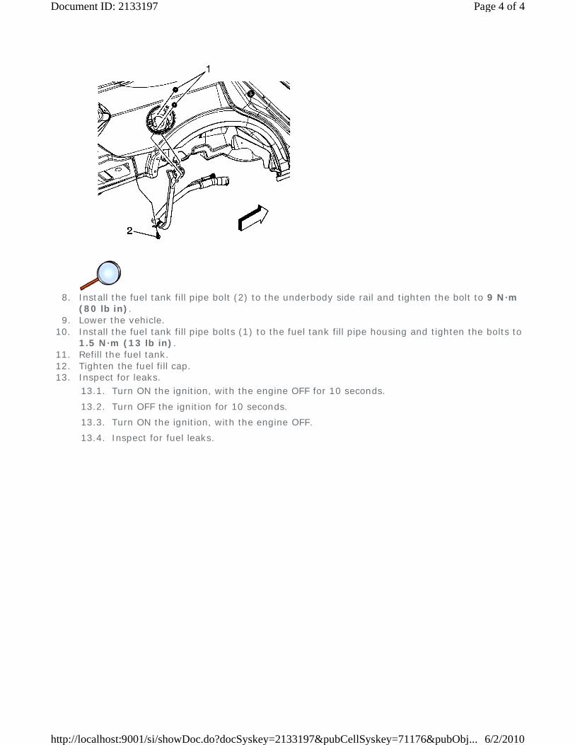
8. Install the fuel tank fill pipe bolt (2) to the underbody side rail and tighten the bolt to 9 N·m
(80 lb in). 9. Lower the vehicle.
10. Install the fuel tank fill pipe bolts (1) to the fuel tank fill pipe housing and tighten the bolts to 1.5 N·m (13 lb in).
11. Refill the fuel tank. 12. Tighten the fuel fill cap. 13. Inspect for leaks.
13.1. Turn ON the ignition, with the engine OFF for 10 seconds.
13.2. Turn OFF the ignition for 10 seconds.
13.3. Turn ON the ignition, with the engine OFF.
13.4. Inspect for fuel leaks.
Page 4 of 4Document ID: 2133197
6/2/2010http://localhost:9001/si/showDoc.do?docSyskey=2133197&pubCellSyskey=71176&pubObj...
2009 Chevrolet Malibu | Malibu (VIN Z) Service Manual | Engine | Engine Controls and Fuel - 2.8L, 3.0L, 3.2L, or 3.6L | Repair Instructions | Document ID: 2049621
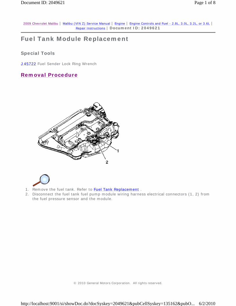
Fuel Tank Module Replacement
Special Tools
J 45722 Fuel Sender Lock Ring Wrench
Removal Procedure
1. Remove the fuel tank. Refer to Fuel Tank Replacement . 2. Disconnect the fuel tank fuel pump module wiring harness electrical connectors (1, 2) from
the fuel pressure sensor and the module.
© 2010 General Motors Corporation. All rights reserved.
Page 1 of 8Document ID: 2049621
6/2/2010http://localhost:9001/si/showDoc.do?docSyskey=2049621&pubCellSyskey=135162&pubO...
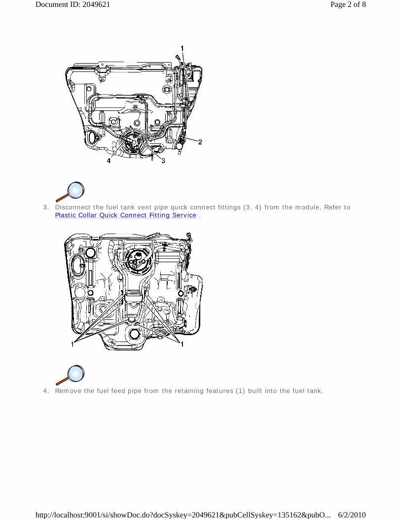
3. Disconnect the fuel tank vent pipe quick connect fittings (3, 4) from the module. Refer to
Plastic Collar Quick Connect Fitting Service .
4. Remove the fuel feed pipe from the retaining features (1) built into the fuel tank.
Page 2 of 8Document ID: 2049621
6/2/2010http://localhost:9001/si/showDoc.do?docSyskey=2049621&pubCellSyskey=135162&pubO...

5. Install the J 45722 to the fuel pump module lock ring.
Notice: Avoid damaging the lock ring. Use only J-45722 to prevent damage to the lock ring.
Notice: Do Not handle the fuel sender assembly by the fuel pipes. The amount of leverage generated by handling the fuel pipes could damage the joints.
Important: Do NOT use impact tools. Significant force will be required to release the lock ring. The use of a hammer and screwdriver is not recommended. Secure the fuel tank in order to prevent fuel tank rotation.
6. Using the J 45722 and a long breaker-bar, rotate the lock ring in a counterclockwise direction in order to unlock the lock ring.
Page 3 of 8Document ID: 2049621
6/2/2010http://localhost:9001/si/showDoc.do?docSyskey=2049621&pubCellSyskey=135162&pubO...
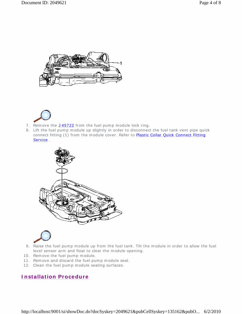
7. Remove the J 45722 from the fuel pump module lock ring. 8. Lift the fuel pump module up slightly in order to disconnect the fuel tank vent pipe quick
connect fitting (1) from the module cover. Refer to Plastic Collar Quick Connect Fitting Service .
9. Raise the fuel pump module up from the fuel tank. Tilt the module in order to allow the fuel
level sensor arm and float to clear the module opening. 10. Remove the fuel pump module. 11. Remove and discard the fuel pump module seal. 12. Clean the fuel pump module sealing surfaces.
Installation Procedure
Page 4 of 8Document ID: 2049621
6/2/2010http://localhost:9001/si/showDoc.do?docSyskey=2049621&pubCellSyskey=135162&pubO...

Caution: Drain the fuel from the fuel sender assembly into an approved container in order to reduce the risk of fire and personal injury. Never store the fuel in an open container.
Important:
1. Clean any contamination from the male pipe ends of the fuel pump module. 2. Place a NEW fuel tank module seal onto the fuel tank. 3. Insert the fuel pump module into the fuel tank allowing the sensor arm and float to clear the
module opening. 4. Lower the module down into the fuel tank until the fuel tank vent pipe quick connect fitting
can be connected.
• Some lock rings were manufactured with "DO NOT REUSE" stamped into them. These lock rings may be reused if they are not damaged or warped.
• Inspect the lock ring for damage due to improper removal or installation procedures. If damage is found, install a NEW fuel pump module.
• Inspect the lock ring for flatness as best as possible. If the lock ring is warped, replace the fuel pump module.
Page 5 of 8Document ID: 2049621
6/2/2010http://localhost:9001/si/showDoc.do?docSyskey=2049621&pubCellSyskey=135162&pubO...

5. Connect the fuel tank vent pipe quick connect fitting (1) at the module cover. Refer to Plastic
Collar Quick Connect Fitting Service . 6. Press the fuel tank module downward.
7. Install the J 45722 to the fuel pump module lock ring.
Page 6 of 8Document ID: 2049621
6/2/2010http://localhost:9001/si/showDoc.do?docSyskey=2049621&pubCellSyskey=135162&pubO...
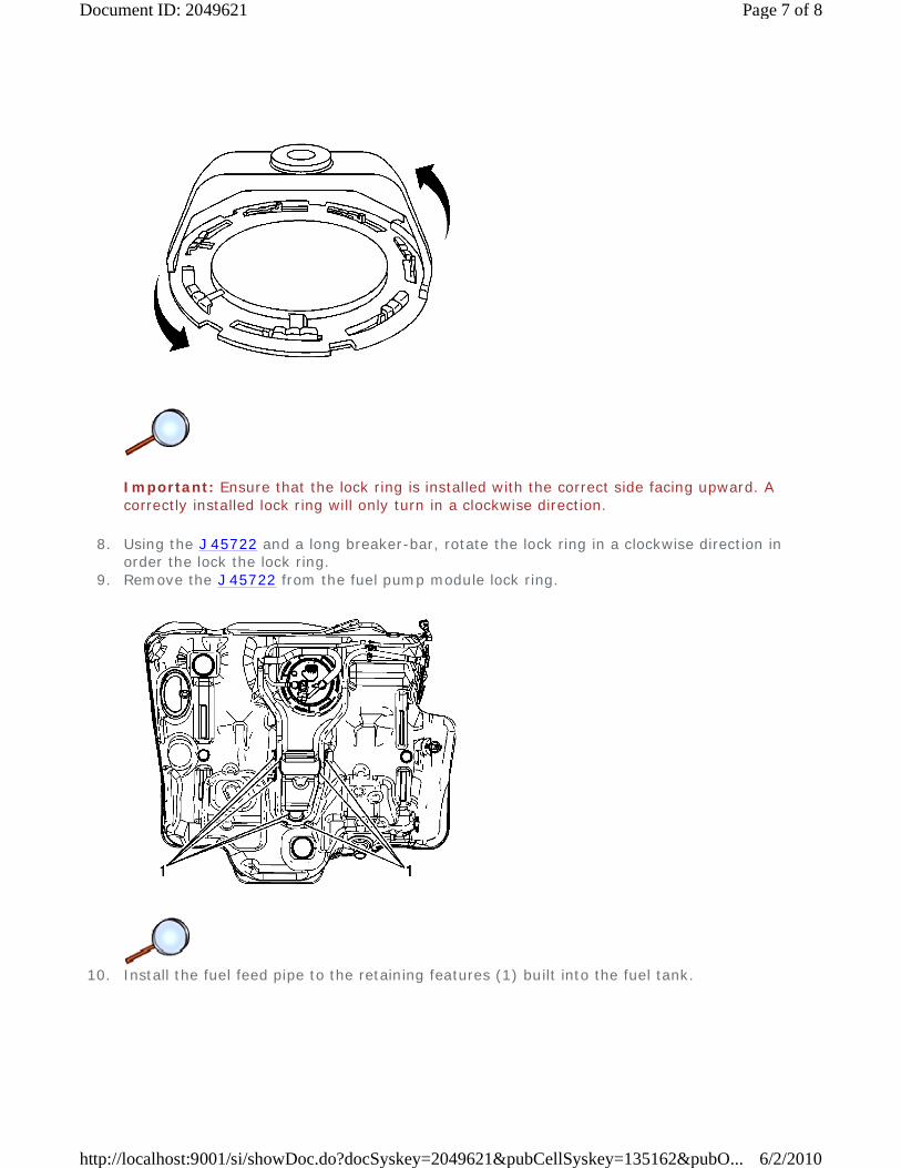
Important: Ensure that the lock ring is installed with the correct side facing upward. A correctly installed lock ring will only turn in a clockwise direction.
8. Using the J 45722 and a long breaker-bar, rotate the lock ring in a clockwise direction in order the lock the lock ring.
9. Remove the J 45722 from the fuel pump module lock ring.
10. Install the fuel feed pipe to the retaining features (1) built into the fuel tank.
Page 7 of 8Document ID: 2049621
6/2/2010http://localhost:9001/si/showDoc.do?docSyskey=2049621&pubCellSyskey=135162&pubO...
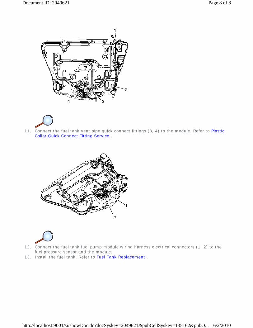
11. Connect the fuel tank vent pipe quick connect fittings (3, 4) to the module. Refer to Plastic
Collar Quick Connect Fitting Service .
12. Connect the fuel tank fuel pump module wiring harness electrical connectors (1, 2) to the
fuel pressure sensor and the module. 13. Install the fuel tank. Refer to Fuel Tank Replacement .
Page 8 of 8Document ID: 2049621
6/2/2010http://localhost:9001/si/showDoc.do?docSyskey=2049621&pubCellSyskey=135162&pubO...
2009 Chevrolet Malibu | Malibu (VIN Z) Service Manual | Engine | Engine Controls and Fuel - 2.8L, 3.0L, 3.2L, or 3.6L | Repair Instructions | Document ID: 1838949
Fuel Level Sensor Replacement
Removal Procedure
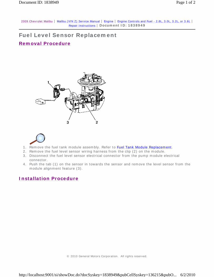
1. Remove the fuel tank module assembly. Refer to Fuel Tank Module Replacement. 2. Remove the fuel level sensor wiring harness from the clip (2) on the module. 3. Disconnect the fuel level sensor electrical connector from the pump module electrical
connector. 4. Push the tab (1) on the sensor in towards the sensor and remove the level sensor from the
module alignment feature (3).
Installation Procedure
© 2010 General Motors Corporation. All rights reserved.
Page 1 of 2Document ID: 1838949
6/2/2010http://localhost:9001/si/showDoc.do?docSyskey=1838949&pubCellSyskey=136215&pubO...

1. Connect the fuel level sensor electrical connector to the pump module electrical connector. 2. Align the tab opening on the rear of the fuel level senor with the module alignment feature
(3). 3. Press the tab (1) on the sensor out away from the sensor securing the sensor to the module. 4. Install the fuel level sensor wiring harness to the clip (2) on the module. 5. Install the fuel tank module assembly. Refer to Fuel Tank Module Replacement.
Page 2 of 2Document ID: 1838949
6/2/2010http://localhost:9001/si/showDoc.do?docSyskey=1838949&pubCellSyskey=136215&pubO...

2009 Chevrolet Malibu | Malibu (VIN Z) Service Manual | Engine | Engine Controls and Fuel - 2.8L, 3.0L, 3.2L, or 3.6L | Repair Instructions | Document ID: 2133202
Fuel Hose/Pipes Replacement - Chassis
Removal Procedure
1. Relieve the fuel system pressure. Refer to Fuel Pressure Relief. 2. Remove the fuel injector sight shield. Refer to Fuel Injector Sight Shield Replacement. 3. Remove the fuel feed pipe clip nut (2) from the intake manifold stud. 4. Disconnect the fuel feed pipe (1) quick connect fitting from the fuel rail. Refer to Metal Collar
Quick Connect Fitting Service. 5. Disconnect the evaporative emission (EVAP) pipe (3) quick connect fitting from the EVAP
purge solenoid. Refer to Metal Collar Quick Connect Fitting Service. 6. Cap the fuel rail pipe and the EVAP purge solenoid in order to prevent possible fuel and/or
EVAP system contamination.
© 2010 General Motors Corporation. All rights reserved.
Page 1 of 5Document ID: 2133202
6/2/2010http://localhost:9001/si/showDoc.do?docSyskey=2133202&pubCellSyskey=81126&pubObj...
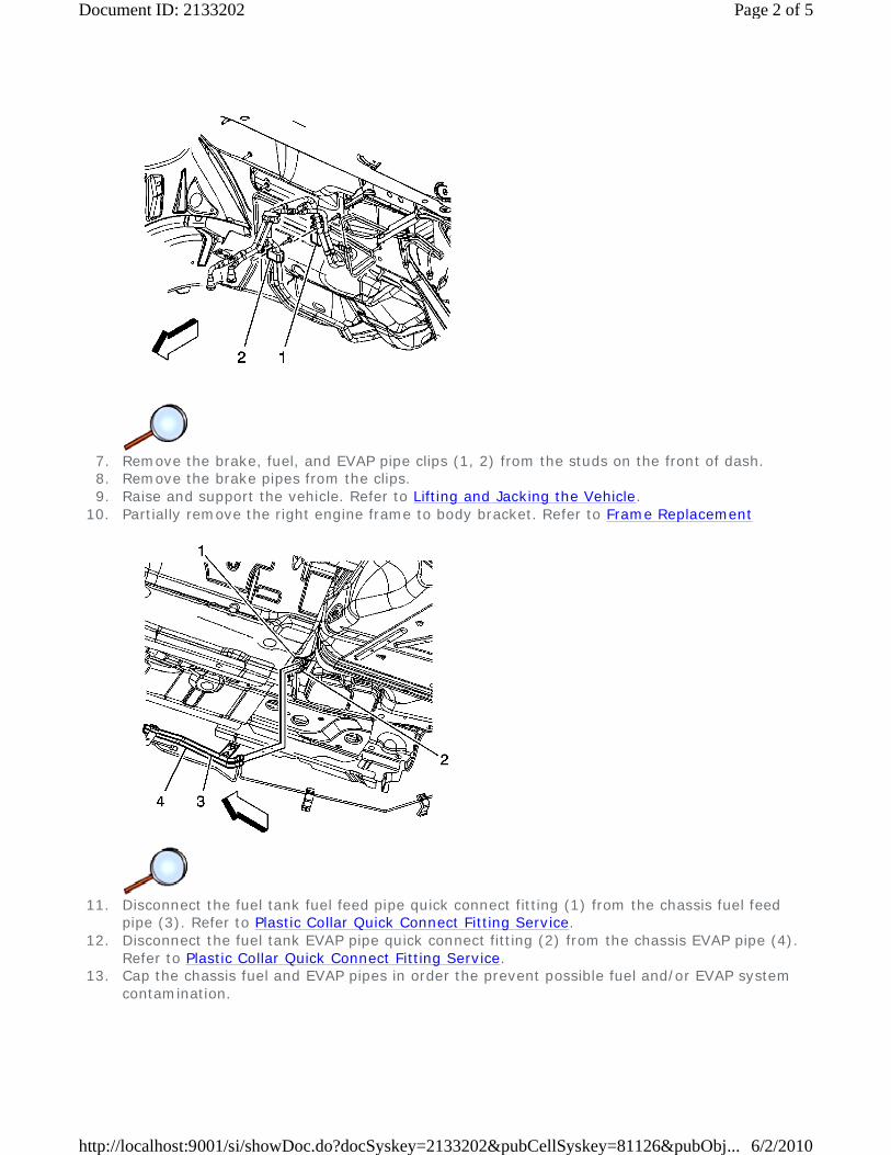
7. Remove the brake, fuel, and EVAP pipe clips (1, 2) from the studs on the front of dash. 8. Remove the brake pipes from the clips. 9. Raise and support the vehicle. Refer to Lifting and Jacking the Vehicle.
10. Partially remove the right engine frame to body bracket. Refer to Frame Replacement
11. Disconnect the fuel tank fuel feed pipe quick connect fitting (1) from the chassis fuel feed
pipe (3). Refer to Plastic Collar Quick Connect Fitting Service. 12. Disconnect the fuel tank EVAP pipe quick connect fitting (2) from the chassis EVAP pipe (4).
Refer to Plastic Collar Quick Connect Fitting Service. 13. Cap the chassis fuel and EVAP pipes in order the prevent possible fuel and/or EVAP system
contamination.
Page 2 of 5Document ID: 2133202
6/2/2010http://localhost:9001/si/showDoc.do?docSyskey=2133202&pubCellSyskey=81126&pubObj...
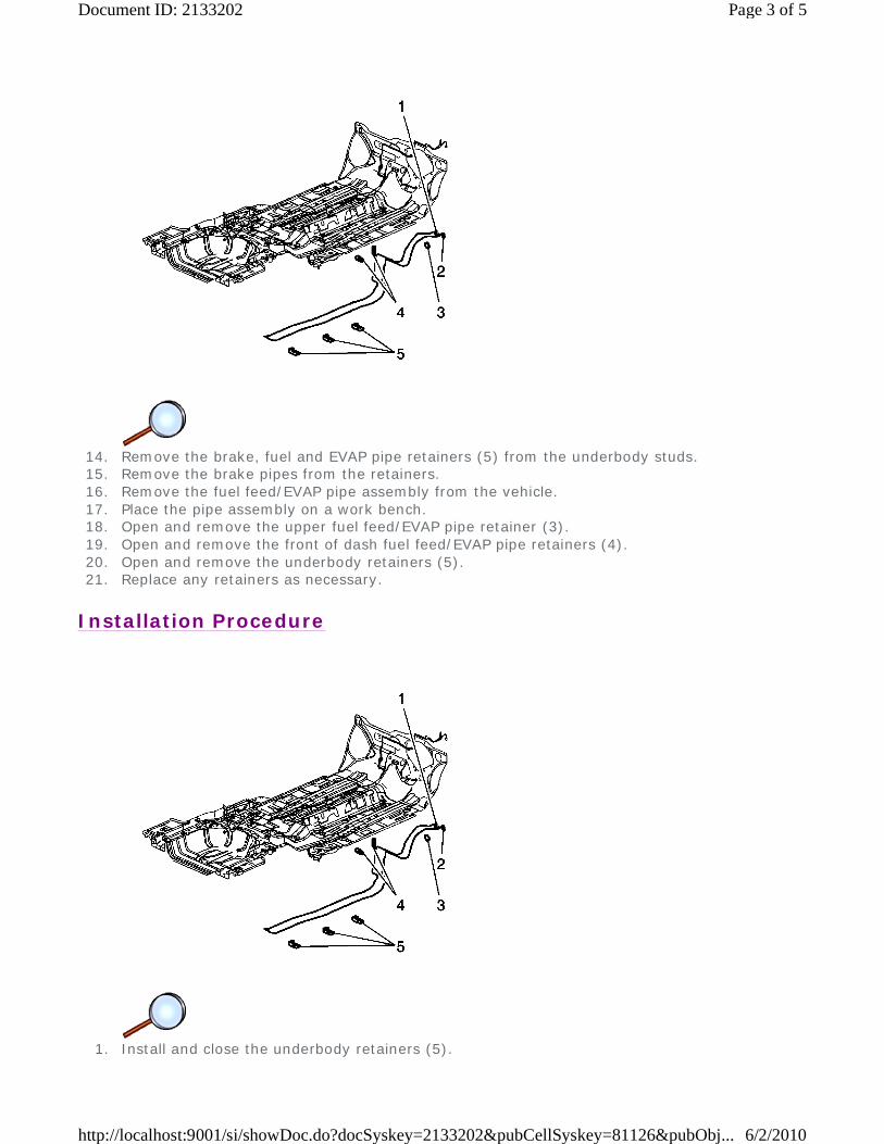
14. Remove the brake, fuel and EVAP pipe retainers (5) from the underbody studs. 15. Remove the brake pipes from the retainers. 16. Remove the fuel feed/EVAP pipe assembly from the vehicle. 17. Place the pipe assembly on a work bench. 18. Open and remove the upper fuel feed/EVAP pipe retainer (3). 19. Open and remove the front of dash fuel feed/EVAP pipe retainers (4). 20. Open and remove the underbody retainers (5). 21. Replace any retainers as necessary.
Installation Procedure
1. Install and close the underbody retainers (5).
Page 3 of 5Document ID: 2133202
6/2/2010http://localhost:9001/si/showDoc.do?docSyskey=2133202&pubCellSyskey=81126&pubObj...
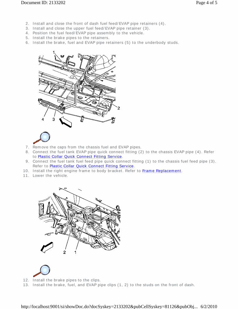
2. Install and close the front of dash fuel feed/EVAP pipe retainers (4). 3. Install and close the upper fuel feed/EVAP pipe retainer (3). 4. Position the fuel feed/EVAP pipe assembly to the vehicle. 5. Install the brake pipes to the retainers. 6. Install the brake, fuel and EVAP pipe retainers (5) to the underbody studs.
7. Remove the caps from the chassis fuel and EVAP pipes. 8. Connect the fuel tank EVAP pipe quick connect fitting (2) to the chassis EVAP pipe (4). Refer
to Plastic Collar Quick Connect Fitting Service. 9. Connect the fuel tank fuel feed pipe quick connect fitting (1) to the chassis fuel feed pipe (3).
Refer to Plastic Collar Quick Connect Fitting Service. 10. Install the right engine frame to body bracket. Refer to Frame Replacement. 11. Lower the vehicle.
12. Install the brake pipes to the clips. 13. Install the brake, fuel, and EVAP pipe clips (1, 2) to the studs on the front of dash.
Page 4 of 5Document ID: 2133202
6/2/2010http://localhost:9001/si/showDoc.do?docSyskey=2133202&pubCellSyskey=81126&pubObj...
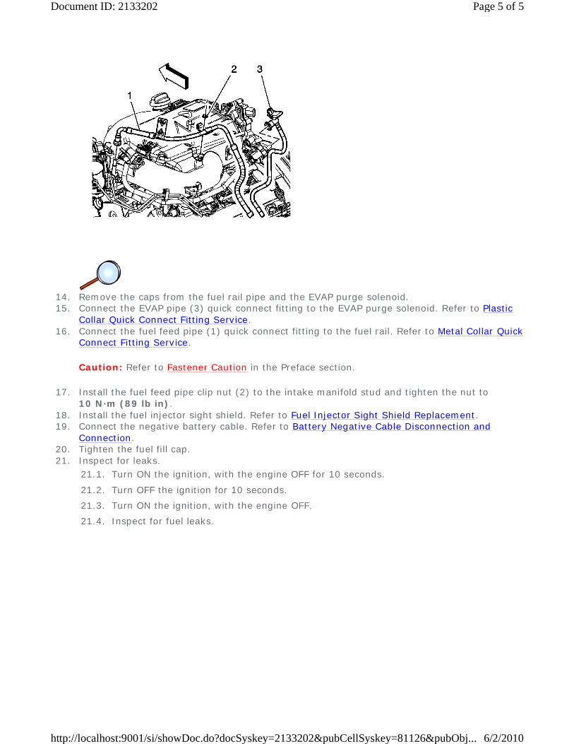
14. Remove the caps from the fuel rail pipe and the EVAP purge solenoid. 15. Connect the EVAP pipe (3) quick connect fitting to the EVAP purge solenoid. Refer to Plastic
Collar Quick Connect Fitting Service. 16. Connect the fuel feed pipe (1) quick connect fitting to the fuel rail. Refer to Metal Collar Quick
Connect Fitting Service.
Caution: Refer to Fastener Caution in the Preface section.
17. Install the fuel feed pipe clip nut (2) to the intake manifold stud and tighten the nut to 10 N·m (89 lb in).
18. Install the fuel injector sight shield. Refer to Fuel Injector Sight Shield Replacement. 19. Connect the negative battery cable. Refer to Battery Negative Cable Disconnection and
Connection. 20. Tighten the fuel fill cap. 21. Inspect for leaks.
21.1. Turn ON the ignition, with the engine OFF for 10 seconds.
21.2. Turn OFF the ignition for 10 seconds.
21.3. Turn ON the ignition, with the engine OFF.
21.4. Inspect for fuel leaks.
Page 5 of 5Document ID: 2133202
6/2/2010http://localhost:9001/si/showDoc.do?docSyskey=2133202&pubCellSyskey=81126&pubObj...
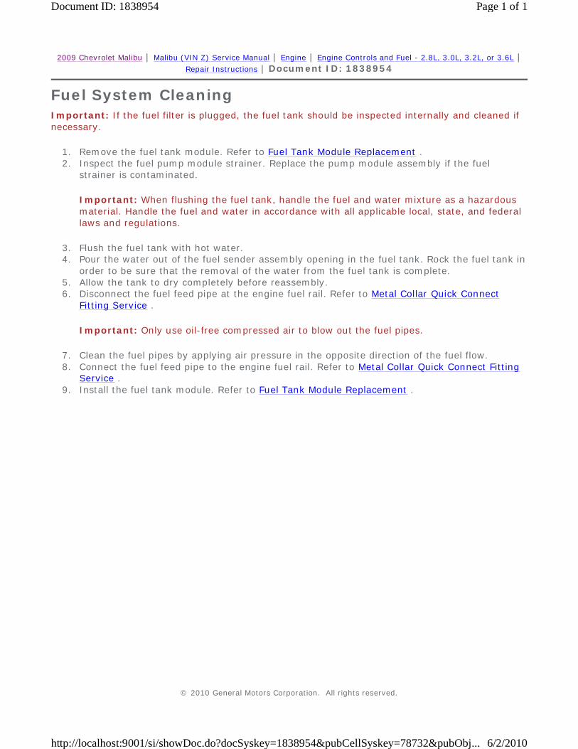
2009 Chevrolet Malibu | Malibu (VIN Z) Service Manual | Engine | Engine Controls and Fuel - 2.8L, 3.0L, 3.2L, or 3.6L | Repair Instructions | Document ID: 1838954
Fuel System Cleaning Important: If the fuel filter is plugged, the fuel tank should be inspected internally and cleaned if necessary.
1. Remove the fuel tank module. Refer to Fuel Tank Module Replacement . 2. Inspect the fuel pump module strainer. Replace the pump module assembly if the fuel
strainer is contaminated.
Important: When flushing the fuel tank, handle the fuel and water mixture as a hazardous material. Handle the fuel and water in accordance with all applicable local, state, and federal laws and regulations.
3. Flush the fuel tank with hot water. 4. Pour the water out of the fuel sender assembly opening in the fuel tank. Rock the fuel tank in
order to be sure that the removal of the water from the fuel tank is complete. 5. Allow the tank to dry completely before reassembly. 6. Disconnect the fuel feed pipe at the engine fuel rail. Refer to Metal Collar Quick Connect
Fitting Service .
Important: Only use oil-free compressed air to blow out the fuel pipes.
7. Clean the fuel pipes by applying air pressure in the opposite direction of the fuel flow. 8. Connect the fuel feed pipe to the engine fuel rail. Refer to Metal Collar Quick Connect Fitting
Service . 9. Install the fuel tank module. Refer to Fuel Tank Module Replacement .
© 2010 General Motors Corporation. All rights reserved.
Page 1 of 1Document ID: 1838954
6/2/2010http://localhost:9001/si/showDoc.do?docSyskey=1838954&pubCellSyskey=78732&pubObj...
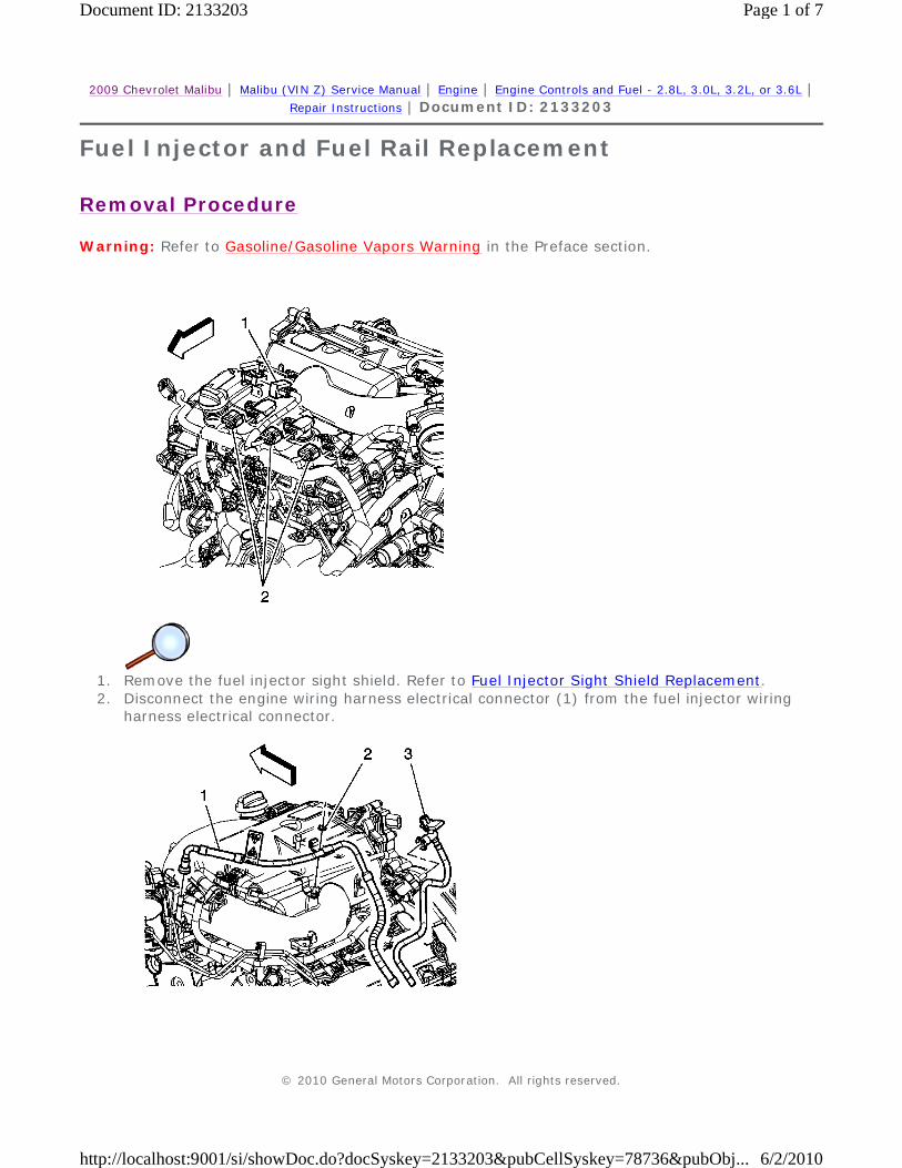
2009 Chevrolet Malibu | Malibu (VIN Z) Service Manual | Engine | Engine Controls and Fuel - 2.8L, 3.0L, 3.2L, or 3.6L | Repair Instructions | Document ID: 2133203
Fuel Injector and Fuel Rail Replacement
Removal Procedure
Warning: Refer to Gasoline/Gasoline Vapors Warning in the Preface section.
1. Remove the fuel injector sight shield. Refer to Fuel Injector Sight Shield Replacement. 2. Disconnect the engine wiring harness electrical connector (1) from the fuel injector wiring
harness electrical connector.
© 2010 General Motors Corporation. All rights reserved.
Page 1 of 7Document ID: 2133203
6/2/2010http://localhost:9001/si/showDoc.do?docSyskey=2133203&pubCellSyskey=78736&pubObj...
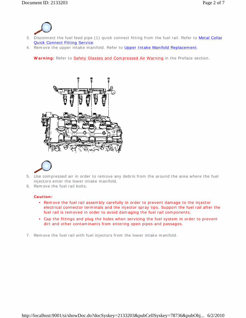
3. Disconnect the fuel feed pipe (1) quick connect fitting from the fuel rail. Refer to Metal Collar
Quick Connect Fitting Service. 4. Remove the upper intake manifold. Refer to Upper Intake Manifold Replacement.
Warning: Refer to Safety Glasses and Compressed Air Warning in the Preface section.
5. Use compressed air in order to remove any debris from the around the area where the fuel
injectors enter the lower intake manifold. 6. Remove the fuel rail bolts.
Caution:
7. Remove the fuel rail with fuel injectors from the lower intake manifold.
• Remove the fuel rail assembly carefully in order to prevent damage to the injector electrical connector terminals and the injector spray tips. Support the fuel rail after the fuel rail is removed in order to avoid damaging the fuel rail components.
• Cap the fittings and plug the holes when servicing the fuel system in order to prevent dirt and other contaminants from entering open pipes and passages.
Page 2 of 7Document ID: 2133203
6/2/2010http://localhost:9001/si/showDoc.do?docSyskey=2133203&pubCellSyskey=78736&pubObj...
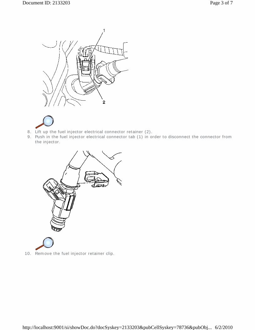
8. Lift up the fuel injector electrical connector retainer (2). 9. Push in the fuel injector electrical connector tab (1) in order to disconnect the connector from
the injector.
10. Remove the fuel injector retainer clip.
Page 3 of 7Document ID: 2133203
6/2/2010http://localhost:9001/si/showDoc.do?docSyskey=2133203&pubCellSyskey=78736&pubObj...
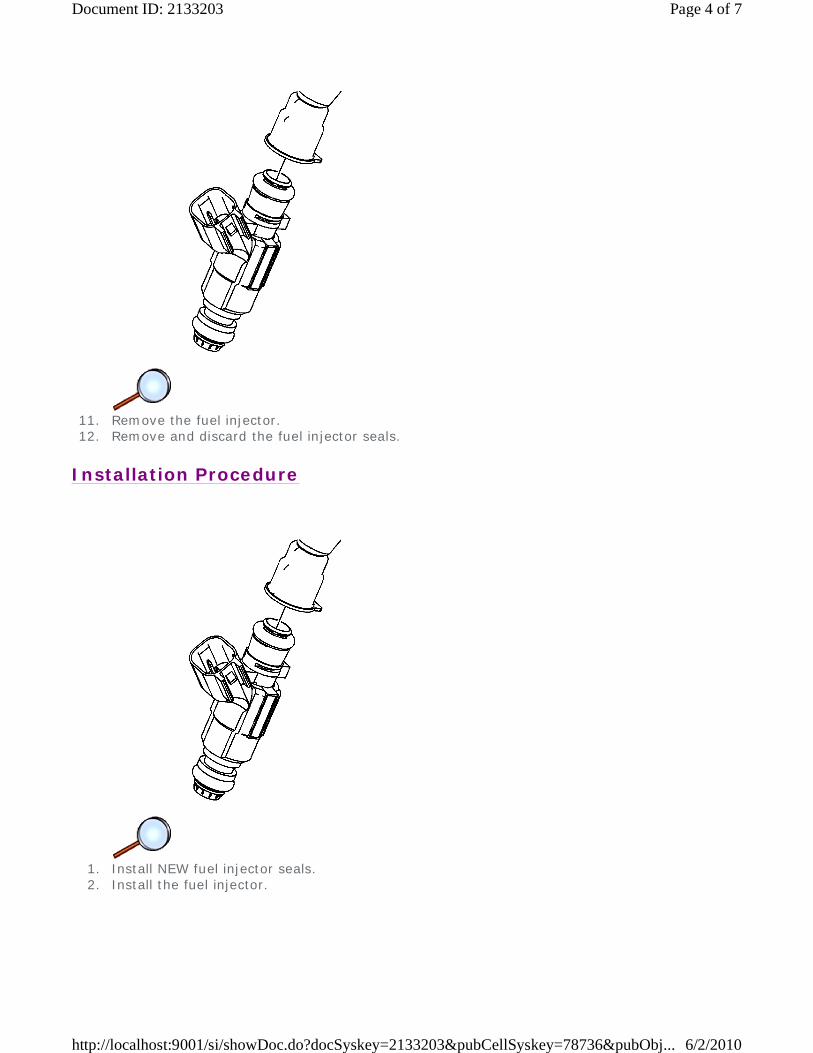
11. Remove the fuel injector. 12. Remove and discard the fuel injector seals.
Installation Procedure
1. Install NEW fuel injector seals. 2. Install the fuel injector.
Page 4 of 7Document ID: 2133203
6/2/2010http://localhost:9001/si/showDoc.do?docSyskey=2133203&pubCellSyskey=78736&pubObj...

3. Install the fuel injector retainer clip.
4. Install the fuel injector electrical connector. 5. Push down on the fuel injector electrical connector retainer (2), securing the electrical
connector.
Page 5 of 7Document ID: 2133203
6/2/2010http://localhost:9001/si/showDoc.do?docSyskey=2133203&pubCellSyskey=78736&pubObj...
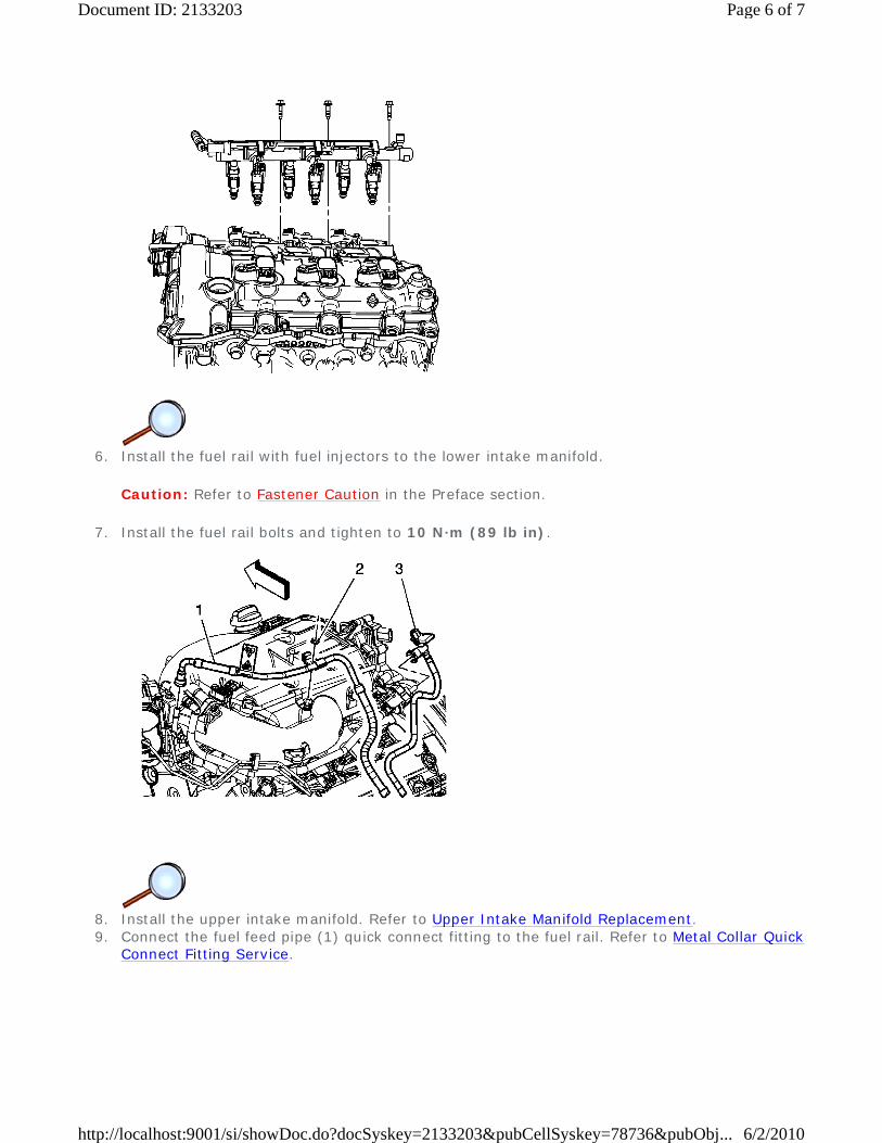
6. Install the fuel rail with fuel injectors to the lower intake manifold.
Caution: Refer to Fastener Caution in the Preface section.
7. Install the fuel rail bolts and tighten to 10 N·m (89 lb in).
8. Install the upper intake manifold. Refer to Upper Intake Manifold Replacement. 9. Connect the fuel feed pipe (1) quick connect fitting to the fuel rail. Refer to Metal Collar Quick
Connect Fitting Service.
Page 6 of 7Document ID: 2133203
6/2/2010http://localhost:9001/si/showDoc.do?docSyskey=2133203&pubCellSyskey=78736&pubObj...
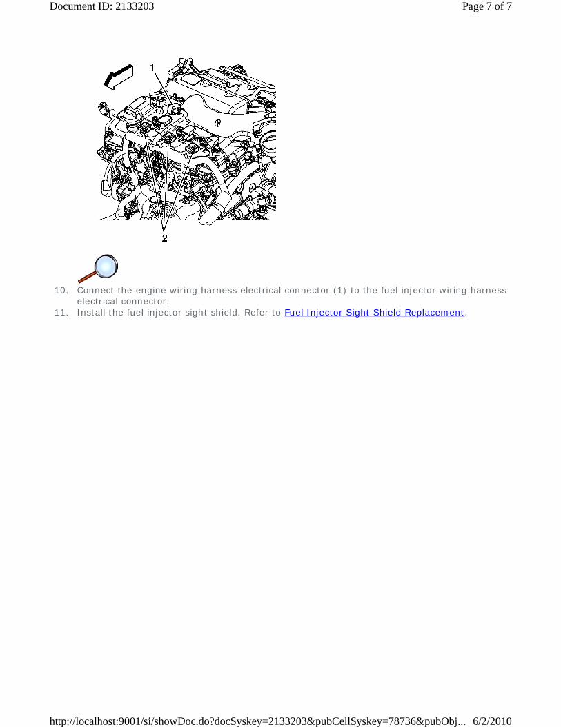
10. Connect the engine wiring harness electrical connector (1) to the fuel injector wiring harness
electrical connector. 11. Install the fuel injector sight shield. Refer to Fuel Injector Sight Shield Replacement.
Page 7 of 7Document ID: 2133203
6/2/2010http://localhost:9001/si/showDoc.do?docSyskey=2133203&pubCellSyskey=78736&pubObj...
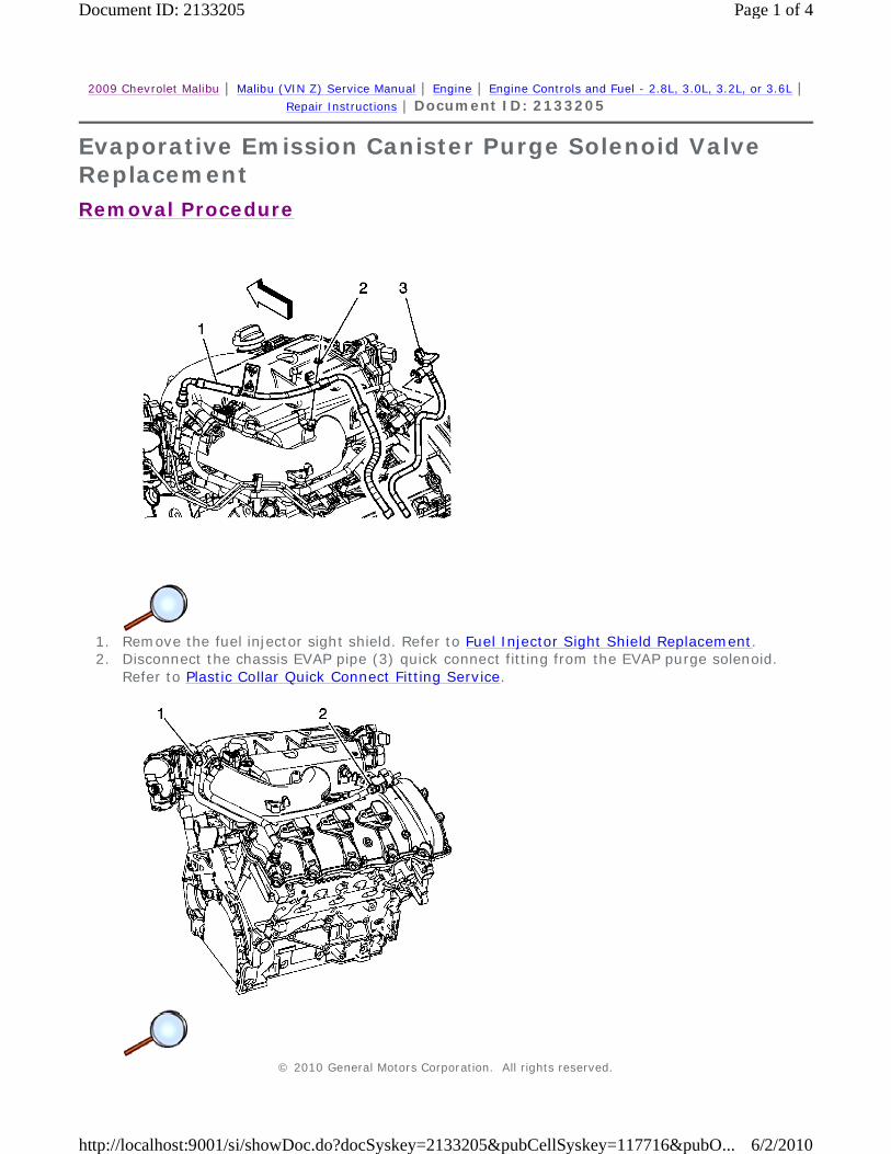
2009 Chevrolet Malibu | Malibu (VIN Z) Service Manual | Engine | Engine Controls and Fuel - 2.8L, 3.0L, 3.2L, or 3.6L | Repair Instructions | Document ID: 2133205
Evaporative Emission Canister Purge Solenoid Valve Replacement
Removal Procedure
1. Remove the fuel injector sight shield. Refer to Fuel Injector Sight Shield Replacement. 2. Disconnect the chassis EVAP pipe (3) quick connect fitting from the EVAP purge solenoid.
Refer to Plastic Collar Quick Connect Fitting Service.
© 2010 General Motors Corporation. All rights reserved.
Page 1 of 4Document ID: 2133205
6/2/2010http://localhost:9001/si/showDoc.do?docSyskey=2133205&pubCellSyskey=117716&pubO...
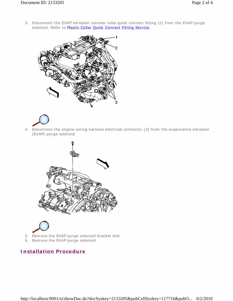
3. Disconnect the EVAP emission canister tube quick connect fitting (2) from the EVAP purge solenoid. Refer to Plastic Collar Quick Connect Fitting Service.
4. Disconnect the engine wiring harness electrical connector (2) from the evaporative emission
(EVAP) purge solenoid.
5. Remove the EVAP purge solenoid bracket bolt. 6. Remove the EVAP purge solenoid.
Installation Procedure
Page 2 of 4Document ID: 2133205
6/2/2010http://localhost:9001/si/showDoc.do?docSyskey=2133205&pubCellSyskey=117716&pubO...
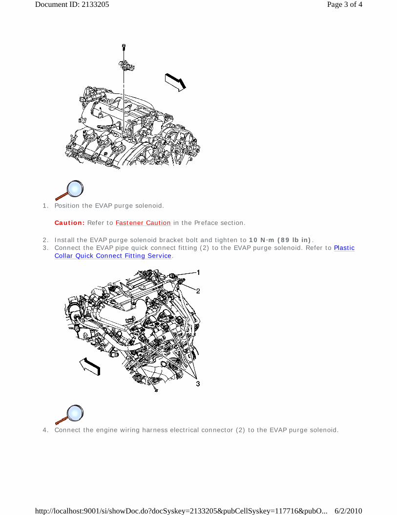
1. Position the EVAP purge solenoid.
Caution: Refer to Fastener Caution in the Preface section.
2. Install the EVAP purge solenoid bracket bolt and tighten to 10 N·m (89 lb in). 3. Connect the EVAP pipe quick connect fitting (2) to the EVAP purge solenoid. Refer to Plastic
Collar Quick Connect Fitting Service.
4. Connect the engine wiring harness electrical connector (2) to the EVAP purge solenoid.
Page 3 of 4Document ID: 2133205
6/2/2010http://localhost:9001/si/showDoc.do?docSyskey=2133205&pubCellSyskey=117716&pubO...
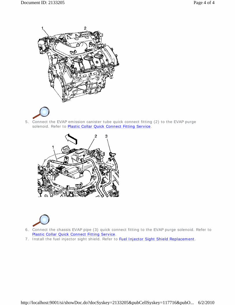
5. Connect the EVAP emission canister tube quick connect fitting (2) to the EVAP purge
solenoid. Refer to Plastic Collar Quick Connect Fitting Service.
6. Connect the chassis EVAP pipe (3) quick connect fitting to the EVAP purge solenoid. Refer to
Plastic Collar Quick Connect Fitting Service. 7. Install the fuel injector sight shield. Refer to Fuel Injector Sight Shield Replacement.
Page 4 of 4Document ID: 2133205
6/2/2010http://localhost:9001/si/showDoc.do?docSyskey=2133205&pubCellSyskey=117716&pubO...
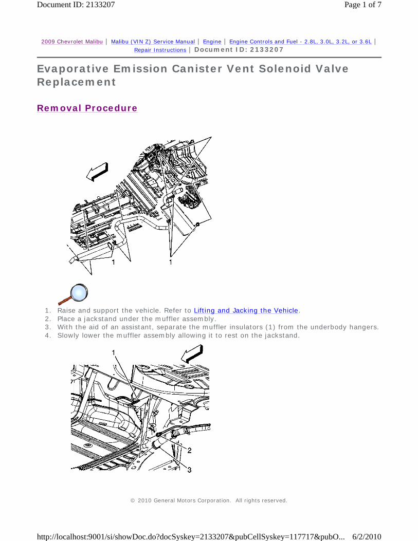
2009 Chevrolet Malibu | Malibu (VIN Z) Service Manual | Engine | Engine Controls and Fuel - 2.8L, 3.0L, 3.2L, or 3.6L | Repair Instructions | Document ID: 2133207
Evaporative Emission Canister Vent Solenoid Valve Replacement
Removal Procedure
1. Raise and support the vehicle. Refer to Lifting and Jacking the Vehicle. 2. Place a jackstand under the muffler assembly. 3. With the aid of an assistant, separate the muffler insulators (1) from the underbody hangers. 4. Slowly lower the muffler assembly allowing it to rest on the jackstand.
© 2010 General Motors Corporation. All rights reserved.
Page 1 of 7Document ID: 2133207
6/2/2010http://localhost:9001/si/showDoc.do?docSyskey=2133207&pubCellSyskey=117717&pubO...
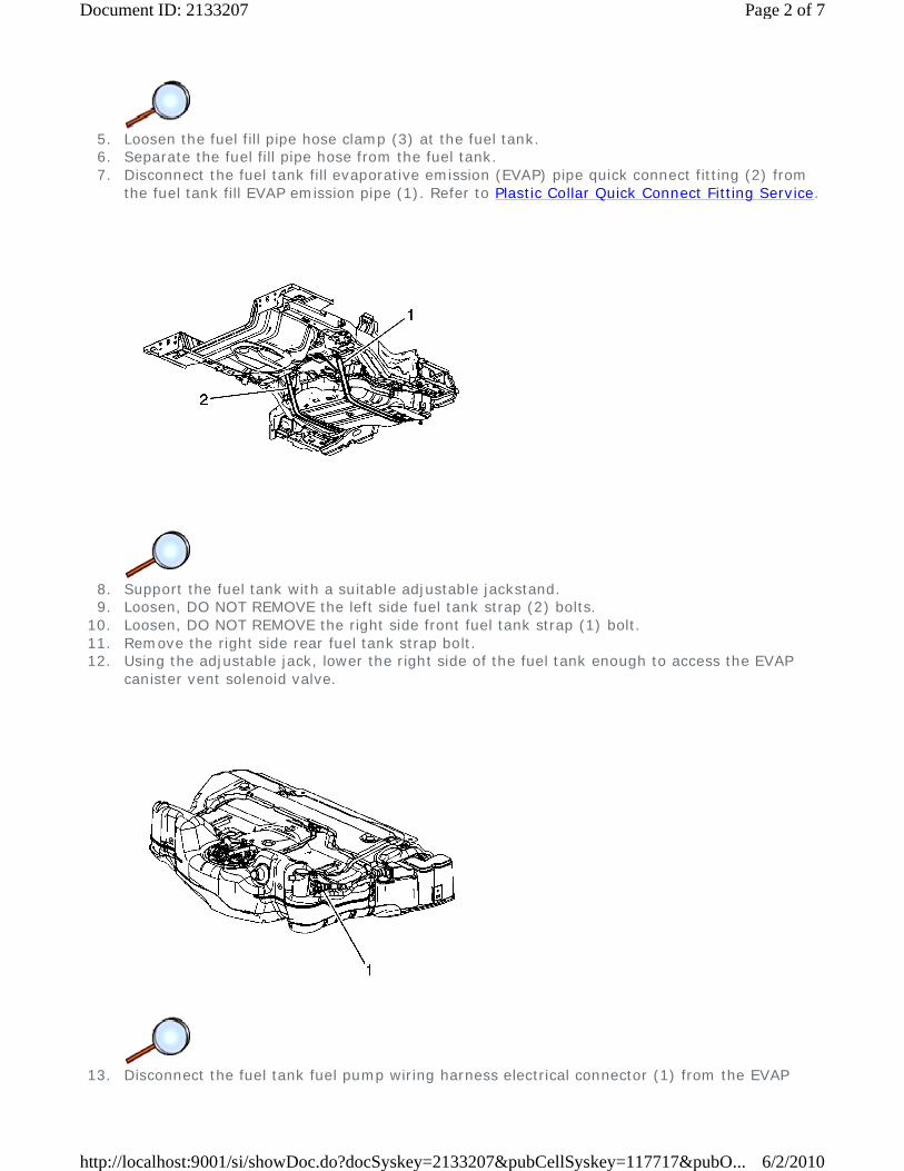
5. Loosen the fuel fill pipe hose clamp (3) at the fuel tank. 6. Separate the fuel fill pipe hose from the fuel tank. 7. Disconnect the fuel tank fill evaporative emission (EVAP) pipe quick connect fitting (2) from
the fuel tank fill EVAP emission pipe (1). Refer to Plastic Collar Quick Connect Fitting Service.
8. Support the fuel tank with a suitable adjustable jackstand. 9. Loosen, DO NOT REMOVE the left side fuel tank strap (2) bolts.
10. Loosen, DO NOT REMOVE the right side front fuel tank strap (1) bolt. 11. Remove the right side rear fuel tank strap bolt. 12. Using the adjustable jack, lower the right side of the fuel tank enough to access the EVAP
canister vent solenoid valve.
13. Disconnect the fuel tank fuel pump wiring harness electrical connector (1) from the EVAP
Page 2 of 7Document ID: 2133207
6/2/2010http://localhost:9001/si/showDoc.do?docSyskey=2133207&pubCellSyskey=117717&pubO...
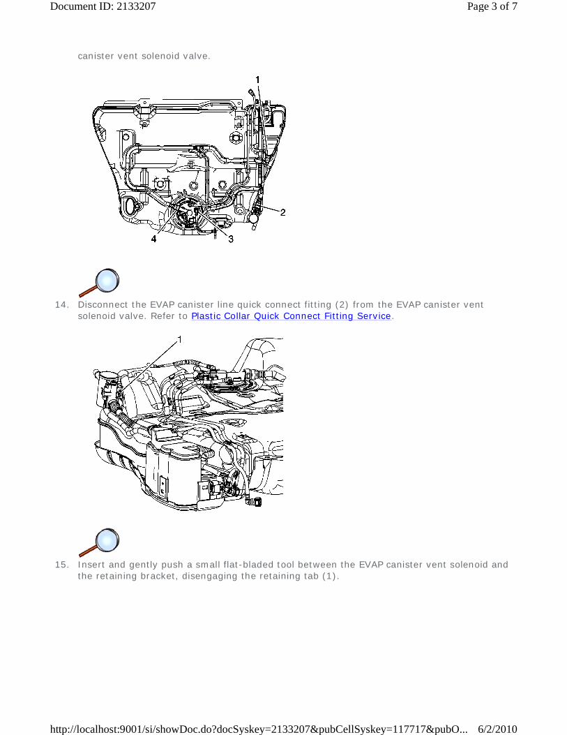
canister vent solenoid valve.
14. Disconnect the EVAP canister line quick connect fitting (2) from the EVAP canister vent
solenoid valve. Refer to Plastic Collar Quick Connect Fitting Service.
15. Insert and gently push a small flat-bladed tool between the EVAP canister vent solenoid and
the retaining bracket, disengaging the retaining tab (1).
Page 3 of 7Document ID: 2133207
6/2/2010http://localhost:9001/si/showDoc.do?docSyskey=2133207&pubCellSyskey=117717&pubO...

16. Slide the EVAP canister vent solenoid valve toward the rear of the vehicle.
Installation Procedure
1. Slide the EVAP canister vent solenoid valve onto the bracket on the fuel tank.
Page 4 of 7Document ID: 2133207
6/2/2010http://localhost:9001/si/showDoc.do?docSyskey=2133207&pubCellSyskey=117717&pubO...
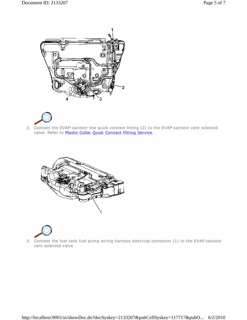
2. Connect the EVAP canister line quick connect fitting (2) to the EVAP canister vent solenoid
valve. Refer to Plastic Collar Quick Connect Fitting Service.
3. Connect the fuel tank fuel pump wiring harness electrical connector (1) to the EVAP canister
vent solenoid valve.
Page 5 of 7Document ID: 2133207
6/2/2010http://localhost:9001/si/showDoc.do?docSyskey=2133207&pubCellSyskey=117717&pubO...
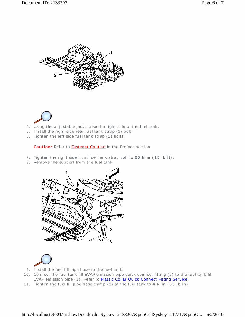
4. Using the adjustable jack, raise the right side of the fuel tank. 5. Install the right side rear fuel tank strap (1) bolt. 6. Tighten the left side fuel tank strap (2) bolts.
Caution: Refer to Fastener Caution in the Preface section.
7. Tighten the right side front fuel tank strap bolt to 20 N·m (15 lb ft). 8. Remove the support from the fuel tank.
9. Install the fuel fill pipe hose to the fuel tank.
10. Connect the fuel tank fill EVAP emission pipe quick connect fitting (2) to the fuel tank fill EVAP emission pipe (1). Refer to Plastic Collar Quick Connect Fitting Service.
11. Tighten the fuel fill pipe hose clamp (3) at the fuel tank to 4 N·m (35 lb in).
Page 6 of 7Document ID: 2133207
6/2/2010http://localhost:9001/si/showDoc.do?docSyskey=2133207&pubCellSyskey=117717&pubO...
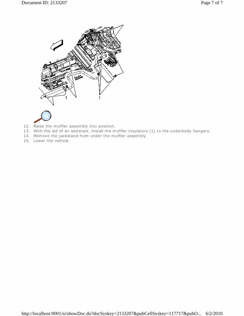
12. Raise the muffler assembly into position. 13. With the aid of an assistant, install the muffler insulators (1) to the underbody hangers. 14. Remove the jackstand from under the muffler assembly. 15. Lower the vehicle.
Page 7 of 7Document ID: 2133207
6/2/2010http://localhost:9001/si/showDoc.do?docSyskey=2133207&pubCellSyskey=117717&pubO...
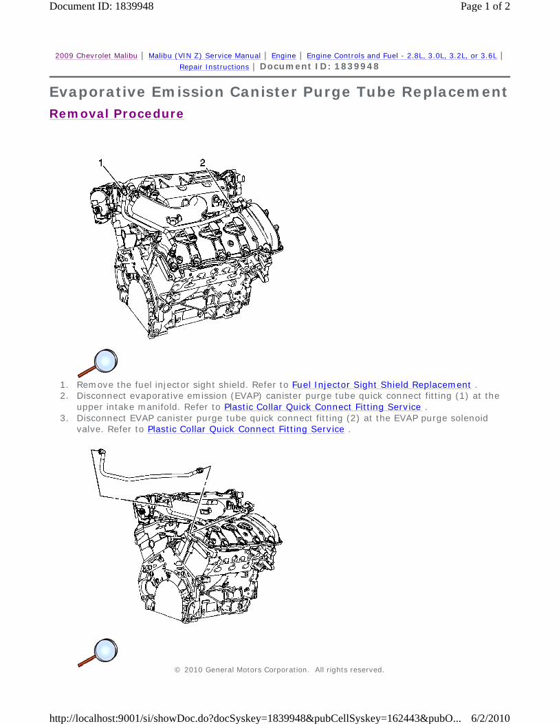
2009 Chevrolet Malibu | Malibu (VIN Z) Service Manual | Engine | Engine Controls and Fuel - 2.8L, 3.0L, 3.2L, or 3.6L | Repair Instructions | Document ID: 1839948
Evaporative Emission Canister Purge Tube Replacement
Removal Procedure
1. Remove the fuel injector sight shield. Refer to Fuel Injector Sight Shield Replacement . 2. Disconnect evaporative emission (EVAP) canister purge tube quick connect fitting (1) at the
upper intake manifold. Refer to Plastic Collar Quick Connect Fitting Service . 3. Disconnect EVAP canister purge tube quick connect fitting (2) at the EVAP purge solenoid
valve. Refer to Plastic Collar Quick Connect Fitting Service .
© 2010 General Motors Corporation. All rights reserved.
Page 1 of 2Document ID: 1839948
6/2/2010http://localhost:9001/si/showDoc.do?docSyskey=1839948&pubCellSyskey=162443&pubO...

4. Remove the EVAP canister purge tube from under the positive crankcase ventilation (PCV) tube and from the vehicle.
Installation Procedure
1. Install the EVAP canister purge tube to the vehicle and route the purge tube under the PCV
tube.
2. Connect EVAP canister purge tube quick connect fitting (2) at the EVAP purge solenoid valve.
Refer to Plastic Collar Quick Connect Fitting Service . 3. Connect EVAP canister purge tube quick connect fitting (1) at the upper intake manifold.
Refer to Plastic Collar Quick Connect Fitting Service . 4. Install the fuel injector sight shield. Refer to Fuel Injector Sight Shield Replacement .
Page 2 of 2Document ID: 1839948
6/2/2010http://localhost:9001/si/showDoc.do?docSyskey=1839948&pubCellSyskey=162443&pubO...
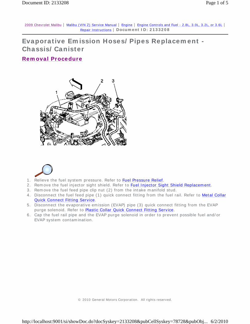
2009 Chevrolet Malibu | Malibu (VIN Z) Service Manual | Engine | Engine Controls and Fuel - 2.8L, 3.0L, 3.2L, or 3.6L | Repair Instructions | Document ID: 2133208
Evaporative Emission Hoses/Pipes Replacement - Chassis/Canister
Removal Procedure
1. Relieve the fuel system pressure. Refer to Fuel Pressure Relief. 2. Remove the fuel injector sight shield. Refer to Fuel Injector Sight Shield Replacement. 3. Remove the fuel feed pipe clip nut (2) from the intake manifold stud. 4. Disconnect the fuel feed pipe (1) quick connect fitting from the fuel rail. Refer to Metal Collar
Quick Connect Fitting Service. 5. Disconnect the evaporative emission (EVAP) pipe (3) quick connect fitting from the EVAP
purge solenoid. Refer to Plastic Collar Quick Connect Fitting Service. 6. Cap the fuel rail pipe and the EVAP purge solenoid in order to prevent possible fuel and/or
EVAP system contamination.
© 2010 General Motors Corporation. All rights reserved.
Page 1 of 5Document ID: 2133208
6/2/2010http://localhost:9001/si/showDoc.do?docSyskey=2133208&pubCellSyskey=78728&pubObj...
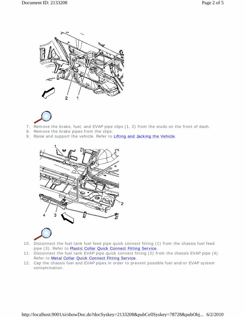
7. Remove the brake, fuel, and EVAP pipe clips (1, 2) from the studs on the front of dash. 8. Remove the brake pipes from the clips. 9. Raise and support the vehicle. Refer to Lifting and Jacking the Vehicle.
10. Disconnect the fuel tank fuel feed pipe quick connect fitting (1) from the chassis fuel feed
pipe (3). Refer to Plastic Collar Quick Connect Fitting Service. 11. Disconnect the fuel tank EVAP pipe quick connect fitting (2) from the chassis EVAP pipe (4).
Refer to Metal Collar Quick Connect Fitting Service. 12. Cap the chassis fuel and EVAP pipes in order to prevent possible fuel and/or EVAP system
contamination.
Page 2 of 5Document ID: 2133208
6/2/2010http://localhost:9001/si/showDoc.do?docSyskey=2133208&pubCellSyskey=78728&pubObj...

13. Remove the brake, fuel and EVAP pipe retainers (5) from the underbody studs. 14. Remove the brake pipes from the retainers. 15. Remove the fuel feed/EVAP pipe assembly from the vehicle. 16. Place the pipe assembly on a work bench. 17. Open and remove the upper fuel feed/EVAP pipe retainer (3). 18. Open and remove the front of dash fuel feed/EVAP pipe retainers (4). 19. Open and remove the underbody retainers (5). 20. Replace any retainers as necessary.
Installation Procedure
1. Install and close the underbody retainers (5).
Page 3 of 5Document ID: 2133208
6/2/2010http://localhost:9001/si/showDoc.do?docSyskey=2133208&pubCellSyskey=78728&pubObj...
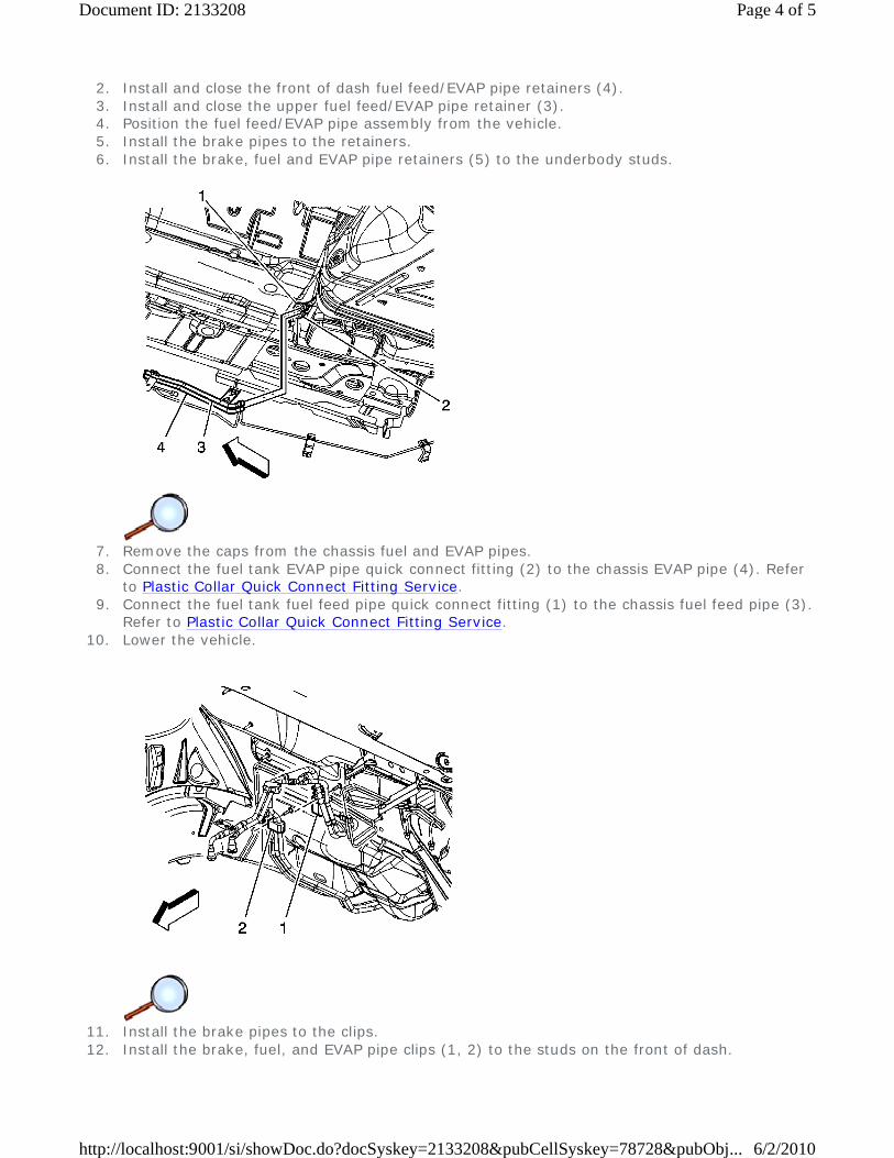
2. Install and close the front of dash fuel feed/EVAP pipe retainers (4). 3. Install and close the upper fuel feed/EVAP pipe retainer (3). 4. Position the fuel feed/EVAP pipe assembly from the vehicle. 5. Install the brake pipes to the retainers. 6. Install the brake, fuel and EVAP pipe retainers (5) to the underbody studs.
7. Remove the caps from the chassis fuel and EVAP pipes. 8. Connect the fuel tank EVAP pipe quick connect fitting (2) to the chassis EVAP pipe (4). Refer
to Plastic Collar Quick Connect Fitting Service. 9. Connect the fuel tank fuel feed pipe quick connect fitting (1) to the chassis fuel feed pipe (3).
Refer to Plastic Collar Quick Connect Fitting Service. 10. Lower the vehicle.
11. Install the brake pipes to the clips. 12. Install the brake, fuel, and EVAP pipe clips (1, 2) to the studs on the front of dash.
Page 4 of 5Document ID: 2133208
6/2/2010http://localhost:9001/si/showDoc.do?docSyskey=2133208&pubCellSyskey=78728&pubObj...
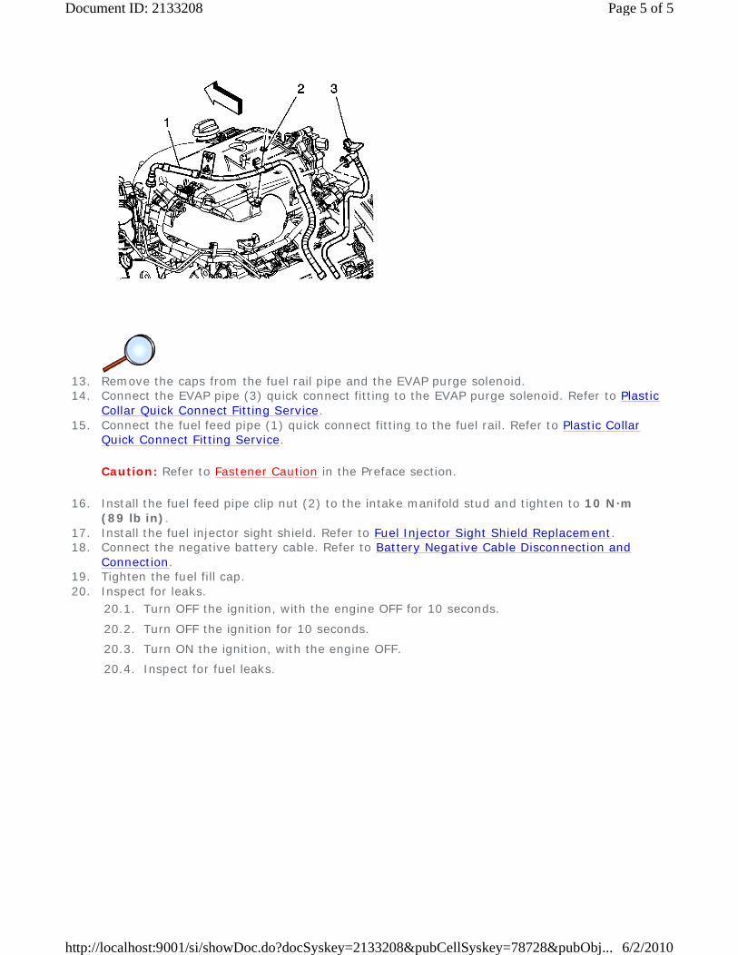
13. Remove the caps from the fuel rail pipe and the EVAP purge solenoid. 14. Connect the EVAP pipe (3) quick connect fitting to the EVAP purge solenoid. Refer to Plastic
Collar Quick Connect Fitting Service. 15. Connect the fuel feed pipe (1) quick connect fitting to the fuel rail. Refer to Plastic Collar
Quick Connect Fitting Service.
Caution: Refer to Fastener Caution in the Preface section.
16. Install the fuel feed pipe clip nut (2) to the intake manifold stud and tighten to 10 N·m (89 lb in).
17. Install the fuel injector sight shield. Refer to Fuel Injector Sight Shield Replacement. 18. Connect the negative battery cable. Refer to Battery Negative Cable Disconnection and
Connection. 19. Tighten the fuel fill cap. 20. Inspect for leaks.
20.1. Turn OFF the ignition, with the engine OFF for 10 seconds.
20.2. Turn OFF the ignition for 10 seconds.
20.3. Turn ON the ignition, with the engine OFF.
20.4. Inspect for fuel leaks.
Page 5 of 5Document ID: 2133208
6/2/2010http://localhost:9001/si/showDoc.do?docSyskey=2133208&pubCellSyskey=78728&pubObj...
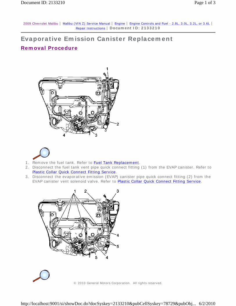
2009 Chevrolet Malibu | Malibu (VIN Z) Service Manual | Engine | Engine Controls and Fuel - 2.8L, 3.0L, 3.2L, or 3.6L | Repair Instructions | Document ID: 2133210
Evaporative Emission Canister Replacement
Removal Procedure
1. Remove the fuel tank. Refer to Fuel Tank Replacement. 2. Disconnect the fuel tank vent pipe quick connect fitting (1) from the EVAP canister. Refer to
Plastic Collar Quick Connect Fitting Service. 3. Disconnect the evaporative emission (EVAP) canister pipe quick connect fitting (2) from the
EVAP canister vent solenoid valve. Refer to Plastic Collar Quick Connect Fitting Service.
© 2010 General Motors Corporation. All rights reserved.
Page 1 of 3Document ID: 2133210
6/2/2010http://localhost:9001/si/showDoc.do?docSyskey=2133210&pubCellSyskey=78729&pubObj...
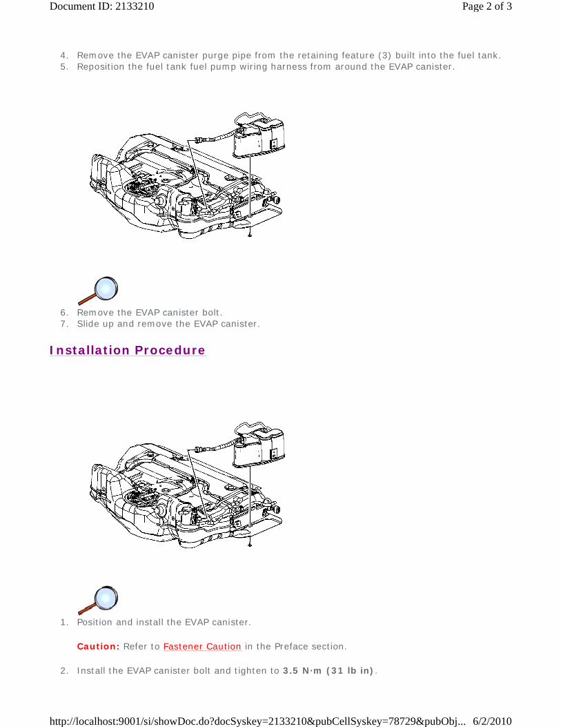
4. Remove the EVAP canister purge pipe from the retaining feature (3) built into the fuel tank. 5. Reposition the fuel tank fuel pump wiring harness from around the EVAP canister.
6. Remove the EVAP canister bolt. 7. Slide up and remove the EVAP canister.
Installation Procedure
1. Position and install the EVAP canister.
Caution: Refer to Fastener Caution in the Preface section.
2. Install the EVAP canister bolt and tighten to 3.5 N·m (31 lb in).
Page 2 of 3Document ID: 2133210
6/2/2010http://localhost:9001/si/showDoc.do?docSyskey=2133210&pubCellSyskey=78729&pubObj...

3. Position the fuel tank fuel pump wiring harness around the EVAP canister. 4. Install the EVAP canister purge pipe to the retaining feature (3) built into the fuel tank.
5. Connect the EVAP canister pipe quick connect fitting (2) to the EVAP canister vent solenoid
valve. Refer to Plastic Collar Quick Connect Fitting Service. 6. Connect the EVAP canister vent pipe quick connect fitting (1) to the EVAP canister. Refer to
Plastic Collar Quick Connect Fitting Service. 7. Install the fuel tank. Refer to Fuel Tank Replacement.
Page 3 of 3Document ID: 2133210
6/2/2010http://localhost:9001/si/showDoc.do?docSyskey=2133210&pubCellSyskey=78729&pubObj...

2009 Chevrolet Malibu | Malibu (VIN Z) Service Manual | Engine | Engine Controls and Fuel - 2.8L, 3.0L, 3.2L, or 3.6L | Repair Instructions | Document ID: 2133213
Evaporative Emission System Cleaning
Special Tools
J 41413 EVAP Pressure and Purge Station
Inspection Procedure
Caution: Use the EVAP Pressure/Purge Diagnostic Station J 41413 in order to provide a clean, dry, low pressure gas source. Do not substitute any other pressurized gas source. Damage may result to the EVAP system.
Note: Proceed with the following procedure only if referenced by an evaporative emission (EVAP) diagnostic or repair procedure.
1. Turn OFF the ignition. 2. Remove the EVAP canister purge valve. Refer to Evaporative Emission Canister Purge
Solenoid Valve Replacement. 3. Lightly tap the EVAP canister purge valve on a hard surface. 4. Inspect for carbon particles exiting either of the vacuum ports.
Cleaning Procedure
1. Raise and support the vehicle. Refer to Lifting and Jacking the Vehicle. 2. Remove the EVAP canister. Refer to Evaporative Emission Canister Replacement. 3. Turn OFF the main valve on the J 41413 . 4. Disconnect the hose from the diagnostic station pressure regulator. 5. Using a section of vacuum hose, connect one end onto the EVAP pressure/purge diagnostic
station pressure regulator. 6. Connect the other end of the vacuum hose to the canister side of the purge pipe. 7. Turn ON the main nitrogen cylinder valve and continue to discharge nitrogen for 15 seconds. 8. If the nitrogen does not clear the blockage, replace the purge pipe. 9. Return the EVAP pressure/purge diagnostic station to the stations original condition.
10. Install a new EVAP canister. Refer to Evaporative Emission Canister Replacement. 11. Lower the vehicle. 12. Install a new EVAP canister purge valve. Refer to Evaporative Emission Canister Purge
Solenoid Valve Replacement. 13. Return to the diagnostic table that sent you here.
• If no carbon particles were detected, but a blockage was detected during a diagnostic procedure, install the original EVAP canister purge valve. Continue with the cleaning procedure.
• If carbon particles are found during the inspection procedure, continue with the cleaning procedure.
• If a diagnostic procedure directed you to replace the EVAP canister purge valve and no carbon particles were detected, replace the EVAP canister purge valve. Return to the published service procedure.
© 2010 General Motors Corporation. All rights reserved.
Page 1 of 1Document ID: 2133213
6/2/2010http://localhost:9001/si/showDoc.do?docSyskey=2133213&pubCellSyskey=78731&pubObj...
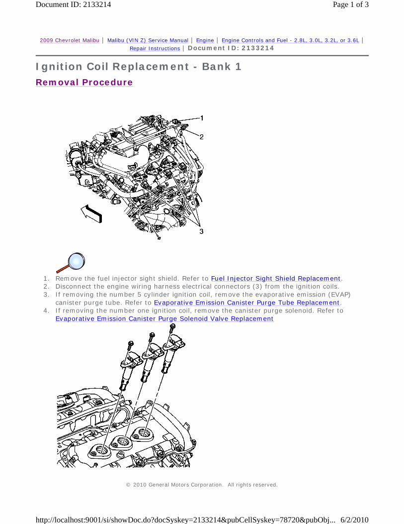
2009 Chevrolet Malibu | Malibu (VIN Z) Service Manual | Engine | Engine Controls and Fuel - 2.8L, 3.0L, 3.2L, or 3.6L | Repair Instructions | Document ID: 2133214
Ignition Coil Replacement - Bank 1
Removal Procedure
1. Remove the fuel injector sight shield. Refer to Fuel Injector Sight Shield Replacement. 2. Disconnect the engine wiring harness electrical connectors (3) from the ignition coils. 3. If removing the number 5 cylinder ignition coil, remove the evaporative emission (EVAP)
canister purge tube. Refer to Evaporative Emission Canister Purge Tube Replacement. 4. If removing the number one ignition coil, remove the canister purge solenoid. Refer to
Evaporative Emission Canister Purge Solenoid Valve Replacement
© 2010 General Motors Corporation. All rights reserved.
Page 1 of 3Document ID: 2133214
6/2/2010http://localhost:9001/si/showDoc.do?docSyskey=2133214&pubCellSyskey=78720&pubObj...
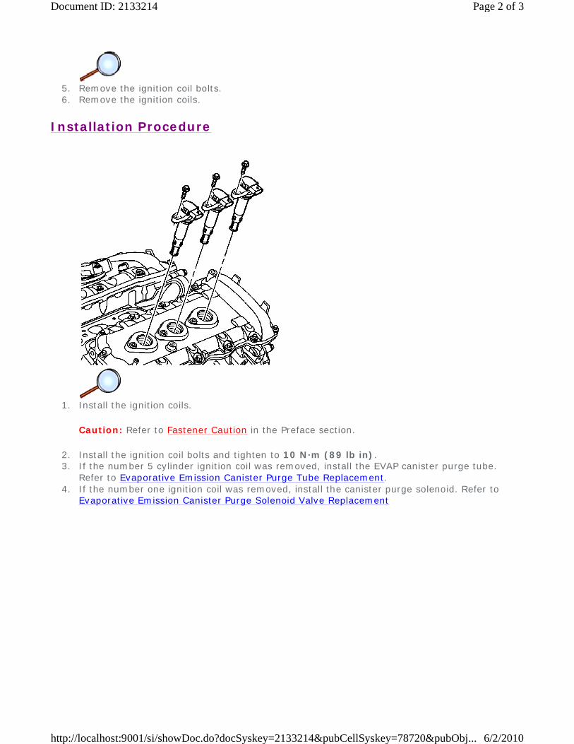
5. Remove the ignition coil bolts. 6. Remove the ignition coils.
Installation Procedure
1. Install the ignition coils.
Caution: Refer to Fastener Caution in the Preface section.
2. Install the ignition coil bolts and tighten to 10 N·m (89 lb in). 3. If the number 5 cylinder ignition coil was removed, install the EVAP canister purge tube.
Refer to Evaporative Emission Canister Purge Tube Replacement. 4. If the number one ignition coil was removed, install the canister purge solenoid. Refer to
Evaporative Emission Canister Purge Solenoid Valve Replacement
Page 2 of 3Document ID: 2133214
6/2/2010http://localhost:9001/si/showDoc.do?docSyskey=2133214&pubCellSyskey=78720&pubObj...
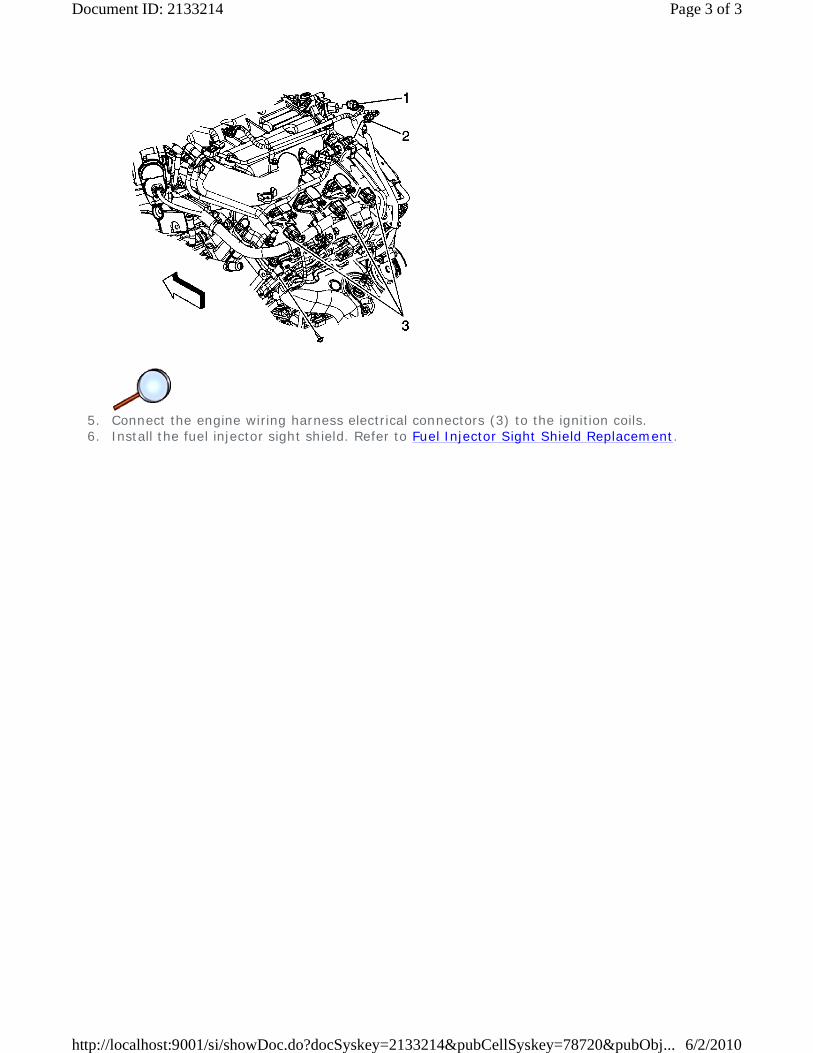
5. Connect the engine wiring harness electrical connectors (3) to the ignition coils. 6. Install the fuel injector sight shield. Refer to Fuel Injector Sight Shield Replacement.
Page 3 of 3Document ID: 2133214
6/2/2010http://localhost:9001/si/showDoc.do?docSyskey=2133214&pubCellSyskey=78720&pubObj...
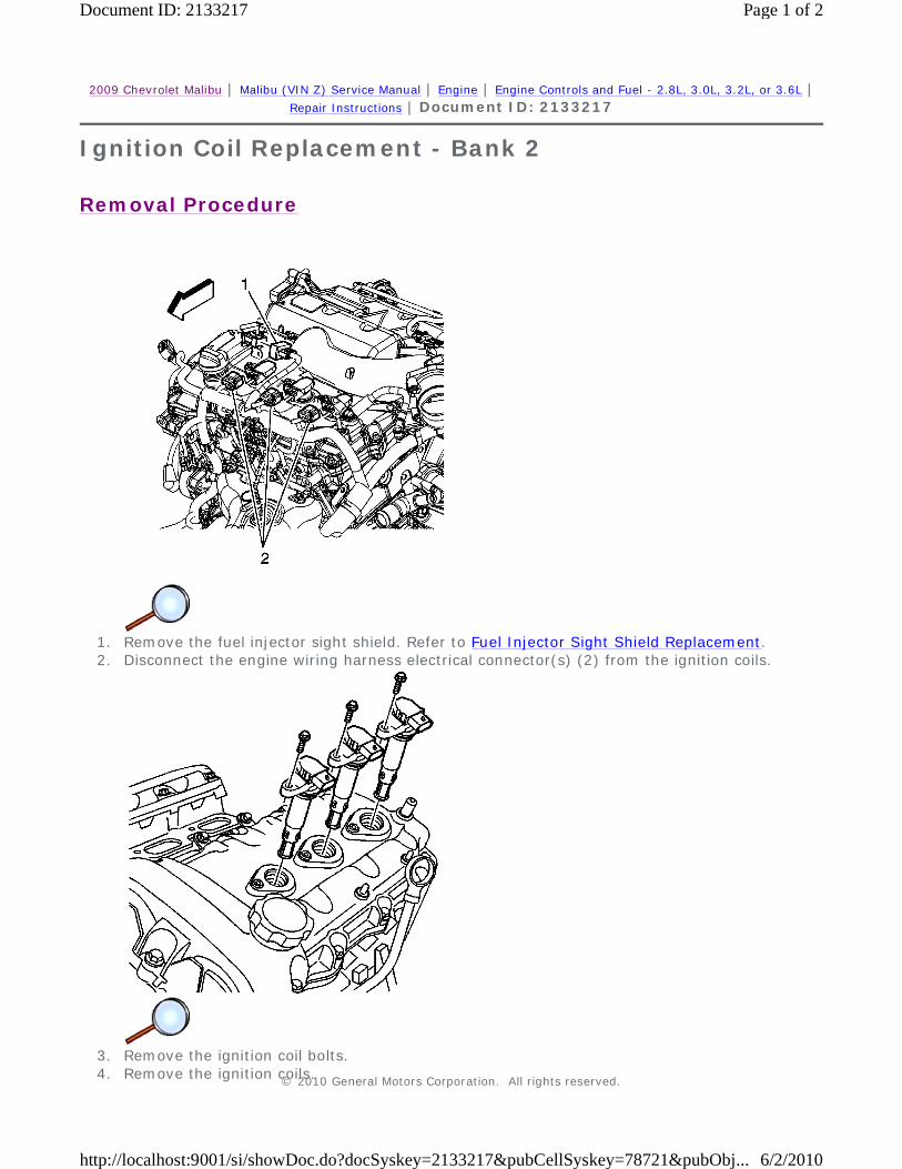
2009 Chevrolet Malibu | Malibu (VIN Z) Service Manual | Engine | Engine Controls and Fuel - 2.8L, 3.0L, 3.2L, or 3.6L | Repair Instructions | Document ID: 2133217
Ignition Coil Replacement - Bank 2
Removal Procedure
1. Remove the fuel injector sight shield. Refer to Fuel Injector Sight Shield Replacement. 2. Disconnect the engine wiring harness electrical connector(s) (2) from the ignition coils.
3. Remove the ignition coil bolts. 4. Remove the ignition coils.
© 2010 General Motors Corporation. All rights reserved.
Page 1 of 2Document ID: 2133217
6/2/2010http://localhost:9001/si/showDoc.do?docSyskey=2133217&pubCellSyskey=78721&pubObj...
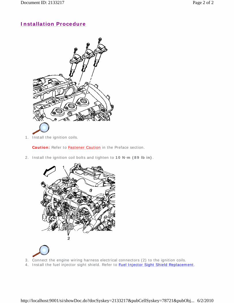
Installation Procedure
1. Install the ignition coils.
Caution: Refer to Fastener Caution in the Preface section.
2. Install the ignition coil bolts and tighten to 10 N·m (89 lb in).
3. Connect the engine wiring harness electrical connectors (2) to the ignition coils. 4. Install the fuel injector sight shield. Refer to Fuel Injector Sight Shield Replacement.
Page 2 of 2Document ID: 2133217
6/2/2010http://localhost:9001/si/showDoc.do?docSyskey=2133217&pubCellSyskey=78721&pubObj...
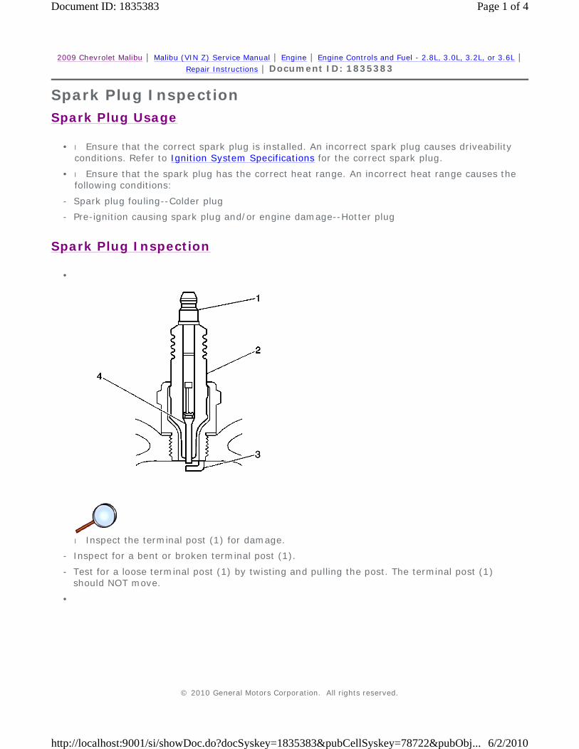
2009 Chevrolet Malibu | Malibu (VIN Z) Service Manual | Engine | Engine Controls and Fuel - 2.8L, 3.0L, 3.2L, or 3.6L | Repair Instructions | Document ID: 1835383
Spark Plug Inspection
Spark Plug Usage
Spark Plug Inspection
• l Ensure that the correct spark plug is installed. An incorrect spark plug causes driveability conditions. Refer to Ignition System Specifications for the correct spark plug.
• l Ensure that the spark plug has the correct heat range. An incorrect heat range causes the following conditions:
- Spark plug fouling--Colder plug
- Pre-ignition causing spark plug and/or engine damage--Hotter plug
•
l Inspect the terminal post (1) for damage.
- Inspect for a bent or broken terminal post (1).
-
Test for a loose terminal post (1) by twisting and pulling the post. The terminal post (1) should NOT move.
•
© 2010 General Motors Corporation. All rights reserved.
Page 1 of 4Document ID: 1835383
6/2/2010http://localhost:9001/si/showDoc.do?docSyskey=1835383&pubCellSyskey=78722&pubObj...
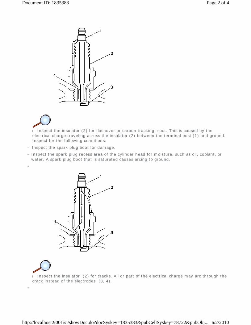
l Inspect the insulator (2) for flashover or carbon tracking, soot. This is caused by the electrical charge traveling across the insulator (2) between the terminal post (1) and ground. Inspect for the following conditions:
- Inspect the spark plug boot for damage.
-
Inspect the spark plug recess area of the cylinder head for moisture, such as oil, coolant, or water. A spark plug boot that is saturated causes arcing to ground.
•
l Inspect the insulator (2) for cracks. All or part of the electrical charge may arc through the crack instead of the electrodes (3, 4).
•
Page 2 of 4Document ID: 1835383
6/2/2010http://localhost:9001/si/showDoc.do?docSyskey=1835383&pubCellSyskey=78722&pubObj...

Spark Plug Visual Inspection
l Inspect for evidence of improper arcing.
-
Measure the gap between the center electrode (4) and the side electrode (3) terminals. Refer to Ignition System Specifications . An excessively wide electrode gap can prevent correct spark plug operation.
-
Inspect for the correct spark plug torque. Refer to Ignition System Specifications . Insufficient torque can prevent correct spark plug operation. An over torqued spark plug, causes the insulator (2) to crack.
-
Inspect for signs of tracking that occurred near the insulator tip instead of the center electrode (4).
- Inspect for a broken or worn side electrode (3).
- Inspect for a broken, worn, or loose center electrode (4) by shaking the spark plug.
• A rattling sound indicates internal damage.
• A loose center electrode (4) reduces the spark intensity.
-
Inspect for bridged electrodes (3, 4). Deposits on the electrodes (3, 4) reduce or eliminates the gap.
- Inspect for worn or missing platinum pads on the electrodes (3, 4), if equipped.
- Inspect for excessive fouling.
• l Inspect the spark plug recess area of the cylinder head for debris. Dirty or damaged threads can cause the spark plug not to seat correctly during installation.
• l Normal operation--Brown to grayish-tan with small amounts of white powdery deposits are normal combustion by-products from fuels with additives.
• l Carbon fouled--Dry, fluffy, black carbon or soot caused by the following conditions:
- Rich fuel mixtures
• Leaking fuel injectors
Page 3 of 4Document ID: 1835383
6/2/2010http://localhost:9001/si/showDoc.do?docSyskey=1835383&pubCellSyskey=78722&pubObj...
• Excessive fuel pressure
• Restricted air filter element
• Incorrect combustion
- Reduced ignition system voltage output
• Weak coils
• Worn ignition wires
• Incorrect spark plug gap
-
Excessive idling or slow speeds under light loads can keep spark plug temperatures so low that normal combustion deposits may not burn off.
• l Deposit fouling--Oil, coolant, or additives that include substances such as silicone, very white coating, reduces the spark intensity. Most powdery deposits will not effect spark intensity unless they form into a glazing over the electrode.
Page 4 of 4Document ID: 1835383
6/2/2010http://localhost:9001/si/showDoc.do?docSyskey=1835383&pubCellSyskey=78722&pubObj...
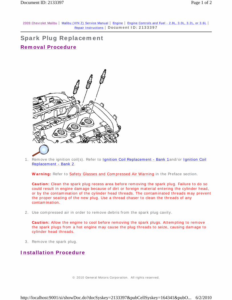
2009 Chevrolet Malibu | Malibu (VIN Z) Service Manual | Engine | Engine Controls and Fuel - 2.8L, 3.0L, 3.2L, or 3.6L | Repair Instructions | Document ID: 2133397
Spark Plug Replacement
Removal Procedure
1. Remove the ignition coil(s). Refer to Ignition Coil Replacement - Bank 1and/or Ignition Coil
Replacement - Bank 2.
Warning: Refer to Safety Glasses and Compressed Air Warning in the Preface section.
Caution: Clean the spark plug recess area before removing the spark plug. Failure to do so could result in engine damage because of dirt or foreign material entering the cylinder head, or by the contamination of the cylinder head threads. The contaminated threads may prevent the proper seating of the new plug. Use a thread chaser to clean the threads of any contamination.
2. Use compressed air in order to remove debris from the spark plug cavity.
Caution: Allow the engine to cool before removing the spark plugs. Attempting to remove the spark plugs from a hot engine may cause the plug threads to seize, causing damage to cylinder head threads.
3. Remove the spark plug.
Installation Procedure
© 2010 General Motors Corporation. All rights reserved.
Page 1 of 2Document ID: 2133397
6/2/2010http://localhost:9001/si/showDoc.do?docSyskey=2133397&pubCellSyskey=164341&pubO...
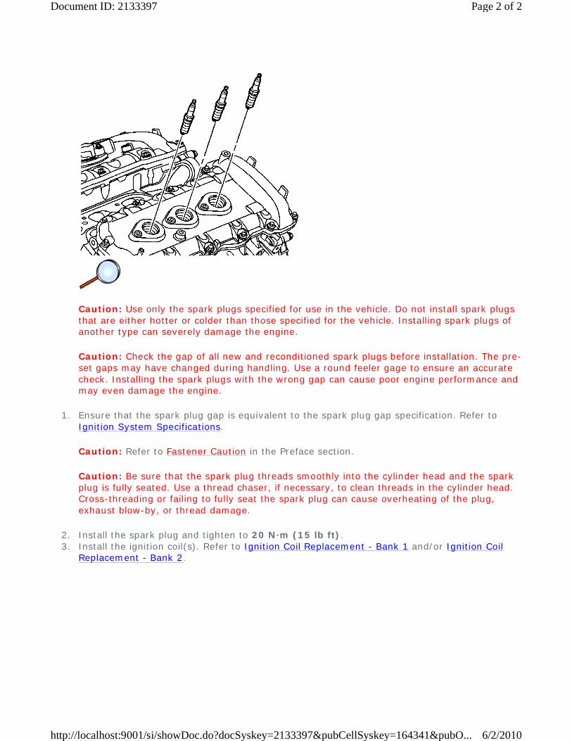
Caution: Use only the spark plugs specified for use in the vehicle. Do not install spark plugs that are either hotter or colder than those specified for the vehicle. Installing spark plugs of another type can severely damage the engine.
Caution: Check the gap of all new and reconditioned spark plugs before installation. The pre-set gaps may have changed during handling. Use a round feeler gage to ensure an accurate check. Installing the spark plugs with the wrong gap can cause poor engine performance and may even damage the engine.
1. Ensure that the spark plug gap is equivalent to the spark plug gap specification. Refer to Ignition System Specifications.
Caution: Refer to Fastener Caution in the Preface section.
Caution: Be sure that the spark plug threads smoothly into the cylinder head and the spark plug is fully seated. Use a thread chaser, if necessary, to clean threads in the cylinder head. Cross-threading or failing to fully seat the spark plug can cause overheating of the plug, exhaust blow-by, or thread damage.
2. Install the spark plug and tighten to 20 N·m (15 lb ft). 3. Install the ignition coil(s). Refer to Ignition Coil Replacement - Bank 1 and/or Ignition Coil
Replacement - Bank 2.
Page 2 of 2Document ID: 2133397
6/2/2010http://localhost:9001/si/showDoc.do?docSyskey=2133397&pubCellSyskey=164341&pubO...
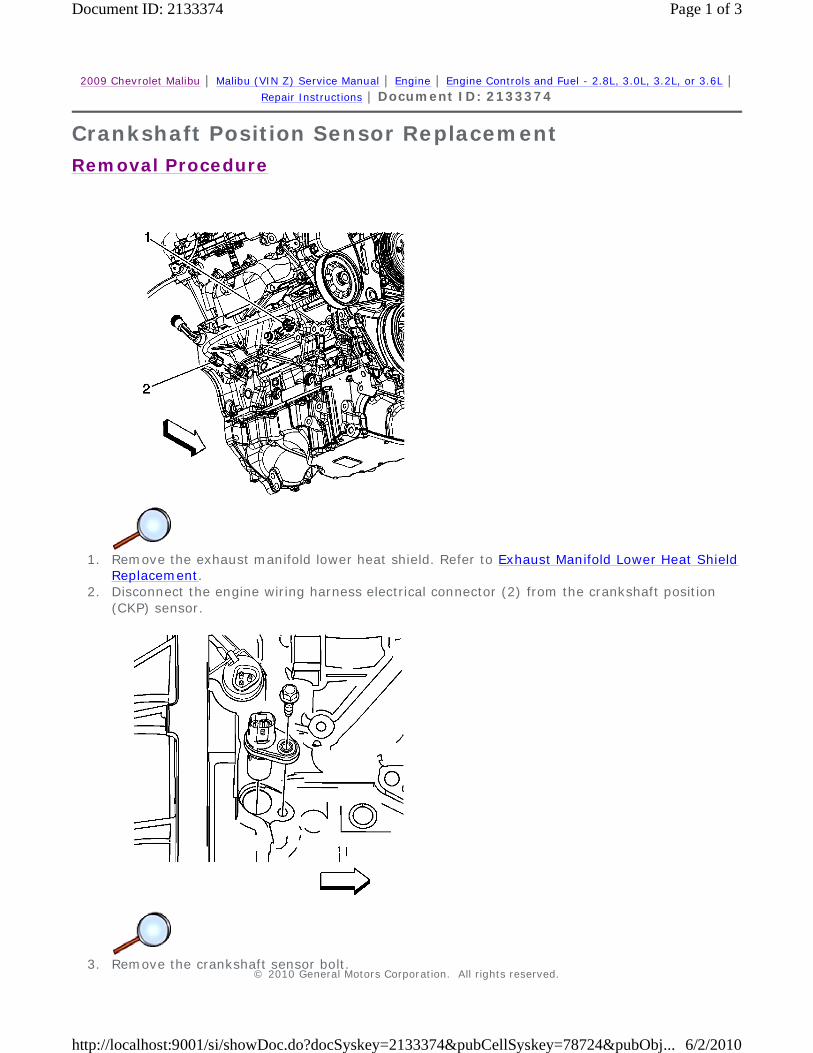
2009 Chevrolet Malibu | Malibu (VIN Z) Service Manual | Engine | Engine Controls and Fuel - 2.8L, 3.0L, 3.2L, or 3.6L | Repair Instructions | Document ID: 2133374
Crankshaft Position Sensor Replacement
Removal Procedure
1. Remove the exhaust manifold lower heat shield. Refer to Exhaust Manifold Lower Heat Shield
Replacement. 2. Disconnect the engine wiring harness electrical connector (2) from the crankshaft position
(CKP) sensor.
3. Remove the crankshaft sensor bolt.
© 2010 General Motors Corporation. All rights reserved.
Page 1 of 3Document ID: 2133374
6/2/2010http://localhost:9001/si/showDoc.do?docSyskey=2133374&pubCellSyskey=78724&pubObj...

4. Remove the crankshaft sensor.
Installation Procedure
1. Install the crankshaft position sensor.
Caution: Refer to Fastener Caution in the Preface section.
2. Install the crankshaft position sensor bolt and tighten to 10 N·m (89 lb in).
3. Connect the engine wiring harness electrical connector (2) to the CKP sensor. 4. Install the exhaust manifold lower heat shield. Refer to Exhaust Manifold Lower Heat Shield
Replacement.
Page 2 of 3Document ID: 2133374
6/2/2010http://localhost:9001/si/showDoc.do?docSyskey=2133374&pubCellSyskey=78724&pubObj...
5. Perform the Crankshaft Position System Variation Learn procedure. Refer to Crankshaft Position System Variation Learn.
Page 3 of 3Document ID: 2133374
6/2/2010http://localhost:9001/si/showDoc.do?docSyskey=2133374&pubCellSyskey=78724&pubObj...
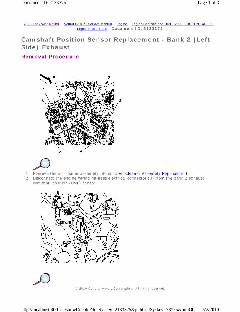
2009 Chevrolet Malibu | Malibu (VIN Z) Service Manual | Engine | Engine Controls and Fuel - 2.8L, 3.0L, 3.2L, or 3.6L | Repair Instructions | Document ID: 2133375
Camshaft Position Sensor Replacement - Bank 2 (Left Side) Exhaust
Removal Procedure
1. Remove the air cleaner assembly. Refer to Air Cleaner Assembly Replacement. 2. Disconnect the engine wiring harness electrical connector (3) from the bank 2 exhaust
camshaft position (CMP) sensor.
© 2010 General Motors Corporation. All rights reserved.
Page 1 of 3Document ID: 2133375
6/2/2010http://localhost:9001/si/showDoc.do?docSyskey=2133375&pubCellSyskey=78725&pubObj...
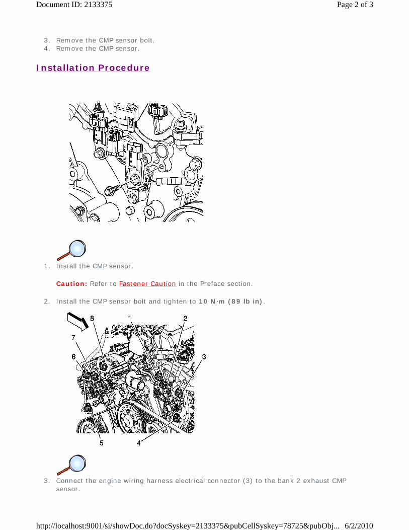
3. Remove the CMP sensor bolt. 4. Remove the CMP sensor.
Installation Procedure
1. Install the CMP sensor.
Caution: Refer to Fastener Caution in the Preface section.
2. Install the CMP sensor bolt and tighten to 10 N·m (89 lb in).
3. Connect the engine wiring harness electrical connector (3) to the bank 2 exhaust CMP
sensor.
Page 2 of 3Document ID: 2133375
6/2/2010http://localhost:9001/si/showDoc.do?docSyskey=2133375&pubCellSyskey=78725&pubObj...
4. Install the air cleaner assembly. Refer to Air Cleaner Assembly Replacement.
Page 3 of 3Document ID: 2133375
6/2/2010http://localhost:9001/si/showDoc.do?docSyskey=2133375&pubCellSyskey=78725&pubObj...
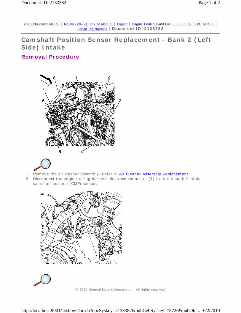
2009 Chevrolet Malibu | Malibu (VIN Z) Service Manual | Engine | Engine Controls and Fuel - 2.8L, 3.0L, 3.2L, or 3.6L | Repair Instructions | Document ID: 2133382
Camshaft Position Sensor Replacement - Bank 2 (Left Side) Intake
Removal Procedure
1. Remove the air cleaner assembly. Refer to Air Cleaner Assembly Replacement. 2. Disconnect the engine wiring harness electrical connector (1) from the bank 2 intake
camshaft position (CMP) sensor.
© 2010 General Motors Corporation. All rights reserved.
Page 1 of 2Document ID: 2133382
6/2/2010http://localhost:9001/si/showDoc.do?docSyskey=2133382&pubCellSyskey=78726&pubObj...

3. Remove the CMP sensor bolt. 4. Remove the CMP sensor.
Installation Procedure
1. Install the CMP sensor.
Caution: Refer to Fastener Caution in the Preface section.
2. Install the CMP sensor bolt and tighten to 10 N·m (89 lb in).
3. Connect the engine wiring harness electrical connector (1) to the bank 2 intake CMP sensor. 4. Install the air cleaner assembly. Refer to Air Cleaner Assembly Replacement.
Page 2 of 2Document ID: 2133382
6/2/2010http://localhost:9001/si/showDoc.do?docSyskey=2133382&pubCellSyskey=78726&pubObj...

2009 Chevrolet Malibu | Malibu (VIN Z) Service Manual | Engine | Engine Controls and Fuel - 2.8L, 3.0L, 3.2L, or 3.6L | Repair Instructions | Document ID: 2133387
Camshaft Position Sensor Replacement - Bank 1 (Right Side) Exhaust
Removal Procedure
1. Remove the air cleaner assembly. Refer to Air Cleaner Assembly Replacement. 2. Disconnect the engine wiring harness electrical connector (6) from the bank 1 exhaust
camshaft position (CMP) sensor.
© 2010 General Motors Corporation. All rights reserved.
Page 1 of 3Document ID: 2133387
6/2/2010http://localhost:9001/si/showDoc.do?docSyskey=2133387&pubCellSyskey=78715&pubObj...
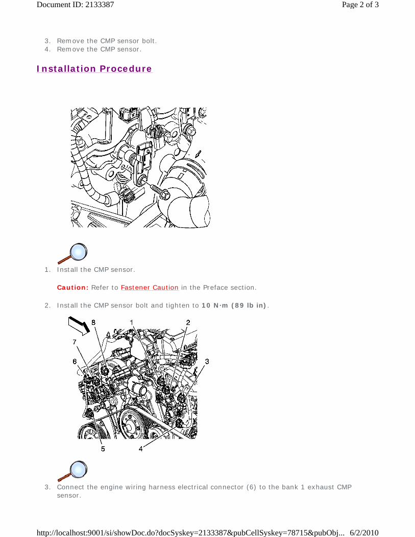
3. Remove the CMP sensor bolt. 4. Remove the CMP sensor.
Installation Procedure
1. Install the CMP sensor.
Caution: Refer to Fastener Caution in the Preface section.
2. Install the CMP sensor bolt and tighten to 10 N·m (89 lb in).
3. Connect the engine wiring harness electrical connector (6) to the bank 1 exhaust CMP
sensor.
Page 2 of 3Document ID: 2133387
6/2/2010http://localhost:9001/si/showDoc.do?docSyskey=2133387&pubCellSyskey=78715&pubObj...

4. Install the air cleaner assembly. Refer to Air Cleaner Assembly Replacement.
Page 3 of 3Document ID: 2133387
6/2/2010http://localhost:9001/si/showDoc.do?docSyskey=2133387&pubCellSyskey=78715&pubObj...
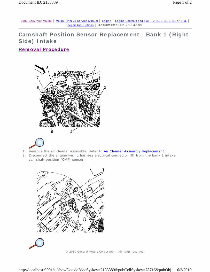
2009 Chevrolet Malibu | Malibu (VIN Z) Service Manual | Engine | Engine Controls and Fuel - 2.8L, 3.0L, 3.2L, or 3.6L | Repair Instructions | Document ID: 2133389
Camshaft Position Sensor Replacement - Bank 1 (Right Side) Intake
Removal Procedure
1. Remove the air cleaner assembly. Refer to Air Cleaner Assembly Replacement. 2. Disconnect the engine wiring harness electrical connector (8) from the bank 1 intake
camshaft position (CMP) sensor.
© 2010 General Motors Corporation. All rights reserved.
Page 1 of 2Document ID: 2133389
6/2/2010http://localhost:9001/si/showDoc.do?docSyskey=2133389&pubCellSyskey=78716&pubObj...

3. Remove the CMP sensor bolt. 4. Remove the CMP sensor.
Installation Procedure
1. Install the CMP sensor.
Caution: Refer to Fastener Caution in the Preface section.
2. Install the CMP sensor bolt and tighten to 10 N·m (89 lb in).
3. Connect the engine wiring harness electrical connector (8) to the bank 1 intake CMP sensor. 4. Install the air cleaner assembly. Refer to Air Cleaner Assembly Replacement.
Page 2 of 2Document ID: 2133389
6/2/2010http://localhost:9001/si/showDoc.do?docSyskey=2133389&pubCellSyskey=78716&pubObj...
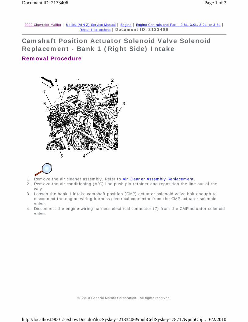
2009 Chevrolet Malibu | Malibu (VIN Z) Service Manual | Engine | Engine Controls and Fuel - 2.8L, 3.0L, 3.2L, or 3.6L | Repair Instructions | Document ID: 2133406
Camshaft Position Actuator Solenoid Valve Solenoid Replacement - Bank 1 (Right Side) Intake
Removal Procedure
1. Remove the air cleaner assembly. Refer to Air Cleaner Assembly Replacement. 2. Remove the air conditioning (A/C) line push pin retainer and reposition the line out of the
way. 3. Loosen the bank 1 intake camshaft position (CMP) actuator solenoid valve bolt enough to
disconnect the engine wiring harness electrical connector from the CMP actuator solenoid valve.
4. Disconnect the engine wiring harness electrical connector (7) from the CMP actuator solenoid valve.
© 2010 General Motors Corporation. All rights reserved.
Page 1 of 3Document ID: 2133406
6/2/2010http://localhost:9001/si/showDoc.do?docSyskey=2133406&pubCellSyskey=78717&pubObj...
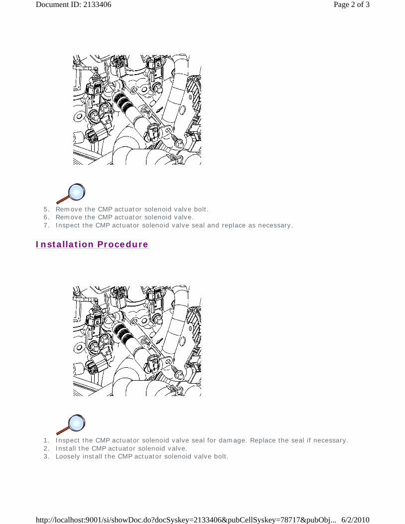
5. Remove the CMP actuator solenoid valve bolt. 6. Remove the CMP actuator solenoid valve. 7. Inspect the CMP actuator solenoid valve seal and replace as necessary.
Installation Procedure
1. Inspect the CMP actuator solenoid valve seal for damage. Replace the seal if necessary. 2. Install the CMP actuator solenoid valve. 3. Loosely install the CMP actuator solenoid valve bolt.
Page 2 of 3Document ID: 2133406
6/2/2010http://localhost:9001/si/showDoc.do?docSyskey=2133406&pubCellSyskey=78717&pubObj...
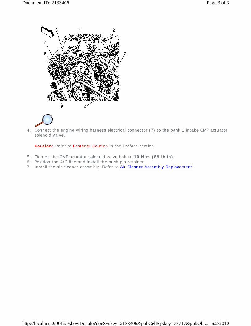
4. Connect the engine wiring harness electrical connector (7) to the bank 1 intake CMP actuator
solenoid valve.
Caution: Refer to Fastener Caution in the Preface section.
5. Tighten the CMP actuator solenoid valve bolt to 10 N·m (89 lb in). 6. Position the A/C line and install the push pin retainer. 7. Install the air cleaner assembly. Refer to Air Cleaner Assembly Replacement.
Page 3 of 3Document ID: 2133406
6/2/2010http://localhost:9001/si/showDoc.do?docSyskey=2133406&pubCellSyskey=78717&pubObj...

2009 Chevrolet Malibu | Malibu (VIN Z) Service Manual | Engine | Engine Controls and Fuel - 2.8L, 3.0L, 3.2L, or 3.6L | Repair Instructions | Document ID: 2133410
Camshaft Position Actuator Solenoid Valve Solenoid Replacement - Bank 1 (Right Side) Exhaust
Removal Procedure
1. Remove the air cleaner assembly. Refer to Air Cleaner Assembly Replacement. 2. Disconnect the engine wiring harness electrical connector (5) from the bank 1 exhaust
camshaft position (CMP) actuator solenoid valve.
© 2010 General Motors Corporation. All rights reserved.
Page 1 of 3Document ID: 2133410
6/2/2010http://localhost:9001/si/showDoc.do?docSyskey=2133410&pubCellSyskey=78718&pubObj...
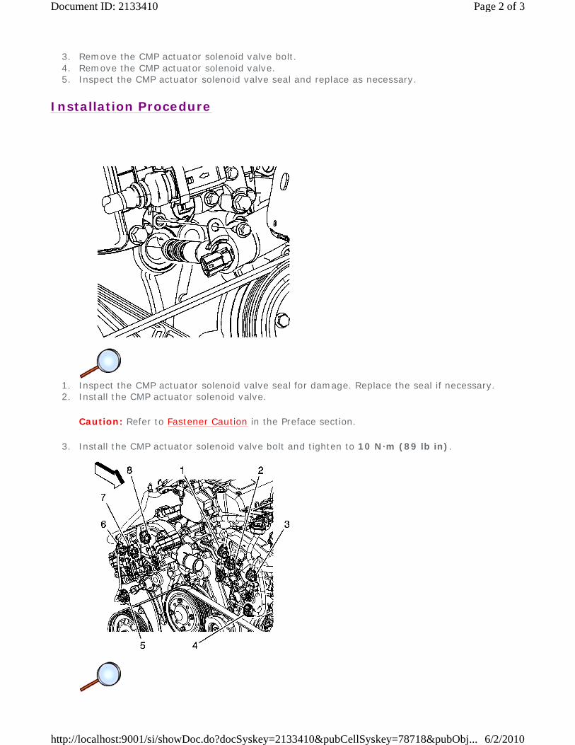
3. Remove the CMP actuator solenoid valve bolt. 4. Remove the CMP actuator solenoid valve. 5. Inspect the CMP actuator solenoid valve seal and replace as necessary.
Installation Procedure
1. Inspect the CMP actuator solenoid valve seal for damage. Replace the seal if necessary. 2. Install the CMP actuator solenoid valve.
Caution: Refer to Fastener Caution in the Preface section.
3. Install the CMP actuator solenoid valve bolt and tighten to 10 N·m (89 lb in).
Page 2 of 3Document ID: 2133410
6/2/2010http://localhost:9001/si/showDoc.do?docSyskey=2133410&pubCellSyskey=78718&pubObj...
4. Connect the engine wiring harness electrical connector (5) to the bank 1 exhaust CMP actuator solenoid valve.
5. Install the air cleaner assembly. Refer to Air Cleaner Assembly Replacement.
Page 3 of 3Document ID: 2133410
6/2/2010http://localhost:9001/si/showDoc.do?docSyskey=2133410&pubCellSyskey=78718&pubObj...
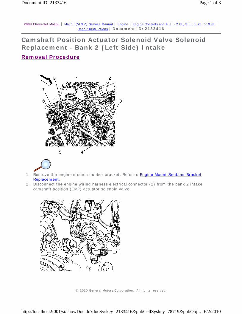
2009 Chevrolet Malibu | Malibu (VIN Z) Service Manual | Engine | Engine Controls and Fuel - 2.8L, 3.0L, 3.2L, or 3.6L | Repair Instructions | Document ID: 2133416
Camshaft Position Actuator Solenoid Valve Solenoid Replacement - Bank 2 (Left Side) Intake
Removal Procedure
1. Remove the engine mount snubber bracket. Refer to Engine Mount Snubber Bracket
Replacement. 2. Disconnect the engine wiring harness electrical connector (2) from the bank 2 intake
camshaft position (CMP) actuator solenoid valve.
© 2010 General Motors Corporation. All rights reserved.
Page 1 of 3Document ID: 2133416
6/2/2010http://localhost:9001/si/showDoc.do?docSyskey=2133416&pubCellSyskey=78719&pubObj...
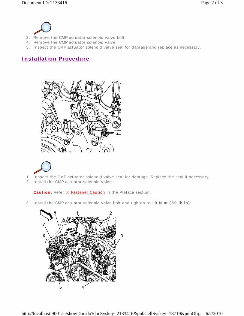
3. Remove the CMP actuator solenoid valve bolt. 4. Remove the CMP actuator solenoid valve. 5. Inspect the CMP actuator solenoid valve seal for damage and replace as necessary.
Installation Procedure
1. Inspect the CMP actuator solenoid valve seal for damage. Replace the seal if necessary. 2. Install the CMP actuator solenoid valve.
Caution: Refer to Fastener Caution in the Preface section.
3. Install the CMP actuator solenoid valve bolt and tighten to 10 N·m (89 lb in).
Page 2 of 3Document ID: 2133416
6/2/2010http://localhost:9001/si/showDoc.do?docSyskey=2133416&pubCellSyskey=78719&pubObj...
4. Connect the engine wiring harness electrical connector (2) to the bank 2 intake CMP actuator
solenoid valve. 5. Install the engine mount snubber bracket. Refer to Engine Mount Snubber Bracket
Replacement.
Page 3 of 3Document ID: 2133416
6/2/2010http://localhost:9001/si/showDoc.do?docSyskey=2133416&pubCellSyskey=78719&pubObj...
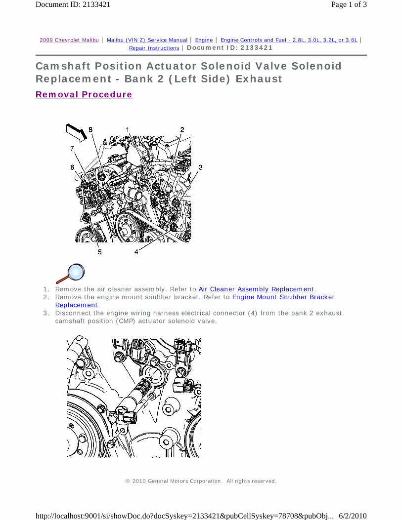
2009 Chevrolet Malibu | Malibu (VIN Z) Service Manual | Engine | Engine Controls and Fuel - 2.8L, 3.0L, 3.2L, or 3.6L | Repair Instructions | Document ID: 2133421
Camshaft Position Actuator Solenoid Valve Solenoid Replacement - Bank 2 (Left Side) Exhaust
Removal Procedure
1. Remove the air cleaner assembly. Refer to Air Cleaner Assembly Replacement. 2. Remove the engine mount snubber bracket. Refer to Engine Mount Snubber Bracket
Replacement. 3. Disconnect the engine wiring harness electrical connector (4) from the bank 2 exhaust
camshaft position (CMP) actuator solenoid valve.
© 2010 General Motors Corporation. All rights reserved.
Page 1 of 3Document ID: 2133421
6/2/2010http://localhost:9001/si/showDoc.do?docSyskey=2133421&pubCellSyskey=78708&pubObj...
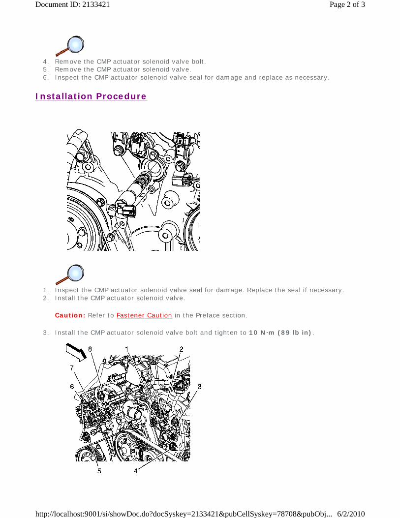
4. Remove the CMP actuator solenoid valve bolt. 5. Remove the CMP actuator solenoid valve. 6. Inspect the CMP actuator solenoid valve seal for damage and replace as necessary.
Installation Procedure
1. Inspect the CMP actuator solenoid valve seal for damage. Replace the seal if necessary. 2. Install the CMP actuator solenoid valve.
Caution: Refer to Fastener Caution in the Preface section.
3. Install the CMP actuator solenoid valve bolt and tighten to 10 N·m (89 lb in).
Page 2 of 3Document ID: 2133421
6/2/2010http://localhost:9001/si/showDoc.do?docSyskey=2133421&pubCellSyskey=78708&pubObj...
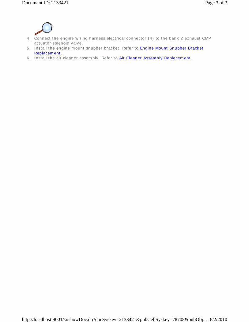
4. Connect the engine wiring harness electrical connector (4) to the bank 2 exhaust CMP
actuator solenoid valve. 5. Install the engine mount snubber bracket. Refer to Engine Mount Snubber Bracket
Replacement. 6. Install the air cleaner assembly. Refer to Air Cleaner Assembly Replacement.
Page 3 of 3Document ID: 2133421
6/2/2010http://localhost:9001/si/showDoc.do?docSyskey=2133421&pubCellSyskey=78708&pubObj...

2009 Chevrolet Malibu | Malibu (VIN Z) Service Manual | Engine | Engine Controls and Fuel - 2.8L, 3.0L, 3.2L, or 3.6L | Repair Instructions | Document ID: 2133425
Knock Sensor Replacement - Bank 1
Removal Procedure
1. Remove the exhaust manifold lower heat shield. Refer to Exhaust Manifold Lower Heat Shield
Replacement. 2. Disconnect the engine wiring harness electrical connector (1) from the bank 1 knock sensor.
3. Loosen the knock sensor bolt and remove the knock sensor.
© 2010 General Motors Corporation. All rights reserved.
Page 1 of 2Document ID: 2133425
6/2/2010http://localhost:9001/si/showDoc.do?docSyskey=2133425&pubCellSyskey=123243&pubO...
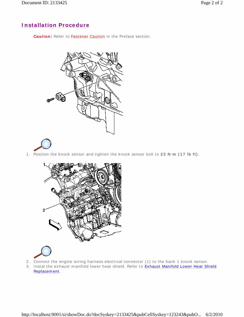
Installation Procedure
Caution: Refer to Fastener Caution in the Preface section.
1. Position the knock sensor and tighten the knock sensor bolt to 23 N·m (17 lb ft).
2. Connect the engine wiring harness electrical connector (1) to the bank 1 knock sensor. 3. Instal the exhaust manifold lower heat shield. Refer to Exhaust Manifold Lower Heat Shield
Replacement.
Page 2 of 2Document ID: 2133425
6/2/2010http://localhost:9001/si/showDoc.do?docSyskey=2133425&pubCellSyskey=123243&pubO...

2009 Chevrolet Malibu | Malibu (VIN Z) Service Manual | Engine | Engine Controls and Fuel - 2.8L, 3.0L, 3.2L, or 3.6L | Repair Instructions | Document ID: 2133428
Knock Sensor Replacement - Bank 2
Removal Procedure
1. Raise and support the vehicle. Refer to Lifting and Jacking the Vehicle. 2. Disconnect the engine wiring harness electrical connector (2) from the bank 2 knock sensor.
3. Loosen the knock sensor bolt and remove the knock sensor.
Installation Procedure © 2010 General Motors Corporation. All rights reserved.
Page 1 of 2Document ID: 2133428
6/2/2010http://localhost:9001/si/showDoc.do?docSyskey=2133428&pubCellSyskey=123244&pubO...
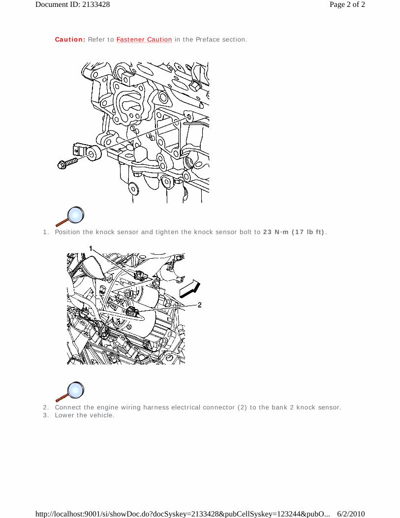
Caution: Refer to Fastener Caution in the Preface section.
1. Position the knock sensor and tighten the knock sensor bolt to 23 N·m (17 lb ft).
2. Connect the engine wiring harness electrical connector (2) to the bank 2 knock sensor. 3. Lower the vehicle.
Page 2 of 2Document ID: 2133428
6/2/2010http://localhost:9001/si/showDoc.do?docSyskey=2133428&pubCellSyskey=123244&pubO...
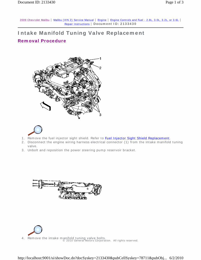
2009 Chevrolet Malibu | Malibu (VIN Z) Service Manual | Engine | Engine Controls and Fuel - 2.8L, 3.0L, 3.2L, or 3.6L | Repair Instructions | Document ID: 2133430
Intake Manifold Tuning Valve Replacement
Removal Procedure
1. Remove the fuel injector sight shield. Refer to Fuel Injector Sight Shield Replacement. 2. Disconnect the engine wiring harness electrical connector (1) from the intake manifold tuning
valve. 3. Unbolt and reposition the power steering pump reservoir bracket.
4. Remove the intake manifold tuning valve bolts.
© 2010 General Motors Corporation. All rights reserved.
Page 1 of 3Document ID: 2133430
6/2/2010http://localhost:9001/si/showDoc.do?docSyskey=2133430&pubCellSyskey=78711&pubObj...
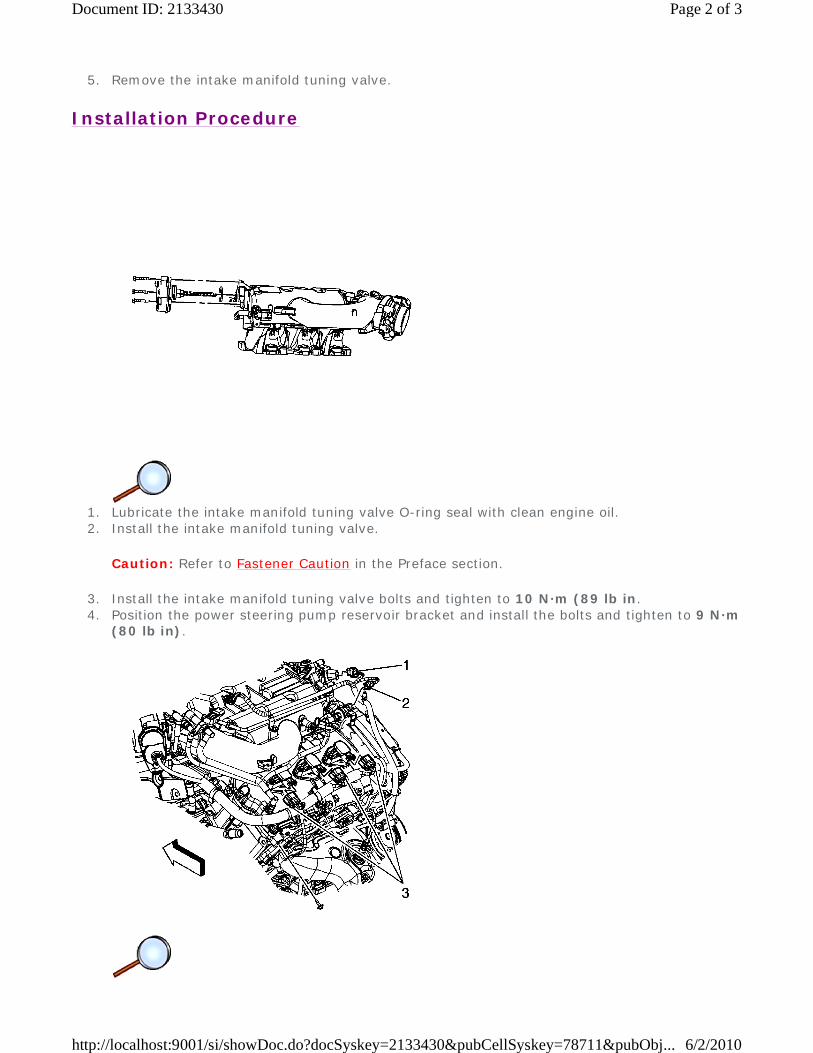
5. Remove the intake manifold tuning valve.
Installation Procedure
1. Lubricate the intake manifold tuning valve O-ring seal with clean engine oil. 2. Install the intake manifold tuning valve.
Caution: Refer to Fastener Caution in the Preface section.
3. Install the intake manifold tuning valve bolts and tighten to 10 N·m (89 lb in. 4. Position the power steering pump reservoir bracket and install the bolts and tighten to 9 N·m
(80 lb in).
Page 2 of 3Document ID: 2133430
6/2/2010http://localhost:9001/si/showDoc.do?docSyskey=2133430&pubCellSyskey=78711&pubObj...
5. Connect the engine wiring harness electrical connector (1) to the intake manifold tuning valve.
6. Install the fuel injector sight shield. Refer to Fuel Injector Sight Shield Replacement.
Page 3 of 3Document ID: 2133430
6/2/2010http://localhost:9001/si/showDoc.do?docSyskey=2133430&pubCellSyskey=78711&pubObj...
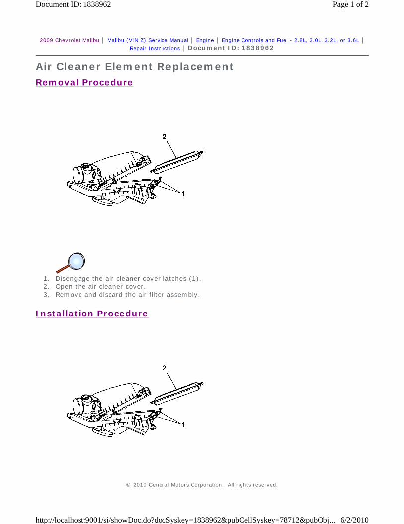
2009 Chevrolet Malibu | Malibu (VIN Z) Service Manual | Engine | Engine Controls and Fuel - 2.8L, 3.0L, 3.2L, or 3.6L | Repair Instructions | Document ID: 1838962
Air Cleaner Element Replacement
Removal Procedure
1. Disengage the air cleaner cover latches (1). 2. Open the air cleaner cover. 3. Remove and discard the air filter assembly.
Installation Procedure
© 2010 General Motors Corporation. All rights reserved.
Page 1 of 2Document ID: 1838962
6/2/2010http://localhost:9001/si/showDoc.do?docSyskey=1838962&pubCellSyskey=78712&pubObj...
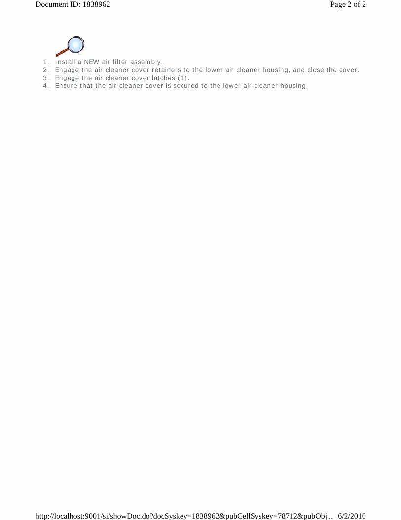
1. Install a NEW air filter assembly. 2. Engage the air cleaner cover retainers to the lower air cleaner housing, and close the cover. 3. Engage the air cleaner cover latches (1). 4. Ensure that the air cleaner cover is secured to the lower air cleaner housing.
Page 2 of 2Document ID: 1838962
6/2/2010http://localhost:9001/si/showDoc.do?docSyskey=1838962&pubCellSyskey=78712&pubObj...
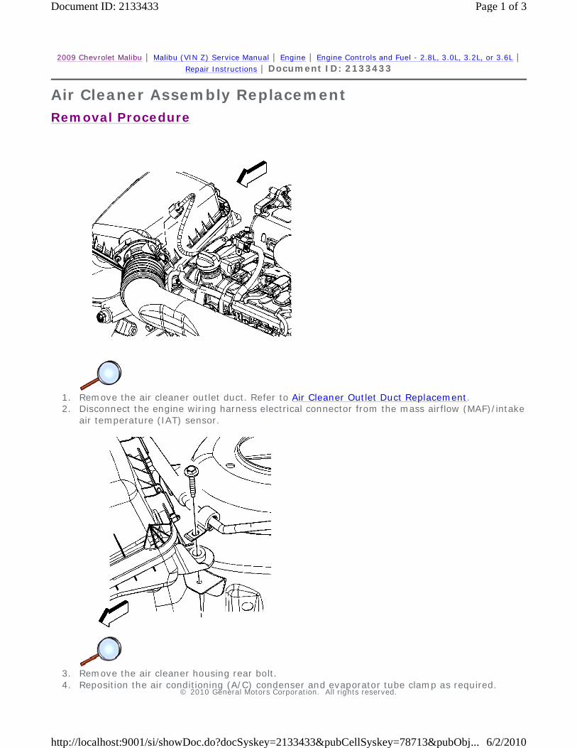
2009 Chevrolet Malibu | Malibu (VIN Z) Service Manual | Engine | Engine Controls and Fuel - 2.8L, 3.0L, 3.2L, or 3.6L | Repair Instructions | Document ID: 2133433
Air Cleaner Assembly Replacement
Removal Procedure
1. Remove the air cleaner outlet duct. Refer to Air Cleaner Outlet Duct Replacement. 2. Disconnect the engine wiring harness electrical connector from the mass airflow (MAF)/intake
air temperature (IAT) sensor.
3. Remove the air cleaner housing rear bolt. 4. Reposition the air conditioning (A/C) condenser and evaporator tube clamp as required.
© 2010 General Motors Corporation. All rights reserved.
Page 1 of 3Document ID: 2133433
6/2/2010http://localhost:9001/si/showDoc.do?docSyskey=2133433&pubCellSyskey=78713&pubObj...
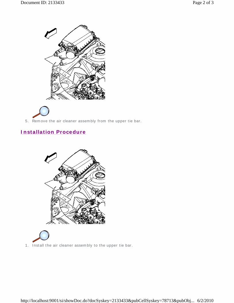
5. Remove the air cleaner assembly from the upper tie bar.
Installation Procedure
1. Install the air cleaner assembly to the upper tie bar.
Page 2 of 3Document ID: 2133433
6/2/2010http://localhost:9001/si/showDoc.do?docSyskey=2133433&pubCellSyskey=78713&pubObj...
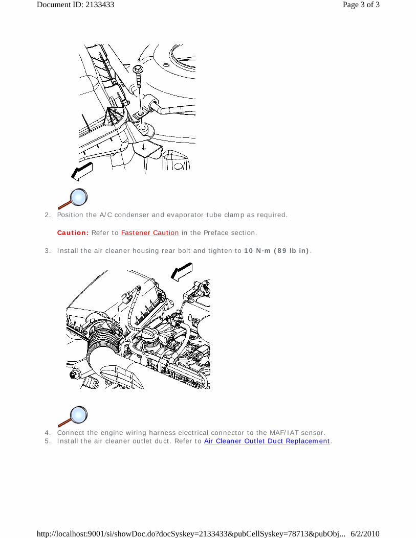
2. Position the A/C condenser and evaporator tube clamp as required.
Caution: Refer to Fastener Caution in the Preface section.
3. Install the air cleaner housing rear bolt and tighten to 10 N·m (89 lb in).
4. Connect the engine wiring harness electrical connector to the MAF/IAT sensor. 5. Install the air cleaner outlet duct. Refer to Air Cleaner Outlet Duct Replacement.
Page 3 of 3Document ID: 2133433
6/2/2010http://localhost:9001/si/showDoc.do?docSyskey=2133433&pubCellSyskey=78713&pubObj...
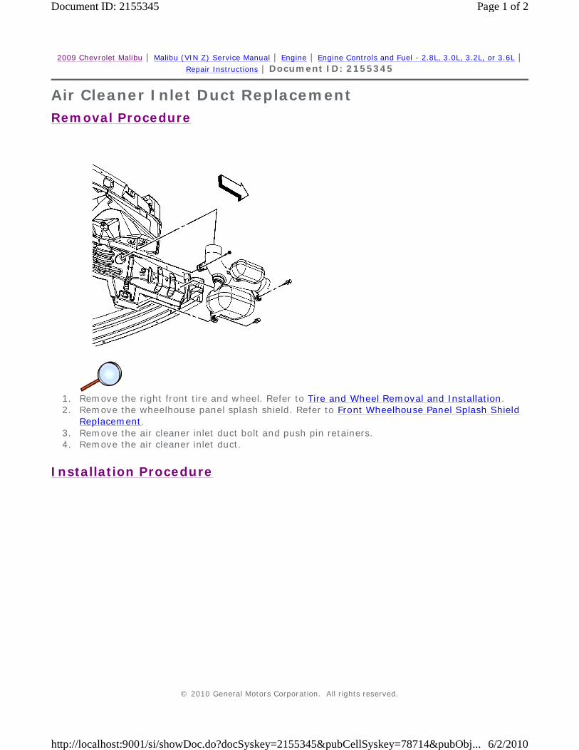
2009 Chevrolet Malibu | Malibu (VIN Z) Service Manual | Engine | Engine Controls and Fuel - 2.8L, 3.0L, 3.2L, or 3.6L | Repair Instructions | Document ID: 2155345
Air Cleaner Inlet Duct Replacement
Removal Procedure
1. Remove the right front tire and wheel. Refer to Tire and Wheel Removal and Installation. 2. Remove the wheelhouse panel splash shield. Refer to Front Wheelhouse Panel Splash Shield
Replacement. 3. Remove the air cleaner inlet duct bolt and push pin retainers. 4. Remove the air cleaner inlet duct.
Installation Procedure
© 2010 General Motors Corporation. All rights reserved.
Page 1 of 2Document ID: 2155345
6/2/2010http://localhost:9001/si/showDoc.do?docSyskey=2155345&pubCellSyskey=78714&pubObj...
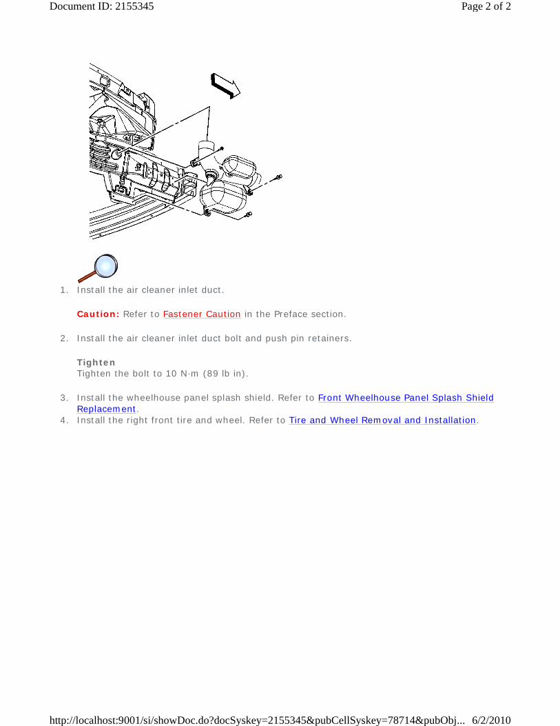
1. Install the air cleaner inlet duct.
Caution: Refer to Fastener Caution in the Preface section.
2. Install the air cleaner inlet duct bolt and push pin retainers.
Tighten Tighten the bolt to 10 N·m (89 lb in).
3. Install the wheelhouse panel splash shield. Refer to Front Wheelhouse Panel Splash Shield Replacement.
4. Install the right front tire and wheel. Refer to Tire and Wheel Removal and Installation.
Page 2 of 2Document ID: 2155345
6/2/2010http://localhost:9001/si/showDoc.do?docSyskey=2155345&pubCellSyskey=78714&pubObj...
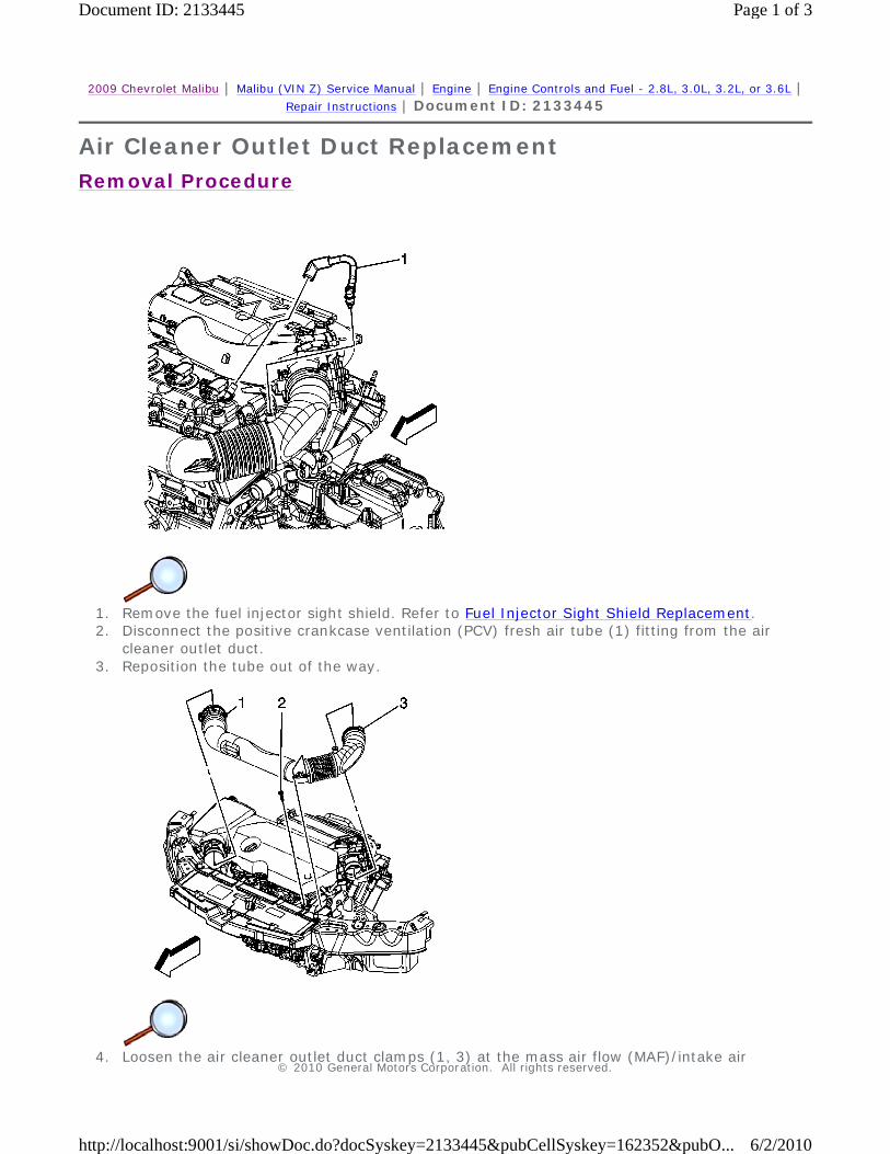
2009 Chevrolet Malibu | Malibu (VIN Z) Service Manual | Engine | Engine Controls and Fuel - 2.8L, 3.0L, 3.2L, or 3.6L | Repair Instructions | Document ID: 2133445
Air Cleaner Outlet Duct Replacement
Removal Procedure
1. Remove the fuel injector sight shield. Refer to Fuel Injector Sight Shield Replacement. 2. Disconnect the positive crankcase ventilation (PCV) fresh air tube (1) fitting from the air
cleaner outlet duct. 3. Reposition the tube out of the way.
4. Loosen the air cleaner outlet duct clamps (1, 3) at the mass air flow (MAF)/intake air
© 2010 General Motors Corporation. All rights reserved.
Page 1 of 3Document ID: 2133445
6/2/2010http://localhost:9001/si/showDoc.do?docSyskey=2133445&pubCellSyskey=162352&pubO...

temperature (IAT) sensor and throttle body. 5. Remove the air cleaner outlet duct bolt (2). 6. Remove the air cleaner outlet duct.
Installation Procedure
1. Position and install the air cleaner outlet duct to the MAF/IAT sensor and the throttle body.
Caution: Refer to Fastener Caution in the Preface section.
2. Install the air cleaner outlet duct bolt (2) and tighten to 10 N·m (89 lb in). 3. Tighten the air cleaner outlet duct clamps (1, 3) at the MAF/IAT sensor and throttle body to
4 N·m (35 lb in).
Page 2 of 3Document ID: 2133445
6/2/2010http://localhost:9001/si/showDoc.do?docSyskey=2133445&pubCellSyskey=162352&pubO...

4. Position the PCV tube. 5. Connect the PCV fresh air tube (1) quick connect fitting to the air cleaner outlet duct. 6. Install the fuel injector sight shield. Refer to Fuel Injector Sight Shield Replacement.
Page 3 of 3Document ID: 2133445
6/2/2010http://localhost:9001/si/showDoc.do?docSyskey=2133445&pubCellSyskey=162352&pubO...