Embed Size (px)
DESCRIPTION
Engine Alternator Repower Giude
Citation preview
MS-0415-02/11
BRIGGS&STRATTONCORPORATION
CUSTOMER EDUCATION POST OffICE bOx 702MIlwAUkEE, wI 53201 USA800 934 7730 | [email protected] ©2011. All rights reserved.
Printed in the U.S.A.
BRITISH COLUMBIAALBERTA
SASKATCHEWAN MANITOBA
ONTARIO QUEBEC
Magneto Power
Atlantic Power
MWE
Central Power Systems
Preferred Power
SEDCO
EDWARDSVILLE
WEST VALLEY CITY
ANOKA
COLUMBUS
DELTA
Power Source Canada
9/09
CASTLETON
PENDERGRASS
MEQUON
OAKVILLE
IDN Network
TUALATINA
1. Magneto Power, LLC anoka (Minneapolis) Mn 55303 Magneto Power, LLC 911 Lund Boulevard, Suite 300 robert Moe 800-248-4016
Dallas tX 75235 Magneto Power, LLC of texas 11011 regency Crest Drive, Suite 100 robert ortolani 262-834-4394
Mequon (Milwaukee) wI 53092 Magneto Power, LLC 1000 w. Donges Bay road, Suite 100 robert Moe 262-834-4300
tualatin (Portland) or 97062 Magneto Power, LLC “west” 9991 S.w. avery Street greg Muse 800-338-5168
2. MIDweSt engIne wareHoUSe aurora (Chicago) IL 60504 Midwest engine warehouse-IL 700 enterprise Street tom Ziemann 630-862-3100
edwardsville (KC) KS 66111 Midwest engine warehouse-KS 9630 woodend road tom Ziemann 913-543-7600
Visalia Ca 93291 Midwest engine warehouse-Ca 7101 w. Doe avenue John reid 800-683-8484
west Valley City (SLC) Ut 84120 Midwest engine warehouse-Ut 3626 Parkway Boulevard tom Ziemann 801-886-2350
3. PreFerreD Power, InC Charlotte nC 28216 Preferred Power, Inc. 6509-a northpark Boulevard Steve Krcelic 800-288-5310
4. Power SoUrCe CanaDa, LtD Delta (Vancouver) BC V3M 6r9 Power Source Canada, LtD 300-1628 Derwent way Mike gulley 604-520-1294
oakville (toronto) on L6H 6X5 Power Source Canada, LtD 2815 Bristol Circle, Unit 1 Mike gulley 905-829-0006
5. atLantIC Power, InC Castleton nY 12033 atlantic Power, Inc. 20 empire State Boulevard art Falk 800-456-5692
6. CentraL Power SYSteMS Columbus oH 43228 Central Power Systems 3700 Paragon Drive Pat earnest 614-534-2152
tampa FL 33610 Central Power Systems of Florida
4751 oak Fair Boulevard ray Coyle 614-534-2140
7. SeDCo, InC Pendergrass (atlanta) ga 30567 SeDCo, Inc. 225 Henry D. robertson Boulevard wayne Crosby 800-346-4260
Pendergrass (atlanta) ga 30567 SeDCo, Inc. 225 Henry D. robertson Boulevard Mark thomas 800-346-4260
CSSD / IDN EDUCATIONAL DIRECTORS
01/11
ENGINEALTERNATOR
REPOWER GUIDE
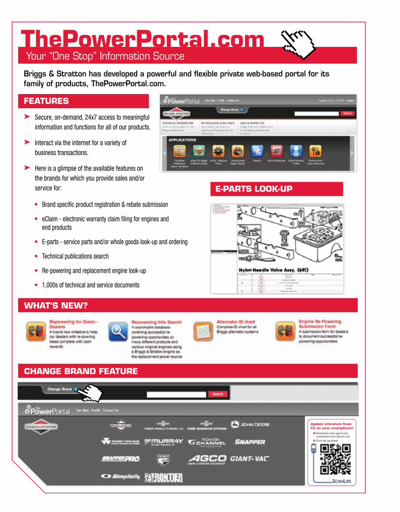
Briggs & Stratton has developed a powerful and flexible private web-based portal for its family of products, ThePowerPortal.com.
Features
➤ Secure, on-demand, 24x7 access to meaningful information and functions for all of our products.
➤ Interact via the internet for a variety of business transactions.
➤ Here is a glimpse of the available features on the brands for which you provide sales and/or service for:
• Brand specific product registration & rebate submission
• eClaim - electronic warranty claim filing for engines and end products
• E-parts - service parts and/or whole goods look-up and ordering
• Technical publications search
• Re-powering and replacement engine look-up
• 1,000s of technical and service documents
Your “One Stop” Information SourceYour “One Stop” Information SourcethePowerPortal.com
e-Parts Look-uP
what’s new?
ChanGe BranD FeatureUpdate Literature from CE on your smartphone!
Download a free app to your phone from 2dscan.com Scan the tag to right. No smartphone?
Text XXXXXXXX to 00000. Standard data rates may apply.
Update Literature fromCE on your smartphone!
Download a free app to your smartphone from 2dscan.com
Scan the tag below
BRIGGS & STRATTON ALTERNATOR CHART
(10 A.)160000170000190000220000250000280000290000303000310000320000330000350000380000400000420000460000(13 A.)400000420000
(16 A.)220000250000280000290000303000310000320000350000380000400000420000460000(QUAD)170000190000220000250000280000460000
Engine 14 Amp Regulated AlternatorEngine430000520000580000
14 Amp DC regulated
Engine35X700
115 Volts 60 Hz, 13 Amp DC regulated
Engine35X400
115 Volts 60 Hz,13 Amp DC regulated
Engine110000120000200000210000
10 Amp DC regulated
Engine170000190000210000220000240000250000280000300000310000326000350000380000
2 - 4 Amp DC unregulatedEngine90000110000
397880
White Connector1 Black Wire
Since 1981Alternator outside the flywheel
System 3® / System 4®0.5 Amp DC unregulated
Output @ 2800 rpm
Engine9770099700100600100800110000120000
691991794103
White Connector1 Black Wire
Since 1989 Alternator outside the flywheel
0.5 Amp DC unregulatedOutput @ 2800 rpm
Engine104700130000
494254
Red Connector1 Black Wire
Since 1988
1.2 Amp DC unregulated
Engine110000120000200000210000
695730
RedConnector
1 Red Wire
Since 2000
3 Amp DC unregulated
696578 Since 1973
Engine110000120000150000200000
694457
White Connector1 Red Wire
Engine201000210000
698230
White Connector1Black Wire1 Red Wire
Since 2002
2 – 4 Amp DC / 5 Amp AC14 Volts AC unregulated
4 Amp Regulated Alternator
715194
Yellow Connector399916 Shipped loose
2 Green Wires
715262 Since 1988695466Since 2000Small magnets
Yellow Connector2 Yellow Wires
Red Connector1 Red Wire
691185
Yellow Connector2 Black Wires
841178 Since 2004
20 - 50 Amp Regulated/ Inverter Alternator
2 White Connector 4 Yellow Wires, 1 Red Wire
2 White Connectors2 Yellow Wires each
Engine430000520000580000
825084825524
Since 2000Since 2002
40 Amp Alternator40 Amp DC regulated
Flywheel / Magnets
Engine130200
394250
3 Amp DC unregulated
Engine110000120000150000200000210000280000300000
698314 Since 2002
5 or 9 Amp regulated, Tri-circuit
5 or 9 Amp Regulated Alternator
Engine150000201000210000
696742
White Connector1 Black Wire, 1 Red Wire
Since 2002
2 – 4 Amp DC / 5 Amp AC14 Volts AC unregulated
Engine120000
790320 Since 2004
10 Amp DC regulatedHigh Output
Engine170000190000210000220000240000250000280000300000310000326000350000380000
393809
2 - 4 Amp DC unregulated
715255Since 1994 Small magnets
5 or 9 Amp Regulated or Tri-circuit Alternator Engine160000170000190000210000220000250000256000280000290000300000310000320000330000350000380000400000420000440000460000696457 Since 1988 (5 & 9 Amp)
1976 Tri-circuit
Green Connector 1 Yellow Wire
Red Connector 1 Red WireSmall magnet 28 Volts AC 5 Amp DC regulatedLarge magnet 40 Volts AC 9 Amp DC regulated
691188
5 or 9 Amp DC regulated, Tri-circuit
10 A Since 197813 A Since 197916 A Since 1983Quad Circuit Since 1984
Engine115400117400118000185400187400
4 Amp DC regulated
Engine117400138400185400
Engine23X40024X400
715798
10 Amp DC regulated
Engine290000300000350000380000470000540000
20 -50 Amp DC regulated
White Connector2 Yellow Wires
1 Red Wire
White Connector2 Yellow Wires, 1 Red Wire
Engine290000303000310000350000351000380000470000540000610000
20 Amp DC regulated
696579Since 1995Large magnets
Engine44X700
697810 Since 2002
825004
Engine430000520000580000
825479825577
60 Amp Alternator
10, 13, 16 Amp DC regulated, Quad-Circuit (regulated battery charge but unregulated lights)
Yellow Connector 2 Yellow Wires
Double White Connector 1 Red Wire (charge)
1 Blue Wire (charge indicator light)
Yellow Connector 2 Yellow Wires
White Connector Black Wire = 8 Amp DC unregulated for lightsRed Wire = 8 Amp DC regulated for batterySmall magnets Quad Circuit 20 Volts AC @ stator
493219
696458
Brass ConnectorPlastic sleeves Green Wires to regulator, 1 Green, 1 Red between Armatures
10 Amp DC regulated
Since 1974 Medium magnets
Yellow Connector 399916 To be ordered separately
Green Wires
Engine230400240400
Red Connector2 Red Wires, 1 Black Wire
Green Connector1 Black Wire
Black Connector 2 Black Wires
No Connector2 Black Wires
2 Blue Wires
2 - 4 Amp DC unregulated
10 Amp DC regulated
White Connector2 Yellow Wires
Black Connector2 Red Wires, 1 Green Wire
841588 Since 2007
Yellow Connector2 Black Wires
Black Connector2 Red Wires, 1 Green Wire
White Connector2 Yellow Wires
Black Connector2 Red Wires, 1 Green Wire
841833 Since 2007
Engine305000356000
115 Volts 60 Hz, 13 Amp DC regulated
809175 Since 2007
Black Connector2 Black Wires
793658795498 Since 2007
790325
793660
2 Black Connectors 2 Black Wires, 1 Red Wire
Engine20H40021A400
20 Amp DC regulated
Green ConnectorBlack Wire
697992
691573
60 Amp DC regulated
Red Connector1 Red Wire
Green Connector1 Yellow Wire Red Connector 1 Red WireSmall magnet 28 Volts AC 5 Amp DC regulatedLarge magnet 40 Volts AC 9 Amp DC regulated
2 Black Connectors 2 Black Wires, 1 Red Wire
White Connector Black ConnectorIvory sheathed wires
Orange Connector1 Orange Wire
Black Connector1 Black Wire
691955
1 Red Wire691362
www.thepowerportal.com
Diode 391507
Diode 391507
Diode 391507
Diode 391507
Engine17000019000021000022000024000025000028000029000030000031000032000033000035000038000046X700
696459
White Connector1 Black Wire, 1 Red Wire
Since 2007
2 – 4 Amp DC / 5 Amp AC14 Volts AC unregulated
Engine15X00020X00021X000
793118795498 Since 2007
2 – 4 Amp DC / 5 Amp AC14 Volts AC unregulated
Diode 391507
Since 1979
Since 1999 Since 1978
Since 2001
Since 1998
Since 2002Since 2002
115 Volts - 60 Hz, 13 Amp DC regulated
790325
Diode 391507
Diode 391507
Diode 391507
790292
2 WhiteConnectors1 Red Wire1 Yellow Wire 1 Black Wire
790292
2 WhiteConnectors 1 Red Wire1 Yellow Wire1 Black Wire
790292
2 White Connectors1 Red Wire 1 Yellow Wire 1 Black Wire
790292
2 White Connectors 1 Red Wire1 Yellow Wire 1 Black Wire
White Connector1 Black Wire, 1 Red Wire
715200Tri-circuit Diode Wire
Green Connectorwith 2 diodes leading to 1 Red Wire and
1 White WireRed Wire = 2-5 Amp DC unregulated for
battery chargeWhite Wire = 2-5 Amp DC negative for lights
Yellow Connector2 Yellow Wires
Red Connector 1 Red Wire
691185
Yellow Connector 2 Yellow Wires
Red Connector 1 Red Wire
Yellow Connector2 Black Wires
White Sheath 1 Blue WireWhite Connector 2 Red WireBlack ConnectorWhite ConnectorYellow Sheath 1 White Wire,1 Black Wire, 1 Green Wire
Yellow Connector 2 Yellow WiresRed Connector Red WireSmall Magnets = 20 Volts AC @ stator and10 Amp DC regulatedMedium Magnets = 20 Volts AC @ statorand 13 Amp DC regulatedLarge Magnets = 30 Volts AC @ stator and16 Amp DC regulated
841170
10, 13 and 16 A DC Regulated or Quad Circuit Alternator
Diode 391507 Diode
391507
DC only Alternator
Dual circuit Alternator
10 Amp Alternator
20 Amp Regulated Alternator
691188794360
691185
Engine110000120000200000
791743 Since 2007
0.5 Amp DC unregulated
White Connector1 Red Wire
391595
White Connector1 Black Wire
Since 1974Small magnets
AC only Alternator14 Volts ACunregulated
Engine160000170000190000210000220000243000250000280000310000320000400000420000460000
13 Amp Power Link™ Alternator
697261 Orange Connector1 Orange Wire
Black Connector 1 Black Wire
697992
White Connector 1 Blue Wire,White Connector 2 Red Wires,Black ConnectorWhite ConnectorYellow Sheath 1 White Wire, 1 Black Wire, 1 Green Wire
697261
Connector Orange 1 Orange Wire
Black Connector 1 Black Wire
697992White Connector 1 Blue WireWhite Connector 2 Red WiresBlack ConnectorWhite ConnectorYellow Sheath 1 White Wire,1 Black Wire, 1 Green Wire
697261
Orange Connector1 Orange Wire
Black Connector 1 Black Wire
697992
White Connector 1 Blue WireWhite Connector 2 Red WiresBlack ConnectorWhite ConnectorYellow Sheath 1 White Wire, 1 Black Wire, 1 Green Wire
Engine12X40015X40020X40021X400
793640 Since 2007
1.5 Amp DC unregulated
White Connector1 Black Wire
Diode 391507
DC only Alternator
Yellow Connector 2 Yellow Wires
Red Connector 1 Red Wire
691185
White Connector2 Yellow Wires
White Connector1 Red Wire, 1 Brown Wire,
1 Orange Wirecharge indicator light
809176
2 Black Connectors 2 Black Wires 1 Red Wire
White Connector2 Yellow Wires,
1 Red Wire
691573
697261
White Connector2 Yellow Wires
1 Red Wire
691573
Red Connector1 Red Wire
Yellow Connector1 Red Wire, 2 Green Wires, 1 Black Wire
• SMALL: 7/8” x 11/16” (22 x 18 mm)
• MEDIUM: 1-1/16” x 11/16” (27 x 18 mm)
• LARGE: 1-1/16” x 15/16” (27 x 24 mm)
For Engine Series V TWIN VANGUARD™:
• SMALL: 7/8” x 21/32” (22 x 17 mm)
• MEDIUM: 7/8” x 29/32” (22 x 23 mm)
• LARGE: 1-3/32” x 29/32” (28 x 23 mm)
Note : Unless specified, all tests must be carried out with the engine running at 3600 rpm.The values indicated are minimium values. If the value measured is lower thanindicated a repeat test is advised before proceding any further.
698315 698315
794360
825003
White Connector 1 Red Wire1 Black Wire1 Yellow Wire2 Blue Wires1 Green Wire
Yellow Connector2 Yellow Wires
White Connector1 Brown Wire1 Orange Wire1 Red Wire
808877
397809
691185
MS-2288FL - 11/08
MS-2288FL.qxp 10/23/2008 10:24 Page 1
Briggs & stratton alternator Chart
You can order this chart from your source of supply or on ThePowerPortal.com under Customer Education.
1
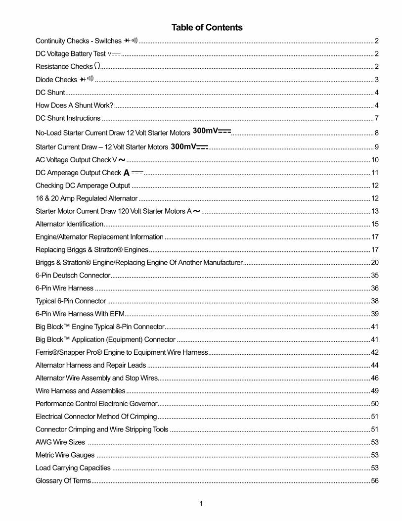
Table of ContentsContinuity Checks ‑ Switches .......................................................................................................................................2
DC Voltage Battery Test V .................................................................................................................................................2
Resistance Checks .............................................................................................................................................................2
Diode Checks ................................................................................................................................................................3
DC Shunt .................................................................................................................................................................................4
How Does A Shunt Work? .....................................................................................................................................................4
DC Shunt Instructions ............................................................................................................................................................7
No‑Load Starter Current Draw 12 Volt Starter Motors 300mV ..................................................................................8
Starter Current Draw – 12 Volt Starter Motors 300mV ...............................................................................................9
AC Voltage Output Check V ............................................................................................................................................10
DC Amperage Output Check ..................................................................................................................................11
Checking DC Amperage Output .........................................................................................................................................12
16 & 20 Amp Regulated Alternator .....................................................................................................................................12
Starter Motor Current Draw 120 Volt Starter Motors A .................................................................................................13
Alternator Identification .........................................................................................................................................................15
Engine/Alternator Replacement Information ......................................................................................................................17
Replacing Briggs & Stratton® Engines ...............................................................................................................................17
Briggs & Stratton® Engine/Replacing Engine Of Another Manufacturer .........................................................................20
6‑Pin Deutsch Connector .....................................................................................................................................................35
6‑Pin Wire Harness ..............................................................................................................................................................36
Typical 6‑Pin Connector .......................................................................................................................................................38
6‑Pin Wire Harness With EfM .............................................................................................................................................39
Big Block™ Engine Typical 8‑Pin Connector ......................................................................................................................41
Big Block™ Application (Equipment) Connector ...............................................................................................................41
ferris®/Snapper Pro® Engine to Equipment Wire Harness .............................................................................................42
Alternator Harness and Repair Leads ................................................................................................................................44
Alternator Wire Assembly and Stop Wires..........................................................................................................................46
Wire Harness and Assemblies ............................................................................................................................................49
Performance Control Electronic Governor ..........................................................................................................................50
Electrical Connector Method Of Crimping ..........................................................................................................................51
Connector Crimping and Wire Stripping Tools ...................................................................................................................51
AWG Wire Sizes ..................................................................................................................................................................53
Metric Wire Gauges .............................................................................................................................................................53
Load Carrying Capacities ....................................................................................................................................................53
Glossary Of Terms ................................................................................................................................................................56
2
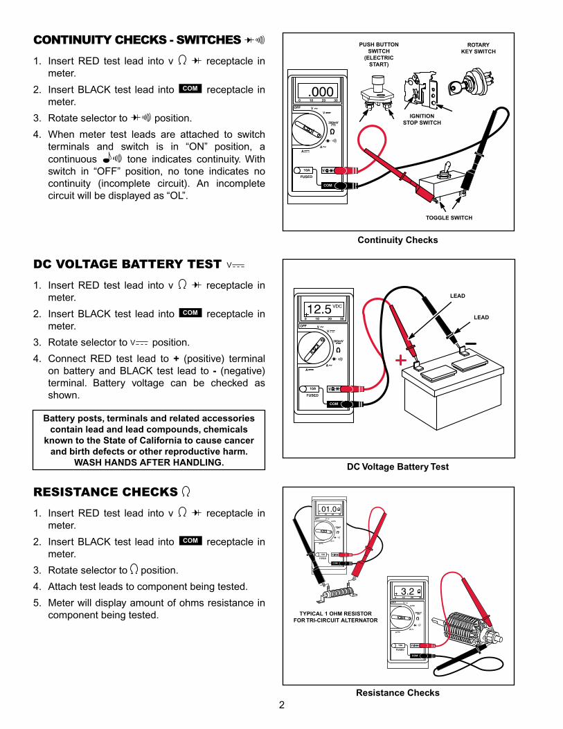
RESISTANCE CHECKS
1. Insert RED test lead into v receptacle in meter.
2. Insert BLACK test lead into COM receptacle in meter.
3. Rotate selector to position.
4. Attach test leads to component being tested.
5. Meter will display amount of ohms resistance in component being tested.
Continuity Checks
DC Voltage Battery Test
Resistance Checks
CONTINUITY CHECKS ‑ SWITCHES 1. Insert RED test lead into v receptacle in
meter.
2. Insert BLACK test lead into COM receptacle in meter.
3. Rotate selector to position.
4. When meter test leads are attached to switch terminals and switch is in “ON” position, a continuous tone indicates continuity. With switch in “Off” position, no tone indicates no continuity (incomplete circuit). An incomplete circuit will be displayed as “OL”.
DC VOLTAGE BATTERY TEST V
1. Insert RED test lead into v receptacle in meter.
2. Insert BLACK test lead into COM receptacle in meter.
3. Rotate selector to V position.
4. Connect RED test lead to + (positive) terminal on battery and BLACK test lead to - (negative) terminal. Battery voltage can be checked as shown.
PUSH BUTTON SWITCH
(ELECTRIC START)
ROTARY KEY SWITCH
IGNITION STOP SWITCH
TOGGLE SWITCH
LEAD
LEAD
TYPICAL 1 OHM RESISTOR FOR TRI-CIRCUIT ALTERNATOR
Battery posts, terminals and related accessoriescontain lead and lead compounds, chemicals
known to the State of California to cause cancer and birth defects or other reproductive harm.
WASH HANDS AFTER HANDLING.
3
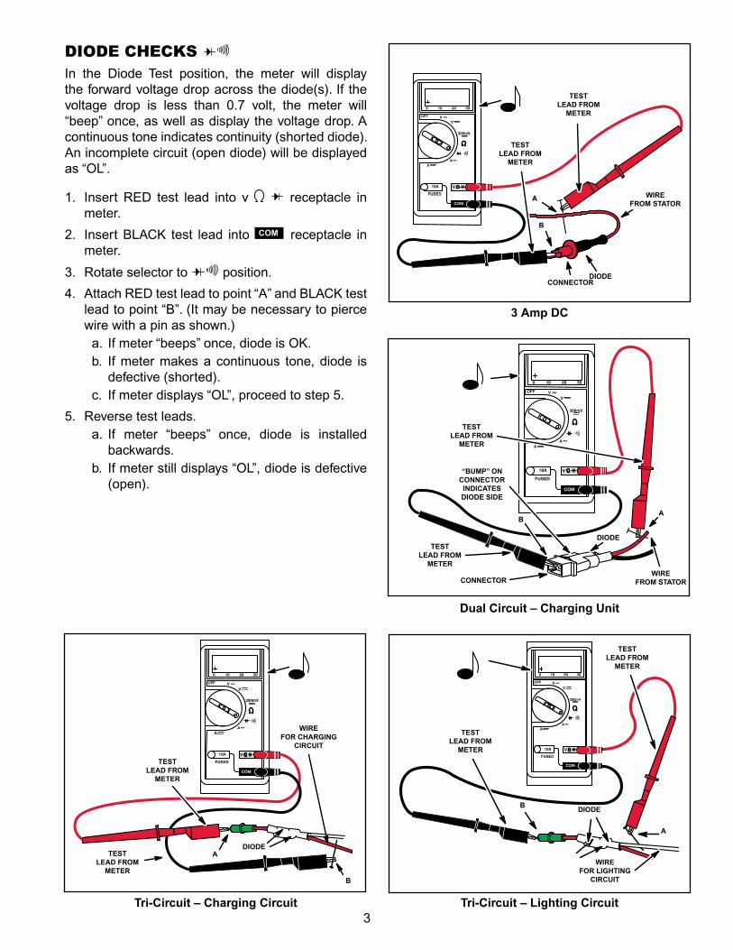
DIODE CHECKS In the Diode Test position, the meter will display the forward voltage drop across the diode(s). If the voltage drop is less than 0.7 volt, the meter will “beep” once, as well as display the voltage drop. A continuous tone indicates continuity (shorted diode). An incomplete circuit (open diode) will be displayed as “OL”.
1. Insert RED test lead into v receptacle in meter.
2. Insert BLACK test lead into COM receptacle in meter.
3. Rotate selector to position.
4. Attach RED test lead to point “A” and BLACK test lead to point “B”. (It may be necessary to pierce wire with a pin as shown.)
a. If meter “beeps” once, diode is OK.b. If meter makes a continuous tone, diode is
defective (shorted).c. If meter displays “OL”, proceed to step 5.
5. Reverse test leads. a. If meter “beeps” once, diode is installed
backwards. b. If meter still displays “OL”, diode is defective
(open).
Dual Circuit – Charging Unit
3 Amp DC
TEST LEAD FROM
METER
TEST LEAD FROM
METER
WIRE FROM STATOR
CONNECTORDIODE
A
B
AB
WIRE FROM STATOR
DIODETEST
LEAD FROM METER
CONNECTOR
“BUMP” ON CONNECTOR INDICATES DIODE SIDE
TEST LEAD FROM
METER
Tri-Circuit – Lighting CircuitTri-Circuit – Charging Circuit
A
BDIODE
TEST LEAD FROM
METER
TEST LEAD FROM
METER
WIRE FOR LIGHTING
CIRCUIT
TEST LEAD FROM
METER
DIODEA
WIRE FOR CHARGING
CIRCUIT
TEST LEAD FROM
METER
B
4
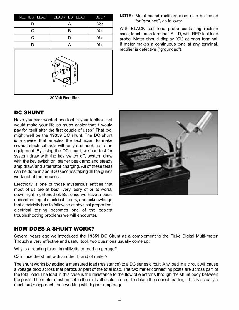
NOTE: Metal cased rectifiers must also be tested for “grounds”, as follows:
With BLACK test lead probe contacting rectifier case, touch each terminal, A – D, with RED test lead probe. Meter should display “OL” at each terminal. If meter makes a continuous tone at any terminal, rectifier is defective (“grounded”).
120 Volt Rectifier
A
B
D
C
RED TEST LEAD BLACK TEST LEAD BEEP
B A Yes
C B Yes
C D Yes
D A Yes
DC SHUNTHave you ever wanted one tool in your toolbox that would make your life so much easier that it would pay for itself after the first couple of uses? That tool might well be the 19359 DC shunt. The DC shunt is a device that enables the technician to make several electrical tests with only one hook‑up to the equipment. By using the DC shunt, we can test for system draw with the key switch off, system draw with the key switch on, starter peak amp and steady amp draw, and alternator charging. All of these tests can be done in about 30 seconds taking all the guess work out of the process.
Electricity is one of those mysterious entities that most of us are at best, very leery of or at worst, down right frightened of. But once we have a basic understanding of electrical theory, and acknowledge that electricity has to follow strict physical properties, electrical testing becomes one of the easiest troubleshooting problems we will encounter.
HOW DOES A SHUNT WORK?Several years ago we introduced the 19359 DC Shunt as a complement to the fluke Digital Multi‑meter. Though a very effective and useful tool, two questions usually come up:
Why is a reading taken in millivolts to read amperage?
Can I use the shunt with another brand of meter?
The shunt works by adding a measured load (resistance) to a DC series circuit. Any load in a circuit will cause a voltage drop across that particular part of the total load. The two meter connecting posts are across part of the total load. The load in this case is the resistance to the flow of electrons through the shunt body between the posts. The meter must be set to the millivolt scale in order to obtain the correct reading. This is actually a much safer approach than working with higher amperage.
5
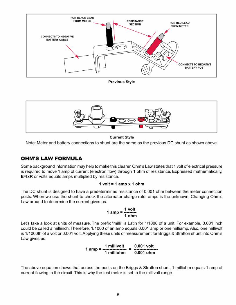
CONNECTS TO NEGATIVE BATTERY CABLE
FOR BLACK LEAD FROM METER RESISTANCE
SECTION FOR RED LEAD FROM METER
CONNECTS TO NEGATIVE BATTERY POST
Previous Style
Current StyleNote: Meter and battery connections to shunt are the same as the previous DC shunt as shown above.
OHM'S LAW FORMULA
Some background information may help to make this clearer. Ohm’s Law states that 1 volt of electrical pressure is required to move 1 amp of current (electron flow) through 1 ohm of resistance. Expressed mathematically, E=IxR or volts equals amps multiplied by resistance.
1 volt = 1 amp x 1 ohm
The DC shunt is designed to have a predetermined resistance of 0.001 ohm between the meter connection posts. When we use the shunt to check the alternator charge rate, amps is the unknown. Changing Ohm’s Law around to determine the current gives us:
1 volt1 amp = ---------
1 ohm
Let’s take a look at units of measure. The prefix “milli” is Latin for 1/1000 of a unit. for example, 0.001 inch could be called a milliinch. Therefore, 1/1000 of an amp equals 0.001 amp or one milliamp. Also, one millivolt is 1/1000th of a volt or 0.001 volt. Applying these units of measurement for Briggs & Stratton shunt into Ohm’s Law gives us:
1 millivolt 0.001 volt1 amp = ----------------- = -----------------
1 milliohm 0.001 ohm
The above equation shows that across the posts on the Briggs & Stratton shunt, 1 milliohm equals 1 amp of current flowing in the circuit. This is why the test meter is set to the millivolt range.
6
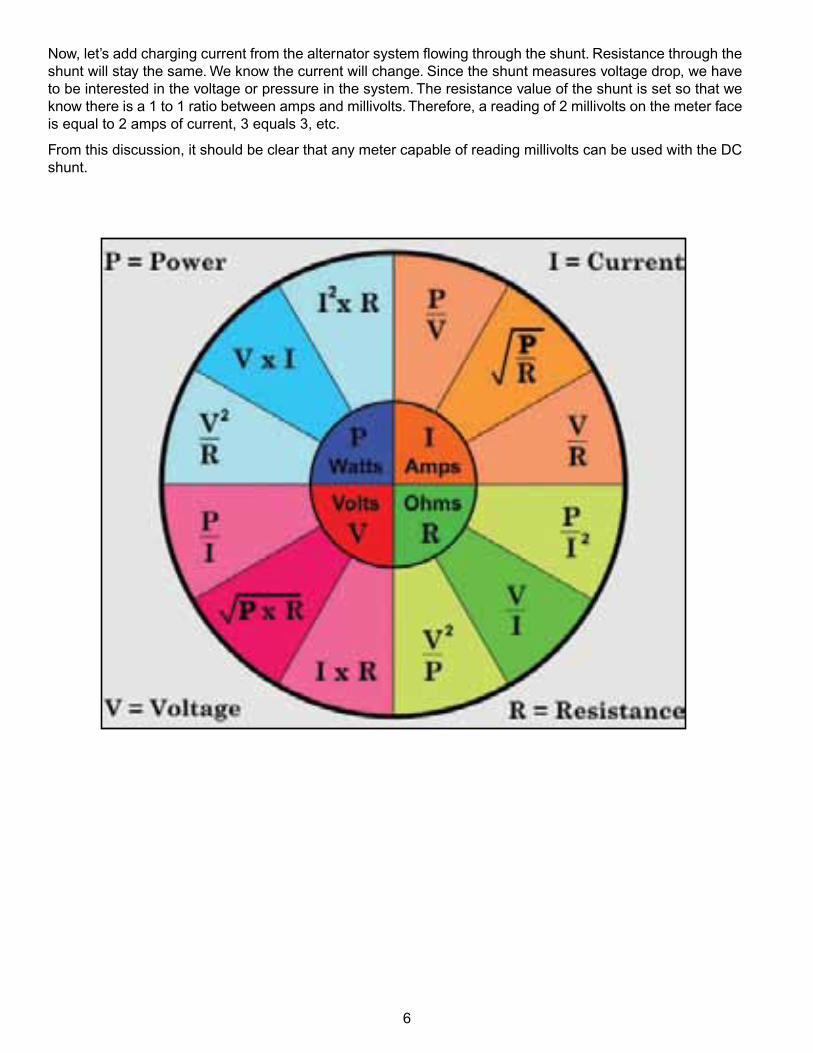
Now, let’s add charging current from the alternator system flowing through the shunt. Resistance through the shunt will stay the same. We know the current will change. Since the shunt measures voltage drop, we have to be interested in the voltage or pressure in the system. The resistance value of the shunt is set so that we know there is a 1 to 1 ratio between amps and millivolts. Therefore, a reading of 2 millivolts on the meter face is equal to 2 amps of current, 3 equals 3, etc.
from this discussion, it should be clear that any meter capable of reading millivolts can be used with the DC shunt.
7
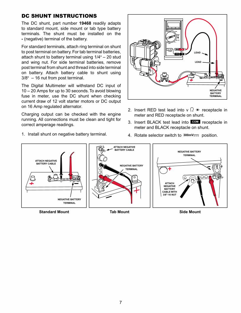
DC SHUNT INSTRUCTIONSThe DC shunt, part number 19468 readily adapts to standard mount, side mount or tab type battery terminals. The shunt must be installed on the - (negative) terminal of the battery.
for standard terminals, attach ring terminal on shunt to post terminal on battery. for tab terminal batteries, attach shunt to battery terminal using 1/4" – 20 stud and wing nut. for side terminal batteries, remove post terminal from shunt and thread into side terminal on battery. Attach battery cable to shunt using 3/8" – 16 nut from post terminal.
The Digital Multimeter will withstand DC input of 10 – 20 Amps for up to 30 seconds. To avoid blowing fuse in meter, use the DC shunt when checking current draw of 12 volt starter motors or DC output on 16 Amp regulated alternator.
Charging output can be checked with the engine running. All connections must be clean and tight for correct amperage readings.
1. Install shunt on negative battery terminal.
2. Insert RED test lead into v receptacle in meter and RED receptacle on shunt.
3. Insert BLACK test lead into COM receptacle in meter and BLACK receptacle on shunt.
4. Rotate selector switch to 300mV position.
Standard Mount Tab Mount Side Mount
NEGATIVE BATTERY
TERMINAL
ATTACH NEGATIVE BATTERY CABLE
LEAD
LEAD
NEGATIVE BATTERY
TERMINAL
NEGATIVE BATTERY
TERMINAL
ATTACH NEGATIVE BATTERY
CABLE WITH 3/8"-16 NUT
ATTACH NEGATIVE BATTERY CABLE
NEGATIVE BATTERY
TERMINAL
8
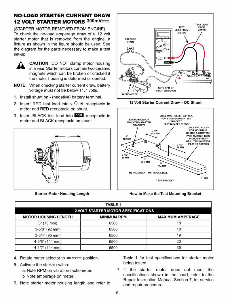
NO‑LOAD STARTER CURRENT DRAW 12 VOLT STARTER MOTORS 300mV
(STARTER MOTOR REMOVED fROM ENGINE)To check the no‑load amperage draw of a 12 volt starter motor that is removed from the engine, a fixture as shown in the figure should be used. See the diagram for the parts necessary to make a test set‑up.
CAUTION: DO NOT clamp motor housing in a vise. Starter motors contain two ceramic magnets which can be broken or cracked if the motor housing is deformed or dented.
NOTE: When checking starter current draw, battery voltage must not be below 11.7 volts.
1. Install shunt on - (negative) battery terminal.
2. Insert RED test lead into v receptacle in meter and RED receptacle on shunt.
3. Insert BLACK test lead into COM receptacle in meter and BLACK receptacle on shunt.
How to Make the Test Mounting BracketStarter Motor Housing Length
TABLE 1
12 VOLT STARTER MOTOR SPECIFICATIONS
MOTOR HOUSING LENGTH MINIMUM RPM MAXIMUM AMPERAGE
3" (76 mm) 6500 18
3‑5/8" (92 mm) 6500 18
3‑3/4" (95 mm) 6500 19
4‑3/8" (111 mm) 6500 20
4‑1/2" (114 mm) 6500 35
4. Rotate meter selector to 300mV position.
5. Activate the starter switch:a. Note RPM on vibration tachometer.b. Note amperage on meter.
6. Note starter motor housing length and refer to
Table 1 for test specifications for starter motor being tested.
7. If the starter motor does not meet the specifications shown in the chart, refer to the Repair Instruction Manual, Section 7, for service and repair procedure.
PRESS TO START
“L”
TACHOMETER
NOTE RPM OF STARTER MOTOR
TEST LEAD FROM
METER
TEST LEAD FROM
METER
EXTRA HOLE FOR MOUNTING STARTER
BRACKETS
DRILL TWO HOLES – 3/8" DIA. FOR STARTER MOUNTING
BRACKET PART NUMBER 392749
DRILL TWO HOLES FOR MOUNTING
BRIGGS & STRATTON PART NUMBER 19200
TACHOMETER #7 DRILL TAP HOLE FOR
1/4-20 NC SCREWS
TEST BRACKET
METAL STOCK – 1/4" THICK STEEL2"
51 MM
3-1/2" 89 MM
2-1/4" 57.2 MM
4" 102 MM
3-1/2" 89 MM
1" 25.4 MM 10"
254 MM
12 Volt Starter Current Draw – DC Shunt
9
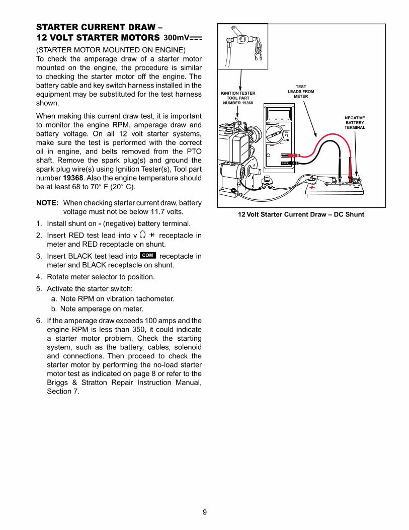
STARTER CURRENT DRAW – 12 VOLT STARTER MOTORS 300mV(STARTER MOTOR MOUNTED ON ENGINE)To check the amperage draw of a starter motor mounted on the engine, the procedure is similar to checking the starter motor off the engine. The battery cable and key switch harness installed in the equipment may be substituted for the test harness shown.
When making this current draw test, it is important to monitor the engine RPM, amperage draw and battery voltage. On all 12 volt starter systems, make sure the test is performed with the correct oil in engine, and belts removed from the PTO shaft. Remove the spark plug(s) and ground the spark plug wire(s) using Ignition Tester(s), Tool part number 19368. Also the engine temperature should be at least 68 to 70° f (20° C).
NOTE: When checking starter current draw, battery voltage must not be below 11.7 volts.
1. Install shunt on - (negative) battery terminal.
2. Insert RED test lead into v receptacle in meter and RED receptacle on shunt.
3. Insert BLACK test lead into COM receptacle in meter and BLACK receptacle on shunt.
4. Rotate meter selector to position.
5. Activate the starter switch:a. Note RPM on vibration tachometer.b. Note amperage on meter.
6. If the amperage draw exceeds 100 amps and the engine RPM is less than 350, it could indicate a starter motor problem. Check the starting system, such as the battery, cables, solenoid and connections. Then proceed to check the starter motor by performing the no‑load starter motor test as indicated on page 8 or refer to the Briggs & Stratton Repair Instruction Manual, Section 7.
12 Volt Starter Current Draw – DC Shunt
TEST LEADS FROM
METERIGNITION TESTER
TOOL PART NUMBER 19368
NEGATIVE BATTERY
TERMINAL
10
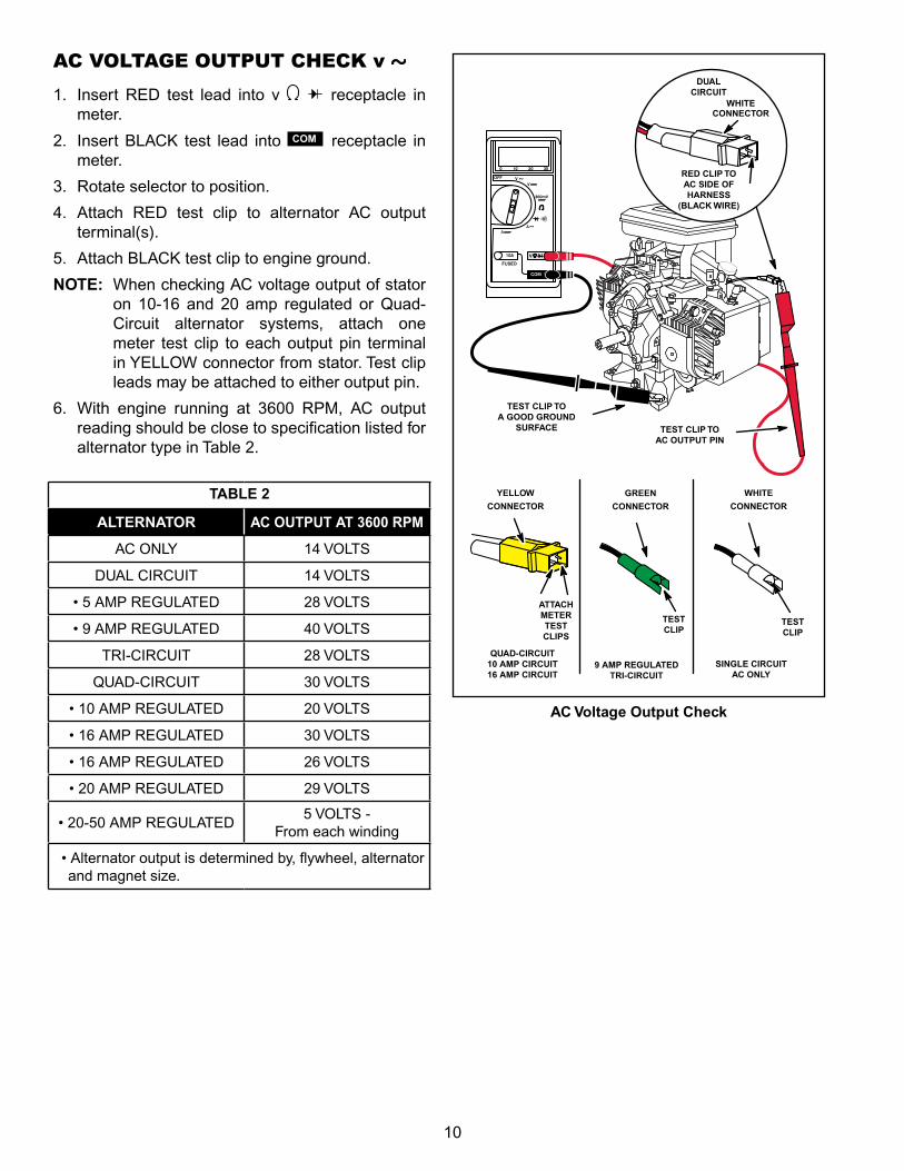
AC VOLTAGE OUTPUT CHECK v
1. Insert RED test lead into v receptacle in meter.
2. Insert BLACK test lead into COM receptacle in meter.
3. Rotate selector to position.
4. Attach RED test clip to alternator AC output terminal(s).
5. Attach BLACK test clip to engine ground.
NOTE: When checking AC voltage output of stator on 10‑16 and 20 amp regulated or Quad‑Circuit alternator systems, attach one meter test clip to each output pin terminal in YELLOW connector from stator. Test clip leads may be attached to either output pin.
6. With engine running at 3600 RPM, AC output reading should be close to specification listed for alternator type in Table 2.
AC Voltage Output Check
TABLE 2
ALTERNATOR AC OUTPUT AT 3600 RPM
AC ONLY 14 VOLTS
DUAL CIRCUIT 14 VOLTS
• 5 AMP REGULATED 28 VOLTS
• 9 AMP REGULATED 40 VOLTS
TRI‑CIRCUIT 28 VOLTS
QUAD‑CIRCUIT 30 VOLTS
• 10 AMP REGULATED 20 VOLTS
• 16 AMP REGULATED 30 VOLTS
• 16 AMP REGULATED 26 VOLTS
• 20 AMP REGULATED 29 VOLTS
• 20-50 AMP REGULATED5 VOLTS ‑
from each winding
• Alternator output is determined by, flywheel, alternator and magnet size.
WHITECONNECTOR
DUAL CIRCUIT
RED CLIP TO AC SIDE OF HARNESS
(BLACK WIRE)
TEST CLIP TO AC OUTPUT PIN
TEST CLIP TO A GOOD GROUND
SURFACE
WHITE
CONNECTOR
TEST CLIP
GREEN
CONNECTOR
YELLOW
CONNECTOR
TEST CLIP
ATTACH METER TEST CLIPS
QUAD-CIRCUIT 10 AMP CIRCUIT 16 AMP CIRCUIT
9 AMP REGULATED TRI-CIRCUIT
SINGLE CIRCUIT AC ONLY
11
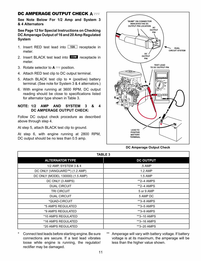
DC AMPERAGE OUTPUT CHECK See Note Below For 1/2 Amp and System 3 & 4 Alternators
See Page 12 for Special Instructions on Checking DC Amperage Output of 16 and 20 Amp Regulated System
1. Insert RED test lead into receptacle in meter.
2. Insert BLACK test lead into COM receptacle in meter.
3. Rotate selector to position.
4. Attach RED test clip to DC output terminal.
5. Attach BLACK test clip to + (positive) battery terminal. (See note for System 3 & 4 alternators.)
6. With engine running at 3600 RPM, DC output reading should be close to specifications listed for alternator type shown in Table 3.
NOTE: 1/2 AMP AND SYSTEM 3 & 4 DC AMPERAGE OUTPUT CHECK:
follow DC output check procedure as described above through step 4.
At step 5, attach BLACK test clip to ground.
At step 6, with engine running at 2800 RPM, DC output should be no less than 0.5 amp.
DC Amperage Output Check
* Connect test leads before starting engine. Be sure connections are secure. If a test lead vibrates loose while engine is running, the regulator/ rectifier may be damaged.
** Amperage will vary with battery voltage. If battery voltage is at its maximum, the amperage will be less than the higher value shown.
TABLE 3
ALTERNATOR TYPE DC OUTPUT
1/2 AMP, SYSTEM 3 & 4 .5 AMP
DC ONLY (VANGUARD™) (1.2 AMP) 1.2 AMP
DC ONLY (MODEL 130000) (1.5 AMP) 1.5 AMP
DC ONLY (3 AMPS) **2–4 AMPS
DUAL CIRCUIT **2–4 AMPS
TRI CIRCUIT 5 or 9 AMP
DUAL CIRCUIT 5 AMP DC
*QUAD‑CIRCUIT **3–8 AMPS
*5 AMPS REGULATED **3–5 AMPS
*9 AMPS REGULATED **3–9 AMPS
*10 AMPS REGULATED **3–10 AMPS
*16 AMPS REGULATED **3–16 AMPS
*20 AMPS REGULATED **3–20 AMPS
TEST LEAD TO DC OUTPUT PIN
“BUMP” ON CONNECTOR INDICATES THE DC
OUTPUT PIN LOCATION
LEAD TO POSITIVE BATTERY
TERMINAL
AC OUTPUT
PIN
DC OUTPUT
PIN
DUAL CIRCUIT SYSTEM
12
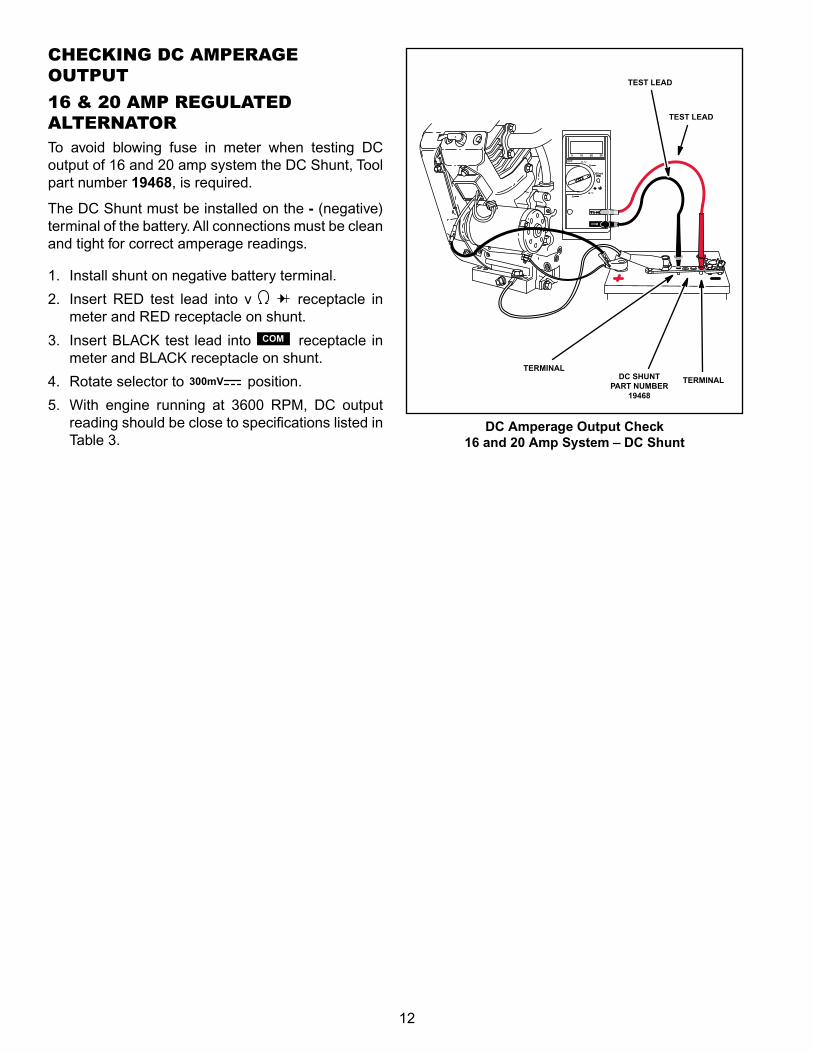
CHECKING DC AMPERAGE OUTPUT
16 & 20 AMP REGULATED ALTERNATORTo avoid blowing fuse in meter when testing DC output of 16 and 20 amp system the DC Shunt, Tool part number 19468, is required.
The DC Shunt must be installed on the - (negative) terminal of the battery. All connections must be clean and tight for correct amperage readings.
1. Install shunt on negative battery terminal.
2. Insert RED test lead into v receptacle in meter and RED receptacle on shunt.
3. Insert BLACK test lead into COM receptacle in meter and BLACK receptacle on shunt.
4. Rotate selector to 300mV position.
5. With engine running at 3600 RPM, DC output reading should be close to specifications listed in Table 3.
DC Amperage Output Check16 and 20 Amp System – DC Shunt
TEST LEAD
DC SHUNT PART NUMBER
19468
TEST LEAD
TERMINAL
TERMINAL
13
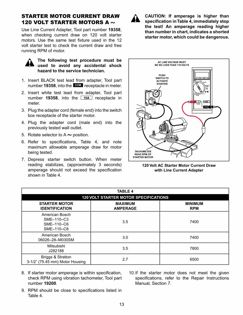
STARTER MOTOR CURRENT DRAW 120 VOLT STARTER MOTORS A Use Line Current Adapter, Tool part number 19358, when checking current draw on 120 volt starter motors. Use the same test fixture used in the 12 volt starter test to check the current draw and free running RPM of motor.
The following test procedure must be used to avoid any accidental shock hazard to the service technician.
1. Insert BLACK test lead from adapter, Tool part number 19358, into the COM receptacle in meter.
2. Insert white test lead from adapter, Tool part number 19358, into the receptacle in meter.
3. Plug the adapter cord (female end) into the switch box receptacle of the starter motor.
4. Plug the adapter cord (male end) into the previously tested wall outlet.
5. Rotate selector to A position.
6. Refer to specifications, Table 4, and note maximum allowable amperage draw for motor being tested.
7. Depress starter switch button. When meter reading stabilizes, (approximately 3 seconds) amperage should not exceed the specification shown in Table 4.
CAUTION: If amperage is higher than specification in Table 4, immediately stop the test! An amperage reading higher than number in chart, indicates a shorted starter motor, which could be dangerous.
120 Volt AC Starter Motor Current Draw with Line Current Adapter
8. If starter motor amperage is within specification, check RPM using vibration tachometer, Tool part number 19200.
9. RPM should be close to specifications listed in Table 4.
10. If the starter motor does not meet the given specifications, refer to the Repair Instructions Manual, Section 7.
TABLE 4
120 VOLT STARTER MOTOR SPECIFICATIONS
STARTER MOTOR IDENTIFICATION
MAXIMUM AMPERAGE
MINIMUM RPM
American Bosch SME–110–C3 SME–110–C6 SME–110–C8
3.5 7400
American Bosch 06026–28–M030SM
3.0 7400
Mitsubishi J282188
3.5 7800
Briggs & Stratton 3‑1/2˝ (75.45 mm) Motor Housing
2.7 6500
PUSH SWITCH TO ACTIVATE STARTER
TACHOMETER READ RPM OF
STARTER MOTOR
AC LINE VOLTAGE MUST BE NO LESS THAN 110 VOLTS
14
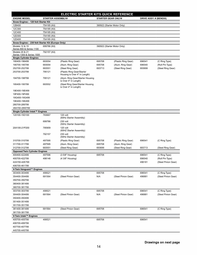
ELECTRIC STARTER KITS QUICK REFERENCEENGINE MODEL STARTER ASSEMBLY# STARTER GEAR ONLY# DRIVE ASSY. # (BENDIX)
Snow Engines ‑ 120 Volt Starter Kit
12B400 754185 (Kit) 390922 (Starter Motor Only)
12C300 754185 (Kit)
12C400 754185 (Kit)
12D300 754185 (Kit)
12D400 754185 (Kit)
Snow Engines ‑ 230 Volt Starter Kit (Europe Only)
Models 12 & 15Series 800 & Series 1100
699786 (Kit) 390922 (Starter Motor Only)
Models 20 & 21Series 1300 & Series 1500
792157 (Kit)
Single Cylinder Engines
190400‑196499 693054 (Plastic Ring Gear) 695708 (Plastic Ring Gear) 696541 (C Ring Type)
190700‑195799 693054 (Alum. Ring Gear) 695708 (Alum. Ring Gear) 696540 (Roll Pin Type)
252700‑252799 693551 (Steel Ring Gear) 693713 (Steel Ring Gear) 693699 (Steel Ring Gear)
253700‑253799 795121 (Plastic Ring Gear/Starter Housing is Over 4" in Length)
194700‑198799 795121 (Alum. Ring Gear/Starter Housing is Over 4" in Length)
195400‑195799 693552 (Steel Ring Gear/Starter Housing is Over 4" in Length)
19E400‑19E499
19f400‑19f499
19G400‑19G499
19K400‑19K499
280700‑289799
28A700‑28W799
Single Cylinder Intek™ Engines
120100‑15D100 793667 120 volt (60Hz Starter Assembly)
699786 230 volt (50Hz Starter Assembly)
20A100‑21P200 795909 120 volt (60HZ Starter Assembly)
792157 230 volt (50Hz Starter Assembly)
310700‑310799 497595 (Plastic Ring Gear) 695708 (Plastic Ring Gear) 696541 (C Ring Type)
311700‑311799 497595 (Alum. Ring Gear) 695708 (Alum. Ring Gear)
312700‑312799 693551 (Steel Ring Gear) 693699 (Steel Ring Gear) 693713 (Steel Ring Gear)
Opposed Twin Cylinder Engines
400400‑422499 497596 (3 5/8" Housing) 695708 696541 (C Ring Type)
400700‑422799 498148 (4 3/8" Housing) 696540 (Roll Pin Type)
42A700‑42E799 496181 (Steel Pinion Gear)
406700‑461799
V-Twin Vanguard™ Engines
303400‑303499 499521 695708 696541 (C Ring Type)
354400‑354499 691564 (Steel Pinion Gear) N/A (Steel Pinion Gear) 496881 (Steel Pinion Gear)
350700‑350799
380400‑381499
380700‑381799
303700‑303799 499521 695708 696541 (C Ring Type)
304400‑304499 691564 (Steel Pinion Gear) N/A (Steel Pinion Gear) 496881 (Steel Pinion Gear)
350400‑350499
351400‑351499
351700‑351799
381400‑381499 691564 (Steel Pinion Gear) 695708 696541 (C Ring Type)
381700‑381799
V-Twin Intek™ Engines
405700‑405799 499521 695708 696541
406700‑406799
407700‑407799
445700‑445799
Drawings on next page
15
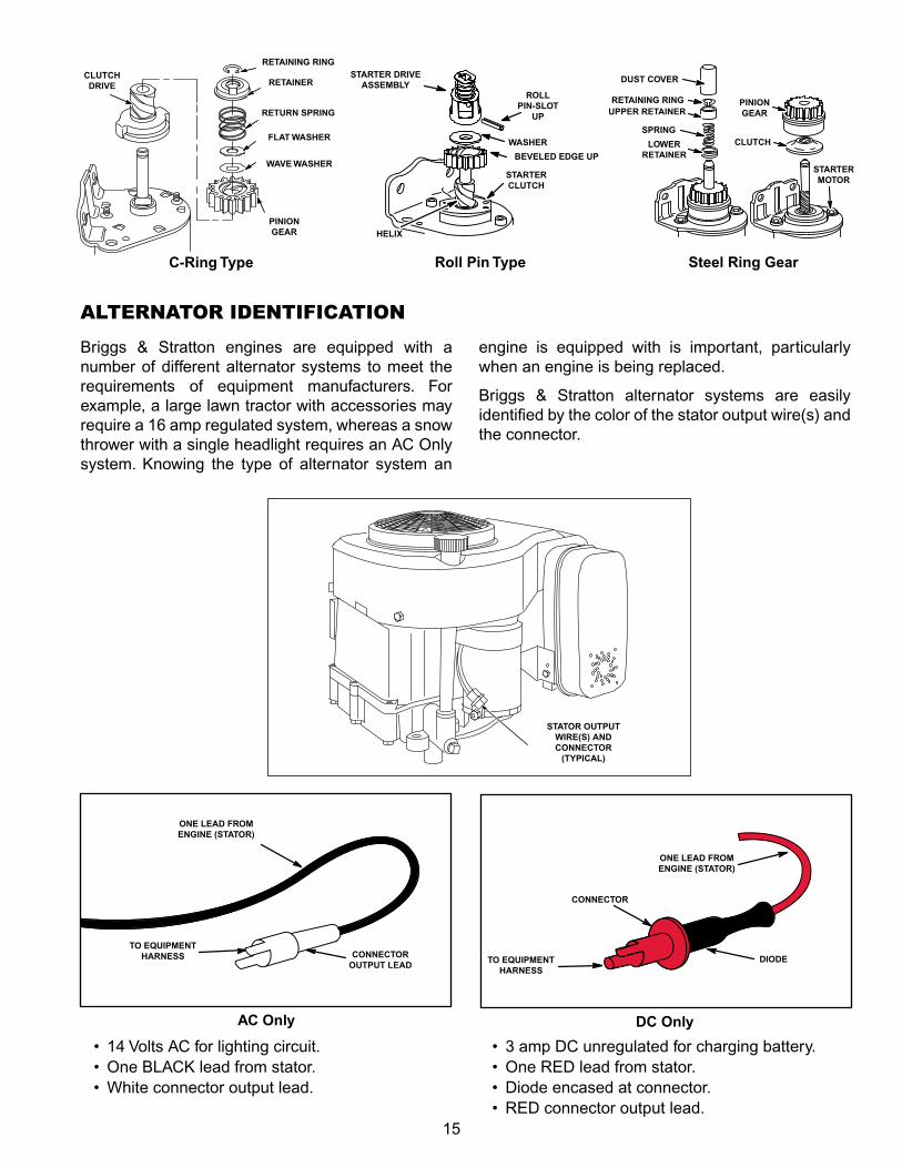
Briggs & Stratton engines are equipped with a number of different alternator systems to meet the requirements of equipment manufacturers. for example, a large lawn tractor with accessories may require a 16 amp regulated system, whereas a snow thrower with a single headlight requires an AC Only system. Knowing the type of alternator system an
engine is equipped with is important, particularly when an engine is being replaced.
Briggs & Stratton alternator systems are easily identified by the color of the stator output wire(s) and the connector.
DC OnlyAC Only
STATOR OUTPUT WIRE(S) AND CONNECTOR
(TYPICAL)
ALTERNATOR IDENTIFICATION
• 14 Volts AC for lighting circuit.• One BLACK lead from stator.• White connector output lead.
• 3 amp DC unregulated for charging battery.• One RED lead from stator.• Diode encased at connector.• RED connector output lead.
ONE LEAD FROM ENGINE (STATOR)
TO EQUIPMENT HARNESS CONNECTOR
OUTPUT LEAD
ONE LEAD FROM ENGINE (STATOR)
TO EQUIPMENT HARNESS
CONNECTOR
DIODE
C-Ring Type Roll Pin Type Steel Ring Gear
CLUTCH DRIVE RETAINER
RETURN SPRING
PINION GEAR
BEVELED EDGE UP
STARTER CLUTCH
WASHER
ROLL PIN-SLOT
UP
STARTER DRIVE ASSEMBLY
HELIX
PINION GEAR
DUST COVER
RETAINING RINGUPPER RETAINER
SPRINGCLUTCHLOWER
RETAINER
STARTER MOTOR
RETAINING RING
FLAT WASHER
WAVE WASHER
16
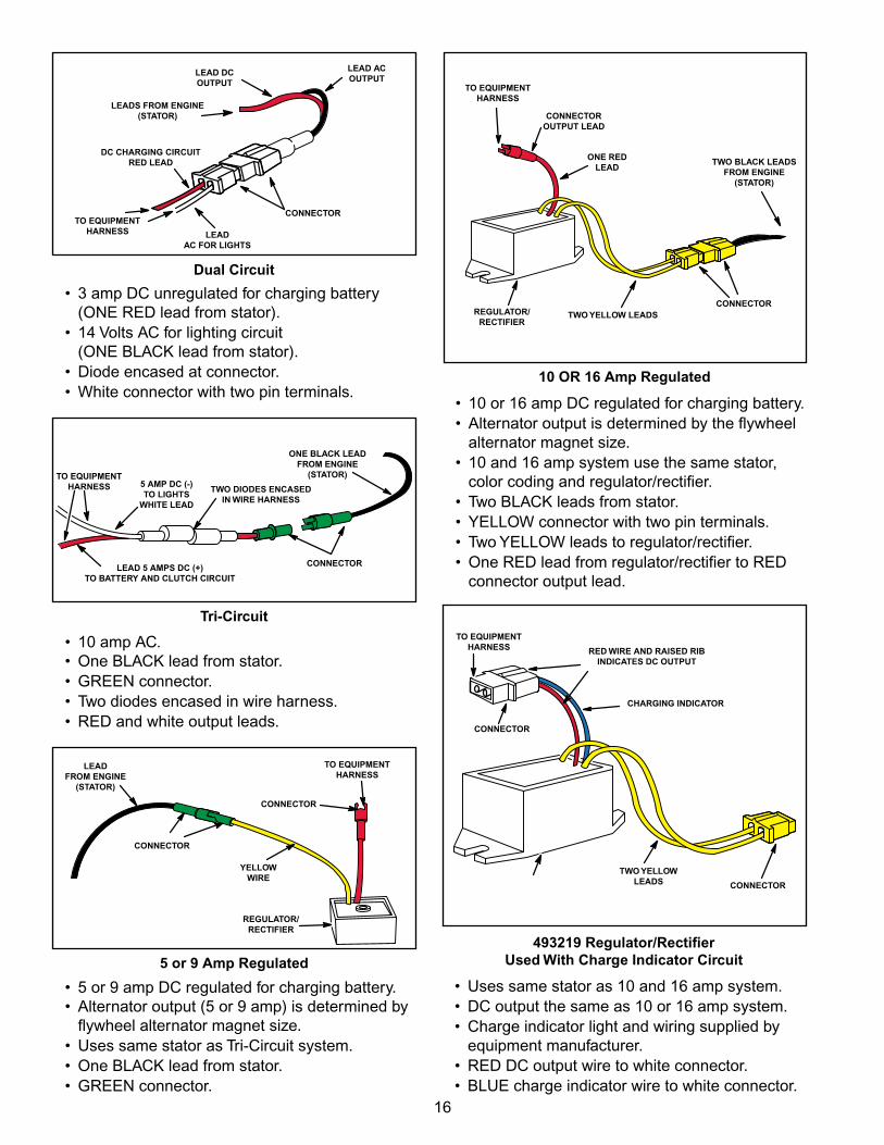
• 3 amp DC unregulated for charging battery (ONE RED lead from stator).• 14 Volts AC for lighting circuit (ONE BLACK lead from stator).• Diode encased at connector.• White connector with two pin terminals.
LEADS FROM ENGINE (STATOR)
TO EQUIPMENT HARNESS
Tri-Circuit
Dual Circuit
LEAD DC OUTPUT
LEAD AC OUTPUT
LEAD AC FOR LIGHTS
CONNECTOR
DC CHARGING CIRCUIT RED LEAD
• 10 amp AC. • One BLACK lead from stator.• GREEN connector.• Two diodes encased in wire harness.• RED and white output leads.
• 5 or 9 amp DC regulated for charging battery. • Alternator output (5 or 9 amp) is determined by flywheel alternator magnet size.• Uses same stator as Tri-Circuit system.• One BLACK lead from stator.• GREEN connector.
5 or 9 Amp Regulated
TO EQUIPMENT HARNESS 5 AMP DC (-)
TO LIGHTS WHITE LEAD
TWO DIODES ENCASED IN WIRE HARNESS
ONE BLACK LEAD FROM ENGINE
(STATOR)
CONNECTORLEAD 5 AMPS DC (+) TO BATTERY AND CLUTCH CIRCUIT
CONNECTOR
TO EQUIPMENT HARNESS
LEAD FROM ENGINE
(STATOR)
CONNECTOR
YELLOW WIRE
REGULATOR/ RECTIFIER
• 10 or 16 amp DC regulated for charging battery.• Alternator output is determined by the flywheel alternator magnet size.• 10 and 16 amp system use the same stator, color coding and regulator/rectifier.• Two BLACK leads from stator.• YELLOW connector with two pin terminals.• Two YELLOW leads to regulator/rectifier.• One RED lead from regulator/rectifier to RED connector output lead.
10 OR 16 Amp Regulated
REGULATOR/ RECTIFIER
TO EQUIPMENT HARNESS
CONNECTORTWO YELLOW LEADS
ONE RED LEAD
TWO BLACK LEADS FROM ENGINE
(STATOR)
CONNECTOR OUTPUT LEAD
• Uses same stator as 10 and 16 amp system.• DC output the same as 10 or 16 amp system.• Charge indicator light and wiring supplied by equipment manufacturer.• RED DC output wire to white connector.• BLUE charge indicator wire to white connector.
493219 Regulator/Rectifier Used With Charge Indicator Circuit
TO EQUIPMENT HARNESS
TWO YELLOW LEADS CONNECTOR
CONNECTOR
RED WIRE AND RAISED RIB INDICATES DC OUTPUT
CHARGING INDICATOR
17
ENGINE/ALTERNATOR REPLACEMENT INFORMATIONWith the exception of the AC Only alternator, all of the alternator systems referred to in this book have a battery as part of the electrical system.
There are specialized applications that use an alternator without a battery. An example would be certain generators or welders that use alternator output to excite an electrical field. for the equipment to function, the alternator output must be very evenly matched to the equipment requirements. When replacing an engine in these applications, the alternator must be the same as the original.
REPLACING BRIGGS & STRATTON® ENGINESWhen replacing an older Briggs & Stratton engine on a piece of equipment with a newer Briggs & Stratton engine, sometimes the newer engine has an alternator system different from the alternator system on the original engine. This means that the output connector on the replacement engine is not compatible with the original wiring harness on the piece of equipment. for example, the original engine may have been equipped with a Dual Circuit system and the replacement engine is equipped with a regulated system. We can integrate the two systems by making an adapter harness from readily available parts.
Generally an unregulated DC system (DC Only, Dual Circuit) should not be used to replace a regulated system because alternator output may not be sufficient for equipment requirements. However, because the equipment requirements are usually much less on an unregulated DC system, a regulated system may be used as a replacement. The regulator/rectifier prevents the battery from being over charged.
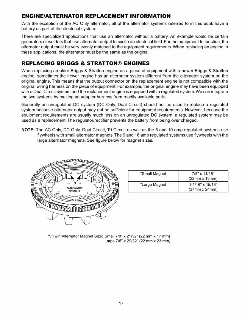
NOTE: The AC Only, DC Only, Dual Circuit, Tri‑Circuit as well as the 5 and 10 amp regulated systems use flywheels with small alternator magnets. The 9 and 16 amp regulated systems use flywheels with the large alternator magnets. See figure below for magnet sizes.
ALTERNATOR MAGNETS
*Small Magnet 7/8" x 11/16" (22mm x 18mm)
*Large Magnet 1‑1/16" x 15/16" (27mm x 24mm)
*V Twin Alternator Magnet Size: Small 7/8" x 21/32" (22 mm x 17 mm) Large 7/8" x 29/32" (22 mm x 23 mm)
18
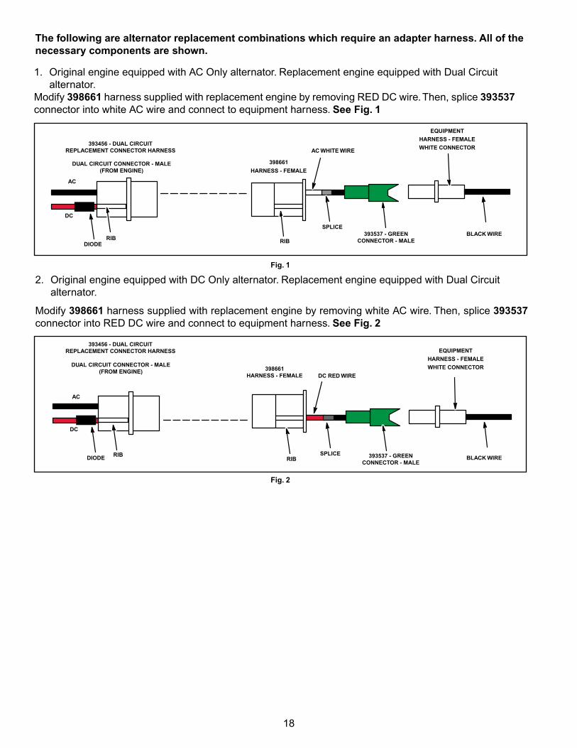
The following are alternator replacement combinations which require an adapter harness. All of the necessary components are shown.
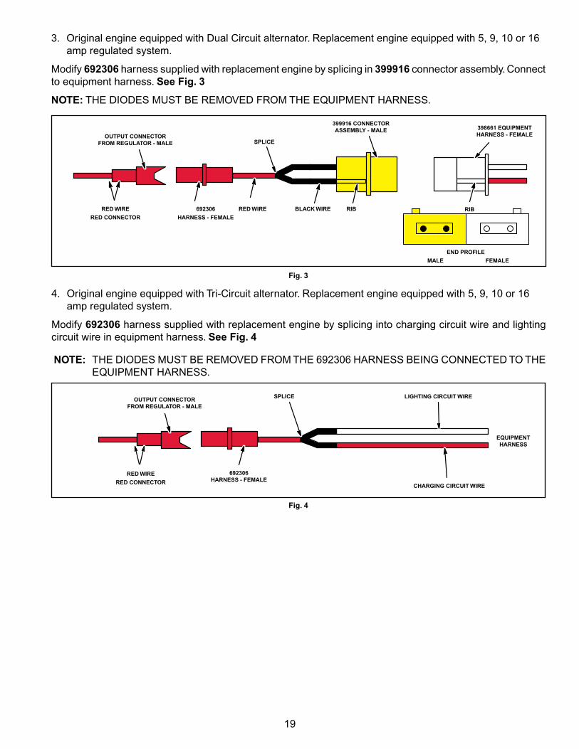
2. Original engine equipped with DC Only alternator. Replacement engine equipped with Dual Circuit alternator.
Modify 398661 harness supplied with replacement engine by removing white AC wire. Then, splice 393537 connector into RED DC wire and connect to equipment harness. See Fig. 2
EQUIPMENTHARNESS - FEMALEWHITE CONNECTOR
393456 - DUAL CIRCUIT REPLACEMENT CONNECTOR HARNESS
BLACK WIRE
DC RED WIRE398661
HARNESS - FEMALE
DUAL CIRCUIT CONNECTOR - MALE (FROM ENGINE)
AC
DC
RIBRIB
SPLICE 393537 - GREEN CONNECTOR - MALE
DIODE
EQUIPMENTHARNESS - FEMALEWHITE CONNECTORAC WHITE WIRE
398661
HARNESS - FEMALEDUAL CIRCUIT CONNECTOR - MALE
(FROM ENGINE)
393456 - DUAL CIRCUIT REPLACEMENT CONNECTOR HARNESS
AC
DC
RIB RIB
SPLICE393537 - GREEN
CONNECTOR - MALEBLACK WIRE
DIODE
Fig. 1
Fig. 2
1. Original engine equipped with AC Only alternator. Replacement engine equipped with Dual Circuit alternator.
Modify 398661 harness supplied with replacement engine by removing RED DC wire. Then, splice 393537 connector into white AC wire and connect to equipment harness. See Fig. 1
19
4. Original engine equipped with Tri‑Circuit alternator. Replacement engine equipped with 5, 9, 10 or 16 amp regulated system.
Modify 692306 harness supplied with replacement engine by splicing into charging circuit wire and lighting circuit wire in equipment harness. See Fig. 4
NOTE: THE DIODES MUST BE REMOVED fROM THE 692306 HARNESS BEING CONNECTED TO THE EQUIPMENT HARNESS.
RED WIRE
RED CONNECTOR
EQUIPMENT HARNESS
692306 HARNESS - FEMALE
SPLICEOUTPUT CONNECTOR FROM REGULATOR - MALE
LIGHTING CIRCUIT WIRE
CHARGING CIRCUIT WIRE
Fig. 4
3. Original engine equipped with Dual Circuit alternator. Replacement engine equipped with 5, 9, 10 or 16 amp regulated system.
Modify 692306 harness supplied with replacement engine by splicing in 399916 connector assembly. Connect to equipment harness. See Fig. 3
NOTE: THE DIODES MUST BE REMOVED fROM THE EQUIPMENT HARNESS.
398661 EQUIPMENT HARNESS - FEMALE
RIB RIB
END PROFILE
MALE FEMALE
692306
HARNESS - FEMALE
RED WIRE
RED CONNECTOR
RED WIRE BLACK WIRE
SPLICEOUTPUT CONNECTOR
FROM REGULATOR - MALE
399916 CONNECTOR ASSEMBLY - MALE
Fig. 3
20
Fig. 5
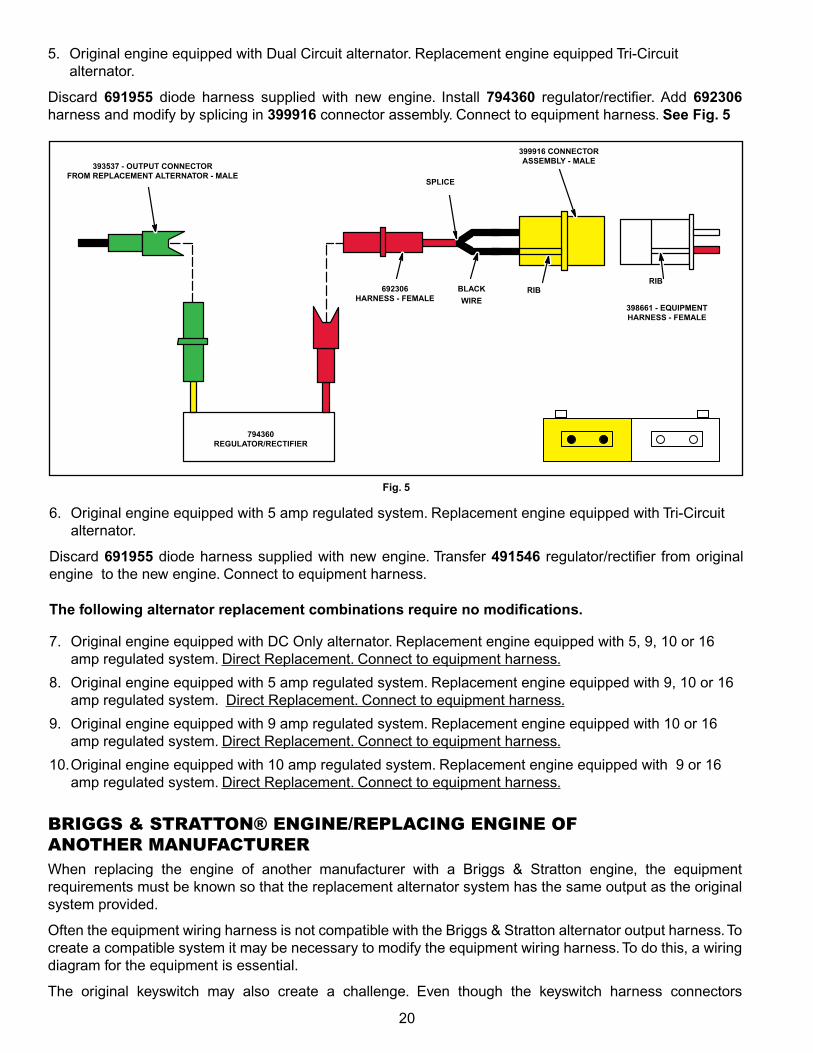
5. Original engine equipped with Dual Circuit alternator. Replacement engine equipped Tri‑Circuit alternator.
Discard 691955 diode harness supplied with new engine. Install 794360 regulator/rectifier. Add 692306 harness and modify by splicing in 399916 connector assembly. Connect to equipment harness. See Fig. 5
398661 - EQUIPMENT HARNESS - FEMALE
RIBRIB
692306 HARNESS - FEMALE
BLACK
WIRE
SPLICE
393537 - OUTPUT CONNECTOR FROM REPLACEMENT ALTERNATOR - MALE
399916 CONNECTOR ASSEMBLY - MALE
794360 REGULATOR/RECTIFIER
6. Original engine equipped with 5 amp regulated system. Replacement engine equipped with Tri‑Circuit alternator.
Discard 691955 diode harness supplied with new engine. Transfer 491546 regulator/rectifier from original engine to the new engine. Connect to equipment harness.
The following alternator replacement combinations require no modifications.
7. Original engine equipped with DC Only alternator. Replacement engine equipped with 5, 9, 10 or 16 amp regulated system. Direct Replacement. Connect to equipment harness.
8. Original engine equipped with 5 amp regulated system. Replacement engine equipped with 9, 10 or 16 amp regulated system. Direct Replacement. Connect to equipment harness.
9. Original engine equipped with 9 amp regulated system. Replacement engine equipped with 10 or 16 amp regulated system. Direct Replacement. Connect to equipment harness.
10. Original engine equipped with 10 amp regulated system. Replacement engine equipped with 9 or 16 amp regulated system. Direct Replacement. Connect to equipment harness.
BRIGGS & STRATTON® ENGINE/REPLACING ENGINE OF ANOTHER MANUFACTURERWhen replacing the engine of another manufacturer with a Briggs & Stratton engine, the equipment requirements must be known so that the replacement alternator system has the same output as the original system provided.
Often the equipment wiring harness is not compatible with the Briggs & Stratton alternator output harness. To create a compatible system it may be necessary to modify the equipment wiring harness. To do this, a wiring diagram for the equipment is essential.
The original keyswitch may also create a challenge. Even though the keyswitch harness connectors
21
appear to be identical, there are internal differences to keyswitches. Therefore it is necessary to have a diagram of the keyswitch showing the terminal positions and their functions. for example, see the 5 terminal switch diagrams in figure 1 and figure 2. The keyswitch in figure 1 is compatible with all Briggs & Stratton alternators. Note in figure 2, that when the “brand X” keyswitch is in the START position there is no battery voltage available to the #2 switch terminal. Consequently, if the replacement Briggs & Stratton engine was equipped with a carburetor solenoid, it would not function. This is why it is important to have a diagram of the keyswitch when replacing engines, or replace the keyswitch with one that is compatible with all Briggs & Stratton alternator systems.
It is not possible to show all of the wiring diagrams or keyswitch combinations that are used by equipment manufacturers. However, the following wiring diagrams for the most popular Briggs & Stratton engines may be used as a guide when replacing an engine. The wiring diagrams show the type of keyswitch that is compatible with the alternator system shown.
6
54
32
1
L M
G A
A
1-6-3 2-5-6 2-4-5
S
6
54
32
1
L M
G A
A
S
6
54
32
1
L M
G A
A
S
OFF RUN START
Figure 8Part# 692318
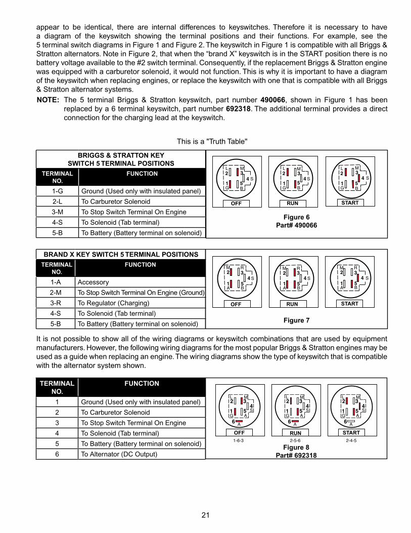
TERMINAL NO.
FUNCTION
1 Ground (Used only with insulated panel)
2 To Carburetor Solenoid
3 To Stop Switch Terminal On Engine
4 To Solenoid (Tab terminal)
5 To Battery (Battery terminal on solenoid)
6 To Alternator (DC Output)
NOTE: The 5 terminal Briggs & Stratton keyswitch, part number 490066, shown in figure 1 has been replaced by a 6 terminal keyswitch, part number 692318. The additional terminal provides a direct connection for the charging lead at the keyswitch.
This is a "Truth Table"
5
32
1
M
G
L
S
B5
32
1
M
G
L
S
B5
32
1
M
G
L
S
B
44 4
BRIGGS & STRATTON KEY SWITCH 5 TERMINAL POSITIONS
TERMINAL NO.
FUNCTION
1‑G Ground (Used only with insulated panel)
2‑L To Carburetor Solenoid
3‑M To Stop Switch Terminal On Engine
4‑S To Solenoid (Tab terminal)
5‑B To Battery (Battery terminal on solenoid)
OFF RUN START
Figure 6Part# 490066
OFF RUN START
BRAND X KEY SWITCH 5 TERMINAL POSITIONSTERMINAL
NO.FUNCTION
1‑A Accessory
2‑M To Stop Switch Terminal On Engine (Ground)
3‑R To Regulator (Charging)
4‑S To Solenoid (Tab terminal)
5‑B To Battery (Battery terminal on solenoid) Figure 7
5
32
1
M
A
R
S
B5
32
1
M
A
R
S
B5
32
1
M
A
R
S
B
4 4 4

22
5
432
1
+-
+
−
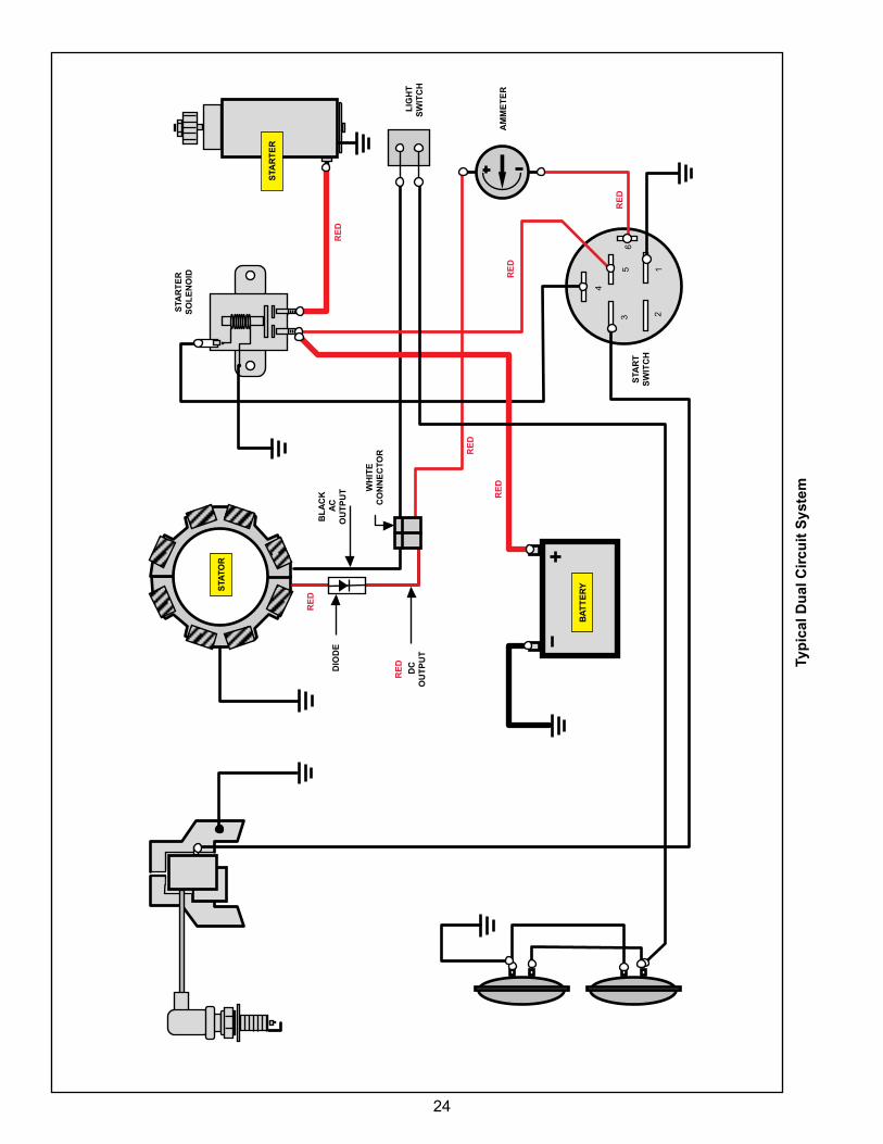
Typical Dual Circuit Alternator Wiring Diagram
Original 5-Pole Key Switch Part# 490066 Superceded to 6-Pole Key Switch, Briggs & Stratton Part# 692318
KEY SWITCH TEST
SWITCH POSITION CONTINUITY
1. Off *1 + 3
2. RUN 2 + 5
3. START 2 + 4 + 5
*Terminal 1 Grounded Internally To Key Switch Case
TERMINAL NO. FUNCTION
1 Ground (Used only with insulated panel)
2 To Carburetor Solenoid
3 To Stop Switch Terminal On Engine
4 To Solenoid (Tab terminal)
5 To Battery (Battery terminal on solenoid)
ALTERNATOR
KEY SWITCH
ANTI-AFTERFIRE SOLENOID
STOP SWITCH
TERMINAL
SOLENOID TAB TERMINAL
TO STARTER TERMINAL
SOLENOID
TO BATTERY TERMINAL
STARTER MOTOR
12 VOLT BATTERY
HEADLIGHTS
AMMETER
HEADLIGHT SWITCH
AC OUTPUT WIRE DC OUTPUT
WIRE
RED
DIODE
RED
RED
RED
RED
RED
23
54
32
1
+-
6
+−
+ −
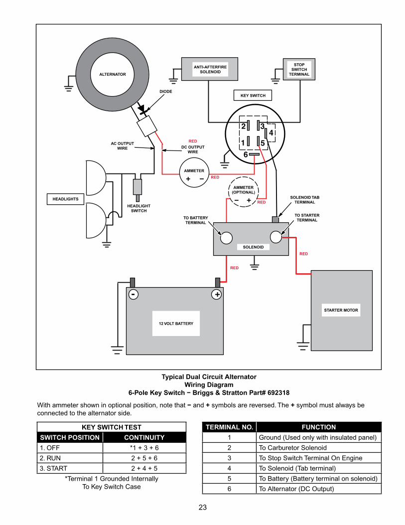
Typical Dual Circuit Alternator Wiring Diagram
6-Pole Key Switch − Briggs & Stratton Part# 692318
KEY SWITCH TEST
SWITCH POSITION CONTINUITY
1. Off *1 + 3 + 6
2. RUN 2 + 5 + 6
3. START 2 + 4 + 5
*Terminal 1 Grounded Internally To Key Switch Case
TERMINAL NO. FUNCTION
1 Ground (Used only with insulated panel)
2 To Carburetor Solenoid
3 To Stop Switch Terminal On Engine
4 To Solenoid (Tab terminal)
5 To Battery (Battery terminal on solenoid)
6 To Alternator (DC Output)
ALTERNATOR
KEY SWITCH
ANTI-AFTERFIRE SOLENOID
STOP SWITCH
TERMINAL
SOLENOID TAB TERMINAL
TO STARTER TERMINAL
SOLENOID
TO BATTERY TERMINAL
STARTER MOTOR
12 VOLT BATTERY
HEADLIGHTS
AMMETER
HEADLIGHT SWITCH
AC OUTPUT WIRE DC OUTPUT
WIRE
DIODE
AMMETER (OPTIONAL)
With ammeter shown in optional position, note that − and + symbols are reversed. The + symbol must always be connected to the alternator side.
RED
RED
RED
RED
RED
24
6
4
35
21
Typ
ical
Du
al C
ircu
it S
yste
m
STA
TOR
STA
RT
ER
S
OL
EN
OID
BA
TT
ER
Y
STA
RT
ER
BL
AC
K
AC
O
UT
PU
T WH
ITE
C
ON
NE
CTO
R
DIO
DE
RE
D
DC
O
UT
PU
T
AM
ME
TE
R
STA
RT
S
WIT
CH
L
IGH
T
SW
ITC
H
RE
D
RE
D
RE
D
RE
D
RE
D
RE
D
25
54
32
1
+-
+
−
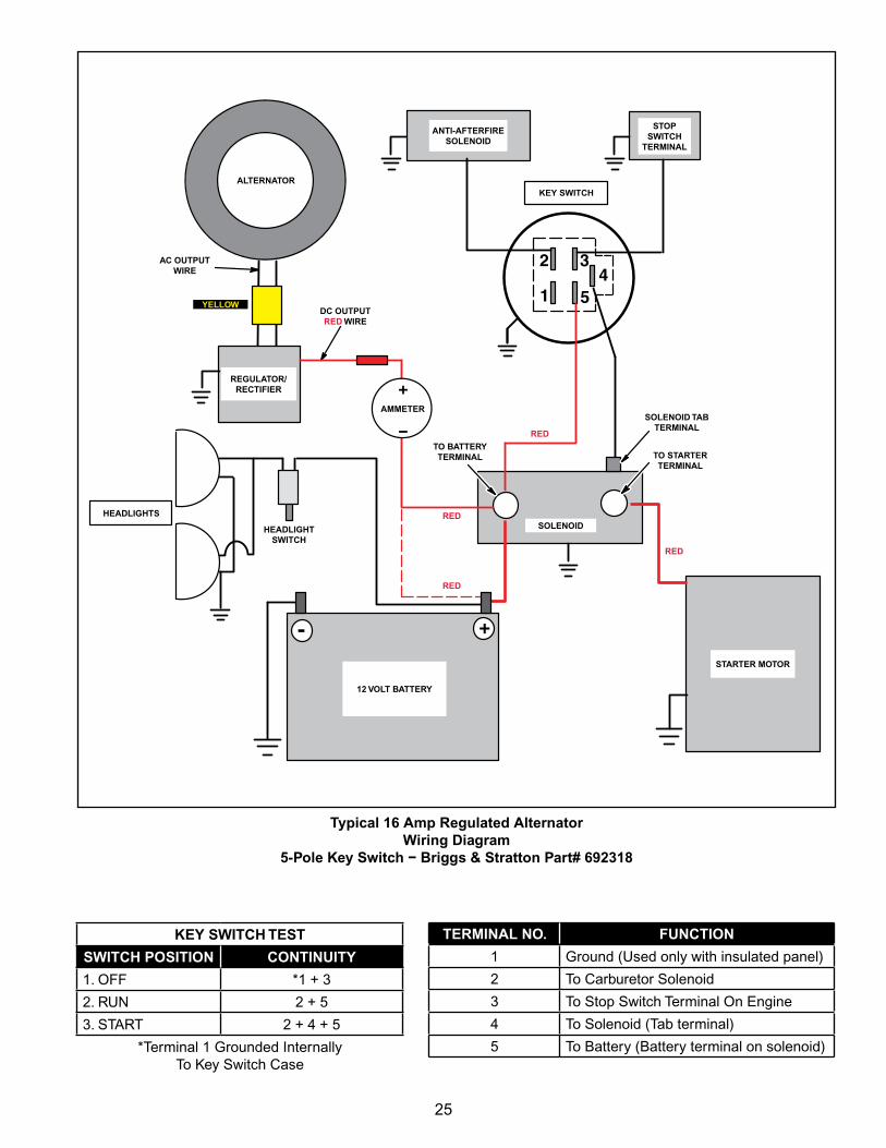
Typical 16 Amp Regulated AlternatorWiring Diagram
5-Pole Key Switch − Briggs & Stratton Part# 692318
KEY SWITCH TEST
SWITCH POSITION CONTINUITY
1. Off *1 + 3
2. RUN 2 + 5
3. START 2 + 4 + 5
*Terminal 1 Grounded Internally To Key Switch Case
TERMINAL NO. FUNCTION
1 Ground (Used only with insulated panel)
2 To Carburetor Solenoid
3 To Stop Switch Terminal On Engine
4 To Solenoid (Tab terminal)
5 To Battery (Battery terminal on solenoid)
ALTERNATORKEY SWITCH
ANTI-AFTERFIRE SOLENOID
STOP SWITCH
TERMINAL
SOLENOID TAB TERMINAL
TO STARTER TERMINAL
SOLENOID
TO BATTERY TERMINAL
STARTER MOTOR
12 VOLT BATTERY
HEADLIGHTS
AMMETER
HEADLIGHT SWITCH
AC OUTPUT WIRE
DC OUTPUT RED WIRE
REGULATOR/ RECTIFIER
YELLOW
RED
RED
RED
RED
26
-
65
432
1
+ −
+
+−
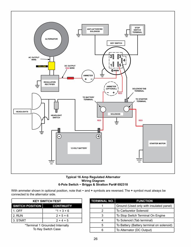
Typical 16 Amp Regulated AlternatorWiring Diagram
6-Pole Switch − Briggs & Stratton Part# 692318
KEY SWITCH TEST
SWITCH POSITION CONTINUITY
1. Off *1 + 3 + 6
2. RUN 2 + 5 + 6
3. START 2 + 4 + 5
*Terminal 1 Grounded Internally To Key Switch Case
TERMINAL NO. FUNCTION
1 Ground (Used only with insulated panel)
2 To Carburetor Solenoid
3 To Stop Switch Terminal On Engine
4 To Solenoid (Tab terminal)
5 To Battery (Battery terminal on solenoid)
6 To Alternator (DC Output)
ALTERNATOR
KEY SWITCH
ANTI-AFTERFIRE SOLENOID
STOP SWITCH
TERMINAL
SOLENOID TAB TERMINAL
TO STARTER TERMINAL
SOLENOID
TO BATTERY TERMINAL
STARTER MOTOR
12 VOLT BATTERY
HEADLIGHTS
AMMETER
HEADLIGHT SWITCH
AC OUTPUT WIRE
DC OUTPUT RED WIRE
REGULATOR/ RECTIFIER
AMMETER (OPTIONAL)
With ammeter shown in optional position, note that − and + symbols are reversed. The + symbol must always be connected to the alternator side.
YELLOW
RED
REDRED
27
-
65
432
1
+ −
+
+−
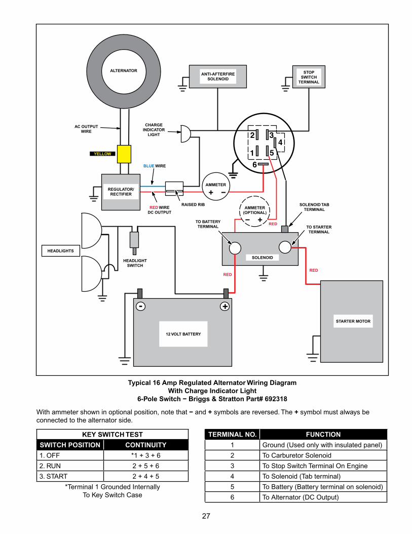
Typical 16 Amp Regulated Alternator Wiring DiagramWith Charge Indicator Light
6-Pole Switch − Briggs & Stratton Part# 692318
KEY SWITCH TEST
SWITCH POSITION CONTINUITY
1. Off *1 + 3 + 6
2. RUN 2 + 5 + 6
3. START 2 + 4 + 5
*Terminal 1 Grounded Internally To Key Switch Case
TERMINAL NO. FUNCTION
1 Ground (Used only with insulated panel)
2 To Carburetor Solenoid
3 To Stop Switch Terminal On Engine
4 To Solenoid (Tab terminal)
5 To Battery (Battery terminal on solenoid)
6 To Alternator (DC Output)
ALTERNATOR
BLUE WIRE
ANTI-AFTERFIRE SOLENOID
STOP SWITCH
TERMINAL
SOLENOID TAB TERMINAL
TO STARTER TERMINAL
SOLENOID
TO BATTERY TERMINAL
STARTER MOTOR
12 VOLT BATTERY
HEADLIGHTS
AMMETER
HEADLIGHT SWITCH
AC OUTPUT WIRE
CHARGE INDICATOR
LIGHT
REGULATOR/ RECTIFIER
AMMETER (OPTIONAL)
RED WIRE DC OUTPUT
RAISED RIB
With ammeter shown in optional position, note that − and + symbols are reversed. The + symbol must always be connected to the alternator side.
YELLOW
REDRED
RED
28
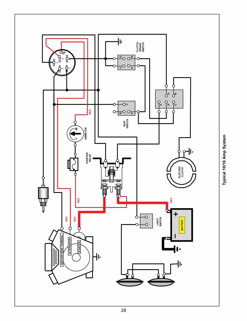
6
4
35
21
-+
Typ
ical
10/
16 A
mp
Sys
tem
STA
RT
ER
R
EL
AY
SE
AT
S
WIT
CH
GR
OU
ND
WIR
E T
ER
MIN
AL
ALT
ER
NA
TOR
STA
RT
ER
AM
ME
TE
R
CL
UT
CH
B
RA
KE
S
WIT
CH
D B
C A
C
B A
BA
CDEL
IGH
T
SW
ITC
H
EL
EC
TR
IC
CL
UT
CH
BA
TT
ER
YRE
D
RE
D
RE
D
RE
D
RE
D
29
+-
65
432
1
+ −
+−
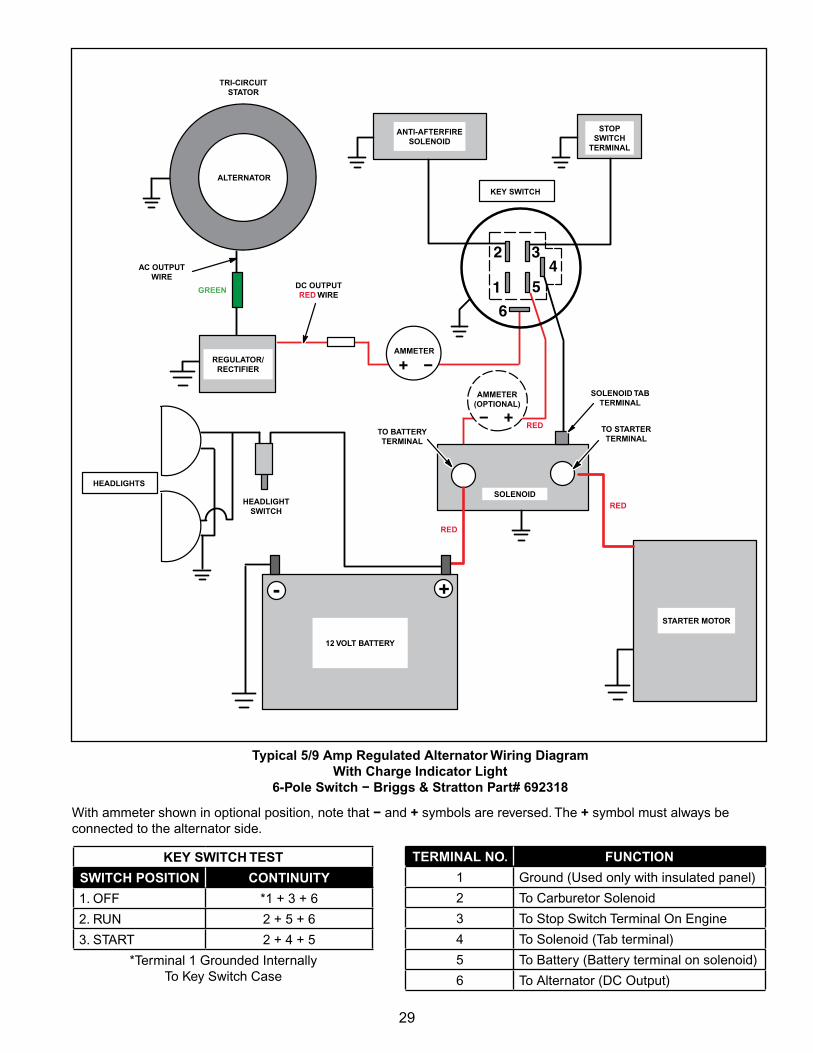
Typical 5/9 Amp Regulated Alternator Wiring DiagramWith Charge Indicator Light
6-Pole Switch − Briggs & Stratton Part# 692318
KEY SWITCH TEST
SWITCH POSITION CONTINUITY
1. Off *1 + 3 + 6
2. RUN 2 + 5 + 6
3. START 2 + 4 + 5
*Terminal 1 Grounded Internally To Key Switch Case
TERMINAL NO. FUNCTION
1 Ground (Used only with insulated panel)
2 To Carburetor Solenoid
3 To Stop Switch Terminal On Engine
4 To Solenoid (Tab terminal)
5 To Battery (Battery terminal on solenoid)
6 To Alternator (DC Output)
ALTERNATOR
KEY SWITCH
ANTI-AFTERFIRE SOLENOID
STOP SWITCH
TERMINAL
SOLENOID TAB TERMINAL
TO STARTER TERMINAL
SOLENOID
TO BATTERY TERMINAL
STARTER MOTOR
12 VOLT BATTERY
HEADLIGHTS
AMMETER
HEADLIGHT SWITCH
AC OUTPUT WIRE
TRI-CIRCUIT STATOR
REGULATOR/ RECTIFIER
AMMETER (OPTIONAL)
DC OUTPUT RED WIRE
With ammeter shown in optional position, note that − and + symbols are reversed. The + symbol must always be connected to the alternator side.
GREEN
RED
RED
RED
30
6
54
32
1
+ −
+-
+−
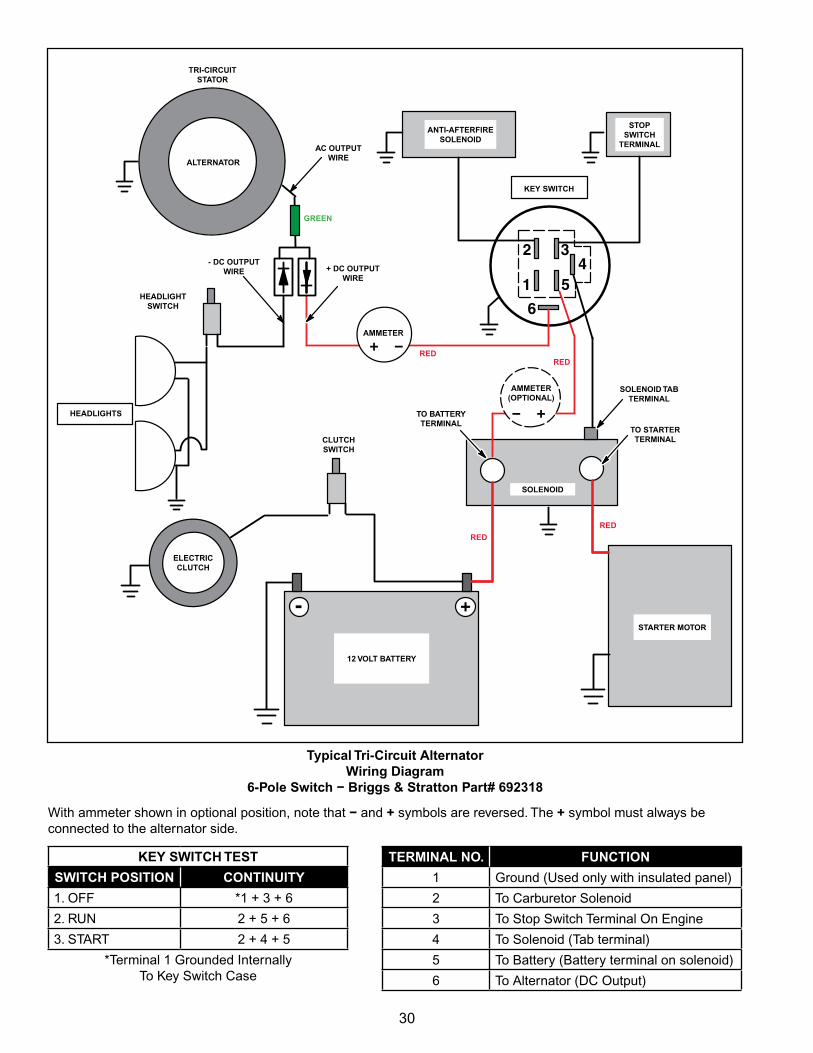
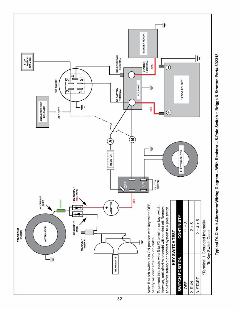
Typical Tri-Circuit Alternator Wiring Diagram
6-Pole Switch − Briggs & Stratton Part# 692318
KEY SWITCH TEST
SWITCH POSITION CONTINUITY
1. Off *1 + 3 + 6
2. RUN 2 + 5 + 6
3. START 2 + 4 + 5
*Terminal 1 Grounded Internally To Key Switch Case
TERMINAL NO. FUNCTION
1 Ground (Used only with insulated panel)
2 To Carburetor Solenoid
3 To Stop Switch Terminal On Engine
4 To Solenoid (Tab terminal)
5 To Battery (Battery terminal on solenoid)
6 To Alternator (DC Output)
ALTERNATOR
KEY SWITCH
ANTI-AFTERFIRE SOLENOID
STOP SWITCH
TERMINAL
SOLENOID TAB TERMINAL
TO STARTER TERMINAL
SOLENOID
TO BATTERY TERMINAL
STARTER MOTOR
12 VOLT BATTERY
HEADLIGHTS
AMMETER
ELECTRIC CLUTCH
AC OUTPUT WIRE
TRI-CIRCUIT STATOR
HEADLIGHT SWITCH
AMMETER (OPTIONAL)
+ DC OUTPUT WIRE
- DC OUTPUT WIRE
CLUTCH SWITCH
With ammeter shown in optional position, note that − and + symbols are reversed. The + symbol must always be connected to the alternator side.
GREEN
RED
RED
RED
RED
31
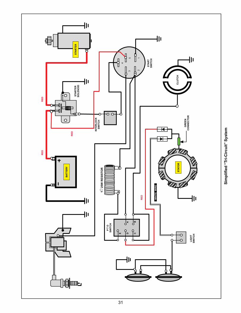
Sim
plifi
ed “
Tri-
Cir
cuit
” S
yste
m
4
35
21
BA
CDE
LIG
HT
S
WIT
CH
BA
TT
ER
Y
STA
TOR
STA
RT
ER
STA
RT
ER
S
OL
EN
OID
STA
RT
S
WIT
CH
INT
ER
LO
CK
S
WIT
CH
P T
O
SW
ITC
H
1 2
5W R
ES
ISTO
R
GR
EE
N
CO
NN
EC
TOR
CL
UT
CH
RE
DR
ED
RE
D
RE
D
WH
ITE
WIR
E
32
5
43
2
+
1
−
+ −
A B
ON
OF
F
Not
e: If
clu
tch
switc
h is
in O
N p
ositi
on w
ith k
eysw
itch
Of
f,
batte
ry w
ill d
isch
arge
thro
ugh
clut
ch.
To p
reve
nt th
is, r
oute
wire
B to
#2
term
inal
on
key‑
switc
h.
How
ever
, ant
i‑afte
rfire
sol
enoi
d w
ill n
ot s
hut o
ff. R
emov
e an
ti‑af
terfi
re s
olen
oid
or c
onve
rt s
yste
m to
6 p
ole
switc
h.
KE
Y S
WIT
CH
TE
ST
SW
ITC
H P
OS
ITIO
NC
ON
TIN
UIT
Y
1. O
ff
*1 +
3
2. R
UN
2 +
5
3. S
TAR
T2
+ 4
+ 5
*Ter
min
al 1
Gro
unde
d In
tern
ally
To
Key
Sw
itch
Cas
e
Typ
ical
Tri
-Cir
cuit
Alt
ern
ato
r Wir
ing
Dia
gra
m –
Wit
h R
esis
tor
– 5-
Po
le S
wit
ch −
Bri
gg
s &
Str
atto
n P
art#
692
318
ALT
ER
NA
TOR
KE
Y S
WIT
CH
AN
TI-
AF
TE
RF
IRE
S
OL
EN
OID
STO
P
SW
ITC
H
TE
RM
INA
L
SO
LE
NO
ID T
AB
T
ER
MIN
AL
STA
RT
ER
T
ER
MIN
AL
SO
LE
NO
ID
TO B
AT
TE
RY
T
ER
MIN
AL
SE
E N
OT
E
12 V
OLT
BA
TT
ER
Y
HE
AD
LIG
HT
S
AM
ME
TE
R
EL
EC
TR
IC C
LU
TC
H
AC
OU
TP
UT
W
IRE
TR
I-C
IRC
UIT
S
TATO
R
HE
AD
LIG
HT
S
WIT
CH
+ D
C O
UT
PU
T
RE
D W
IRE
- D
C O
UT
PU
T
WIR
E
CL
UT
CH
S
WIT
CH
RE
SIS
TOR
STA
RT
ER
MO
TOR
GR
EE
N
RE
DR
ED
RE
D
33
54
32 1
+ −
6
ON
OF
F
+−
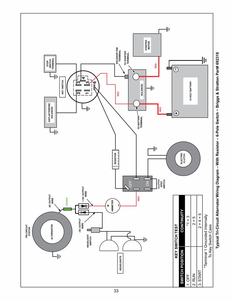
Typ
ical
Tri
-Cir
cuit
Alt
ern
ato
r Wir
ing
Dia
gra
m –
Wit
h R
esis
tor
– 6-
Po
le S
wit
ch −
Bri
gg
s &
Str
atto
n P
art#
692
318
KE
Y S
WIT
CH
TE
ST
SW
ITC
H P
OS
ITIO
NC
ON
TIN
UIT
Y
1. O
ff
*1 +
3
2. R
UN
2 +
5
3. S
TAR
T2
+ 4
+ 5
*Ter
min
al 1
Gro
unde
d In
tern
ally
To
Key
Sw
itch
Cas
e
ALT
ER
NA
TOR
KE
Y S
WIT
CH
AN
TI-
AF
TE
RF
IRE
S
OL
EN
OID
SO
LE
NO
ID T
AB
T
ER
MIN
AL
TO S
TAR
TE
R
TE
RM
INA
L
SO
LE
NO
IDTO
BA
TT
ER
Y
TE
RM
INA
L
12 V
OLT
BA
TT
ER
Y
HE
AD
LIG
HT
S
AM
ME
TE
R
EL
EC
TR
IC
CL
UT
CH
AC
OU
TP
UT
W
IRE
TR
I-C
IRC
UIT
S
TATO
R
HE
AD
LIG
HT
S
WIT
CH
+ D
C O
UT
PU
T
WIR
E
- D
C O
UT
PU
T
WIR
E
CL
UT
CH
D
PD
T
SW
ITC
H
RE
SIS
TOR
STA
RT
ER
M
OTO
R
STO
P
SW
ITC
H
TE
RM
INA
L
GR
EE
N
RE
D
RE
D
RE
D
RE
D
34
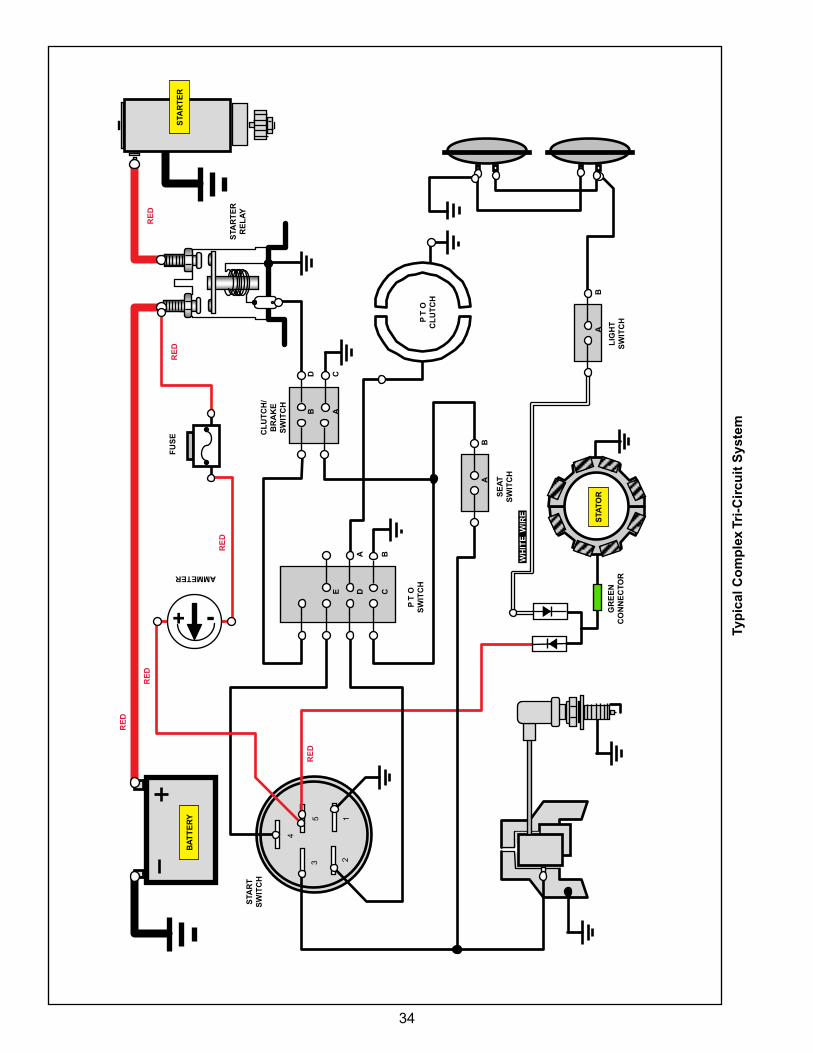
Typ
ical
Co
mp
lex
Tri-
Cir
cuit
Sys
tem
4
35
21
-+
BA
CDE
STA
RT
S
WIT
CH
BA
TT
ER
Y
STA
TOR
STA
RT
ER
STA
RT
ER
R
EL
AY
LIG
HT
S
WIT
CH
CL
UT
CH
/B
RA
KE
S
WIT
CH
P
T O
S
WIT
CH
GR
EE
N
CO
NN
EC
TOR
P T
O
CL
UT
CH
AMMETER
FU
SE
CD
AB
BA
BA
SE
AT
S
WIT
CH
RE
D
WH
ITE
WIR
E
RE
D
RE
D
RE
D
RE
D
RE
D
35
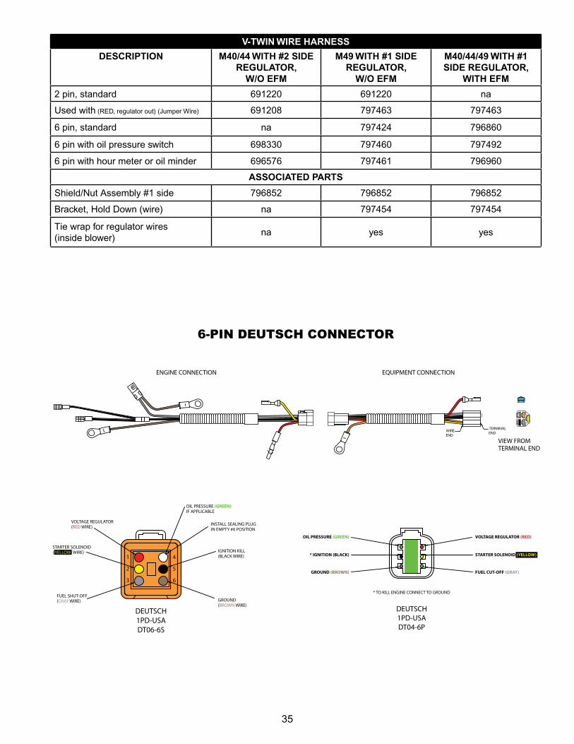
V-TWIN WIRE HARNESS
DESCRIPTION M40/44 WITH #2 SIDE REGULATOR,
W/O EFM
M49 WITH #1 SIDE REGULATOR,
W/O EFM
M40/44/49 WITH #1 SIDE REGULATOR,
WITH EFM
2 pin, standard 691220 691220 na
Used with (RED, regulator out) (Jumper Wire) 691208 797463 797463
6 pin, standard na 797424 796860
6 pin with oil pressure switch 698330 797460 797492
6 pin with hour meter or oil minder 696576 797461 796960
ASSOCIATED PARTS
Shield/Nut Assembly #1 side 796852 796852 796852
Bracket, Hold Down (wire) na 797454 797454
Tie wrap for regulator wires (inside blower)
na yes yes
VIEW FROMTERMINAL END
TERMINALEND
WIREEND
ENGINE CONNECTION
DEUTSCH1PD-USADT06-6S
DEUTSCH1PD-USADT04-6P
* TO KILL ENGINE CONNECT TO GROUND
EQUIPMENT CONNECTION
6-Pin Deutsch Connections
OIL PRESSURE (GREEN)
* IGNITION (BLACK)
GROUND (BROWN)
VOLTAGE REGULATOR (RED)
STARTER SOLENOID (YELLOW)
FUEL CUT-OFF (GRAY)
VOLTAGE REGULATOR(RED WIRE)
1
2
3
4
5
6
STARTER SOLENOID( YELLOW WIRE)
FUEL SHUT-OFF(GRAY WIRE)
INSTALL SEALING PLUGIN EMPTY #6 POSITION
IGNITION KILL(BLACK WIRE)
GROUND(BROWN WIRE)
OIL PRESSURE (GREEN)IF APPLICABLE
6‑PIN DEUTSCH CONNECTOR
36
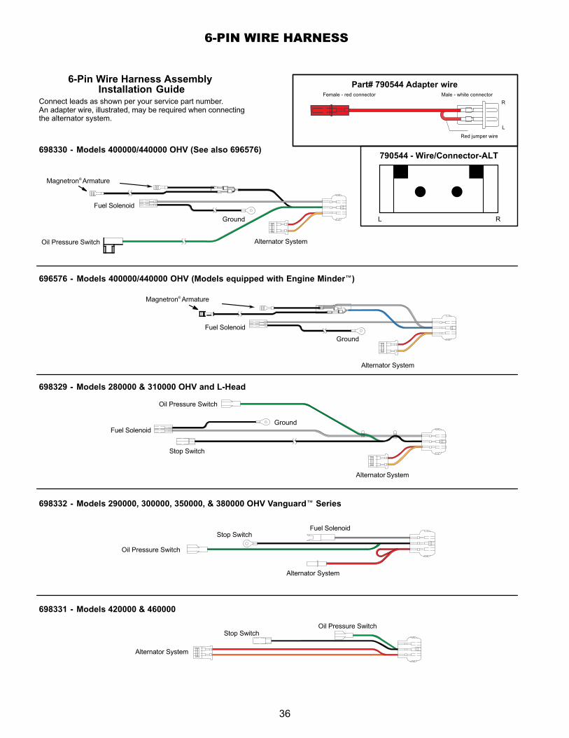
Part# 790544 Adapter wire6-Pin Wire Harness Assembly Installation Guide
Connect leads as shown per your service part number. An adapter wire, illustrated, may be required when connectingthe alternator system.
698330 - Models 400000/440000 OHV (See also 696576)
Magnetron® Armature
Oil Pressure Switch
Fuel Solenoid
Ground
Alternator System
L R
696576 - Models 400000/440000 OHV (Models equipped with Engine Minder )
Fuel Solenoid
Ground
Alternator System
Male - white connector
R
Red jumper wire
L
Female - red connector
790544 - Wire/Connector-ALT
698329 - Models 280000 & 310000 OHV and L-Head
698332 - Models 290000, 300000, 350000, & 380000 OHV Vanguard Series
698331 - Models 420000 & 460000
Alternator System
Alternator System
Fuel Solenoid
Fuel Solenoid
Ground
Oil Pressure Switch
Oil Pressure Switch
Oil Pressure Switch
Alternator System
Stop Switch
Stop Switch
Stop Switch
Magnetron® Armature
6‑PIN WIRE HARNESS
37
GREEN
GREEN
BLACK
GRAY
RED ORANGE
ORANGE
RED
BLACK
TOP
OPEN
BOTTOM
GRAY
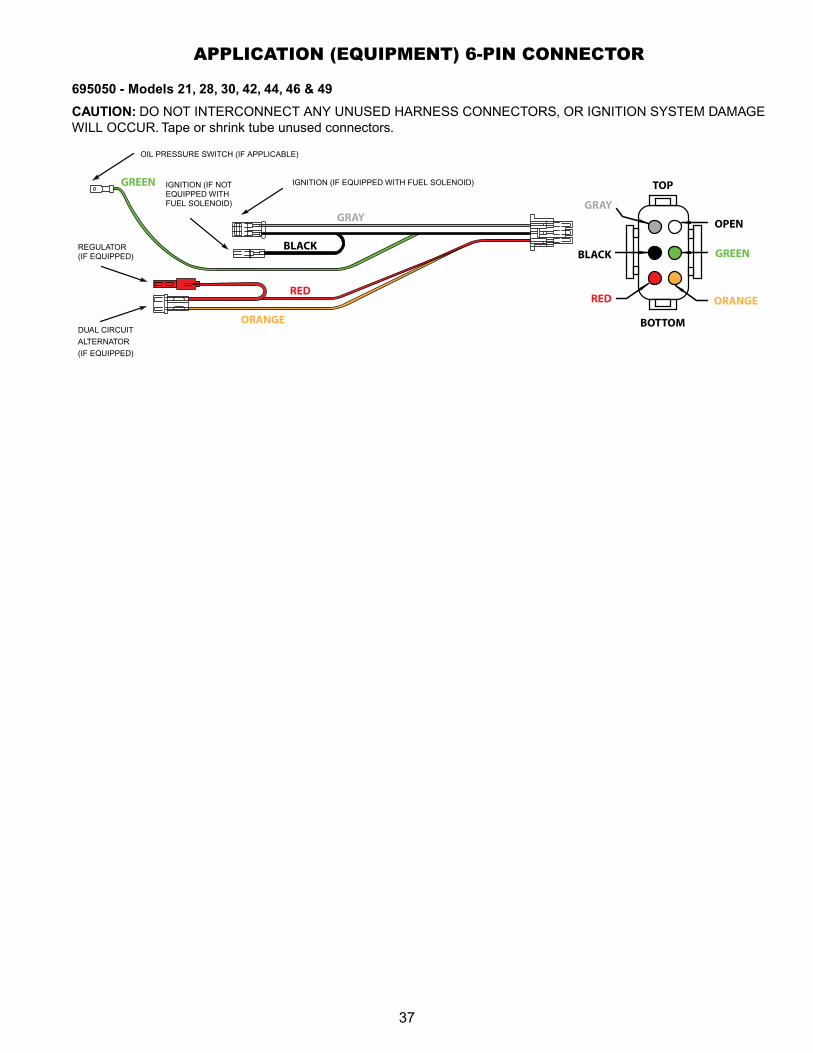
APPLICATION (EQUIPMENT) 6‑PIN CONNECTOR
695050 - Models 21, 28, 30, 42, 44, 46 & 49
CAUTION: DO NOT INTERCONNECT ANY UNUSED HARNESS CONNECTORS, OR IGNITION SYSTEM DAMAGE WILL OCCUR. Tape or shrink tube unused connectors.
IGNITION (If EQUIPPED WITH fUEL SOLENOID)
OIL PRESSURE SWITCH (If APPLICABLE)
IGNITION (If NOT EQUIPPED WITH fUEL SOLENOID)
REGULATOR (If EQUIPPED)
DUAL CIRCUIT
ALTERNATOR
(If EQUIPPED)
38
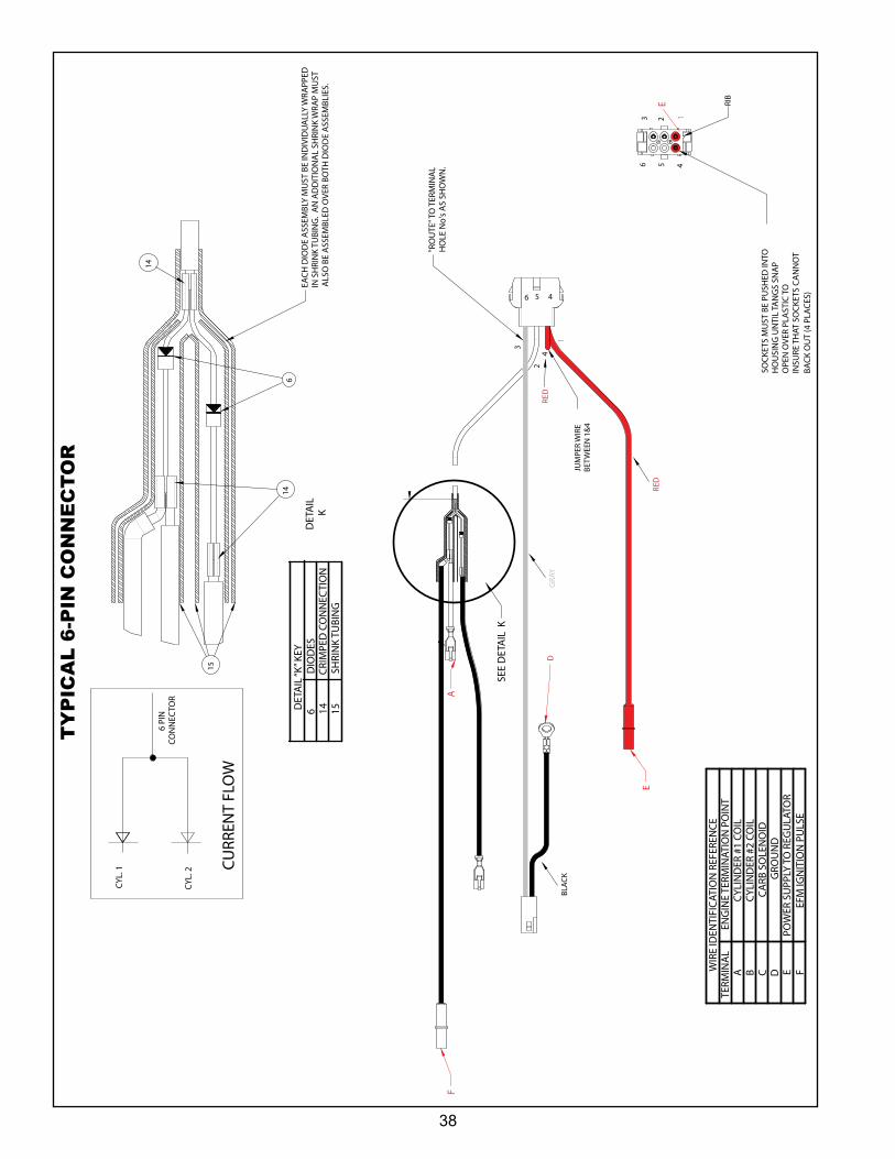
WIR
E ID
ENTI
FIC
ATIO
N R
EFER
ENC
ETE
RMIN
AL
ENG
INE
TERM
INAT
ION
PO
INT
AC
YLIN
DER
#1
COIL
BC
YLIN
DER
#2
COIL
CC
ARB
SO
LEN
OID
DG
ROU
ND
EPO
WER
SU
PPLY
TO
REG
ULA
TOR
FEF
M IG
NIT
ION
PU
LSE
6 PI
NCO
NN
ECTO
R
CYL
. 1
CYL
. 2
CU
RREN
T FL
OW
SEE
DET
AIL
K
1
2
3
4
F
DET
AIL
K
614
15
14
EAC
H D
IOD
E A
SSEM
BLY
MU
ST B
E IN
DIV
IDU
ALL
Y W
RAPP
ED
IN S
HRI
NK
TUBI
NG
. A
N A
DD
ITIO
NA
L SH
RIN
K W
RAP
MU
ST
ALS
O B
E A
SSEM
BLED
OVE
R BO
TH D
IOD
E A
SSEM
BLIE
S.
"RO
UTE
" TO
TER
MIN
AL
HO
LE N
o's
AS
SHO
WN
.
JUM
PER
WIR
EBE
TWEE
N 1
&4
GRA
Y
123
456
SOC
KETS
MU
ST B
E PU
SHED
INTO
HO
USI
NG
UN
TIL
TAN
GS
SNA
P O
PEN
OVE
R PL
AST
IC T
O IN
SURE
TH
AT S
OC
KETS
CA
NN
OT
BA
CK
OU
T (4
PLA
CES
)
RIB
A
D
E
E
46 5D
ETA
IL “K
” KEY
6D
IOD
ES14
CRI
MPE
D C
ON
NEC
TIO
N15
SHRI
NK
TUBI
NG
RED
BLA
CK
RED
TY
PIC
AL
6‑P
IN C
ON
NE
CT
OR
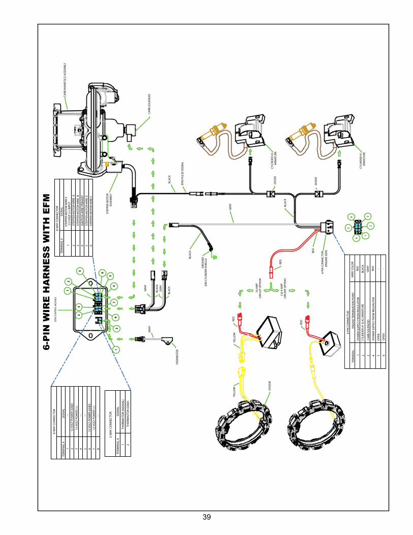
39
2
3
6
7
12
23
67
12
3
45
6
GRO
UN
D(O
N C
YLIN
DER
SH
IELD
)
STAT
OR
THER
MIS
TER
6 PI
N C
ON
NEC
TOR
(EN
GIN
E SI
DE)
CYLI
ND
ER #
1A
RMAT
URE
CYLI
ND
ER #
2A
RMAT
URE
CARB
MA
NIF
OLD
ASS
EMBL
Y
STEP
PER
MO
TOR
ASS
EMBL
Y
CARB
SO
LEN
OID
2-W
AY C
ON
NEC
TOR
TERM
INA
L #
SIG
NA
L
1TH
ERM
ISTO
R (S
IGN
AL)
2TH
ERM
ISTO
R (G
ND
)
1
23
4
56
RED
BLAC
K
RED
GRA
Y
BLAC
K
BLAC
K
BLAC
KG
RAY
GRA
YG
RAY
RED
YELL
OW
YELL
OW
BLAC
K
1 2 3 4 5 6
8-W
AY C
ON
NEC
TOR
TERM
INA
L #
SIG
NA
LST
EPPE
R M
OTO
R W
IRE
E
STEP
PER
MO
TOR
WIR
E A
STEP
PER
MO
TOR
WIR
E B
IGN
ITIO
N W
IRE
PRIM
ARY
STEP
PER
MO
TOR
WIR
E D
STEP
PER
MO
TOR
WIR
E C
(12
VOLT
(+) I
NPU
T
6 PI
N C
ON
NEC
TOR
TERM
INA
LEN
GIN
E TE
RMIN
ATIO
N P
OIN
T
1PO
WER
SU
PPLY
FRO
M R
EGU
LATO
R
2CY
LIN
DER
#1
& #
2 A
RMAT
URE
3CA
RB S
OLE
NO
ID
4PO
WER
SU
PPLY
FRO
M R
EGU
ALT
OR
5O
PEN
6O
PEN
WIR
E CO
LOR
RED
BLAC
K
GRA
Y
RED - -
RED
16 A
MP
CIRC
UIT
OPT
ION
5 &
9 A
MP
CIRC
UIT
OPT
ION
EFM
PU
LSE
SIG
NA
L
DIO
DE
DIO
DE
1 212
VO
LT P
OW
ER (G
ND
)3
12 V
OLT
PO
WER
(+)
4 5 612
VO
LT P
OW
ER (G
ND
)
712
VO
LT P
OW
ER (+
)8
------
---
---
8-W
AY C
ON
NEC
TOR
TERM
INA
L #
SIG
NA
L
EFM
CO
NTR
OL
MO
DU
LE
6‑P
IN W
IRE
HA
RN
ES
S W
ITH
EF
M
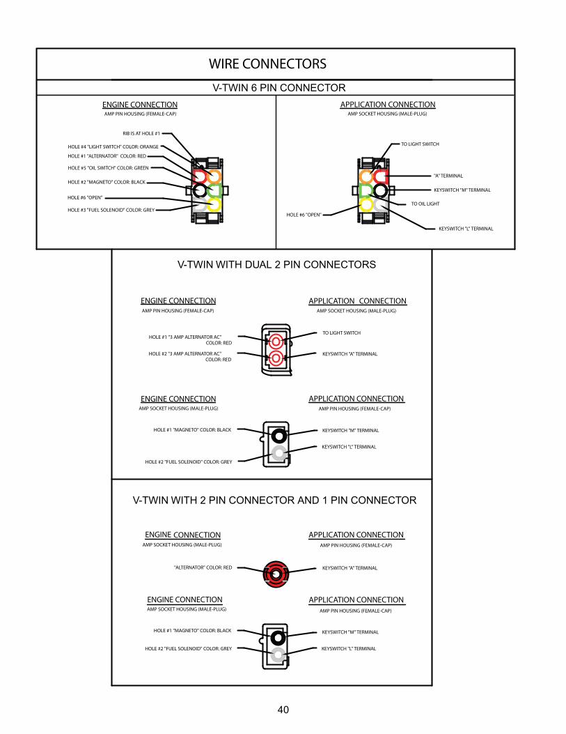
40
V-TWIN 6 PIN CONNECTOR
V-TWIN WITH DUAL 2 PIN CONNECTORS
V-TWIN WITH 2 PIN CONNECTOR AND 1 PIN CONNECTOR
HOLE #2 "3 AMP ALTERNATOR AC" COLOR: RED
HOLE #1 "MAGNETO" COLOR: BLACK
HOLE #2 "FUEL SOLENOID" COLOR: GREY
"ALTERNATOR" COLOR: RED
WIRE CONNECTORS
KEYSWITCH "A" TERMINAL
ENGINE CONNECTION APPLICATION CONNECTION
ENGINE CONNECTION APPLICATION CONNECTION
ENGINE CONNECTION APPLICATION CONNECTION
ENGINE CONNECTION APPLICATION CONNECTION
AMP PIN HOUSING (FEMALE-CAP)
AMP SOCKET HOUSING (MALE-PLUG)
AMP SOCKET HOUSING (MALE-PLUG) AMP PIN HOUSING (FEMALE-CAP)
AMP PIN HOUSING (FEMALE-CAP)
ENGINE CONNECTIONAMP PIN HOUSING (FEMALE-CAP)
APPLICATION CONNECTIONAMP SOCKET HOUSING (MALE-PLUG)
KEYSWITCH "M" TERMINAL
KEYSWITCH "L" TERMINAL
HOLE #1 "MAGNETO" COLOR: BLACK
HOLE #2 "FUEL SOLENOID" COLOR: GREY
AMP SOCKET HOUSING (MALE-PLUG)
KEYSWITCH "M" TERMINAL
KEYSWITCH "L" TERMINAL
HOLE #1 "3 AMP ALTERNATOR AC" COLOR: RED
AMP SOCKET HOUSING (MALE-PLUG)
AMP PIN HOUSING (FEMALE-CAP)
TO LIGHT SWITCH
KEYSWITCH "A" TERMINAL
TO OIL LIGHT
TO LIGHT SWITCH
"A" TERMINAL
KEYSWITCH "L" TERMINAL
KEYSWITCH "M" TERMINAL
HOLE #1 "ALTERNATOR" COLOR: RED
HOLE #2 "MAGNETO" COLOR: BLACK
HOLE #3 "FUEL SOLENOID" COLOR: GREY
HOLE #4 "LIGHT SWITCH" COLOR: ORANGE
HOLE #5 "OIL SWITCH" COLOR: GREEN
HOLE #6 "OPEN"
RIB IS AT HOLE #1
HOLE #6 "OPEN"
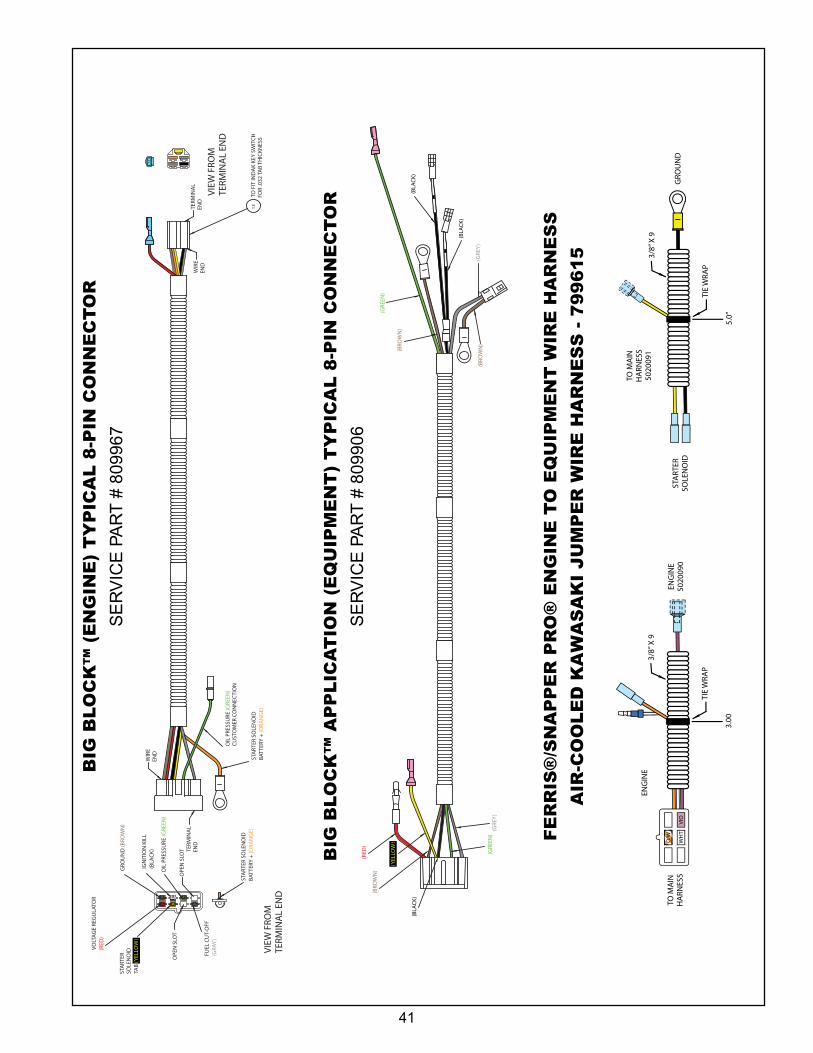
41
VIEW
FRO
MTE
RMIN
AL
END
VIEW
FRO
MTE
RMIN
AL
END
OIL
PRE
SSU
RE (G
REEN
)
13
STA
RTER
SO
LEN
OID
BATT
ERY
+ (O
RAN
GE)
OIL
PRE
SSU
RE (G
REEN
)C
UST
OM
ER C
ON
NEC
TIO
N
TO F
IT IN
DA
K KE
Y SW
ITC
HFO
R .0
32 T
AB
THIC
KNES
S
TERM
INA
LEN
DW
IRE
END
TERM
INA
LEN
D
WIR
EEN
D
VOLT
AG
E RE
GU
LATO
R(R
ED)
GRO
UN
D (B
ROW
N)
IGN
ITIO
N K
ILL
(BLA
CK)
STA
RTER
SOLE
NO
IDTA
B (Y
ELLO
W)
FUEL
CU
T-O
FF(G
RAY
)
OPE
N S
LOT
OPE
N S
LOT
(RED
)
(YEL
LOW
)
(BRO
WN
)
(BLA
CK)
(GRE
EN)
(GRE
Y)
(GRE
EN)
(BRO
WN
)
(BRO
WN
)(G
REY
)
(BLA
CK)
(BLA
CK)
STA
RTER
SO
LEN
OID
BATT
ERY
+ (O
RAN
GE)
BIG
BLO
CK
™ (
EN
GIN
E)
TY
PIC
AL
8‑P
IN C
ON
NE
CT
OR
SE
RV
ICE
PA
RT
# 8
0996
7
BIG
BLO
CK
™ A
PP
LIC
AT
ION
(E
QU
IPM
EN
T)
TY
PIC
AL
8‑P
IN C
ON
NE
CT
OR
SE
RV
ICE
PA
RT
# 8
0990
6
TIE
WRA
P
TO M
AIN
HA
RNES
S
ENG
INE
ENG
INE
5020
090
3/8”
X 9
3.00
TIE
WRA
P
TO M
AIN
HA
RNES
S50
2009
1
STA
RTER
SOLE
NO
IDG
ROU
ND
STA
RTER
SOLE
NO
ID50
2320
6
3/8”
X 9
5.0”
Air
-Co
ole
d K
awas
aki J
um
per
Wir
e H
arn
ess
- 540
2307
Ko
hle
r En
gin
e W
ire
Har
nes
s - 5
4065
15
WHT
WHT Y
EL
WH
ITE
3”
VIO
LET
3”
VIO
LET
6”W
HIT
E 6”
ORANGE/WHITE 3”
5020
907
5100
357
5021
461
5020
914
WHT
VIO
O/W
VIO
O/W
VIO
ELS
Jum
per
- T
WR
Wir
e H
arn
ess
- 540
2519
VIEW
FRO
MTE
RMIN
AL
END
13TO
FIT
IND
AK
KEY
SWIT
CH
FOR
.032
TA
B TH
ICKN
ESS
TERM
INA
LEN
DW
IRE
END
WHT
YEL
O/W
O/W
VIO
ENG
INE
5023
171
5023
172
ORA
NG
E/W
HIT
E 6”
TO M
AIN
HA
RNES
S50
2090
650
2090
7
BLA
CK
17”
YELL
OW
14”
GRO
UN
D50
2008
7
FE
RR
IS®
/SN
AP
PE
R P
RO
® E
NG
INE
TO
EQ
UIP
ME
NT
WIR
E H
AR
NE
SS
AIR
‑CO
OL
ED
KA
WA
SA
KI
JU
MP
ER
WIR
E H
AR
NE
SS
‑ 7
99
61
5
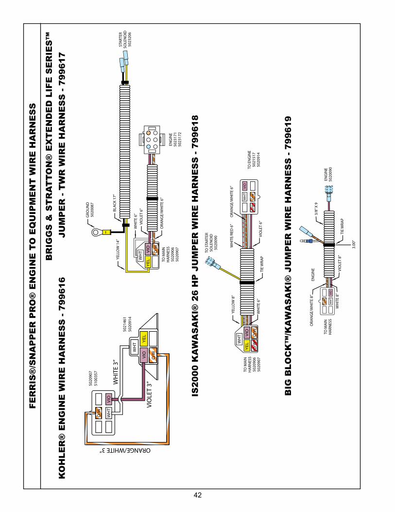
42
FE
RR
IS®
/SN
AP
PE
R P
RO
® E
NG
INE
TO
EQ
UIP
ME
NT
WIR
E H
AR
NE
SS
KO
HL
ER
® E
NG
INE
WIR
E H
AR
NE
SS
‑ 7
99
61
6
BR
IGG
S &
ST
RA
TT
ON
® E
XT
EN
DE
D L
IFE
SE
RIE
S™
JU
MP
ER
‑ T
WR
WIR
E H
AR
NE
SS
‑ 7
99
61
7
TIE
WRA
P
TO M
AIN
HA
RNES
S
ENG
INE
ENG
INE
5020
090
3/8”
X 9
3.00
TIE
WRA
P
TO M
AIN
HA
RNES
S50
2009
1
STA
RTER
SOLE
NO
IDG
ROU
ND
STA
RTER
SOLE
NO
ID50
2320
6
3/8”
X 9
5.0”
Air
-Co
ole
d K
awas
aki J
um
per
Wir
e H
arn
ess
- 540
2307
Ko
hle
r En
gin
e W
ire
Har
nes
s - 5
4065
15
WHT
WHT Y
EL
WH
ITE
3”
VIO
LET
3”
VIO
LET
6”W
HIT
E 6”
ORANGE/WHITE 3”
5020
907
5100
357
5021
461
5020
914
WHT
VIO
O/W
VIO
O/W
VIO
ELS
Jum
per
- T
WR
Wir
e H
arn
ess
- 540
2519
VIEW
FRO
MTE
RMIN
AL
END
13TO
FIT
IND
AK
KEY
SWIT
CH
FOR
.032
TA
B TH
ICKN
ESS
TERM
INA
LEN
DW
IRE
END
WHT
YEL
O/W
O/W
VIO
ENG
INE
5023
171
5023
172
ORA
NG
E/W
HIT
E 6”
TO M
AIN
HA
RNES
S50
2090
650
2090
7
BLA
CK
17”
YELL
OW
14”
GRO
UN
D50
2008
7
TIE
WRA
P
TO M
AIN
HA
RNES
S
ENG
INE
ENG
INE
5020
090
3/8”
X 9
3.00
TIE
WRA
P
TO M
AIN
HA
RNES
S50
2009
1
STA
RTER
SOLE
NO
IDG
ROU
ND
STA
RTER
SOLE
NO
ID50
2320
6
3/8”
X 9
5.0”
Air
-Co
ole
d K
awas
aki J
um
per
Wir
e H
arn
ess
- 540
2307
Ko
hle
r En
gin
e W
ire
Har
nes
s - 5
4065
15
WHT
WHT Y
EL
WH
ITE
3”
VIO
LET
3”
VIO
LET
6”W
HIT
E 6”
ORANGE/WHITE 3”
5020
907
5100
357
5021
461
5020
914
WHT
VIO
O/W
VIO
O/W
VIO
ELS
Jum
per
- T
WR
Wir
e H
arn
ess
- 540
2519
VIEW
FRO
MTE
RMIN
AL
END
13TO
FIT
IND
AK
KEY
SWIT
CH
FOR
.032
TA
B TH
ICKN
ESS
TERM
INA
LEN
DW
IRE
END
WHT
YEL
O/W
O/W
VIO
ENG
INE
5023
171
5023
172
ORA
NG
E/W
HIT
E 6”
TO M
AIN
HA
RNES
S50
2090
650
2090
7
BLA
CK
17”
YELL
OW
14”
GRO
UN
D50
2008
7
IS2
00
0 K
AW
AS
AK
I® 2
6 H
P J
UM
PE
R W
IRE
HA
RN
ES
S ‑ 7
99
61
8
TIE
WRA
P
TO M
AIN
HA
RNES
S50
2090
650
2090
7
TO E
NG
INE
5021
517
5020
914
TO E
NG
INE
5023
171
5023
172
GRO
UN
D
TO S
TART
ERSO
LEN
OID
5020
090
IS20
00 K
awas
aki 2
6 H
P J
um
per
Wir
e H
arn
ess
- 540
1951
Ko
hle
r En
gin
e W
ire
Har
nes
s - 5
4065
15
WHT
WHT Y
EL
WH
ITE
3”
VIO
LET
3”
ORANGE/WHITE 3”
5020
907
5100
357
5021
461
5020
914
VIO
O/W
VIO
Big
Blo
ck K
awas
aki J
um
per
Wir
e H
arn
ess
- 540
3929
Bri
gg
s &
Str
atto
n J
um
per
Wir
e H
arn
ess
- 540
1204
Bri
gg
s &
Str
atto
n J
um
per
Wir
e H
arn
ess
- IS2
0000
Z
VIEW
FRO
MTE
RMIN
AL
END
13TO
FIT
IND
AK
KEY
SWIT
CH
FOR
.032
TA
B TH
ICKN
ESS
TERM
INA
LEN
DW
IRE
END
O/W
WHT
VIO
O/W
O/W
WH
ITE
6”
WHT
YEL
VIO
O/W
O/W
YELL
OW
8”
WH
ITE/
RED
6”
VIO
LET
6”
TIE
WRA
P
TO M
AIN
HA
RNES
S
ENG
INE
ENG
INE
5020
090
3/8”
X 9
3.00
”
ORA
NG
E/W
HIT
E 6”
WHT
VIO
O/W
TIE
WRA
P
TO M
AIN
HA
RNES
S
GRO
UN
D50
2008
7
TOH
ARN
ESS
5023
495
5020
014
WHT
VIO
O/W
WHT
BLK
O/W
VIO
BLA
CK
9”
ORA
NG
E/W
HIT
E 8”
VIO
LET
8”W
HIT
E 8”
WHTVIO
O/W
TO M
AIN
HA
RNES
S
TO M
AIN
HA
RNES
S
TO S
TART
ERSO
LEN
OID
TIE
WRA
P
5.00
”2
X 0
3/8”
X 9
3/8”
X 9
VIO
LET
6”W
HIT
E 6”
ORA
NG
E/W
HIT
E 6”
BLA
CK
17”
YELL
OW
9”
ORA
NG
E/W
HIT
E 8”
VIO
LET
8”W
HIT
E 8”
BIG
BLO
CK
™/K
AW
AS
AK
I® J
UM
PE
R W
IRE
HA
RN
ES
S ‑ 7
99
61
9
TIE
WRA
P
TO M
AIN
HA
RNES
S50
2090
650
2090
7
TO E
NG
INE
5021
517
5020
914
TO E
NG
INE
5023
171
5023
172
GRO
UN
D
TO S
TART
ERSO
LEN
OID
5020
090
IS20
00 K
awas
aki 2
6 H
P J
um
per
Wir
e H
arn
ess
- 540
1951
Ko
hle
r En
gin
e W
ire
Har
nes
s - 5
4065
15
WHT
WHT Y
EL
WH
ITE
3”
VIO
LET
3”
ORANGE/WHITE 3”
5020
907
5100
357
5021
461
5020
914
VIO
O/W
VIO
Big
Blo
ck K
awas
aki J
um
per
Wir
e H
arn
ess
- 540
3929
Bri
gg
s &
Str
atto
n J
um
per
Wir
e H
arn
ess
- 540
1204
Bri
gg
s &
Str
atto
n J
um
per
Wir
e H
arn
ess
- IS2
0000
Z
VIEW
FRO
MTE
RMIN
AL
END
13TO
FIT
IND
AK
KEY
SWIT
CH
FOR
.032
TA
B TH
ICKN
ESS
TERM
INA
LEN
DW
IRE
END
O/W
WHT
VIO
O/W
O/W
WH
ITE
6”
WHT
YEL
VIO
O/W
O/W
YELL
OW
8”
WH
ITE/
RED
6”
VIO
LET
6”
TIE
WRA
P
TO M
AIN
HA
RNES
S
ENG
INE
ENG
INE
5020
090
3/8”
X 9
3.00
”
ORA
NG
E/W
HIT
E 6”
WHT
VIO
O/W
TIE
WRA
P
TO M
AIN
HA
RNES
S
GRO
UN
D50
2008
7
TOH
ARN
ESS
5023
495
5020
014
WHT
VIO
O/W
WHT
BLK
O/W
VIO
BLA
CK
9”
ORA
NG
E/W
HIT
E 8”
VIO
LET
8”W
HIT
E 8”
WHTVIO
O/W
TO M
AIN
HA
RNES
S
TO M
AIN
HA
RNES
S
TO S
TART
ERSO
LEN
OID
TIE
WRA
P
5.00
”2
X 0
3/8”
X 9
3/8”
X 9
VIO
LET
6”W
HIT
E 6”
ORA
NG
E/W
HIT
E 6”
BLA
CK
17”
YELL
OW
9”
ORA
NG
E/W
HIT
E 8”
VIO
LET
8”W
HIT
E 8”
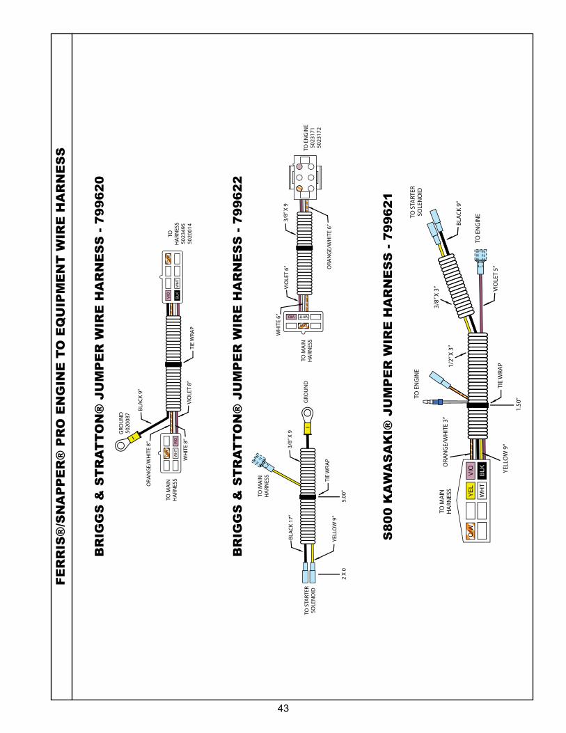
43
BR
IGG
S &
ST
RA
TT
ON
® J
UM
PE
R W
IRE
HA
RN
ES
S ‑ 7
99
62
0
BR
IGG
S &
ST
RA
TT
ON
® J
UM
PE
R W
IRE
HA
RN
ES
S ‑ 7
99
62
2
S8
00
KA
WA
SA
KI®
JU
MP
ER
WIR
E H
AR
NE
SS
‑ 7
99
62
1
TIE
WRA
P
TO M
AIN
HA
RNES
S50
2090
650
2090
7
TO E
NG
INE
5021
517
5020
914
TO E
NG
INE
5023
171
5023
172
GRO
UN
D
TO S
TART
ERSO
LEN
OID
5020
090
IS20
00 K
awas
aki 2
6 H
P J
um
per
Wir
e H
arn
ess
- 540
1951
Ko
hle
r En
gin
e W
ire
Har
nes
s - 5
4065
15
WHT
WHT Y
EL
WH
ITE
3”
VIO
LET
3”
ORANGE/WHITE 3”
5020
907
5100
357
5021
461
5020
914
VIO
O/W
VIO
Big
Blo
ck K
awas
aki J
um
per
Wir
e H
arn
ess
- 540
3929
Bri
gg
s &
Str
atto
n J
um
per
Wir
e H
arn
ess
- 540
1204
Bri
gg
s &
Str
atto
n J
um
per
Wir
e H
arn
ess
- IS2
0000
Z
VIEW
FRO
MTE
RMIN
AL
END
13TO
FIT
IND
AK
KEY
SWIT
CH
FOR
.032
TA
B TH
ICKN
ESS
TERM
INA
LEN
DW
IRE
END
O/W
WHT
VIO
O/W
O/W
WH
ITE
6”
WHT
YEL
VIO
O/W
O/W
YELL
OW
8”
WH
ITE/
RED
6”
VIO
LET
6”
TIE
WRA
P
TO M
AIN
HA
RNES
S
ENG
INE
ENG
INE
5020
090
3/8”
X 9
3.00
”
ORA
NG
E/W
HIT
E 6”
WHT
VIO
O/W
TIE
WRA
P
TO M
AIN
HA
RNES
S
GRO
UN
D50
2008
7
TOH
ARN
ESS
5023
495
5020
014
WHT
VIO
O/W
WHT
BLK
O/W
VIO
BLA
CK
9”
ORA
NG
E/W
HIT
E 8”
VIO
LET
8”W
HIT
E 8”
WHTVIO
O/W
TO M
AIN
HA
RNES
S
TO M
AIN
HA
RNES
S
TO S
TART
ERSO
LEN
OID
TIE
WRA
P
5.00
”2
X 0
3/8”
X 9
3/8”
X 9
VIO
LET
6”W
HIT
E 6”
ORA
NG
E/W
HIT
E 6”
BLA
CK
17”
YELL
OW
9”
ORA
NG
E/W
HIT
E 8”
VIO
LET
8”W
HIT
E 8”
TIE
WRA
P
TO M
AIN
HA
RNES
S50
2090
650
2090
7
TO E
NG
INE
5021
517
5020
914
TO E
NG
INE
5023
171
5023
172
GRO
UN
D
TO S
TART
ERSO
LEN
OID
5020
090
IS20
00 K
awas
aki 2
6 H
P J
um
per
Wir
e H
arn
ess
- 540
1951
Ko
hle
r En
gin
e W
ire
Har
nes
s - 5
4065
15
WHT
WHT Y
EL
WH
ITE
3”
VIO
LET
3”
ORANGE/WHITE 3”
5020
907
5100
357
5021
461
5020
914
VIO
O/W
VIO
Big
Blo
ck K
awas
aki J
um
per
Wir
e H
arn
ess
- 540
3929
Bri
gg
s &
Str
atto
n J
um
per
Wir
e H
arn
ess
- 540
1204
Bri
gg
s &
Str
atto
n J
um
per
Wir
e H
arn
ess
- IS2
0000
Z
VIEW
FRO
MTE
RMIN
AL
END
13TO
FIT
IND
AK
KEY
SWIT
CH
FOR
.032
TA
B TH
ICKN
ESS
TERM
INA
LEN
DW
IRE
END
O/W
WHT
VIO
O/W
O/W
WH
ITE
6”
WHT
YEL
VIO
O/W
O/W
YELL
OW
8”
WH
ITE/
RED
6”
VIO
LET
6”
TIE
WRA
P
TO M
AIN
HA
RNES
S
ENG
INE
ENG
INE
5020
090
3/8”
X 9
3.00
”
ORA
NG
E/W
HIT
E 6”
WHT
VIO
O/W
TIE
WRA
P
TO M
AIN
HA
RNES
S
GRO
UN
D50
2008
7
TOH
ARN
ESS
5023
495
5020
014
WHT
VIO
O/W
WHT
BLK
O/W
VIO
BLA
CK
9”
ORA
NG
E/W
HIT
E 8”
VIO
LET
8”W
HIT
E 8”
WHTVIO
O/W
TO M
AIN
HA
RNES
S
TO M
AIN
HA
RNES
S
TO S
TART
ERSO
LEN
OID
TIE
WRA
P
5.00
”2
X 0
3/8”
X 9
3/8”
X 9
VIO
LET
6”W
HIT
E 6”
ORA
NG
E/W
HIT
E 6”
BLA
CK
17”
YELL
OW
9”
ORA
NG
E/W
HIT
E 8”
VIO
LET
8”W
HIT
E 8”
TO M
AIN
HA
RNES
S
TO S
TART
ERSO
LEN
OID
TO E
NG
INE
S800
Kaw
asak
i Ju
mp
er W
ire
Har
nes
s - 5
4046
53
O/W
VIO
BLK
WHT
YEL
1/2”
X 3
”
TO E
NG
INE
TIE
WRA
P
1.50
”
3/8”
X 3
” VIO
LET
5”
YELL
OW
9”
BLA
CK
9”
ORA
NG
E/W
HIT
E 3”
FE
RR
IS®
/SN
AP
PE
R®
PR
O E
NG
INE
TO
EQ
UIP
ME
NT
WIR
E H
AR
NE
SS
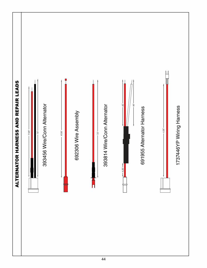
44
3934
56 W
ire/C
onn
Alte
rnat
or
6923
06 W
ire A
ssem
bly
6919
55 A
ltern
ator
Har
ness
1737
446Y
P W
iring
Har
ness
3938
14 W
ire/C
onn
Alte
rnat
or
7.12
5”
7.5”
7.5”
47.2
5”
45”
45”
4.25
”
4.25
”
ALT
ER
NA
TO
R H
AR
NE
SS
AN
D R
EPA
IR L
EA
DS
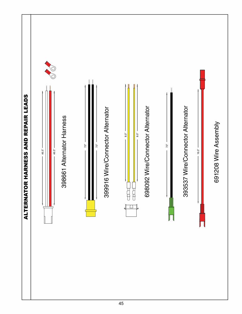
45
3935
37 W
ire/C
onne
ctor
Alte
rnat
or
3986
61 A
ltern
ator
Har
ness
3999
16 W
ire/C
onne
ctor
Alte
rnat
or
6980
92 W
ire/C
onne
ctor
Alte
rnat
or
6912
08 W
ire A
ssem
bly
46.5
”
7.0”
8.0”
7.0”
16.0
”
8.0”
7.0”
46.5
”
ALT
ER
NA
TO
R H
AR
NE
SS
AN
D R
EPA
IR L
EA
DS
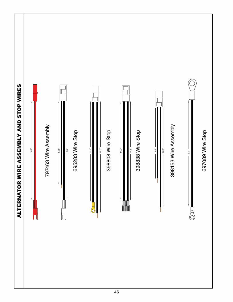
46
ALT
ER
NA
TO
R W
IRE
AS
SE
MB
LY
AN
D S
TO
P W
IRE
S
7974
63 W
ire A
ssem
bly
6952
83 W
ire S
top
6970
89 W
ire S
top
3981
53 W
ire A
ssem
bly
3988
38 W
ire S
top
3988
08 W
ire S
top
16.0
”
8.75
”
9.5”
15.0
”
13.5
”
14.5
”
20.0
”
8.5”
6.5”14
.5”
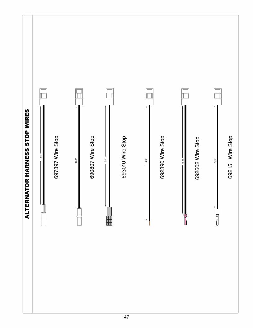
47
ALT
ER
NA
TO
R H
AR
NE
SS
ST
OP
WIR
ES
6930
10 W
ire S
top
6973
97 W
ire S
top
6923
90 W
ire S
top
6908
07 W
ire S
top
6926
02 W
ire S
top
6921
51 W
ire S
top
18.5
”
14.0
”
7.0”
15.5
”
12.2
5”
7.75
”
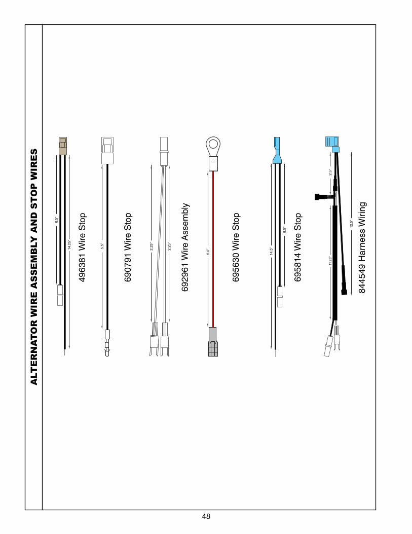
48
ALT
ER
NA
TO
R W
IRE
AS
SE
MB
LY
AN
D S
TO
P W
IRE
S
6956
30 W
ire S
top
6958
14 W
ire S
top
8445
49 H
arne
ss W
iring
6929
61 W
ire A
ssem
bly
6907
91 W
ire S
top
4963
81 W
ire S
top
2.25
”
2.25
”
8.5”
5.0”
5.5”
14.5
”
12.5
”
2.5”
11.2
5”
6.5”
14.2
5”
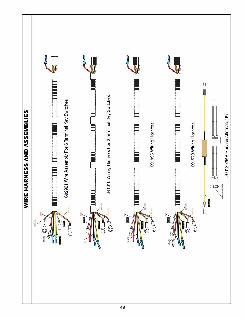
49
WIR
E H
AR
NE
SS
AN
D A
SS
EM
BL
IES
6929
61 W
ire A
ssem
bly
For
6 T
erm
inal
Key
Sw
itche
s
8413
18 W
iring
Har
ness
For
6 T
erm
inal
Key
Sw
itche
s
(YEL
LOW
)
(RED
)
WH
ITE
(ORA
NG
E)
WH
ITE
(RED
)
(BRO
WN
)
(BRO
WN
)
(ORA
NG
E)
(YEL
LOW
)
(BLA
CK)
6919
96 W
iring
Har
ness
WH
ITE
(RED
)
(BRO
WN
)
(ORA
NG
E)
(YEL
LOW
)
(BLA
CK)
6915
78 W
iring
Har
ness
WH
ITE
(RED
)
(BRO
WN
)
(ORA
NG
E)
(YEL
LOW
)
(BLA
CK)
(BLA
CK)
7001
302M
A S
ervi
ce A
ltern
ator
Kit
(Hal
ogen
Lig
ht B
ulb
)(W
ire T
ies)
(YEL
LOW
)
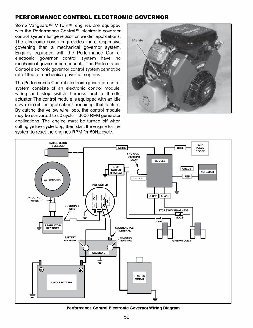
50
Some Vanguard™ V‑Twin™ engines are equipped with the Performance Control™ electronic governor control system for generator or welder applications. The electronic governor provides more responsive governing than a mechanical governor system. Engines equipped with the Performance Control electronic governor control system have no mechanical governor components. The Performance Control electronic governor control system cannot be retrofitted to mechanical governor engines.
The Performance Control electronic governor control system consists of an electronic control module, wiring and stop switch harness and a throttle actuator. The control module is equipped with an idle down circuit for applications requiring that feature. By cutting the yellow wire loop, the control module may be converted to 50 cycle – 3000 RPM generator applications. The engine must be turned off when cutting yellow cycle loop, then start the engine for the system to reset the engines RPM for 50Hz cycle.
PERFORMANCE CONTROL ELECTRONIC GOVERNOR
-
65
432
1
+
Performance Control Electronic Governor Wiring Diagram
ALTERNATOR
KEY SWITCH
CARBURETOR SOLENOID
STOP SWITCH
TERMINAL
SOLENOID TAB TERMINAL
STARTER TERMINAL
SOLENOID
BATTERY TERMINAL
STARTER MOTOR
12 VOLT BATTERY
IGNITION COILS
ACTUATOR
REGULATOR/ RECTIFIER
AC OUTPUT WIRES
IDLE DOWN
DEVICE50 CYCLE – 3000 RPM
LOOP
DIODE
DC OUTPUT WIRE
STOP SWITCH HARNESS
MODULE
DIODE
BLACKGREY
RED
GREEN
YELLOW
BLUEWHITE
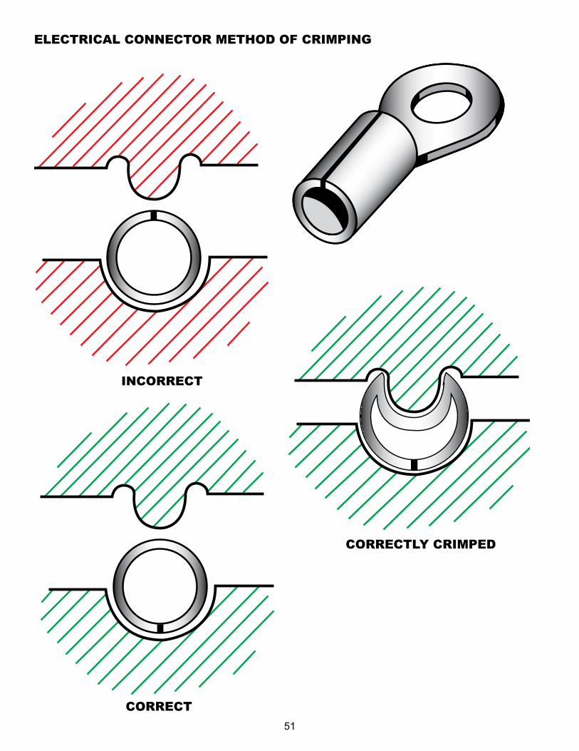
51
ELECTRICAL CONNECTOR METHOD OF CRIMPING
INCORRECT
CORRECT
CORRECTLY CRIMPED
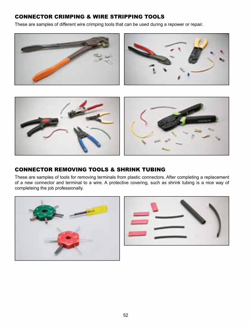
52
CONNECTOR CRIMPING & WIRE STRIPPING TOOLSThese are samples of different wire crimping tools that can be used during a repower or repair.
CONNECTOR REMOVING TOOLS & SHRINK TUBINGThese are samples of tools for removing terminals from plastic connectors. After completing a replacement of a new connector and terminal to a wire. A protective covering, such as shrink tubing is a nice way of completeing the job professionally.
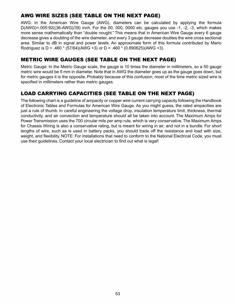
53
AWG WIRE SIzES (SEE TABLE ON THE NEXT PAGE) AWG: In the American Wire Gauge (AWG), diameters can be calculated by applying the formula D(AWG)=.005·92((36‑AWG)/39) inch. for the 00, 000, 0000 etc. gauges you use ‑1, ‑2, ‑3, which makes more sense mathematically than “double nought.” This means that in American Wire Gauge every 6 gauge decrease gives a doubling of the wire diameter, and every 3 gauge decrease doubles the wire cross sectional area. Similar to dB in signal and power levels. An approximate form of this formula contributed by Mario Rodriguez is D = .460 * (57/64)(AWG +3) or D = .460 * (0.890625)(AWG +3).
METRIC WIRE GAUGES (SEE TABLE ON THE NEXT PAGE)Metric Gauge: In the Metric Gauge scale, the gauge is 10 times the diameter in millimeters, so a 50 gauge metric wire would be 5 mm in diameter. Note that in AWG the diameter goes up as the gauge goes down, but for metric gauges it is the opposite. Probably because of this confusion, most of the time metric sized wire is specified in millimeters rather than metric gauges.
LOAD CARRYING CAPACITIES (SEE TABLE ON THE NEXT PAGE)The following chart is a guideline of ampacity or copper wire current carrying capacity following the Handbook of Electronic Tables and formulas for American Wire Gauge. As you might guess, the rated ampacities are just a rule of thumb. In careful engineering the voltage drop, insulation temperature limit, thickness, thermal conductivity, and air convection and temperature should all be taken into account. The Maximum Amps for Power Transmission uses the 700 circular mils per amp rule, which is very conservative. The Maximum Amps for Chassis Wiring is also a conservative rating, but is meant for wiring in air, and not in a bundle. for short lengths of wire, such as is used in battery packs, you should trade off the resistance and load with size, weight, and flexibility. NOTE: for installations that need to conform to the National Electrical Code, you must use their guidelines. Contact your local electrician to find out what is legal!

54
AWG gaugeConductorDiameter
Inches
ConductorDiameter
mm
Ohms per 1000 ft.
Ohms per km
Maximum amps for
chassis wiring
Maximum amps for
power transmission
Maximum frequency for 100% skin depth for solid
conductor copper
0000 0.46 11.684 0.049 0.16072 380 302 125 Hz
000 0.4096 10.40384 0.0618 0.202704 328 239 160 Hz
00 0.3648 9.26592 0.0779 0.255512 283 190 200 Hz
0 0.3249 8.25246 0.0983 0.322424 245 150 250 Hz
1 0.2893 7.34822 0.1239 0.406392 211 119 325 Hz
2 0.2576 6.54304 0.1563 0.512664 181 94 410 Hz
3 0.2294 5.82676 0.197 0.64616 158 75 500 Hz
4 0.2043 5.18922 0.2485 0.81508 135 60 650 Hz
5 0.1819 4.62026 0.3133 1.027624 118 47 810 Hz
6 0.162 4.1148 0.3951 1.295928 101 37 1100 Hz
7 0.1443 3.66522 0.4982 1.634096 89 30 1300 Hz
8 0.1285 3.2639 0.6282 2.060496 73 24 1650 Hz
9 0.1144 2.90576 0.7921 2.598088 64 19 2050 Hz
10 0.1019 2.58826 0.9989 3.276392 55 15 2600 Hz
11 0.0907 2.30378 1.26 4.1328 47 12 3200 Hz
12 0.0808 2.05232 1.588 5.20864 41 9.3 4150 Hz
13 0.072 1.8288 2.003 6.56984 35 7.4 5300 Hz
14 0.0641 1.62814 2.525 8.282 32 5.9 6700 Hz
15 0.0571 1.45034 3.184 10.44352 28 4.7 8250 Hz
16 0.0508 1.29032 4.016 13.17248 22 3.7 11 kHz
17 0.0453 1.15062 5.064 16.60992 19 2.9 13 kHz
18 0.0403 1.02362 6.385 20.9428 16 2.3 17 kHz
19 0.0359 0.91186 8.051 26.40728 14 1.8 21 kHz
20 0.032 0.8128 10.15 33.292 11 1.5 27 kHz
21 0.0285 0.7239 12.8 41.984 9 1.2 33 kHz
22 0.0254 0.64516 16.14 52.9392 7 0.92 42 kHz
23 0.0226 0.57404 20.36 66.7808 4.7 0.729 53 kHz
24 0.0201 0.51054 25.67 84.1976 3.5 0.577 68 kHz
25 0.0179 0.45466 32.37 106.1736 2.7 0.457 85 kHz
26 0.0159 0.40386 40.81 133.8568 2.2 0.361 107 kHz
27 0.0142 0.36068 51.47 168.8216 1.7 0.288 130 kHz
28 0.0126 0.32004 64.9 212.872 1.4 0.226 170 kHz
29 0.0113 0.28702 81.83 268.4024 1.2 0.182 210 kHz
30 0.01 0.254 103.2 338.496 0.86 0.142 270 kHz
31 0.0089 0.22606 130.1 426.728 0.7 0.113 340 kHz
32 0.008 0.2032 164.1 538.248 0.53 0.091 430 kHz
Metric 2.0 0.00787 0.200 169.39 555.61 0.51 0.088 440 kHz
33 0.0071 0.18034 206.9 678.632 0.43 0.072 540 kHz
Metric 1.8 0.00709 0.180 207.5 680.55 0.43 0.072 540 kHz
34 0.0063 0.16002 260.9 855.752 0.33 0.056 690 kHz
Metric 1.6 0.0063 0.16002 260.9 855.752 0.33 0.056 690 kHz
35 0.0056 0.14224 329 1079.12 0.27 0.044 870 kHz
Metric 1.4 .00551 .140 339 1114 0.26 0.043 900 kHz
36 0.005 0.127 414.8 1360 0.21 0.035 1100 kHz
Metric 1.25 .00492 0.125 428.2 1404 0.20 0.034 1150 kHz
37 0.0045 0.1143 523.1 1715 0.17 0.0289 1350 kHz
Metric 1.12 .00441 0.112 533.8 1750 0.163 0.0277 1400 kHz
38 0.004 0.1016 659.6 2163 0.13 0.0228 1750 kHz
Metric 1 .00394 0.1000 670.2 2198 0.126 0.0225 1750 kHz
39 0.0035 0.0889 831.8 2728 0.11 0.0175 2250 kHz
40 0.0031 0.07874 1049 3440 0.09 0.0137 2900 kHz
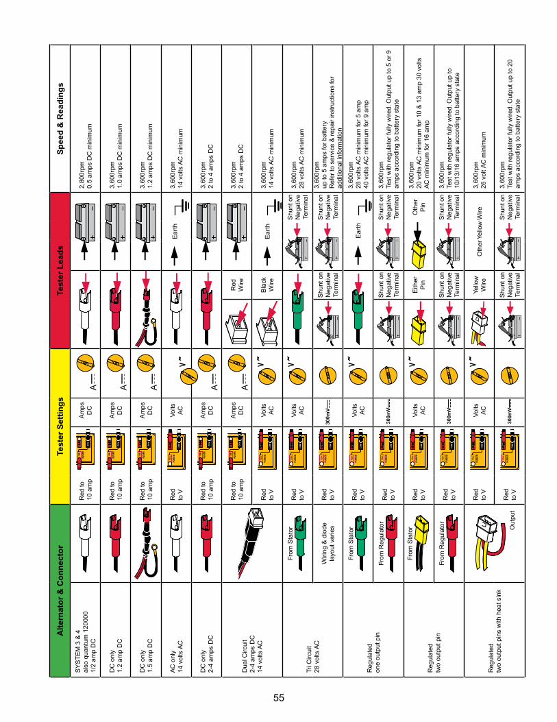
55
Alt
ern
ato
r &
Co
nn
ecto
rTe
ster
Set
tin
gs
Test
er L
ead
sS
pee
d &
Rea
din
gs
SY
ST
EM
3 &
4
also
qua
ntum
120
000
1/
2 am
p D
C
Red
to
10 a
mp
Am
ps
DC
2,80
0rpm
0.
5 am
ps D
C m
inim
um
DC
onl
y 1.
2 am
p D
CR
ed to
10
am
pA
mps
D
C3,
600r
pm
1.0
amps
DC
min
imum
DC
onl
y 1.
5 am
p D
CR
ed to
10
am
pA
mps
D
C3,
600r
pm
1.2
amps
DC
min
imum
AC
onl
y 14
vol
ts A
CR
ed
to V
Vol
ts
AC
Ear
th3,
600r
pm
14 v
olts
AC
min
imum
DC
onl
y 2‑
4 am
ps D
CR
ed to
10
am
pA
mps
D
C3,
600r
pm
2 to
4 a
mps
DC
Dua
l Circ
uit
2‑4
amps
DC
14
vol
ts A
C
Red
to
10 a
mp
Am
ps
DC
Red
W
ire3,
600r
pm
2 to
4 a
mps
DC
Red
to
VV
olts
A
CB
lack
W
ireE
arth
3,60
0rpm
14
vol
ts A
C m
inim
um
Tri C
ircui
t 28
vol
ts A
C
from
Sta
tor
Red
to
VV
olts
A
C
Shu
nt o
n N
egat
ive
Term
inal
3,60
0rpm
28
vol
ts A
C m
inim
um
Wiri
ng &
dio
de
layo
ut v
arie
sR
ed
to V
300m
VS
hunt
on
Neg
ativ
e Te
rmin
al
Shu
nt o
n N
egat
ive
Term
inal
3,60
0rpm
up
to 5
am
ps fo
r ba
ttery
R
efer
to s
ervi
ce &
rep
air
inst
ruct
ions
for
addi
tiona
l inf
orm
atio
n
Reg
ulat
ed
one
outp
ut p
in
from
Sta
tor
Red
to
VV
olts
A
CE
arth
3,60
0rpm
28
vol
ts A
C m
inim
um fo
r 5
amp
40 v
olts
AC
min
imum
for
9 am
p
from
Reg
ulat
orR
ed
to V
300m
VS
hunt
on
Neg
ativ
e Te
rmin
al
Shu
nt o
n N
egat
ive
Term
inal
3,60
0rpm
Te
st w
ith r
egul
ator
fully
wire
d. O
utpu
t up
to 5
or
9 am
ps a
ccor
ding
to b
atte
ry s
tate
Reg
ulat
ed
two
outp
ut p
in
from
Sta
tor
Red
to
VV
olts
A
CE
ither
P
inO
ther
P
in
3,60
0rpm
20
vol
ts A
C m
inim
um fo
r 10
& 1
3 am
p 30
vol
ts
AC
min
imum
for
16 a
mp
from
Reg
ulat
or
Red
to
V30
0mV
Shu
nt o
n N
egat
ive
Term
inal
Shu
nt o
n N
egat
ive
Term
inal
3,60
0rpm
Te
st w
ith r
egul
ator
fully
wire
d. O
utpu
t up
to
10/1
3/16
am
ps a
ccor
ding
to b
atte
ry s
tate
Reg
ulat
ed
two
outp
ut p
ins
with
hea
t sin
k
Out
put
Red
to
VV
olts
A
CYe
llow
W
ireO
ther
Yel
low
Wire
3,60
0rpm
26
vol
t AC
min
imum
Red
to
V30
0mV
Shu
nt o
n N
egat
ive
Term
inal
Shu
nt o
n N
egat
ive
Term
inal
3,60
0rpm
Te
st w
ith r
egul
ator
fully
wire
d. O
utpu
t up
to 2
0 am
ps a
ccor
ding
to b
atte
ry s
tate
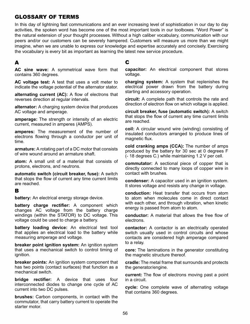
56
AAC sine wave: A symmetrical wave form that contains 360 degrees.
AC voltage test: A test that uses a volt meter to indicate the voltage potential of the alternator stator.
alternating current (AC): A flow of electrons that reverses direction at regular intervals.
alternator: A charging system device that produces AC voltage and amperage.
amperage: The strength or intensity of an electric current, measured in amperes (AMPS).
amperes: The measurement of the number of electrons flowing through a conductor per unit of time.
armature: A rotating part of a DC motor that consists of wire wound around an armature shaft.
atom: A small unit of a material that consists of protons, electrons, and neutrons.
automatic switch (circuit breaker, fuse): A switch that stops the flow of current any time current limits are reached.
Bbattery: An electrical energy storage device.
battery charge rectifier: A component which changes AC voltage from the battery charge windings (within the STATOR) to DC voltage. This voltage could be used to charge a battery.
battery loading device: An electrical test tool that applies an electrical load to the battery while measuring amperage and voltage.
breaker point ignition system: An ignition system that uses a mechanical switch to control timing of ignition.
breaker points: An ignition system component that has two points (contact surfaces) that function as a mechanical switch.
bridge rectifier: A device that uses four interconnected diodes to change one cycle of AC current into two DC pulses.
brushes: Carbon components, in contact with the commutator, that carry battery current to operate the starter motor.
Ccapacitor: An electrical component that stores voltage.
charging system: A system that replenishes the electrical power drawn from the battery during starting and accessory operation.
circuit: A complete path that controls the rate and direction of electron flow on which voltage is applied.
circuit breaker, fuse (automatic switch): A switch that stops the flow of current any time current limits are reached.
coil: A circular wound wire (winding) consisting of insulated conductors arranged to produce lines of magnetic flux.
cold cranking amps (CCA): The number of amps produced by the battery for 30 sec at 0 degrees f (‑ 18 degrees C.) while maintaining 1.2 V per cell.
commutator: A sectional piece of copper that is directly connected to many loops of copper wire in contact with brushes.
condenser: A capacitor used in an ignition system. It stores voltage and resists any change in voltage.
conduction: Heat transfer that occurs from atom to atom when molecules come in direct contact with each other, and through vibration, when kinetic energy is passed from atom to atom.
conductor: A material that allows the free flow of electrons.
contactor: A contactor is an electrically operated switch usually used in control circuits and whose contacts are considered high amperage compared to a relay.
core: The laminations in the generator constituting the magnetic structure thereof.
cradle: The metal frame that surrounds and protects the generator/engine.
current: The flow of electrons moving past a point in a circuit.
cycle: One complete wave of alternating voltage that contains 360 degrees.
GLOSSARY OF TERMSIn this day of lightning fast communications and an ever increasing level of sophistication in our day to day activities, the spoken word has become one of the most important tools in our toolboxes. “Word Power” is the natural extension of your thought processes. Without a high caliber vocabulary, communication with our peers and/or our customers can be severely hampered. Customers will measure us more than we might imagine, when we are unable to express our knowledge and expertise accurately and concisely. Exercising the vocabulary is every bit as important as learning the latest new service procedure.
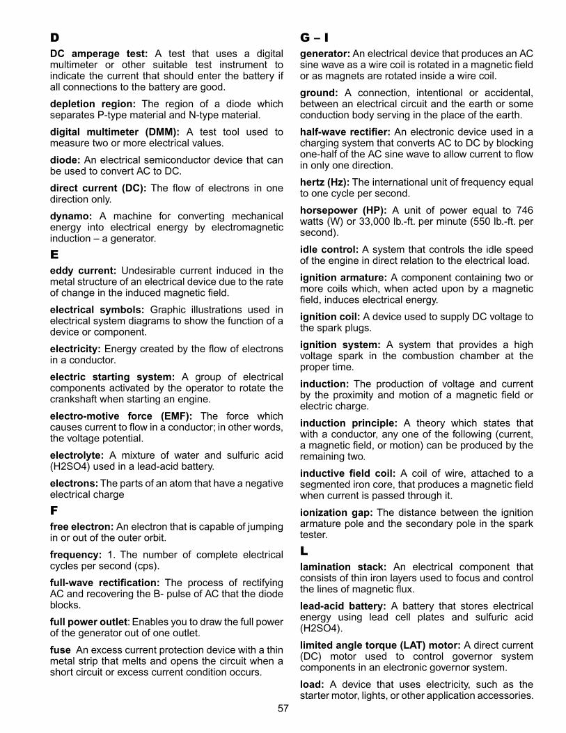
57
DDC amperage test: A test that uses a digital multimeter or other suitable test instrument to indicate the current that should enter the battery if all connections to the battery are good.
depletion region: The region of a diode which separates P‑type material and N‑type material.
digital multimeter (DMM): A test tool used to measure two or more electrical values.
diode: An electrical semiconductor device that can be used to convert AC to DC.
direct current (DC): The flow of electrons in one direction only.
dynamo: A machine for converting mechanical energy into electrical energy by electromagnetic induction – a generator.
Eeddy current: Undesirable current induced in the metal structure of an electrical device due to the rate of change in the induced magnetic field.
electrical symbols: Graphic illustrations used in electrical system diagrams to show the function of a device or component.
electricity: Energy created by the flow of electrons in a conductor.
electric starting system: A group of electrical components activated by the operator to rotate the crankshaft when starting an engine.
electro-motive force (EMF): The force which causes current to flow in a conductor; in other words, the voltage potential.
electrolyte: A mixture of water and sulfuric acid (H2SO4) used in a lead‑acid battery.
electrons: The parts of an atom that have a negative electrical charge
Ffree electron: An electron that is capable of jumping in or out of the outer orbit.
frequency: 1. The number of complete electrical cycles per second (cps).
full-wave rectification: The process of rectifying AC and recovering the B‑ pulse of AC that the diode blocks.
full power outlet: Enables you to draw the full power of the generator out of one outlet.
fuse An excess current protection device with a thin metal strip that melts and opens the circuit when a short circuit or excess current condition occurs.
G – Igenerator: An electrical device that produces an AC sine wave as a wire coil is rotated in a magnetic field or as magnets are rotated inside a wire coil.
ground: A connection, intentional or accidental, between an electrical circuit and the earth or some conduction body serving in the place of the earth.
half-wave rectifier: An electronic device used in a charging system that converts AC to DC by blocking one‑half of the AC sine wave to allow current to flow in only one direction.
hertz (Hz): The international unit of frequency equal to one cycle per second.
horsepower (HP): A unit of power equal to 746 watts (W) or 33,000 lb.‑ft. per minute (550 lb.‑ft. per second).
idle control: A system that controls the idle speed of the engine in direct relation to the electrical load.
ignition armature: A component containing two or more coils which, when acted upon by a magnetic field, induces electrical energy.
ignition coil: A device used to supply DC voltage to the spark plugs.
ignition system: A system that provides a high voltage spark in the combustion chamber at the proper time.
induction: The production of voltage and current by the proximity and motion of a magnetic field or electric charge.
induction principle: A theory which states that with a conductor, any one of the following (current, a magnetic field, or motion) can be produced by the remaining two.
inductive field coil: A coil of wire, attached to a segmented iron core, that produces a magnetic field when current is passed through it.
ionization gap: The distance between the ignition armature pole and the secondary pole in the spark tester.
Llamination stack: An electrical component that consists of thin iron layers used to focus and control the lines of magnetic flux.
lead-acid battery: A battery that stores electrical energy using lead cell plates and sulfuric acid (H2SO4).
limited angle torque (LAT) motor: A direct current (DC) motor used to control governor system components in an electronic governor system.
load: A device that uses electricity, such as the starter motor, lights, or other application accessories.
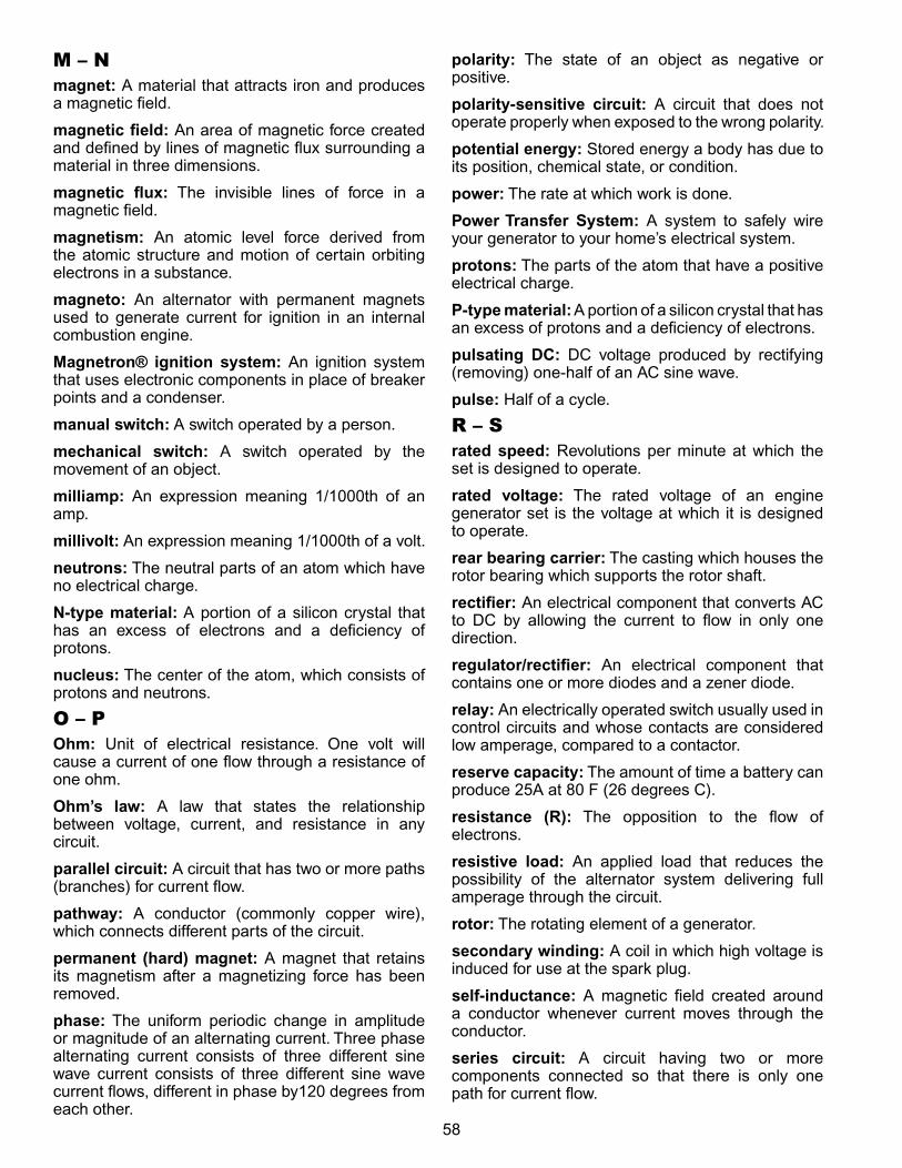
58
M – Nmagnet: A material that attracts iron and produces a magnetic field.
magnetic field: An area of magnetic force created and defined by lines of magnetic flux surrounding a material in three dimensions.
magnetic flux: The invisible lines of force in a magnetic field.
magnetism: An atomic level force derived from the atomic structure and motion of certain orbiting electrons in a substance.
magneto: An alternator with permanent magnets used to generate current for ignition in an internal combustion engine.
Magnetron® ignition system: An ignition system that uses electronic components in place of breaker points and a condenser.
manual switch: A switch operated by a person.
mechanical switch: A switch operated by the movement of an object.
milliamp: An expression meaning 1/1000th of an amp.
millivolt: An expression meaning 1/1000th of a volt.
neutrons: The neutral parts of an atom which have no electrical charge.
N-type material: A portion of a silicon crystal that has an excess of electrons and a deficiency of protons.
nucleus: The center of the atom, which consists of protons and neutrons.
O – POhm: Unit of electrical resistance. One volt will cause a current of one flow through a resistance of one ohm.
Ohm’s law: A law that states the relationship between voltage, current, and resistance in any circuit.
parallel circuit: A circuit that has two or more paths (branches) for current flow.
pathway: A conductor (commonly copper wire), which connects different parts of the circuit.
permanent (hard) magnet: A magnet that retains its magnetism after a magnetizing force has been removed.
phase: The uniform periodic change in amplitude or magnitude of an alternating current. Three phase alternating current consists of three different sine wave current consists of three different sine wave current flows, different in phase by120 degrees from each other.
polarity: The state of an object as negative or positive.
polarity-sensitive circuit: A circuit that does not operate properly when exposed to the wrong polarity.
potential energy: Stored energy a body has due to its position, chemical state, or condition.
power: The rate at which work is done.
Power Transfer System: A system to safely wire your generator to your home’s electrical system.
protons: The parts of the atom that have a positive electrical charge.
P-type material: A portion of a silicon crystal that has an excess of protons and a deficiency of electrons.
pulsating DC: DC voltage produced by rectifying (removing) one‑half of an AC sine wave.
pulse: Half of a cycle.
R – Srated speed: Revolutions per minute at which the set is designed to operate.
rated voltage: The rated voltage of an engine generator set is the voltage at which it is designed to operate.
rear bearing carrier: The casting which houses the rotor bearing which supports the rotor shaft.
rectifier: An electrical component that converts AC to DC by allowing the current to flow in only one direction.
regulator/rectifier: An electrical component that contains one or more diodes and a zener diode.
relay: An electrically operated switch usually used in control circuits and whose contacts are considered low amperage, compared to a contactor.
reserve capacity: The amount of time a battery can produce 25A at 80 f (26 degrees C).
resistance (R): The opposition to the flow of electrons.
resistive load: An applied load that reduces the possibility of the alternator system delivering full amperage through the circuit.
rotor: The rotating element of a generator.
secondary winding: A coil in which high voltage is induced for use at the spark plug.
self-inductance: A magnetic field created around a conductor whenever current moves through the conductor.
series circuit: A circuit having two or more components connected so that there is only one path for current flow.
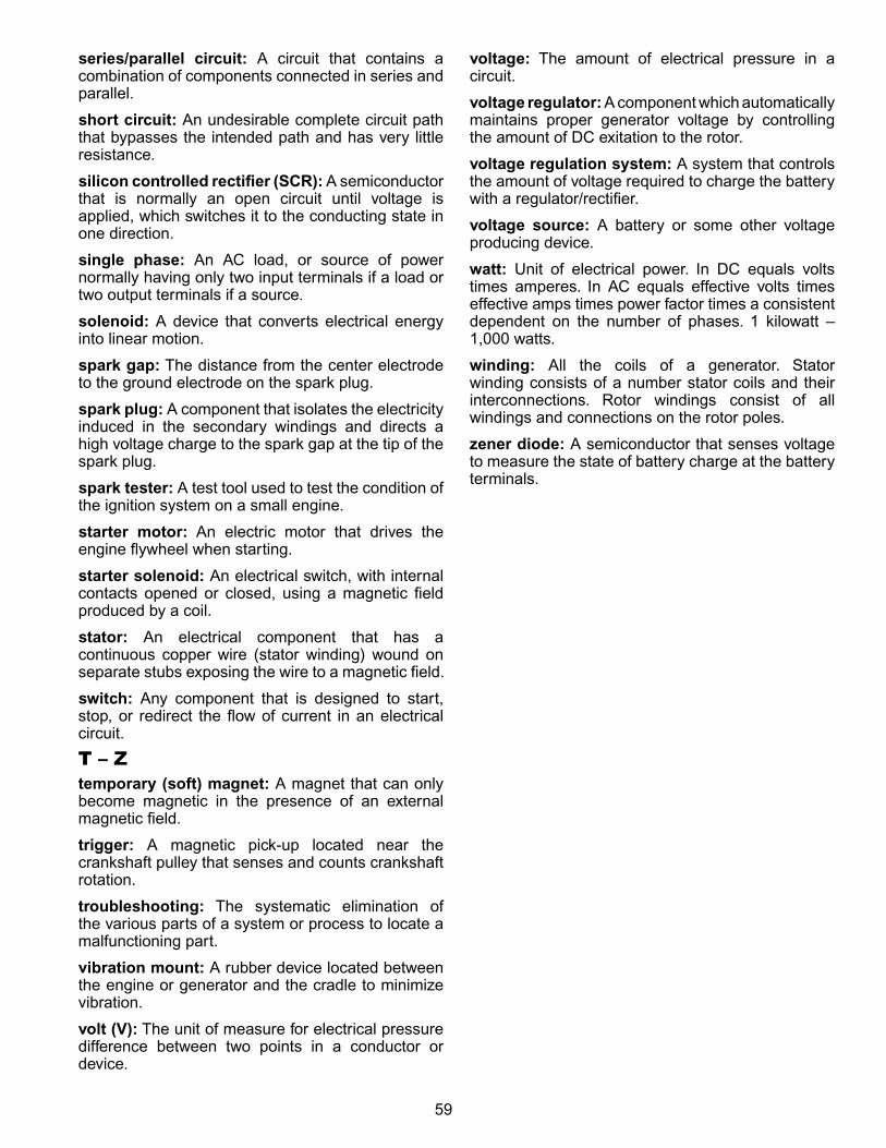
59
series/parallel circuit: A circuit that contains a combination of components connected in series and parallel.
short circuit: An undesirable complete circuit path that bypasses the intended path and has very little resistance.
silicon controlled rectifier (SCR): A semiconductor that is normally an open circuit until voltage is applied, which switches it to the conducting state in one direction.
single phase: An AC load, or source of power normally having only two input terminals if a load or two output terminals if a source.
solenoid: A device that converts electrical energy into linear motion.
spark gap: The distance from the center electrode to the ground electrode on the spark plug.
spark plug: A component that isolates the electricity induced in the secondary windings and directs a high voltage charge to the spark gap at the tip of the spark plug.
spark tester: A test tool used to test the condition of the ignition system on a small engine.
starter motor: An electric motor that drives the engine flywheel when starting.
starter solenoid: An electrical switch, with internal contacts opened or closed, using a magnetic field produced by a coil.
stator: An electrical component that has a continuous copper wire (stator winding) wound on separate stubs exposing the wire to a magnetic field.
switch: Any component that is designed to start, stop, or redirect the flow of current in an electrical circuit.
T – ztemporary (soft) magnet: A magnet that can only become magnetic in the presence of an external magnetic field.
trigger: A magnetic pick‑up located near the crankshaft pulley that senses and counts crankshaft rotation.
troubleshooting: The systematic elimination of the various parts of a system or process to locate a malfunctioning part.
vibration mount: A rubber device located between the engine or generator and the cradle to minimize vibration.
volt (V): The unit of measure for electrical pressure difference between two points in a conductor or device.
voltage: The amount of electrical pressure in a circuit.
voltage regulator: A component which automatically maintains proper generator voltage by controlling the amount of DC exitation to the rotor.
voltage regulation system: A system that controls the amount of voltage required to charge the battery with a regulator/rectifier.
voltage source: A battery or some other voltage producing device.
watt: Unit of electrical power. In DC equals volts times amperes. In AC equals effective volts times effective amps times power factor times a consistent dependent on the number of phases. 1 kilowatt – 1,000 watts.
winding: All the coils of a generator. Stator winding consists of a number stator coils and their interconnections. Rotor windings consist of all windings and connections on the rotor poles.
zener diode: A semiconductor that senses voltage to measure the state of battery charge at the battery terminals.

60
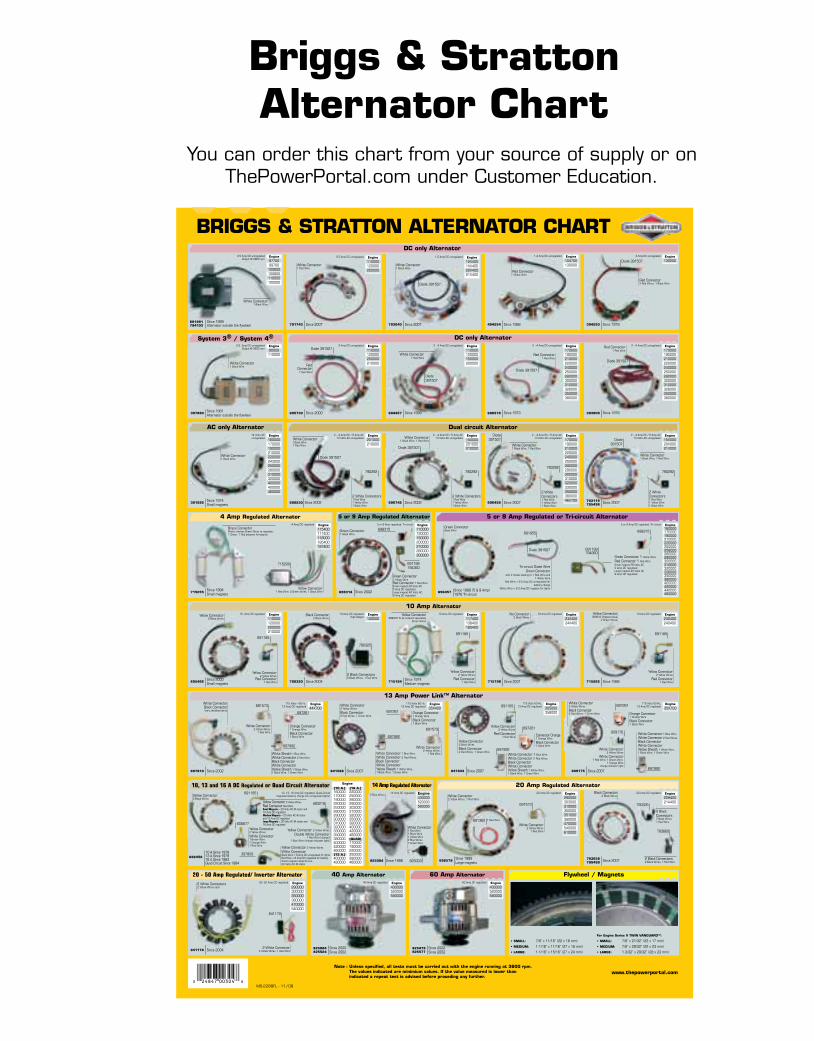
Briggs & Stratton has developed a powerful and flexible private web-based portal for its family of products, ThePowerPortal.com.
Features
➤ Secure, on-demand, 24x7 access to meaningful information and functions for all of our products.
➤ Interact via the internet for a variety of business transactions.
➤ Here is a glimpse of the available features on the brands for which you provide sales and/or service for:
• Brand specific product registration & rebate submission
• eClaim - electronic warranty claim filing for engines and end products
• E-parts - service parts and/or whole goods look-up and ordering
• Technical publications search
• Re-powering and replacement engine look-up
• 1,000s of technical and service documents
Your “One Stop” Information SourceYour “One Stop” Information SourcethePowerPortal.com
e-Parts Look-uP
what’s new?
ChanGe BranD FeatureUpdate Literature from CE on your smartphone!
Download a free app to your phone from 2dscan.com Scan the tag to right. No smartphone?
Text XXXXXXXX to 00000. Standard data rates may apply.
Update Literature fromCE on your smartphone!
Download a free app to your smartphone from 2dscan.com
Scan the tag below
BRIGGS & STRATTON ALTERNATOR CHART
(10 A.)160000170000190000220000250000280000290000303000310000320000330000350000380000400000420000460000(13 A.)400000420000
(16 A.)220000250000280000290000303000310000320000350000380000400000420000460000(QUAD)170000190000220000250000280000460000
Engine 14 Amp Regulated AlternatorEngine430000520000580000
14 Amp DC regulated
Engine35X700
115 Volts 60 Hz, 13 Amp DC regulated
Engine35X400
115 Volts 60 Hz,13 Amp DC regulated
Engine110000120000200000210000
10 Amp DC regulated
Engine170000190000210000220000240000250000280000300000310000326000350000380000
2 - 4 Amp DC unregulatedEngine90000110000
397880
White Connector1 Black Wire
Since 1981Alternator outside the flywheel
System 3® / System 4®0.5 Amp DC unregulated
Output @ 2800 rpm
Engine9770099700100600100800110000120000
691991794103
White Connector1 Black Wire
Since 1989 Alternator outside the flywheel
0.5 Amp DC unregulatedOutput @ 2800 rpm
Engine104700130000
494254
Red Connector1 Black Wire
Since 1988
1.2 Amp DC unregulated
Engine110000120000200000210000
695730
RedConnector
1 Red Wire
Since 2000
3 Amp DC unregulated
696578 Since 1973
Engine110000120000150000200000
694457
White Connector1 Red Wire
Engine201000210000
698230
White Connector1Black Wire1 Red Wire
Since 2002
2 – 4 Amp DC / 5 Amp AC14 Volts AC unregulated
4 Amp Regulated Alternator
715194
Yellow Connector399916 Shipped loose
2 Green Wires
715262 Since 1988695466Since 2000Small magnets
Yellow Connector2 Yellow Wires
Red Connector1 Red Wire
691185
Yellow Connector2 Black Wires
841178 Since 2004
20 - 50 Amp Regulated/ Inverter Alternator
2 White Connector 4 Yellow Wires, 1 Red Wire
2 White Connectors2 Yellow Wires each
Engine430000520000580000
825084825524
Since 2000Since 2002
40 Amp Alternator40 Amp DC regulated
Flywheel / Magnets
Engine130200
394250
3 Amp DC unregulated
Engine110000120000150000200000210000280000300000
698314 Since 2002
5 or 9 Amp regulated, Tri-circuit
5 or 9 Amp Regulated Alternator
Engine150000201000210000
696742
White Connector1 Black Wire, 1 Red Wire
Since 2002
2 – 4 Amp DC / 5 Amp AC14 Volts AC unregulated
Engine120000
790320 Since 2004
10 Amp DC regulatedHigh Output
Engine170000190000210000220000240000250000280000300000310000326000350000380000
393809
2 - 4 Amp DC unregulated
715255Since 1994 Small magnets
5 or 9 Amp Regulated or Tri-circuit Alternator Engine160000170000190000210000220000250000256000280000290000300000310000320000330000350000380000400000420000440000460000696457 Since 1988 (5 & 9 Amp)
1976 Tri-circuit
Green Connector 1 Yellow Wire
Red Connector 1 Red WireSmall magnet 28 Volts AC 5 Amp DC regulatedLarge magnet 40 Volts AC 9 Amp DC regulated
691188
5 or 9 Amp DC regulated, Tri-circuit
10 A Since 197813 A Since 197916 A Since 1983Quad Circuit Since 1984
Engine115400117400118000185400187400
4 Amp DC regulated
Engine117400138400185400
Engine23X40024X400
715798
10 Amp DC regulated
Engine290000300000350000380000470000540000
20 -50 Amp DC regulated
White Connector2 Yellow Wires
1 Red Wire
White Connector2 Yellow Wires, 1 Red Wire
Engine290000303000310000350000351000380000470000540000610000
20 Amp DC regulated
696579Since 1995Large magnets
Engine44X700
697810 Since 2002
825004
Engine430000520000580000
825479825577
60 Amp Alternator
10, 13, 16 Amp DC regulated, Quad-Circuit (regulated battery charge but unregulated lights)
Yellow Connector 2 Yellow Wires
Double White Connector 1 Red Wire (charge)
1 Blue Wire (charge indicator light)
Yellow Connector 2 Yellow Wires
White Connector Black Wire = 8 Amp DC unregulated for lightsRed Wire = 8 Amp DC regulated for batterySmall magnets Quad Circuit 20 Volts AC @ stator
493219
696458
Brass ConnectorPlastic sleeves Green Wires to regulator, 1 Green, 1 Red between Armatures
10 Amp DC regulated
Since 1974 Medium magnets
Yellow Connector 399916 To be ordered separately
Green Wires
Engine230400240400
Red Connector2 Red Wires, 1 Black Wire
Green Connector1 Black Wire
Black Connector 2 Black Wires
No Connector2 Black Wires
2 Blue Wires
2 - 4 Amp DC unregulated
10 Amp DC regulated
White Connector2 Yellow Wires
Black Connector2 Red Wires, 1 Green Wire
841588 Since 2007
Yellow Connector2 Black Wires
Black Connector2 Red Wires, 1 Green Wire
White Connector2 Yellow Wires
Black Connector2 Red Wires, 1 Green Wire
841833 Since 2007
Engine305000356000
115 Volts 60 Hz, 13 Amp DC regulated
809175 Since 2007
Black Connector2 Black Wires
793658795498 Since 2007
790325
793660
2 Black Connectors 2 Black Wires, 1 Red Wire
Engine20H40021A400
20 Amp DC regulated
Green ConnectorBlack Wire
697992
691573
60 Amp DC regulated
Red Connector1 Red Wire
Green Connector1 Yellow Wire Red Connector 1 Red WireSmall magnet 28 Volts AC 5 Amp DC regulatedLarge magnet 40 Volts AC 9 Amp DC regulated
2 Black Connectors 2 Black Wires, 1 Red Wire
White Connector Black ConnectorIvory sheathed wires
Orange Connector1 Orange Wire
Black Connector1 Black Wire
691955
1 Red Wire691362
www.thepowerportal.com
Diode 391507
Diode 391507
Diode 391507
Diode 391507
Engine17000019000021000022000024000025000028000029000030000031000032000033000035000038000046X700
696459
White Connector1 Black Wire, 1 Red Wire
Since 2007
2 – 4 Amp DC / 5 Amp AC14 Volts AC unregulated
Engine15X00020X00021X000
793118795498 Since 2007
2 – 4 Amp DC / 5 Amp AC14 Volts AC unregulated
Diode 391507
Since 1979
Since 1999 Since 1978
Since 2001
Since 1998
Since 2002Since 2002
115 Volts - 60 Hz, 13 Amp DC regulated
790325
Diode 391507
Diode 391507
Diode 391507
790292
2 WhiteConnectors1 Red Wire1 Yellow Wire 1 Black Wire
790292
2 WhiteConnectors 1 Red Wire1 Yellow Wire1 Black Wire
790292
2 White Connectors1 Red Wire 1 Yellow Wire 1 Black Wire
790292
2 White Connectors 1 Red Wire1 Yellow Wire 1 Black Wire
White Connector1 Black Wire, 1 Red Wire
715200Tri-circuit Diode Wire
Green Connectorwith 2 diodes leading to 1 Red Wire and
1 White WireRed Wire = 2-5 Amp DC unregulated for
battery chargeWhite Wire = 2-5 Amp DC negative for lights
Yellow Connector2 Yellow Wires
Red Connector 1 Red Wire
691185
Yellow Connector 2 Yellow Wires
Red Connector 1 Red Wire
Yellow Connector2 Black Wires
White Sheath 1 Blue WireWhite Connector 2 Red WireBlack ConnectorWhite ConnectorYellow Sheath 1 White Wire,1 Black Wire, 1 Green Wire
Yellow Connector 2 Yellow WiresRed Connector Red WireSmall Magnets = 20 Volts AC @ stator and10 Amp DC regulatedMedium Magnets = 20 Volts AC @ statorand 13 Amp DC regulatedLarge Magnets = 30 Volts AC @ stator and16 Amp DC regulated
841170
10, 13 and 16 A DC Regulated or Quad Circuit Alternator
Diode 391507 Diode
391507
DC only Alternator
Dual circuit Alternator
10 Amp Alternator
20 Amp Regulated Alternator
691188794360
691185
Engine110000120000200000
791743 Since 2007
0.5 Amp DC unregulated
White Connector1 Red Wire
391595
White Connector1 Black Wire
Since 1974Small magnets
AC only Alternator14 Volts ACunregulated
Engine160000170000190000210000220000243000250000280000310000320000400000420000460000
13 Amp Power Link™ Alternator
697261 Orange Connector1 Orange Wire
Black Connector 1 Black Wire
697992
White Connector 1 Blue Wire,White Connector 2 Red Wires,Black ConnectorWhite ConnectorYellow Sheath 1 White Wire, 1 Black Wire, 1 Green Wire
697261
Connector Orange 1 Orange Wire
Black Connector 1 Black Wire
697992White Connector 1 Blue WireWhite Connector 2 Red WiresBlack ConnectorWhite ConnectorYellow Sheath 1 White Wire,1 Black Wire, 1 Green Wire
697261
Orange Connector1 Orange Wire
Black Connector 1 Black Wire
697992
White Connector 1 Blue WireWhite Connector 2 Red WiresBlack ConnectorWhite ConnectorYellow Sheath 1 White Wire, 1 Black Wire, 1 Green Wire
Engine12X40015X40020X40021X400
793640 Since 2007
1.5 Amp DC unregulated
White Connector1 Black Wire
Diode 391507
DC only Alternator
Yellow Connector 2 Yellow Wires
Red Connector 1 Red Wire
691185
White Connector2 Yellow Wires
White Connector1 Red Wire, 1 Brown Wire,
1 Orange Wirecharge indicator light
809176
2 Black Connectors 2 Black Wires 1 Red Wire
White Connector2 Yellow Wires,
1 Red Wire
691573
697261
White Connector2 Yellow Wires
1 Red Wire
691573
Red Connector1 Red Wire
Yellow Connector1 Red Wire, 2 Green Wires, 1 Black Wire
• SMALL: 7/8” x 11/16” (22 x 18 mm)
• MEDIUM: 1-1/16” x 11/16” (27 x 18 mm)
• LARGE: 1-1/16” x 15/16” (27 x 24 mm)
For Engine Series V TWIN VANGUARD™:
• SMALL: 7/8” x 21/32” (22 x 17 mm)
• MEDIUM: 7/8” x 29/32” (22 x 23 mm)
• LARGE: 1-3/32” x 29/32” (28 x 23 mm)
Note : Unless specified, all tests must be carried out with the engine running at 3600 rpm.The values indicated are minimium values. If the value measured is lower thanindicated a repeat test is advised before proceding any further.
698315 698315
794360
825003
White Connector 1 Red Wire1 Black Wire1 Yellow Wire2 Blue Wires1 Green Wire
Yellow Connector2 Yellow Wires
White Connector1 Brown Wire1 Orange Wire1 Red Wire
808877
397809
691185
MS-2288FL - 11/08
MS-2288FL.qxp 10/23/2008 10:24 Page 1
Briggs & stratton alternator Chart
You can order this chart from your source of supply or on ThePowerPortal.com under Customer Education.
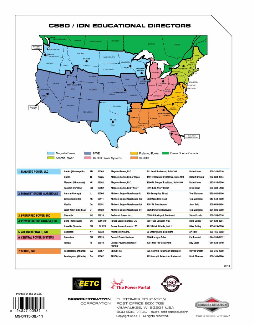
MS-0415-02/11
BRIGGS&STRATTONCORPORATION
CUSTOMER EDUCATION POST OffICE bOx 702MIlwAUkEE, wI 53201 USA800 934 7730 | [email protected] ©2011. All rights reserved.
Printed in the U.S.A.
BRITISH COLUMBIAALBERTA
SASKATCHEWAN MANITOBA
ONTARIO QUEBEC
Magneto Power
Atlantic Power
MWE
Central Power Systems
Preferred Power
SEDCO
EDWARDSVILLE
WEST VALLEY CITY
ANOKA
COLUMBUS
DELTA
Power Source Canada
9/09
CASTLETON
PENDERGRASS
MEQUON
OAKVILLE
IDN Network
TUALATINA
1. Magneto Power, LLC anoka (Minneapolis) Mn 55303 Magneto Power, LLC 911 Lund Boulevard, Suite 300 robert Moe 800-248-4016
Dallas tX 75235 Magneto Power, LLC of texas 11011 regency Crest Drive, Suite 100 robert ortolani 262-834-4394
Mequon (Milwaukee) wI 53092 Magneto Power, LLC 1000 w. Donges Bay road, Suite 100 robert Moe 262-834-4300
tualatin (Portland) or 97062 Magneto Power, LLC “west” 9991 S.w. avery Street greg Muse 800-338-5168
2. MIDweSt engIne wareHoUSe aurora (Chicago) IL 60504 Midwest engine warehouse-IL 700 enterprise Street tom Ziemann 630-862-3100
edwardsville (KC) KS 66111 Midwest engine warehouse-KS 9630 woodend road tom Ziemann 913-543-7600
Visalia Ca 93291 Midwest engine warehouse-Ca 7101 w. Doe avenue John reid 800-683-8484
west Valley City (SLC) Ut 84120 Midwest engine warehouse-Ut 3626 Parkway Boulevard tom Ziemann 801-886-2350
3. PreFerreD Power, InC Charlotte nC 28216 Preferred Power, Inc. 6509-a northpark Boulevard Steve Krcelic 800-288-5310
4. Power SoUrCe CanaDa, LtD Delta (Vancouver) BC V3M 6r9 Power Source Canada, LtD 300-1628 Derwent way Mike gulley 604-520-1294
oakville (toronto) on L6H 6X5 Power Source Canada, LtD 2815 Bristol Circle, Unit 1 Mike gulley 905-829-0006
5. atLantIC Power, InC Castleton nY 12033 atlantic Power, Inc. 20 empire State Boulevard art Falk 800-456-5692
6. CentraL Power SYSteMS Columbus oH 43228 Central Power Systems 3700 Paragon Drive Pat earnest 614-534-2152
tampa FL 33610 Central Power Systems of Florida
4751 oak Fair Boulevard ray Coyle 614-534-2140
7. SeDCo, InC Pendergrass (atlanta) ga 30567 SeDCo, Inc. 225 Henry D. robertson Boulevard wayne Crosby 800-346-4260
Pendergrass (atlanta) ga 30567 SeDCo, Inc. 225 Henry D. robertson Boulevard Mark thomas 800-346-4260
CSSD / IDN EDUCATIONAL DIRECTORS
01/11
ENGINEALTERNATOR
REPOWER GUIDE


![Step by step giude [Comic Strip]](https://img.dokumen.tips/doc/110x75/54939473b47959480e8b45e5/step-by-step-giude-comic-strip.jpg)