Embed Size (px)
Citation preview

Energy Measurement and Management
Index: MT173 – Electronic three-phase time-of-use electricity meters ..................................................... 4 1. Meter appearance ................................................ 6 1.1. Meter case.......................................................... 6 1.2. Terminal block .................................................... 6 1.2.1. Terminal block for direct connected meters .... 6 1.2.2. Terminal block of CT operated meters ............ 7 1.2.3. Auxiliary terminals ........................................... 7 1.3. Terminal block .................................................... 7 2. Meter configuration ............................................. 8 2.1. Metering elements .............................................. 8 2.2. Power supply stage ............................................ 8 2.3. Microcontroller .................................................... 8 2.3.1. Load profile recorder ....................................... 8 2.3.2. Log book.......................................................... 9 2.3.3. Billing results keeping...................................... 9 2.4. Real-time clock ................................................... 9 2.4.1. RTC back-up power supply ............................. 9 2.4.2. RTC accuracy testing ...................................... 9 2.4.3. Time-of-use registration .................................. 9 2.4.4. Maximum demand measuring ....................... 10 2.4.5. Meter billing reset .......................................... 10 2.5. LCD................................................................... 10 2.5.1. LCD testing.................................................... 10 2.5.2. Data display................................................... 10 2.5.3. Signal flags .................................................... 11 2.6. LEDs................................................................. 12 2.7. Push-buttons .................................................... 12
2.7.1. Display testing................................................12 2.7.2. Manual data display .......................................12 2.7.3. Manual meter billing reset..............................13 2.8. Communication channels..................................13 2.8.1. Optical interface .............................................13 2.8.2. RS485 interface .............................................13 2.8.3. CS interface ...................................................13 2.8.4. M-bus .............................................................14 2.8.5. Data downloaded via optical port...................14 2.8.6. Error register description................................14 2.8.7. Communication protocol ................................15 2.9. Inputs and outputs ............................................15 2.9.1. Tariff input ......................................................15 2.9.2. Impulse output................................................15 2.9.3. Tariff output ....................................................15 2.10. Detectors of opening meter cover and terminal
cover ..............................................................16 3. Antifraud protection...........................................16 3.1. Meter seals........................................................16 3.2. Always positive registration...............................16 3.3. Paswords ..........................................................16 3.4. Detector of external magnetic field ...................16 4. Meter connection ...............................................16 5. Tools....................................................................17 6. Meter maintenance.............................................17 7. Meter connection diagram ................................17 8. Technical data ....................................................18 9. Meter type designation......................................19
MT173 Three-Phase Electronic Multi Tariff Meter with Maximum Demand Indicator
Technical Description Version 1.0, 14.11.2006

Energy Measurement and Management
3 of 20
MT173 ─ Electronic three-phase electricity meters with maximum demand indicator
4 of 20
MT173 ─ Electronic three-phase electricity meters with maximum demand indicator
MT173 – Electronic three-phase time-of-use electricity meters The MT173 electronic three-phase meters are designed for measurement and registration of active or active and reactive energy in three-phase four-wire networks. They can be connected either directly or via CT. The metering and technical properties of the meters comply with the EN 50470-1 and -3 European standards for active energy meters, classes A and B, as well as with the IEC 62053-21 and IEC 62052-11 international standards for electronic meters of active energy for classes 1 and 2, and optionally with the IEC 62053-23 international standard for electronic meters of reactive energy for classes 2 and 3. A built-in time switch complies with the IEC 62054-21 and IEC 62052-21 standards. It enables energy registration in up to four tariffs. The meters are designed and manufactured in compliance with the ISO 9001 standard.
MT173 meters belong to the MT17x meters family, together with MT171 and MT172 meters. Common characteristics of the MT17x meters family are:
a. Equal measuring system b. Equal housing c. Equal terminal blocks d. Multi tariff registration (max. 4 tariffs)) e. LCD complies with VDEW requirements
The MT173 meters differ from other meters that belong to the MT17x family in:
a. Maximum demand measurement b. 4-channel load profile registration c. Communication channel:
- RS485 interface - CS interface (20-mA current loop) - M-bus
d. Log book e. Extra measures against fraud
5 of 20
MT173 ─ Electronic three-phase electricity meters with maximum demand indicator
MT173 meter properties:
• Meter accuracy Class A or B in compliance with EN 50470-3
(or 2 or 1 in compliance with IEC 62053-21) for active energy Class 3 or 2 for reactive energy (option)
• Quantity measuring Energy (active and reactive) Demand (active and reactive)
• Modes of energy measurement and registration
For one-way energy flow direction (import), with an electronic reverse running stop
For two energy flow directions (import, export) For two-way energy flow direction, with al-
ways positive registration, i.e. energy flowing in the export direction is registered as it flows in import direction too (only for active energy)
• Connection: Direct Via CT
• Networks: 3-phase 4-wire 3-phase 3-wire 1-phase 2-wire
• Meter quality: Due to high accuracy and long term stability
of the metering elements no meter recalib-ration is required over its lifetime
Long meter lifetime and high meter reliability High immunity to EMC
RTC : Accuracy better than ±3 min/year at 23°C RTC operation reserve 5 years Back-up power supply Li-battery
• Time-of-use registration (up to 4 tariffs): Tariffs change-over by internal real-time
clock Optional tariff inputs for external tariff
changeover
• LCD: Large LCD in compliance with the VDEW
requirements EDIS code for data identification
• Data display modes: Automatic cyclic data display with display
time of 5 sec. Manual data display mode (by pressing the
Scroll push-button) Optional data display when the meter is in
no-power state
• Indicators:
LCD: - Valid tariff at the moment - Meter status and alarms - Energy flow direction - Phase voltage presence and phase voltage sequence
LEDs: - Imp/kWh - Imp/kvarh (at active and reactive energy meters)
• Load profile recorder – 4 channels
• Communication channels: Infrared optical port in compliance with IEC
62056-21 for local programming and data down-loading
RS485 interface (option) CS interface (option) M-bus (option) Protocol IEC 62056 – 21, mode C
• Pulse outputs: Class A by IEC 62053-31 (option) Optomos relay with make contact (option)
• Plastic meter case: Made of high quality self-distinguishing UV
stabilized material that can be recycled Double insulation IP54 protection against dust and water
penetration (by IEC 60529)
• Detectors of meter covet and terminal block opening
• At direct connected meters: Current terminals
- Enable quick meter connection to network - Assure good connection with all types of conductors - Do not damage conductors
Potential links - Sliding self-braking potential links enable quick disconnection of current and voltage circuitry - Can be located in a terminal block com- partment or under a meter cover
6 of 20
MT173 ─ Electronic three-phase electricity meters with maximum demand indicator
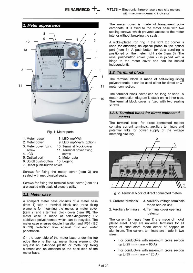
1. Meter appearance
Fig. 1: Meter parts 1. Meter base 8. LED imp/kWh 2. Meter cover 9. LED imp/kvarh (option) 3. Meter cover fixing screw
10. Terminal block cover 11. Terminal cover fixing
4. LCD screw 5. Optical port 12. Meter data 6. Scroll push-button 13. Legend 7. Reset push-button cover Screws for fixing the meter cover (item 3) are sealed with metrological seals. Screws for fixing the terminal block cover (item 11) are sealed with seals of electric utility.
1.1. Meter case A compact meter case consists of a meter base (item 1) with a terminal block and three fixing elements for mounting the meter, a meter cover (item 2) and a terminal block cover (item 10). The meter case is made of self-extinguishing UV stabilized polycarbonate which can be recycled. The meter case ensures double insulation and IP54 (IEC 60529) protection level against dust and water penetration. On the back side of the meter base under the top edge there is the top meter fixing element. On request an extended plastic or metal top fixing element can be attached to the back side of the meter base.
The meter cover is made of transparent poly-carbonate. It is fixed to the meter base with two sealing screws, which prevents access to the meter interior without breaking the seals. A nickel-plated iron ring in the right top corner is used for attaching an optical probe to the optical port (item 5). A push-button for data scrolling is positioned on the meter right side (item 6). The reset push-button cover (item 7) is joined with a hinge to the meter cover and can be sealed independently.
1.2. Terminal block The terminal block is made of self-extinguishing polycarbonate. It can be used either for direct or CT meter connection. The terminal block cover can be long or short. A meter connection diagram is stuck on its inner side. The terminal block cover is fixed with two sealing screws. 1.2.1. Terminal block for direct connected
meters The terminal block for direct connected meters contains current terminals, auxiliary terminals and potential links for power supply of the voltage metering circuitry.
Fig. 2: Terminal block of direct connected meters
1. Current terminals 3. Auxiliary voltage terminals
for an add-on unit 2. Auxiliary terminals 4. Terminal cover opening
detector
The current terminals (item 1) are made of nickel plated steel. They are universal terminals for all types of conductors made either of copper or aluminium. The current terminals are made in two sizes:
• For conductors with maximum cross section up to 25 mm2 (Imax = 85 A),
• For conductors with maximum cross section up to 35 mm2 (Imax = 120 A).
1
10
33
4 5
6
8
1111
12
13
7
29
7 of 20
MT173 ─ Electronic three-phase electricity meters with maximum demand indicator
Only one screw is used per current terminal, which makes shorter time for meter installation. Due to indirect pressure to the conductor the screw does not damage it. It makes a reliable and durable contact regardless if the conductor is made of copper or aluminium.
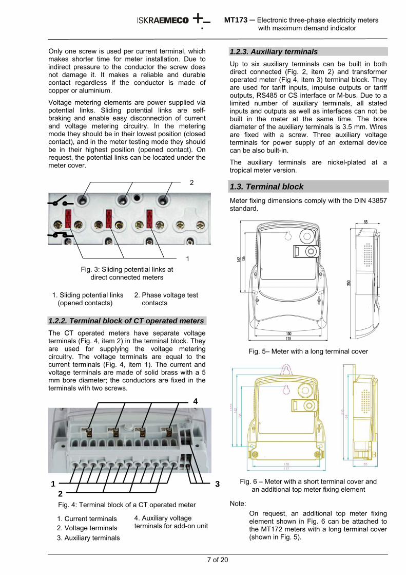
Voltage metering elements are power supplied via potential links. Sliding potential links are self-braking and enable easy disconnection of current and voltage metering circuitry. In the metering mode they should be in their lowest position (closed contact), and in the meter testing mode they should be in their highest position (opened contact). On request, the potential links can be located under the meter cover.
Fig. 3: Sliding potential links at direct connected meters
1. Sliding potential links (opened contacts)
2. Phase voltage test contacts
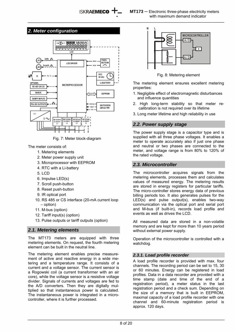
1.2.2. Terminal block of CT operated meters The CT operated meters have separate voltage terminals (Fig. 4, item 2) in the terminal block. They are used for supplying the voltage metering circuitry. The voltage terminals are equal to the current terminals (Fig. 4, item 1). The current and voltage terminals are made of solid brass with a 5 mm bore diameter; the conductors are fixed in the terminals with two screws.
Fig. 4: Terminal block of a CT operated meter
1. Current terminals 2. Voltage terminals
4. Auxiliary voltage terminals for add-on unit
3. Auxiliary terminals
1.2.3. Auxiliary terminals Up to six auxiliary terminals can be built in both direct connected (Fig. 2, item 2) and transformer operated meter (Fig 4, item 3) terminal block. They are used for tariff inputs, impulse outputs or tariff outputs, RS485 or CS interface or M-bus. Due to a limited number of auxiliary terminals, all stated inputs and outputs as well as interfaces can not be built in the meter at the same time. The bore diameter of the auxiliary terminals is 3.5 mm. Wires are fixed with a screw. Three auxiliary voltage terminals for power supply of an external device can be also built-in.
The auxiliary terminals are nickel-plated at a tropical meter version.
1.3. Terminal block Meter fixing dimensions comply with the DIN 43857 standard.
Fig. 5– Meter with a long terminal cover
Fig. 6 – Meter with a short terminal cover and an additional top meter fixing element
Note:
On request, an additional top meter fixing element shown in Fig. 6 can be attached to the MT172 meters with a long terminal cover (shown in Fig. 5).
4
12
3
2
1
8 of 20
MT173 ─ Electronic three-phase electricity meters with maximum demand indicator
2. Meter configuration
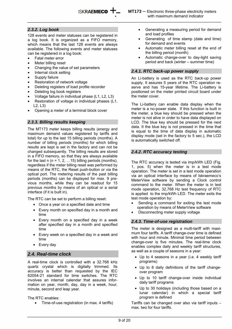
Fig. 7: Meter block-diagram The meter consists of:
1. Metering elements 2. Meter power supply unit 3. Microprocessor with EEPROM 4. RTC with a Li-battery 5. LCD 6. Impulse LED(s) 7. Scroll push-button 8. Reset push-button 9. IR optical port 10. RS 485 or CS interface (20-mA current loop – option) 11. M-bus (option) 12. Tariff input(s) (option) 13. Pulse outputs or tariff outputs (option)
2.1. Metering elements The MT173 meters are equipped with three metering elements. On request, the fourth metering element can be built in the neutral line.
The metering element enables precise measure-ment of active and reactive energy in a wide me-tering and a temperature range. It consists of a current and a voltage sensor. The current sensor is a Rogowski coil (a current transformer with an air core), while the voltage sensor is a resistive voltage divider. Signals of currents and voltages are fed to the A/D converters. Then they are digitally mul-tiplied so that instantaneous power is calculated. The instantaneous power is integrated in a micro-controller, where it is further processed.
Fig. 8: Metering element The metering element ensures excellent metering properties: 1. Negligible effect of electromagnetic disturbances and influence quantities 2. High long-term stability so that meter re-
calibration is not required over its lifetime 3. Long meter lifetime and high reliability in use 2.2. Power supply stage The power supply stage is a capacitor type and is supplied with all three phase voltages. It enables a meter to operate accurately also if just one phase and neutral or two phases are connected to the meter, and voltage range is from 80% to 120% of the rated voltage.
2.3. Microcontroller The microcontroller acquires signals from the metering elements, processes them and calculates values of measured energy. The metering results are stored in energy registers for particular tariffs. The micro-controller stores energy data of previous billing periods too. It also generates pulses for the LED(s) and pulse output(s), enables two-way communication via the optical port and serial port and M-bus (if built-in), records load profile and events as well as drives the LCD. All measured data are stored in a non-volatile memory and are kept for more than 10 years period without external power supply. Operation of the microcontroller is controlled with a watchdog.
2.3.1. Load profile recorder A load profile recorder is provided with max. four channels. The recording period can be set to 15, 30 or 60 minutes. Energy can be registered in load profiles. Data in a data recorder are provided with a time stamp (date and time of the end of a registration period), a meter status in the last registration period and a check sum. Depending on the size of a memory that is built in EEPROM, maximal capacity of a load profile recorder with one channel and 60-minute registration period is approx. 120 days.
9 of 20
MT173 ─ Electronic three-phase electricity meters with maximum demand indicator
2.3.2. Log book 128 events and meter statuses can be registered in a log book. It is organized as a FIFO memory, which means that the last 128 events are always available. The following events and meter statuses can be registered in a log book: • Fatal meter error • Meter billing reset • Changing the value of set parameters • Internal clock setting • Supply failure • Restoration of network voltage • Deleting registers of load profile recorder • Deleting log book registers • Voltage failure in individual phase (L1, L2, L3) • Restoration of voltage in individual phases (L1,
L2, L3) • Opening a meter of a terminal block cover
2.3.3. Billing results keeping The MT173 meter keeps billing results (energy and maximum demand values registered by tariffs and total) for up to the last 15 billing periods (months). A number of billing periods (months) for which billing results are kept is set in the factory and can not be changed subsequently. The billing results are stored in a FIFO memory, so that they are always available for the last n (n = 1, 2, …15) billing periods (months), regardless if the meter billing reset was performed by means of the RTC, the Reset push-button or via the optical port. The metering results of the past billing periods (months) can be displayed for max. 9 pre-vious months, while they can be readout for 15 previous months by means of an optical or a serial interface (if it is built in).
The RTC can be set to perform a billing reset: • Once a year on a specified date and time • Every month on specified day in a month and
time • Every month on a specified day in a week
after specified day in a month and specified time
• Every week on a specified day in a week and time
• Every day
2.4. Real-time clock A real-time clock is controlled with a 32.768 kHz quartz crystal which is digitally trimmed. Its accuracy is better than requested by the IEC 62054-21 standard for time switches. The RTC involves an internal calendar that assures infor-mation on year, month, day, day in a week, hour, minute, second and leap year. The RTC enables:
• Time-of-use registration (in max. 4 tariffs)
• Generating a measuring period for demand and load profiles
• Generating of time stamp (date and time) for demand and events
• Automatic meter billing reset at the end of the billing period (month)
• Automatic change-over to day-light saving period and back (winter – summer time)
2.4.1. RTC back-up power supply An Li-battery is used as the RTC back-up power supply. It assures 5 years of the RTC operation re-serve and has 15-year lifetime. The Li-battery is positioned on the meter printed circuit board under the meter cover. The Li-battery can enable data display when the meter is a no-power state. If this function is built in the meter, a blue key should be pressed when the meter is not alive in order to have data displayed on LCD. The blue key should be pressed for the next data. It the blue key is not pressed in the time that is equal to the time of data display in automatic display mode (set in the factory to 5 sec.), the LCD is automatically switched off.
2.4.2. RTC accuracy testing The RTC accuracy is tested via imp/kWh LED (Fig. 1, pos. 5) when the meter is in a test mode operation. The meter is set in a test mode operation via an optical interface by means of Iskraemeco’s MeterView software by sending a Clock control command to the meter. When the meter is in test mode operation, 32,768 Hz test frequency of RTC is applied to the imp/kWh LED. The meter exits the test mode operation by: • Sending a command for exiting the test mode
operation by means of MeterView software • Disconnecting meter supply voltage 2.4.3. Time-of-use registration The meter is designed as a multi-tariff with maxi-mum four tariffs. A tariff change-over time is defined with hour and minute. Minimal time period between change-over is five minutes. The real-time clock enables complex daily and weekly tariff structures, as well as a couple of seasons in a year:
• Up to 4 seasons in a year (i.e. 4 weekly tariff programs)
• Up to 8 daily definitions of the tariff change-over program
• Up to 10 tariff change-over inside individual daily tariff programs
• Up to 30 holidays (including those based on a lunar calendar) in which a special tariff program is defined
Tariffs can be changed over also via tariff inputs – max. two for four tariffs.
10 of 20
MT173 ─ Electronic three-phase electricity meters with maximum demand indicator
2.4.4. Maximum demand measuring The internal clock generates a measuring period for demand calculation. Demand is calculated as a mean value in the measuring period. In the MT173 meters the following measuring periods can be set: 5, 15, 30 or 60 minutes. At the end of a measuring period, the calculated demand is transferred from the current measuring period register to the register of the measuring period that was just terminated. It is compared with the value stored in the maximum demand in the billing period. If the new calculated period is greater than the value in the maximum demand register, a new demand value is entered, otherwise the old value is kept. In this way, a maximum demand is also registered at a meter billing reset. 2.4.5. Meter billing reset A meter billing reset is usually done by RTC once a month. However, any other period of a meter billing reset can also be set (see Item 2.3.3 “Billing results keeping”). Day and time of the meter billing reset can be set for any day in a month and any time during a day. At a meter billing reset the billing data for a current month are transferred from the regis-ters for a current month (a billing period) to the registers of a previous month (a billing period, while the registers of a current month (a billing period) are deleted in order to be ready for measurement in the next month (a billing period). At the same time a counter of billing resets is incremented. The meter billing reset can be performed not only by means of RTC but also by pressing the Reset push-button (see Item 2.7.4 “Manual meter billing reset”), via the IR optical port or remotely via a serial interface, if available.
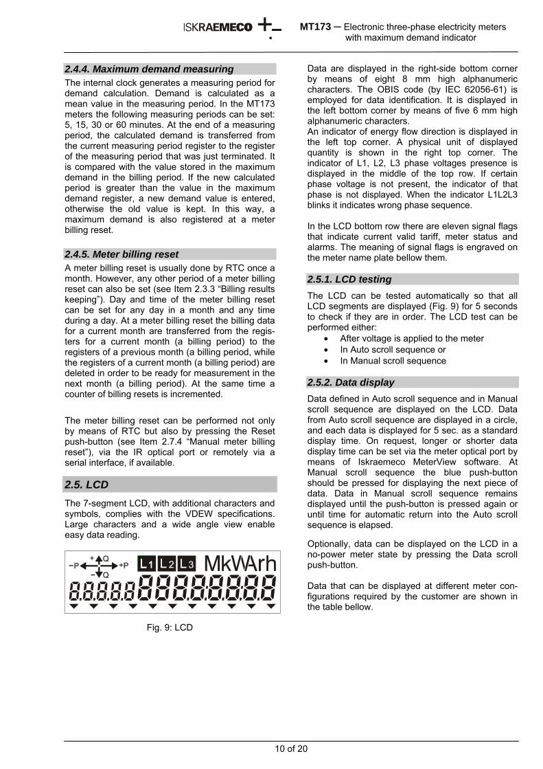
2.5. LCD The 7-segment LCD, with additional characters and symbols, complies with the VDEW specifications. Large characters and a wide angle view enable easy data reading.
Fig. 9: LCD
Data are displayed in the right-side bottom corner by means of eight 8 mm high alphanumeric characters. The OBIS code (by IEC 62056-61) is employed for data identification. It is displayed in the left bottom corner by means of five 6 mm high alphanumeric characters. An indicator of energy flow direction is displayed in the left top corner. A physical unit of displayed quantity is shown in the right top corner. The indicator of L1, L2, L3 phase voltages presence is displayed in the middle of the top row. If certain phase voltage is not present, the indicator of that phase is not displayed. When the indicator L1L2L3 blinks it indicates wrong phase sequence. In the LCD bottom row there are eleven signal flags that indicate current valid tariff, meter status and alarms. The meaning of signal flags is engraved on the meter name plate bellow them. 2.5.1. LCD testing The LCD can be tested automatically so that all LCD segments are displayed (Fig. 9) for 5 seconds to check if they are in order. The LCD test can be performed either:
• After voltage is applied to the meter • In Auto scroll sequence or • In Manual scroll sequence
2.5.2. Data display Data defined in Auto scroll sequence and in Manual scroll sequence are displayed on the LCD. Data from Auto scroll sequence are displayed in a circle, and each data is displayed for 5 sec. as a standard display time. On request, longer or shorter data display time can be set via the meter optical port by means of Iskraemeco MeterView software. At Manual scroll sequence the blue push-button should be pressed for displaying the next piece of data. Data in Manual scroll sequence remains displayed until the push-button is pressed again or until time for automatic return into the Auto scroll sequence is elapsed. Optionally, data can be displayed on the LCD in a no-power meter state by pressing the Data scroll push-button. Data that can be displayed at different meter con-figurations required by the customer are shown in the table bellow.
11 of 20
MT173 ─ Electronic three-phase electricity meters with maximum demand indicator
Energy data and demand can be displayed in data formats given in a table bellow. Data format No. of integers No. of decimal
places Energy
6.0 6 0 7.1 6 1 7.0 7 0 8.1 7 1 8.0 8 0
Maximum demand 4.3 1 3
Cumulative maximum demand 6.3 3 3
T he meters can be set into the meter test mode via their optical port by means of Iskraemeco MeterView software (SET menu) in which energy data are displayed with higher resolution, i.e. in a data format 8.3 (5 integers + 3 decimals). At the same time imp/kWh (and imp/kvarh LED if it is built-in) starts to emit pulses with pulse rate 100,000 imp/kWh (or 100,000 imp/kvarh). In this way time needed for meter accuracy testing at low load is shortened.
2.5.3. Signal flags The signal flags in the display bottom row indicate certain meter status and alarms.
The signal flags from left to right have the following functions:
No. FLAG STATUS MEANING 1 T1 Lit Active first tariff 2 T2 Lit Active second tariff 3 T3 Lit Active third tariff 4 T4 Lit Active fourth tariff 5 Not used 6 Not used 7 Not used
8 PD Lit Data display on LCD in a no-power meter state
9 FF Lit Meter fatal error
10 DRO Lit Meter data down-loading is in progress
11 SET Lit Meter in programming mode
* If the FF signal flag is displayed, the meter should be dismounted from a place of measu-rement and sent to an authorized repair shop or to the manufacturer for examination.
EDIS CODE DATA DESCRIPTION
F.F.0 Meter fatal error 0.0.0 Device address C.1.0 Meter serial number 0.9.1 Time ( data format: hh:mm:ss) 0.9.2 Date ( data format YY.MM.DD)
1.2.0 Cumulative demand active positive, total (Pcum+)
1.2.n Cumulative demand active positive, in n- tariff (n = 1, 2, 3, 4)
1.6.0 Maximum demand active positive, total (P+)
1.6.n Maximum demand active positive, in n- tariff (n = 1, 2, 3, 4)
1.8.0 Total positive active energy (A+)
1.8.n Positive active energy in n- tariff (n=1, 2, 3, 4 )
2.2.0 Cumulative demand positive negative, total (Pcum-)
2.2.n Cumulative demand active negative, in n- tariff (n = 1, 2, 3, 4)
2.6.0 Maximum demand active negative, total (P-)
2.6.n Maximum demand active negative, in n- tariff (n = 1, 2, 3, 4)
2.8.0 Total negative active energy (A-) 2.8.n Negative active energy in n- tariff (n=1,2,3,4)
3.2.0 Cumulative demand reactive positive, total (Qcum+)
3.2.n Cumulative demand reactive positive, in n- tariff (n = 1, 2, 3, 4)
3.6.0 Maximum demand reactive positive, total (Q+)
3.6.n Maximum demand reactive positive, in n- tariff (n = 1, 2, 3, 4)
3.8.0 Total positive reactive energy (R+)
3.8.n Positive reactive energy in n- tariff (n=1, 2, 3, 4 )
4.2.0 Cumulative demand reactive negative, total (Qcum-)
4.2.n Cumulative demand reactive negative, in n- tariff (n = 1, 2, 3, 4)
4.6.0 Maximum demand reactive negative, total (Q-)
4.6.n Maximum demand reactive negative, in n- tariff (n = 1, 2, 3, 4)
4.8.0 Total negative reactive energy (R-)
4.8.n Negative reactive energy in n- tariff (n=1, 2, 3, 4 )
15.2.0 Cumulative demand active absolute, total (IPkumI)
15.2.n Cumulative demand active absolute, in n- tariff (n = 1, 2, 3, 4)
15.6.0 Maximum demand active absolute, total (IPI)
15.6.n Maximum demand active absolute, in n- tariff (n = 1, 2, 3, 4)
15.8.0 Total absolute active energy |A|
15.8.n Absolute active energy in n- tariff (n=1, 2, 3, 4 )
12 of 20
MT173 ─ Electronic three-phase electricity meters with maximum demand indicator
2.6. LEDs The meters for active energy only are provided with a LED (imp/kWh). The meters for active and reactive energy are provided with two LEDs (imp/kWh and imp/kvarh). The LED(s) are used for testing the meter accuracy and indicating meter operation. If current through the meter is smaller than the meter starting current, the LEDs (or a LED) are permanently lit.
LED STATUS INDICATION
Blinks Energy is registered. The pulse rate is proportional to the consumed power.
Lit Volgase applied to the meter, but load current is lower than the meter starting current.
Imp/kWh Imp/kvarh
Not lit Voltage not applied to the meter.
The emitted pulse rate depends on the meter version.
Meter version Imax Meter constant
Direct connected 120 A 500 imp/kWh
(500 imp/kvarh)
Direct connected 85A 1,000 imp/kWh
(1,000 imp/kvarh)
CT operated 6 A 10,000 imp/kWh
(10,000 imp/kvarh)
Imp/kWh LED has the additional function. In the test mode operation for RTC accuracy is blinks with frequency that is equal to the test frequency on RTC, i.e. 32,768 HZ (see Item 2.4.2 “Testing RTC accuracy”. 2.7. Push-buttons Two pushbuttons are built in the meter cover. .
1 – Data scroll pushbutton 2 – Reset pushbutton 3 – Cover of Reset pushbutton
Fig. 10: Pushbuttons on the meter cover
• RESET – an orange pushbutton under the cover that is fixed to the meter cover.
Available sealing that does not depend on the meter cover. Its primary function is manual billing reset of the meter.
• DATA SCROLL – the blue pushbutton that
is always available. Its primary function is data display on request.
Depending on how long the pushbutton was pressed and the combination of pressing, the pushbuttons enable:
• Selection of the meter operation mode, • Testing of display, • Listing of metering results and setting of
RTC time and date, • Manual billing reset of the meter
At the orange pushbutton the length of pressing does not influence in its function, while at the blue pushbutton there are three lengths of pressing:
a. Short – less than 2 sec. – the next data in the menu is displayed.
b. Long – pressing longer than 2 sec. and shorter than 5 sec. – a submenu or a function whose name is displayed is selected.
c. Prolonged – the length of pressing is more than 5 sec. – the meter is returned for one level of operation (e.g. on the third level it is necessary to press the blue pushbutton three times and always keep it pressed for more than 5 sec. in order to come to an automatic data display mode).
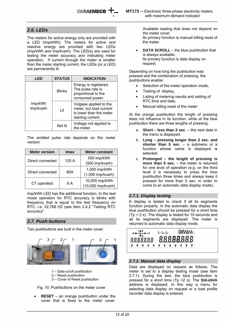
2.7.1. Display testing A display is tested to check if all its segments function properly. In the automatic data display the blue pushbutton should be pressed for a short time (Tp < 2 s). The display is tested for 10 seconds and all its segments are displayed. The meter is returned to automatic data display mode.
2.7.2. Manual data display Data are displayed on request as follows. The meter is set to a display testing mode (see Item 2.7.1). During the test, the blue pushbutton is pressed for a short time (Tp <2 s). The Std-dAtA address is displayed. In this way a menu for selecting data display on request or a load profile recorder data display is entered.
3 2 1 3 1
13 of 20
MT173 ─ Electronic three-phase electricity meters with maximum demand indicator
In order to enter the data display menu on request, the blue pushbutton should be pressed for a long time (2 s < Tp < 5 s). The first data is displayed from the list of data on request. For a display of the following data from a list of data on request, the blue pushbutton should be pressed for a short time. The exit from a data display on request mode is performed by prolonged pressing the blue pushbutton (Tp> 5 s).
2.7.3. Manual meter billing reset For a manual meter billing reset with which the meter is prepared for a new billing period, the cover of the orange pushbutton should be unsealed first. The orange pushbutton should be pressed when the meter is in the automatic data display mode. In case of the meter billing reset, the billing data are transferred from the registers for a current month to the registers for a previous month, the registers for a current month are deleted, and the counter of performed billing resets is incremented by one. In order to prevent misusing of the Reset pushbutton after the meter billing reset, the orange pushbutton is disabled for one metering period for demand. If the orange pushbutton is pressed in time that is shorter than the metering period for demand, the meter billing reset will not be performed. After manual meter reset, the orange pushbutton cover should be closed and sealed. On request, the function of manual meter billing reset is disabled. 2.8. Communication channels Built-in communication channels enable:
Billing data readout Load profiles readout Log book registers readout Meter parameters readout Meter parameters setting
The meters can be equipped with the following communication channels:
Optical interface (always built-in) RS485 or CS interface (on request) M-bus (on request)
The communication with the meter is shown on LCD by indicating the DRO flag.
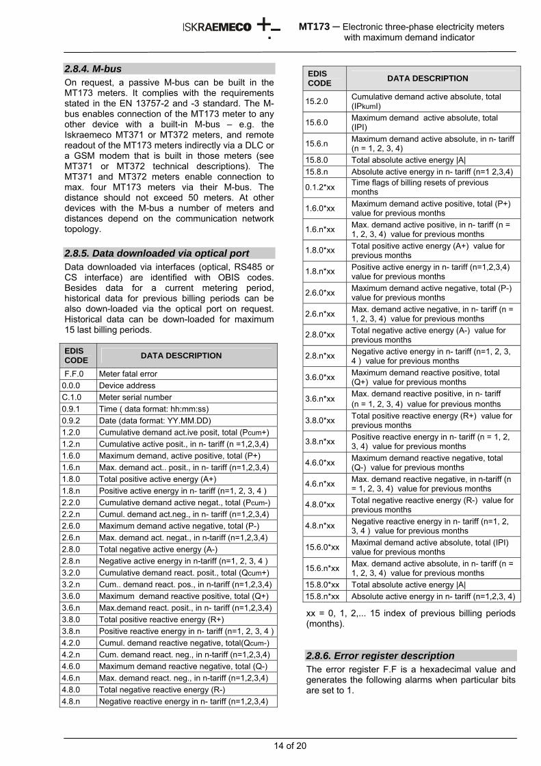
2.8.1. Optical interface In the right upper angle of the meter there is an optical interface that complies with the IEC 62056-21 standard. It is intended for local setting of the meter parameters and data readout.
Fig. 11: Optical interface
The communication protocol is IEC 62056-21, mode C. Communication mode is serial asyn-chronous. All data transmission rates from 300 bit/s to 9.600 bit/s are available. If data transmission rate of the used optical probe is less than 9.600 bit/s, max. data transmission rate is equal to max. data transmission rate of the optical probe. The wave length of the optical interface light is 660 nm, luminous intensity in active state is min. 1 mW/sr.
2.8.2. RS485 interface On request, the RS485 interface can be built in the MT173 meters. It enables remote readout and setting of meter parameters. The RS485 interface enables connection of 31 pcs. of MT173 meters to one communicator with a built-in RS485 interface, e.g. Iskraemeco P2CC. Master-slave architecture is used. The communication is a master device, and the MT173 meters are slave devices. Max. distance between the meters and the communicator is 1,200 meters. At two-way com-munication via the RS485 interface the IEC 62056-21, mode C protocol is used. Data transmission rate is 9.600 bit/s.
2.8.3. CS interface On request, CS (20-mA current loop) interface in compliance with the DIN 66348 standard can also be built in the MT173 meters as an alternative for remote readout and meter setting.
A number of meters that can be built in one current loop depends of their distance from the communi-cator. The master – slave architecture is used. The communicator (e.g. Iskraemeco P2CBT) is a master device, and the MT173 meters are slave devices. In one current loop, max. 6 meters can be built in if the distance from the communicator is not large. If only one meter is built in, max. distance to the communicator can be 5,000 meters, while in case of four meters this distance is 1,200 meters. At two-way communication via the CS interface the IEC 62056-21, mode C protocol is used. The data trans-mission rate is 2.400 bit/sec.
14 of 20
MT173 ─ Electronic three-phase electricity meters with maximum demand indicator
2.8.4. M-bus On request, a passive M-bus can be built in the MT173 meters. It complies with the requirements stated in the EN 13757-2 and -3 standard. The M-bus enables connection of the MT173 meter to any other device with a built-in M-bus – e.g. the Iskraemeco MT371 or MT372 meters, and remote readout of the MT173 meters indirectly via a DLC or a GSM modem that is built in those meters (see MT371 or MT372 technical descriptions). The MT371 and MT372 meters enable connection to max. four MT173 meters via their M-bus. The distance should not exceed 50 meters. At other devices with the M-bus a number of meters and distances depend on the communication network topology. 2.8.5. Data downloaded via optical port Data downloaded via interfaces (optical, RS485 or CS interface) are identified with OBIS codes. Besides data for a current metering period, historical data for previous billing periods can be also down-loaded via the optical port on request. Historical data can be down-loaded for maximum 15 last billing periods.
xx = 0, 1, 2,... 15 index of previous billing periods (months). 2.8.6. Error register description The error register F.F is a hexadecimal value and generates the following alarms when particular bits are set to 1.
EDIS CODE DATA DESCRIPTION
15.2.0 Cumulative demand active absolute, total (IPkumI)
15.6.0 Maximum demand active absolute, total (IPI)
15.6.n Maximum demand active absolute, in n- tariff (n = 1, 2, 3, 4)
15.8.0 Total absolute active energy |A| 15.8.n Absolute active energy in n- tariff (n=1 2,3,4)
0.1.2*xx Time flags of billing resets of previous months
1.6.0*xx Maximum demand active positive, total (P+) value for previous months
1.6.n*xx Max. demand active positive, in n- tariff (n = 1, 2, 3, 4) value for previous months
1.8.0*xx Total positive active energy (A+) value for previous months
1.8.n*xx Positive active energy in n- tariff (n=1,2,3,4) value for previous months
2.6.0*xx Maximum demand active negative, total (P-) value for previous months
2.6.n*xx Max. demand active negative, in n- tariff (n = 1, 2, 3, 4) value for previous months
2.8.0*xx Total negative active energy (A-) value for previous months
2.8.n*xx Negative active energy in n- tariff (n=1, 2, 3, 4 ) value for previous months
3.6.0*xx Maximum demand reactive positive, total (Q+) value for previous months
3.6.n*xx Max. demand reactive positive, in n- tariff (n = 1, 2, 3, 4) value for previous months
3.8.0*xx Total positive reactive energy (R+) value for previous months
3.8.n*xx Positive reactive energy in n- tariff (n = 1, 2, 3, 4) value for previous months
4.6.0*xx Maximum demand reactive negative, total (Q-) value for previous months
4.6.n*xx Max. demand reactive negative, in n-tariff (n = 1, 2, 3, 4) value for previous months
4.8.0*xx Total negative reactive energy (R-) value for previous months
4.8.n*xx Negative reactive energy in n- tariff (n=1, 2, 3, 4 ) value for previous months
15.6.0*xx Maximal demand active absolute, total (IPI) value for previous months
15.6.n*xx Max. demand active absolute, in n- tariff (n = 1, 2, 3, 4) value for previous months
15.8.0*xx Total absolute active energy |A| 15.8.n*xx Absolute active energy in n- tariff (n=1,2,3, 4)
EDIS CODE DATA DESCRIPTION
F.F.0 Meter fatal error 0.0.0 Device address C.1.0 Meter serial number 0.9.1 Time ( data format: hh:mm:ss) 0.9.2 Date (data format: YY.MM.DD) 1.2.0 Cumulative demand act.ive posit, total (Pcum+) 1.2.n Cumulative active posit., in n- tariff (n =1,2,3,4) 1.6.0 Maximum demand, active positive, total (P+) 1.6.n Max. demand act.. posit., in n- tariff (n=1,2,3,4) 1.8.0 Total positive active energy (A+) 1.8.n Positive active energy in n- tariff (n=1, 2, 3, 4 ) 2.2.0 Cumulative demand active negat., total (Pcum-) 2.2.n Cumul. demand act.neg., in n- tariff (n=1,2,3,4) 2.6.0 Maximum demand active negative, total (P-) 2.6.n Max. demand act. negat., in n-tariff (n=1,2,3,4) 2.8.0 Total negative active energy (A-) 2.8.n Negative active energy in n-tariff (n=1, 2, 3, 4 ) 3.2.0 Cumulative demand react. posit., total (Qcum+) 3.2.n Cum.. demand react. pos., in n-tariff (n=1,2,3,4) 3.6.0 Maximum demand reactive positive, total (Q+) 3.6.n Max.demand react. posit., in n- tariff (n=1,2,3,4) 3.8.0 Total positive reactive energy (R+) 3.8.n Positive reactive energy in n- tariff (n=1, 2, 3, 4 )4.2.0 Cumul. demand reactive negative, total(Qcum-) 4.2.n Cum. demand react. neg., in n-tariff (n=1,2,3,4) 4.6.0 Maximum demand reactive negative, total (Q-) 4.6.n Max. demand react. neg., in n-tariff (n=1,2,3,4) 4.8.0 Total negative reactive energy (R-) 4.8.n Negative reactive energy in n- tariff (n=1,2,3,4)
15 of 20
MT173 ─ Electronic three-phase electricity meters with maximum demand indicator
Bit Error Description 0 Check sum error in energy registers in
EEPROM 1 Check sum error of meter parameters in
EEPROM 2 Check sum error of meter parameters in RAM 3 Check sum error of program code 4 False tariff table 5 Not implemented 6 Not implemented 7 Not implemented
2.8.7. Communication protocol The communication protocol is IEC 62056-21 mode C. The communication is asynchronous half-duplex.
Data format: 1 start bit, 7 data bits, 1 parity bit, 1 stop bit
The entire data block is protected by a control mark in compliance with the DIN 66219 standard.
After receiving the calling telegram at a 300 baud data transmission rate,
/ ? Device address ! CR LF or / ? ! CR LF
the meter reveals its identification at a 300 baud data transmission rate:
/ I S K 5 M T173 – “Program version”
The meter address refers to the contents of the 0.0.0 or 0.0.1 registers. Then the meter waits for 2 sec. so that the proposed data transmission rate is confirmed:
ACK 0 5 0 CR LF.
If the proposed baud rate is confirmed, communication at a 9,600 baud rate follows; if it is not confirmed, communication at 300 baud continues. The meter transmits the data telegram:
STX Data ! CR LF ETX BCC
where STX: stands for the start of a text; Data: refers to codes and data
! CR LF: stands for the end of data ETX: stands for the end of a text
BCC: stands for Block Check Character – parity check
2.9. Inputs and outputs Inputs and outputs are built in the MT173 meters on request. They are deduced to auxiliary terminals on the right side of a terminal block. The following inputs and outputs are available:
• Impulse output • Tariff output
• Tariff input Not all combinations of inputs and outputs are possible (only impulse output or tariff output – not both at the same time). A number of auxiliary terminals in a terminal block – six auxiliary terminals – are available when selecting auxiliary inputs and outputs, and an interface and a conductor.
2.9.1. Tariff input In the MT173 meters one (two-tariff meters) or two tariff inputs (three or four-tariff meters) for external tariff changeover can be built in. A customer can specify at which voltage combination at outputs a certain tariff is valid. The customer can also specify if a tariff input has a ground deduced to the auxiliary terminal or it has a common ground with a meter. A tariff input is controlled with ac phase voltage Un. It is valid that: Voltage is present at the input if U ≥ 0,8 Un; Voltage is not present at input if U ≤ 0,2 Un.
2.9.2. Impulse output In the MT173 meters one (active energy meters for one energy flow direction, or absolute meters) or two impulse outputs (active and reactive energy meter for one energy flow direction or active energy meters for two energy flow directions) can be built in. Impulse output is passive or it complies with the requirements stated in the IEC 62053-32 standard, class A (S0 in compliance with DIN 43864). Impulse constant is equal to the half of meter constant, impulse width is 30 ms. However, a smaller impulse constant or a larger impulse length can be set on request. If different impulse length and impulse constants are required, it is necessary to prevent lapping of impulses at maximum load. Impulses can be transferred at 0.5 m distance. On request, the impulse output can be performed as an optomos relay with a make contact that can changeover 25 W (100 mA, 250 V). In this case data transmission at a distance of 1 km is made possible.
2.9.3. Tariff output In the MT173 meters one or two tariff outputs can be built for controlling an external device by a tariff program that is stored in the meter instead of an impulse output. A tariff output is performed as an optomos relay with a make contact that can switchover 25 W (100 mA, 250 V).
16 of 20
MT173 ─ Electronic three-phase electricity meters with maximum demand indicator
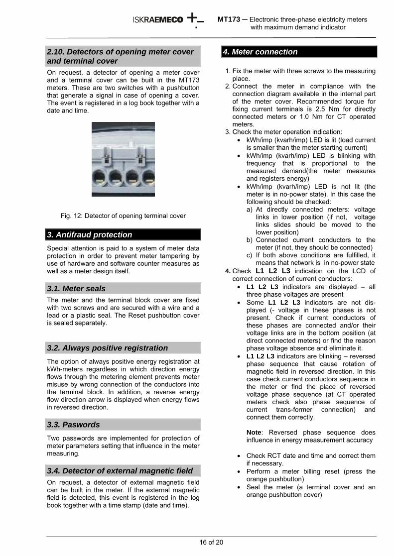
2.10. Detectors of opening meter cover and terminal cover On request, a detector of opening a meter cover and a terminal cover can be built in the MT173 meters. These are two switches with a pushbutton that generate a signal in case of opening a cover. The event is registered in a log book together with a date and time.
Fig. 12: Detector of opening terminal cover 3. Antifraud protection Special attention is paid to a system of meter data protection in order to prevent meter tampering by use of hardware and software counter measures as well as a meter design itself. 3.1. Meter seals The meter and the terminal block cover are fixed with two screws and are secured with a wire and a lead or a plastic seal. The Reset pushbutton cover is sealed separately. 3.2. Always positive registration The option of always positive energy registration at kWh-meters regardless in which direction energy flows through the metering element prevents meter misuse by wrong connection of the conductors into the terminal block. In addition, a reverse energy flow direction arrow is displayed when energy flows in reversed direction. 3.3. Paswords Two passwords are implemented for protection of meter parameters setting that influence in the meter measuring. 3.4. Detector of external magnetic field On request, a detector of external magnetic field can be built in the meter. If the external magnetic field is detected, this event is registered in the log book together with a time stamp (date and time).
4. Meter connection 1. Fix the meter with three screws to the measuring
place. 2. Connect the meter in compliance with the
connection diagram available in the internal part of the meter cover. Recommended torque for fixing current terminals is 2.5 Nm for directly connected meters or 1.0 Nm for CT operated meters.
3. Check the meter operation indication: • kWh/imp (kvarh/imp) LED is lit (load current
is smaller than the meter starting current) • kWh/imp (kvarh/imp) LED is blinking with
frequency that is proportional to the measured demand(the meter measures and registers energy)
• kWh/imp (kvarh/imp) LED is not lit (the meter is in no-power state). In this case the following should be checked: a) At directly connected meters: voltage
links in lower position (if not, voltage links slides should be moved to the lower position)
b) Connected current conductors to the meter (if not, they should be connected)
c) If both above conditions are fulfilled, it means that network is in no-power state
4. Check L1 L2 L3 indication on the LCD of correct connection of current conductors:
• L1 L2 L3 indicators are displayed – all three phase voltages are present
• Some L1 L2 L3 indicators are not dis-played (- voltage in these phases is not present. Check if current conductors of these phases are connected and/or their voltage links are in the bottom position (at direct connected meters) or find the reason phase voltage absence and eliminate it.
• L1 L2 L3 indicators are blinking – reversed phase sequence that cause rotation of magnetic field in reversed direction. In this case check current conductors sequence in the meter or find the place of reversed voltage phase sequence (at CT operated meters check also phase sequence of current trans-former connection) and connect them correctly.
Note: Reversed phase sequence does influence in energy measurement accuracy
• Check RCT date and time and correct them if necessary.
• Perform a meter billing reset (press the orange pushbutton)
• Seal the meter (a terminal cover and an orange pushbutton cover)
17 of 20
MT173 ─ Electronic three-phase electricity meters with maximum demand indicator
5. Tools The following tool is used:
• For service meter programming and data download: 1. MeterView (Iskraemeco software) 2. Optical Probe 3. PC: a desktop, a laptop
The tool is intended for the operators who service or reprogram the meters in the laboratory or in the field.
• For data downloading and meters programming in the field 1. MeterRead (Iskraemeco software) for all
type of palmtop PCs operating in the Windows CE environment
2. Optical probe 6. Meter maintenance The meter is designed and manufactured in such a way that no maintenance is required in the entire meter lifetime. Measuring stability assures that no recalibration is required. If a battery is built into the meter, its capacity is sufficient to backup all functions for the entire meter lifetime.
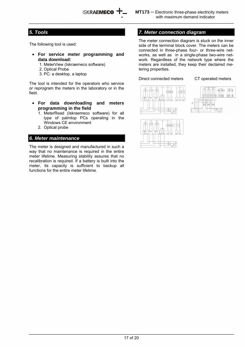
7. Meter connection diagram The meter connection diagram is stuck on the inner side of the terminal block cover. The meters can be connected in three-phase four- or three-wire net-works, as well as in a single-phase two-wire net-work. Regardless of the network type where the meters are installed, they keep their declaired me-tering properties. Direct connected meters CT operated meters
18 of 20
MT173 ─ Electronic three-phase electricity meters with maximum demand indicator
8. Technical data GENERAL METER MEASURING PROPERTIES Accuracy class for active energy
A or B (EN 50470-3) or 2 or 1 ( IEC 62053-21)
Accuracy class for reactive ener. 3 or 2 ( IEC 62053-23)
Basic current In Dir. connected meter: 5 A CT operated meter: 1 A
Max. current Imax Dir. connected meter: 85 A or 120 A CT operated meter: 5 (6) A
Min. current Imin Dir. connected meter: 250 mA CT operated meter : 20 mA
Starting current <0,005 Ib at cos ϕ = 1, for class 2 <0,004 Ib at cos ϕ = 1,for class 1
Thermal current 1,2 Imax Short-circuit current
30 Imax
Rated voltage 3x230/400 V, 3x400 V, 230 V (other voltage on request)
Voltage range 0,8 Un ... 1,15 Un Rated frequency 50 Hz or 60 Hz Meter constant (per LED)
500 imp/kWh at Imax = 120 A 500 imp/ kvarh at Imax = 120 A 1.000 imp/kWh at Imax = 85 A 1.000 imp/ kvarh at Imax = 85 A 10.000 imp/kWh at Imax = 5 A 10.000 imp/kvarh at Imax = 5 A
Operating temp. range (-40°C) -25°C ... +60°C
Extended temp. range -40°C ... +70°C
Storing temperature -40°C ... +80°C
Voltage circuit burden < 2W / 10VA
Self-consumption of current circuit
< 0,16 VA (irrespective of rated current nazivni In )
RTC Time base Quartz crystal 32 kHz Long-term accuracy of RTC (at 25°C)
Better than specified in IEC 62054-21
Back-up power supply
5 years Li-battery power supply source)
LOAD PROFILE RECORDER No. of channels Max. 4 OPTICAL INTERFACE Optical interface IEC 62056-21 (IEC 61107) Protocol IEC 62056-21 (IEC 61107) Mode C Data ident. Code. OBIS (IEC 62056-61) Data transmission rate
9.600 bit/s (limited data transmission rate of optical probe))
M-bus (option) Standard EN 13757-2 and EN 13757-3
Data transmission rate max. 2.400 bit/s
Distance Depends on network topology
RS485 INTERFACE (option) Protocol IEC 62056-21 (IEC 61107) Mode C Ident. data code. OBIS (IEC 62056-61) Data transmission rate 9.600 bit/s
Loop length 1.200 m No. of meter in a loop
max. 31
CS INTERFACE (20 mA current loop –option) Protocol IEC 62056-21 (IEC 61107) Mode C Ident. data code. OBIS (IEC 62056-61) Data transmission rate 2.400 bit/s
Loop length Depending ona number of meters in a loop
No. of meters in a loop
max. 6
OUTPUTS Impulse output
1 or 2 IEC 62053-31 class A (S0 in compl. With DIN 43864) or Optomos relay with make contact.
Tariff output Optomos relay with make contact. (option instead of of impulse output)
INPUTS Tariff inputs 1 or 2 (control voltage 230 V) METER RESISTANCE TO ELECTROMAGNETIC DISTURBANCES Dielectric strength
4 kV, 50 Hz, 1 min Electrostatic discharge 15 kV ( IEC 61000 - 4 - 2 )
High-frequency electromagnetic field
10 V/m ( IEC 61000 - 4 – 3 )
Fast transients (burst) 4 kV ( IEC 61000 - 4 - 4 )
Impulse voltage
12kV, 1,2/50 µs ( IEC 62053-21 in IEC 62052-11) –to main circuits 6 kV, 1,2/50 µs ( IEC 62053-21 i IEC 62052-11) – to auxiliary circuits
DIMENSIONS AND MASS Meters with long terminal cover: Dimensions (w x h x l)
178 x 250 x 86 mm
Meters with short terminal cover: Dimensions (w x h x l)
162 x 178 x 55 mm
Mass 1,0 kg COMBUSTIBILIY OF HOUSING Class V0 (Standard UL 94) TORQUE FOR TERMINAL SCREWS Direct-connected meters
2.5 Nm
Transform. meters
1.0 Nm
19 of 20
MT173 ─ Electronic three-phase electricity meters with maximum demand indicator
9. Meter type designation
MT173-D1A41R51-G22-M3K03Z M Electronic meter T Three-phase three-element meter 173 Time-of-use meter with maximum
demand indicator and RTC - D1 Terminal block for Imax=85 A (DIN
43857) D2 Terminal block for Imax=120 A T1 Transformer terminal block for
Imax=5 A A4 Active energy measurement,
accuracy class 1 A5 Active energy measurement,
accuracy class 2 1 Energy measurement in one
direction 2 Energy measurement in two
directions 4 Measurement of absolute energy
value R5 Reactive energy measurement,
accuracy class 2 R6 Reactive energy measurement ,
accuracy.3 1 Energy measurement in one
direction 2 Energy measurement in two
directions - V Tariff input n No. of tariff inputs (n = 1, 2) 1 Resistor tariff output for 230 V G Impulse output (class A or S0) n No. of impulse outputs (n=1, 2) 2 Transistor output L Optomos relay of impulse or tariff
output n No. of optomos outputs (n=1, 2) 1 Make contacts - M RTC 3 Back-up power supply Li-battery K Communication channel 0 Optical interface (IEC 62056-21) 1 CS interface (option) 3 RS485 interface (option) b M-bus (option) Z Load profile register (option)
20 of 20
MT173 ─ Electronic three-phase electricity meters with maximum demand indicator
Owing to periodically improvements of our products the supplied products can differ in some details from data stated in this technical description.
Iskraemeco d.d., Energy Measurement and Management 4000 Kranj, Savska loka 4, Slovenia Telephone (+386 4) 206 40 00, Fax: (+386 4) 206 43 76 http://www.iskraemeco.si, E-mail: [email protected] Published: Iskraemeco, Marketing, Data subjected to alteration without notice. MT173_TD_Eng.doc