Embed Size (px)
Citation preview
June 2005
NASA/CR-2005-213760
Energy Finite Element Analysis for
Computing the High Frequency Vibration of the
Aluminum Testbed Cylinder and Correlating the
Results to Test Data
Nickolas Vlahopoulos
University of Michigan, Ann Arbor, Michigan
https://ntrs.nasa.gov/search.jsp?R=20050160477 2018-06-02T03:36:13+00:00Z
The NASA STI Program Office . . . in Profile
Since its founding, NASA has been dedicated to the
advancement of aeronautics and space science. The
NASA Scientific and Technical Information (STI)
Program Office plays a key part in helping NASA
maintain this important role.
The NASA STI Program Office is operated by
Langley Research Center, the lead center for NASA’s
scientific and technical information. The NASA STI
Program Office provides access to the NASA STI
Database, the largest collection of aeronautical and
space science STI in the world. The Program Office is
also NASA’s institutional mechanism for
disseminating the results of its research and
development activities. These results are published by
NASA in the NASA STI Report Series, which
includes the following report types:
• TECHNICAL PUBLICATION. Reports of
completed research or a major significant phase
of research that present the results of NASA
programs and include extensive data or
theoretical analysis. Includes compilations of
significant scientific and technical data and
information deemed to be of continuing
reference value. NASA counterpart of peer-
reviewed formal professional papers, but having
less stringent limitations on manuscript length
and extent of graphic presentations.
• TECHNICAL MEMORANDUM. Scientific
and technical findings that are preliminary or of
specialized interest, e.g., quick release reports,
working papers, and bibliographies that contain
minimal annotation. Does not contain extensive
analysis.
• CONTRACTOR REPORT. Scientific and
technical findings by NASA-sponsored
contractors and grantees.
• CONFERENCE PUBLICATION. Collected
papers from scientific and technical
conferences, symposia, seminars, or other
meetings sponsored or co-sponsored by NASA.
• SPECIAL PUBLICATION. Scientific,
technical, or historical information from NASA
programs, projects, and missions, often
concerned with subjects having substantial
public interest.
• TECHNICAL TRANSLATION. English-
language translations of foreign scientific and
technical material pertinent to NASA’s mission.
Specialized services that complement the STI
Program Office’s diverse offerings include creating
custom thesauri, building customized databases,
organizing and publishing research results ... even
providing videos.
For more information about the NASA STI Program
Office, see the following:
• Access the NASA STI Program Home Page at
http://www.sti.nasa.gov
• E-mail your question via the Internet to
• Fax your question to the NASA STI Help Desk
at (301) 621-0134
• Phone the NASA STI Help Desk at
(301) 621-0390
• Write to:
NASA STI Help Desk
NASA Center for AeroSpace Information
7121 Standard Drive
Hanover, MD 21076-1320
National Aeronautics and
Space Administration
Langley Research Center Prepared for Langley Research Center
Hampton, Virginia 23681-2199 under Cooperative Agreement NCC1-03021
June 2005
NASA/CR-2005-213760
Energy Finite Element Analysis for
Computing the High Frequency Vibration of the
Aluminum Testbed Cylinder and Correlating the
Results to Test Data
Nickolas Vlahopoulos
University of Michigan, Ann Arbor, Michigan

Available from:
NASA Center for AeroSpace Information (CASI) National Technical Information Service (NTIS)
7121 Standard Drive 5285 Port Royal Road
Hanover, MD 21076-1320 Springfield, VA 22161-2171
(301) 621-0390 (703) 605-6000
1
I. INTRODUCTION
The Energy Finite Element Analysis (EFEA) is a finite element based computational method for high frequency vibration and acoustic analysis [1-7]. The EFEA solves with finite elements governing differential equations for energy variables. These equations are developed from wave equations. Recently, an EFEA method for computing high frequency vibration of structures either in vacuum or in contact with a dense fluid has been presented [2-4]. The presence of fluid loading has been considered through added mass and radiation damping. The EFEA developments were validated by comparing EFEA results to solutions obtained by very dense conventional finite element models and solutions from classical techniques such as statistical energy analysis (SEA) [8] and the modal decomposition method for bodies of revolution. EFEA results have also been compared favorably with test data for the vibration and the radiated noise generated by a large scale submersible vehicle.
The primary variable in EFEA is defined as the time averaged over a period and space averaged over a wavelength energy density. A joint matrix computed from the power transmission coefficients is utilized for coupling the energy density variables across any discontinuities, such as change of plate thickness, plate/stiffener junctions etc. When considering the high frequency vibration of a periodically stiffened plate or cylinder, the flexural wavelength is smaller than the interval length between two periodic stiffeners, therefore the stiffener stiffness can not be smeared by computing an equivalent rigidity for the plate or cylinder [11]. The periodic stiffeners must be regarded as coupling components between periodic units. In this paper, Periodic Structure (PS) theory is utilized for computing the coupling joint matrix and for accounting for the periodicity characteristics.
A structure is considered as a periodic structure when it is composed by a number of identical units connected in a regular pattern. The propagation constant, which relates the wave amplitudes of two points at adjacent units separated by the periodic distance, is used to simulate the characteristics of periodic structure. SenGupta [9] presented an overview of application of periodic structure theory in the analysis of dynamic responses of periodic structures. Mead [10] outlined systemic methods for analyzing and for predicting the free and forced wave motion in continuous and periodic structures. A formulation for computing the propagation constants of a cylindrical shell with periodically axial stringers or circumferential stiffeners is presented by Mead and Bardell in Refs. [12] and [13], respectively.
In this work, the wave transmission of a cylindrical shell stiffened by both the periodically axial stringers and the periodically circumferential stiffeners are considered. The basic periodic unit consists of a single bay of the cylindrical shell with a ring stiffener at each axial end and a stringer at each circumferential end. A hybrid method combining PS theory with the EFEA is used to solve it. The joint matrices of the EFEA formulation at stiffeners’ locations are calculated from the energy ratio between two adjacent periodic units based on the following procedure. A method same to that in Refs [10] and [13] is employed. The rotational inertia effects of the stiffeners are ignored when computing the propagation constants for the axially stiffened cylinder and the circumferentially stiffened cylinder. All the equations and related derivations corresponding to the axial stringers are presented in this report. Similar procedures and derivations can be used for the ring stiffeners. The flexural energy ratio between two adjacent periodic units is evaluated from the attenuation constants which are defined as the real part of the
2
propagation constants. An iterative algorithm [15] is employed for deriving the power transfer coefficients from the energy ratio between two adjacent periodic units. The calculated power transfer coefficients account for the periodicity characteristics and are utilized in computing the joint matrices of the EFEA formulation. The energy density distribution over the entire periodic structure is computed by the EFEA model which includes the periodicity effects through the formulation of the joint matrices. In order to validate the new development, the vibration of the NASA aluminum testbed cylinder subjected to shaker excitations are analyzed and compared with test results.
II. OVERVIEW OF EFEA FORMULATION
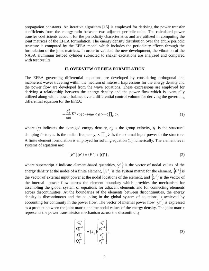
The EFEA governing differential equations are developed by considering orthogonal and incoherent waves traveling within the medium of interest. Expressions for the energy density and the power flow are developed from the wave equations. These expressions are employed for deriving a relationship between the energy density and the power flow which is eventually utilized along with a power balance over a differential control volume for deriving the governing differential equation for the EFEA:
>∏>=<<+><∇− in2
2
eηωeηω
cg , (1)
where e indicates the averaged energy density, gc is the group velocity, η is the structural
damping factor, ω is the radian frequency, >∏< in is the external input power to the structure.
A finite element formulation is employed for solving equation (1) numerically. The element level systems of equation are:
}{}{}]{[ eeee QFeK += , (2)
where superscript e indicate element-based quantities, { }ee is the vector of nodal values of the
energy density at the nodes of a finite element, [ ]eK is the system matrix for the element, { }eF is
the vector of external input power at the nodal locations of the element, and { }eQ is the vector of the internal power flow across the element boundary which provides the mechanism for assembling the global system of equations for adjacent elements and for connecting elements across discontinuities. At the boundaries of the elements between discontinuities, the energy density is discontinuous and the coupling in the global system of equations is achieved by accounting for continuity in the power flow. The vector of internal power flow { }eQ is expressed as a product between the joint matrix and the nodal values of the energy density. The joint matrix represents the power transmission mechanism across the discontinuity
=
+
+
+
+
1
1
1
1
][
mj
mj
ni
ni
ij
mj
mj
ni
ni
e
e
e
e
J
Q
Q
Q
Q
, (3)
3
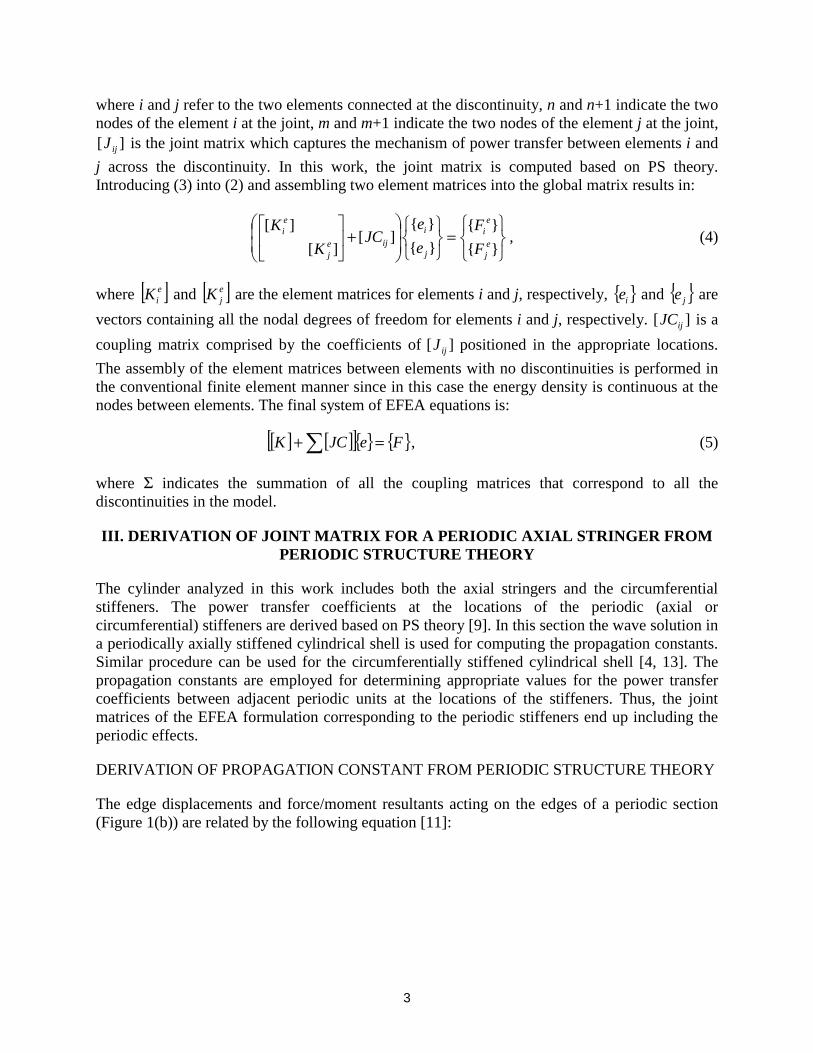
where i and j refer to the two elements connected at the discontinuity, n and n+1 indicate the two nodes of the element i at the joint, m and m+1 indicate the two nodes of the element j at the joint,
][ ijJ is the joint matrix which captures the mechanism of power transfer between elements i and
j across the discontinuity. In this work, the joint matrix is computed based on PS theory. Introducing (3) into (2) and assembling two element matrices into the global matrix results in:
=
+
}{
}{
}{
}{][
][
][ej
ei
j
i
ijej
ei
F
F
e
eJC
K
K, (4)
where [ ]eiK and [ ]e
jK are the element matrices for elements i and j, respectively, { }ie and { }je are
vectors containing all the nodal degrees of freedom for elements i and j, respectively. ][ ijJC is a
coupling matrix comprised by the coefficients of ][ ijJ positioned in the appropriate locations.
The assembly of the element matrices between elements with no discontinuities is performed in the conventional finite element manner since in this case the energy density is continuous at the nodes between elements. The final system of EFEA equations is:
[ ] [ ][ ]{ } { }FeJCK =+∑ , (5)
where Σ indicates the summation of all the coupling matrices that correspond to all the discontinuities in the model.
III. DERIVATION OF JOINT MATRIX FOR A PERIODIC AXIAL STRINGER FROM PERIODIC STRUCTURE THEORY
The cylinder analyzed in this work includes both the axial stringers and the circumferential stiffeners. The power transfer coefficients at the locations of the periodic (axial or circumferential) stiffeners are derived based on PS theory [9]. In this section the wave solution in a periodically axially stiffened cylindrical shell is used for computing the propagation constants. Similar procedure can be used for the circumferentially stiffened cylindrical shell [4, 13]. The propagation constants are employed for determining appropriate values for the power transfer coefficients between adjacent periodic units at the locations of the stiffeners. Thus, the joint matrices of the EFEA formulation corresponding to the periodic stiffeners end up including the periodic effects.
DERIVATION OF PROPAGATION CONSTANT FROM PERIODIC STRUCTURE THEORY
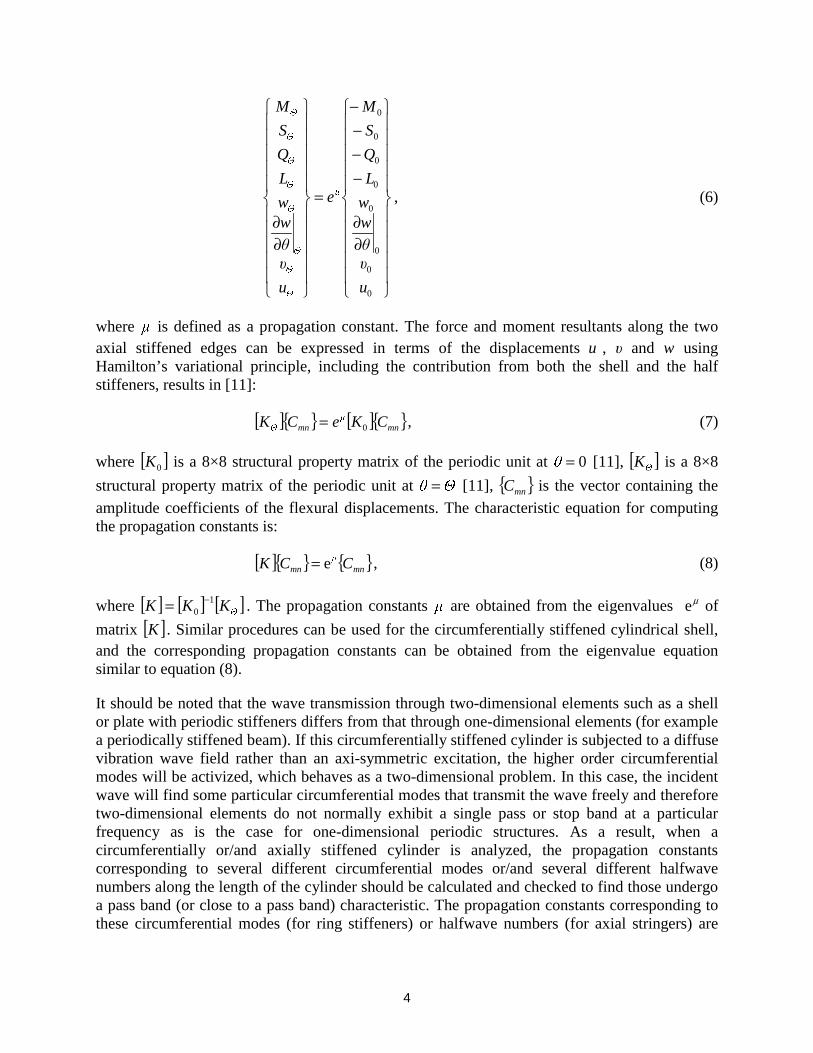
The edge displacements and force/moment resultants acting on the edges of a periodic section (Figure 1(b)) are related by the following equation [11]:
4
∂∂
−−−−
=
∂∂
0
0
0
0
0
0
0
0
u
υ
θ
ww
L
Q
S
M
e
u
υ
θ
ww
L
Q
S
M
µ
Θ
Θ
Θ
Θ
Θ
Θ
Θ
Θ
, (6)
where µ is defined as a propagation constant. The force and moment resultants along the two axial stiffened edges can be expressed in terms of the displacements u , υ and w using Hamilton’s variational principle, including the contribution from both the shell and the half stiffeners, results in [11]:
[ ]{ } [ ]{ }mnµ
mnΘ CKeCK 0= , (7)
where [ ]0K is a 8×8 structural property matrix of the periodic unit at 0=θ [11], [ ]Θ
K is a 8×8
structural property matrix of the periodic unit at Θθ = [11], { }mnC is the vector containing the
amplitude coefficients of the flexural displacements. The characteristic equation for computing the propagation constants is:
[ ]{ } { }mnµ
mn CCK e= , (8)
where [ ] [ ] [ ]Θ
KKK 10
−= . The propagation constants µ are obtained from the eigenvalues µe of
matrix [ ]K . Similar procedures can be used for the circumferentially stiffened cylindrical shell, and the corresponding propagation constants can be obtained from the eigenvalue equation similar to equation (8).
It should be noted that the wave transmission through two-dimensional elements such as a shell or plate with periodic stiffeners differs from that through one-dimensional elements (for example a periodically stiffened beam). If this circumferentially stiffened cylinder is subjected to a diffuse vibration wave field rather than an axi-symmetric excitation, the higher order circumferential modes will be activized, which behaves as a two-dimensional problem. In this case, the incident wave will find some particular circumferential modes that transmit the wave freely and therefore two-dimensional elements do not normally exhibit a single pass or stop band at a particular frequency as is the case for one-dimensional periodic structures. As a result, when a circumferentially or/and axially stiffened cylinder is analyzed, the propagation constants corresponding to several different circumferential modes or/and several different halfwave numbers along the length of the cylinder should be calculated and checked to find those undergo a pass band (or close to a pass band) characteristic. The propagation constants corresponding to these circumferential modes (for ring stiffeners) or halfwave numbers (for axial stringers) are
5
used to determine the power transfer coefficients at the stiffeners for EFEA in the following derivation.
DERIVATION OF JOINT MATRIX FOR A PERIODIC AXIAL STRINGER
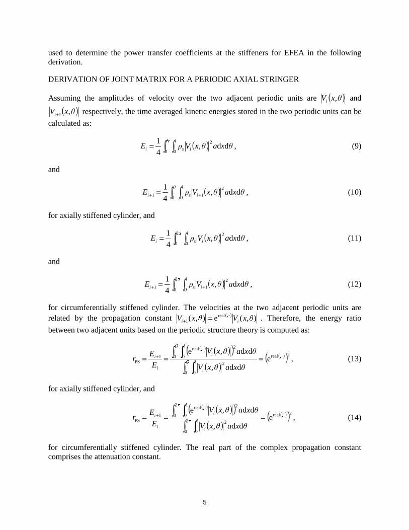
Assuming the amplitudes of velocity over the two adjacent periodic units are ( )θxVi , and
( )θxVi ,1+ respectively, the time averaged kinetic energies stored in the two periodic units can be
calculated as:
( )∫ ∫=Θ l
isi θxaθxVρE0 0
2dd,
4
1, (9)
and
( )∫ ∫ ++ =Θ l
isi θxaθxVρE0 0
2
11 dd,4
1, (10)
for axially stiffened cylinder, and
( )∫ ∫=π l
isi θxaθxVρE2
0 0
2dd,
4
1, (11)
and
( )∫ ∫ ++ =π l
isi θxaθxVρE2
0 0
2
11 dd,4
1, (12)
for circumferentially stiffened cylinder. The velocities at the two adjacent periodic units are related by the propagation constant ( ) ),(e),( real
1 θxVθxV iµ
i =+ . Therefore, the energy ratio
between two adjacent units based on the periodic structure theory is computed as:
( ) ( )( )( )
( )( )2real
0 0
2
0 0
2real
1PS e
dd,
dd,eµ
Θ l
i
Θ l
iµ
i
i
θxaθxV
θxaθxV
E
Er ===
∫ ∫
∫ ∫+ , (13)
for axially stiffened cylinder, and
( ) ( )( )( )
( )( )2real2
0 0
2
2
0 0
2real
1PS e
dd,
dd,eµ
π l
i
π l
iµ
i
i
θxaθxV
θxaθxV
E
Er ===
∫ ∫
∫ ∫+ , (14)
for circumferentially stiffened cylinder. The real part of the complex propagation constant comprises the attenuation constant.
6
The power transfer coefficients associated with the bending energy transmitted and reflected from the periodic stiffeners are evaluated from the energy ratio PSr computed by the PS theory
for two adjacent units. An iterative algorithm [15] is employed here in order to compute the appropriate power transfer coefficients from the energy ratio evaluated by the PS theory. This algorithm was developed and utilized in the past for computing power transfer characteristics for spot-welded panels in automotive applications. An EFEA model comprised of two adjacent periodic cylindrical bays is constructed. One bay is defined as the excited section and the other comprises the receiving bay. The total energy stored at two bays is computed by the EFEA formulation while the EFEA system matrix is a function of the unknown power transfer coefficients. The iterative algorithm provides the values for the EFEA power transfer coefficients which account for the periodic characteristics of the axial stringers. The power transfer coefficients are utilized in the computation of the joint matrix [2]
∫−+−=
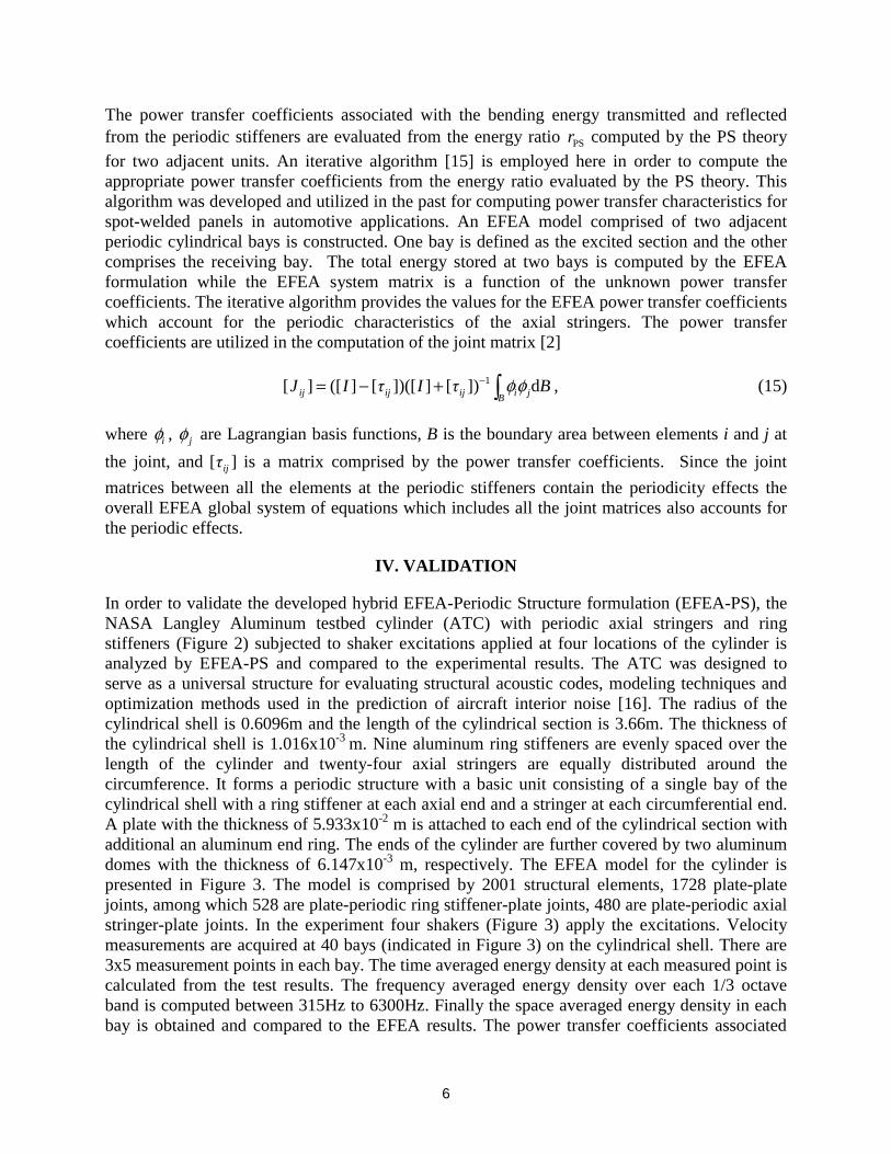
B jiijijij BτIτIJ d])[]])([[]([][ 1 φφ , (15)
where iφ , jφ are Lagrangian basis functions, B is the boundary area between elements i and j at
the joint, and ][ ijτ is a matrix comprised by the power transfer coefficients. Since the joint
matrices between all the elements at the periodic stiffeners contain the periodicity effects the overall EFEA global system of equations which includes all the joint matrices also accounts for the periodic effects.
IV. VALIDATION
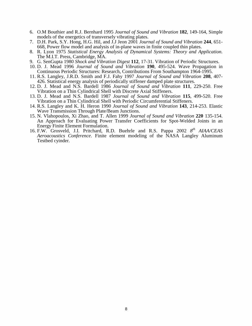
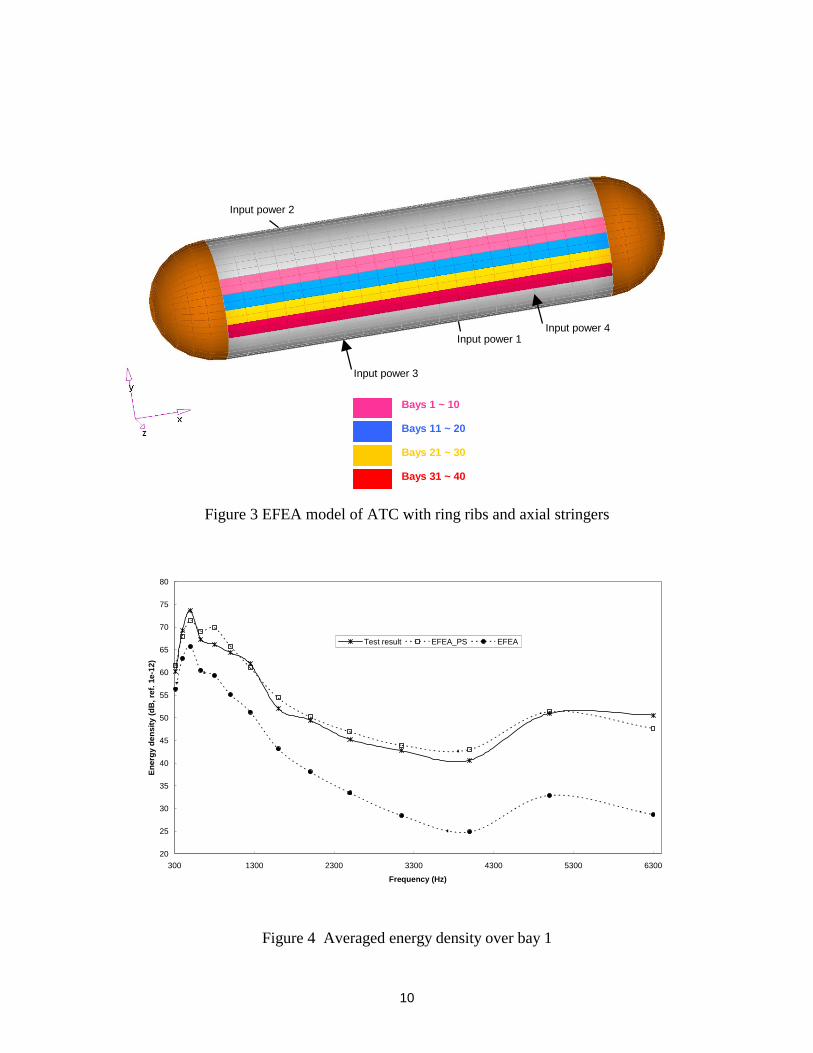
In order to validate the developed hybrid EFEA-Periodic Structure formulation (EFEA-PS), the NASA Langley Aluminum testbed cylinder (ATC) with periodic axial stringers and ring stiffeners (Figure 2) subjected to shaker excitations applied at four locations of the cylinder is analyzed by EFEA-PS and compared to the experimental results. The ATC was designed to serve as a universal structure for evaluating structural acoustic codes, modeling techniques and optimization methods used in the prediction of aircraft interior noise [16]. The radius of the cylindrical shell is 0.6096m and the length of the cylindrical section is 3.66m. The thickness of the cylindrical shell is 1.016x10⁻³ m. Nine aluminum ring stiffeners are evenly spaced over the length of the cylinder and twenty-four axial stringers are equally distributed around the circumference. It forms a periodic structure with a basic unit consisting of a single bay of the cylindrical shell with a ring stiffener at each axial end and a stringer at each circumferential end. A plate with the thickness of 5.933x10⁻² m is attached to each end of the cylindrical section with additional an aluminum end ring. The ends of the cylinder are further covered by two aluminum domes with the thickness of 6.147x10⁻³ m, respectively. The EFEA model for the cylinder is presented in Figure 3. The model is comprised by 2001 structural elements, 1728 plate-plate joints, among which 528 are plate-periodic ring stiffener-plate joints, 480 are plate-periodic axial stringer-plate joints. In the experiment four shakers (Figure 3) apply the excitations. Velocity measurements are acquired at 40 bays (indicated in Figure 3) on the cylindrical shell. There are 3x5 measurement points in each bay. The time averaged energy density at each measured point is calculated from the test results. The frequency averaged energy density over each 1/3 octave band is computed between 315Hz to 6300Hz. Finally the space averaged energy density in each bay is obtained and compared to the EFEA results. The power transfer coefficients associated
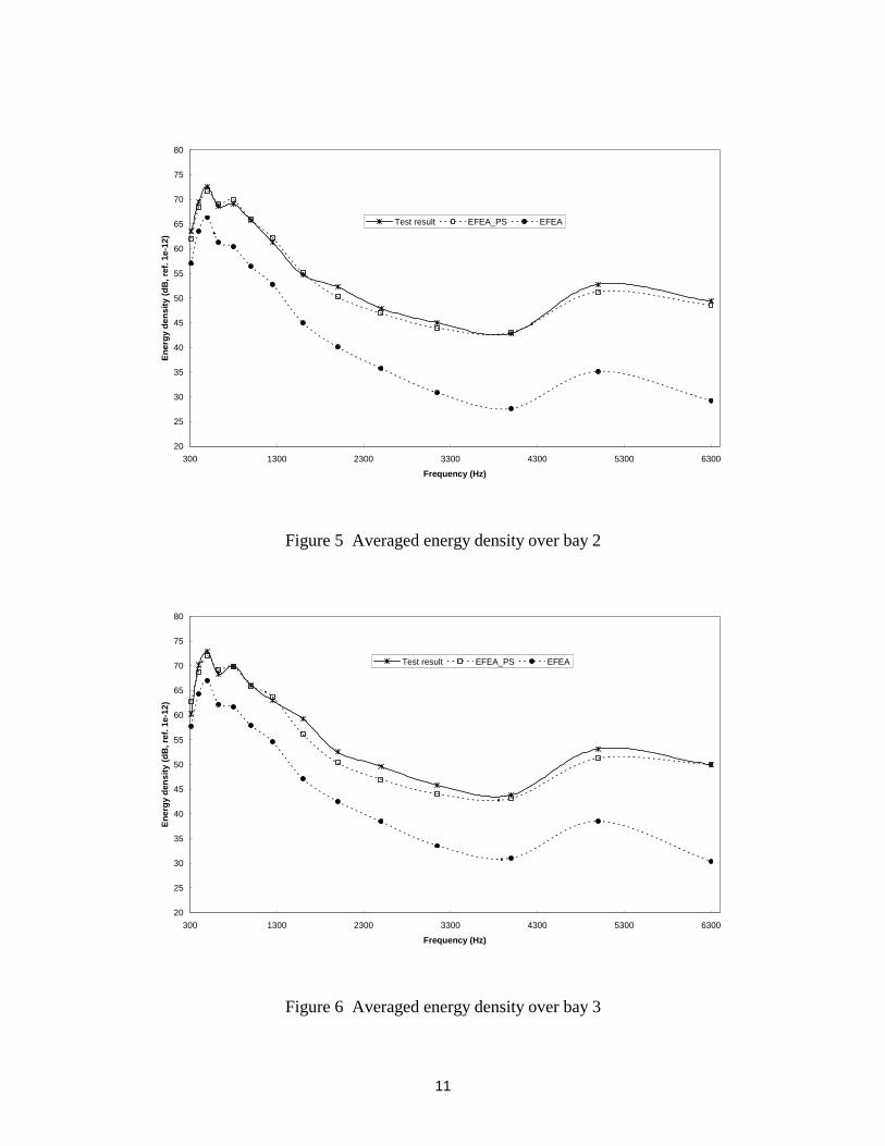
7
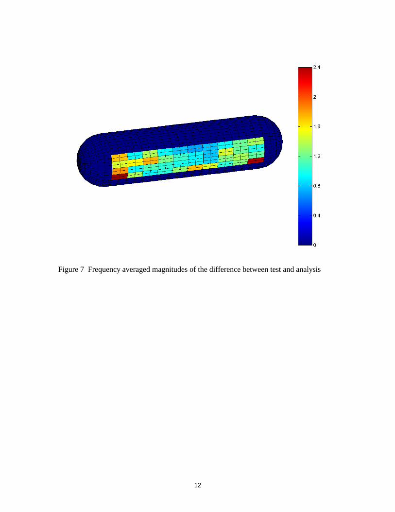
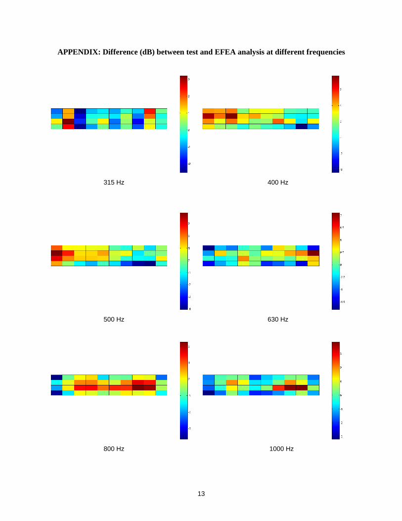
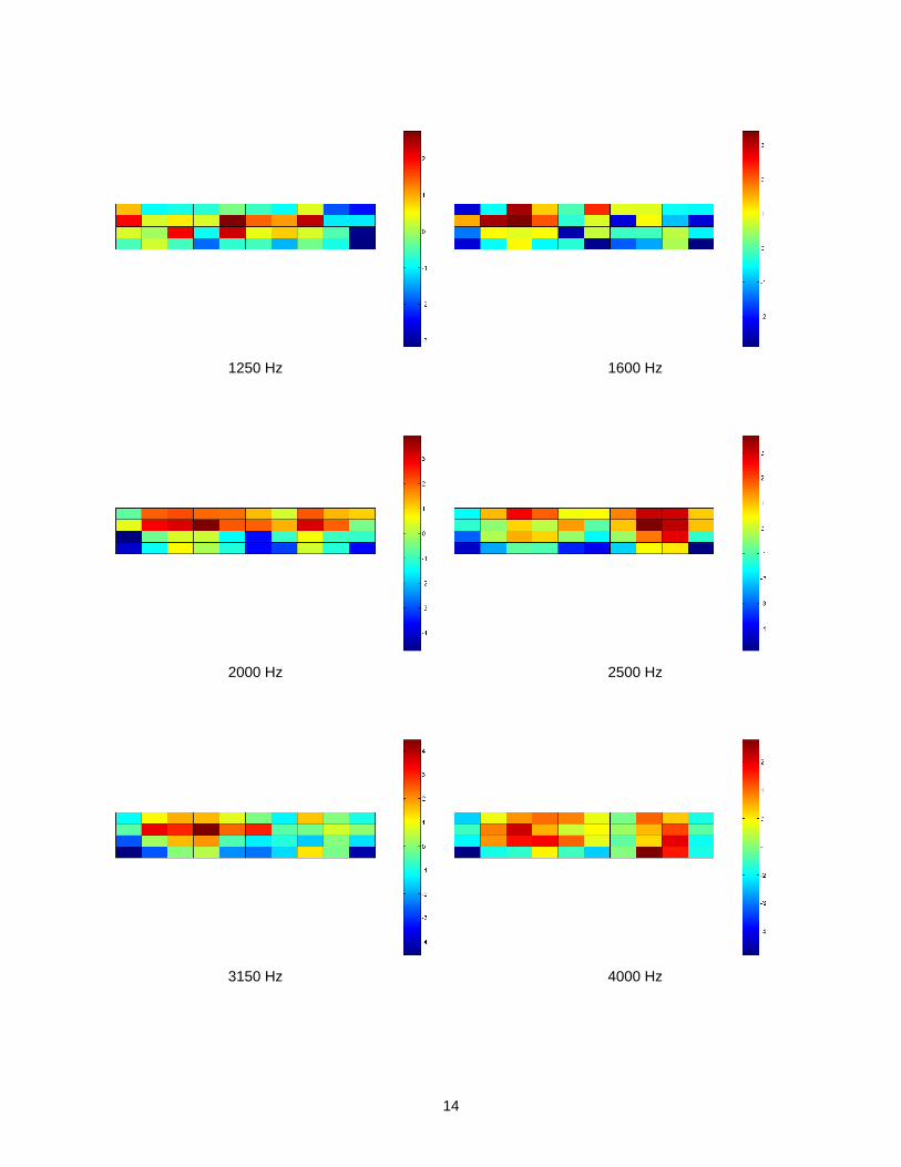
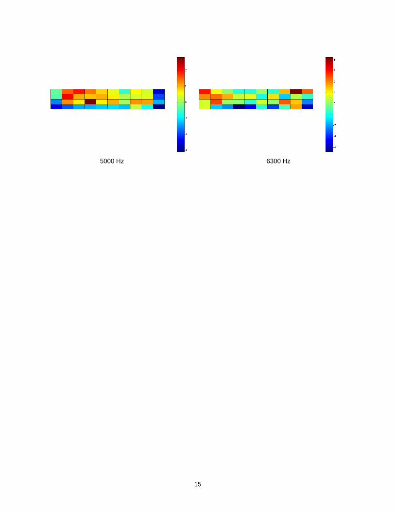
with the axial and circumferential stiffeners are calculated and used in the EFEA-PS computations. The propagation constants corresponding to different circumferential modes and different halfwave numbers along the length of the longitudinal bay are calculated. Those which undergo a pass band are selected, and they are used to determine the power transfer coefficients. The energy densities are compared between the EFEA-PS method and experiment. Results for the axially consecutive bay 1 ~ bay 3 are depicted in Figures 4 ~ 6, respectively. Good correlation is observed between the EFEA-PS method and experiment. Results computed by the EFEA method with power transfer coefficients that account for the stiffener base on [2, 14] but not for the periodicity of the structure are also presented for comparison. As it can be observed a considerably lesser amount of power is transferred to the receiving units if the periodic effects are not taken into account. It can be observed that the EFEA-PS method captures well the periodic characteristics for both the axial stringers and ring stiffeners. Figure 7 presents the frequency averaged magnitudes of the difference between test and analysis for all 40 bays. In the Appendix, the difference between the test data and the numerical results at each 1/3 octave band from 315Hz up to 6,300Hz is presented for all 40 bays where measurements were collected.
CONCLUSION
A hybrid method that combines the EFEA and the PS theory for analyzing the high frequency vibration of a cylindrical shell stiffened by the periodically circumferential stiffeners and axial stringers is developed. The periodic stiffeners are accounted in the derivation of the power transfer coefficients and in the derivation of the joint matrices in the EFEA. Since the two-dimensional periodic structures do not normally exhibit a single pass or stop band at a particular frequency as is the case for one-dimensional periodic structures, the propagation constants corresponding to several different circumferential modes or/and several different halfwave numbers along the length of the cylinder should be calculated to find those undergo a pass band characteristic when a circumferentially and axially stiffened cylinder is analyzed. The propagation constants corresponding to these circumferential modes (for ring stiffeners) or halfwave numbers (for axial stringers) should be used to determine the power transfer coefficients at the stiffeners for EFEA computations.
REFERENCES
1. N. Vlahopoulos, L.O. Garza-Rios and C. Mollo 1999 Journal of Ship Research 43, 143-156. Numerical implementation, validation, and marine applications of an energy finite element formulation.
2. W. Zhang, A. Wang, N. Vlahopoulos, K. Wu, 2003 Journal of Sound and Vibration 263, 21-46. High frequency vibration analysis of thin elastic plates under heavy fluid loading by an energy finite element formulation.
3. W. Zhang, A. Wang, N. Vlahopoulos 2002 Finite Elements in Analysis and Design 38,1095-1113, An alternative energy finite element formulation based on incoherent orthogonal waves and its validation for marine structures.
4. W. Zhang, N. Vlahopoulos and K. Wu, Journal of Sound and Vibration Vol. 282, April 22 2005, p. 679-700 An energy finite element formulation for high frequency vibration analysis of externally fluid-loaded cylindrical shells with periodic circumferential stiffeners subjected to axi-symmetric excitation.
5. R.J. Bernhard, J.E. Huff 1999 Journal of Vibration and Acoustics 121, 295-301, Structure-acoustic design at high frequency using the energy finite element method.
8
6. O.M Bouthier and R.J. Bernhard 1995 Journal of Sound and Vibration 182, 149-164, Simple models of the energetics of transversely vibrating plates.
7. D.H. Park, S.Y. Hong, H.G. Hil, and J.J Jeon 2001 Journal of Sound and Vibration 244, 651-668, Power flow model and analysis of in-plane waves in finite coupled thin plates.
8. R. Lyon 1975 Statistical Energy Analysis of Dynamical Systems: Theory and Application. The M.I.T. Press, Cambridge, MA.
9. G. SenGupta 1980 Shock and Vibration Digest 112, 17-31. Vibration of Periodic Structures. 10. D. J. Mead 1996 Journal of Sound and Vibration 190, 495-524. Wave Propagation in
Continuous Periodic Structures: Research, Contributions From Southampton 1964-1995. 11. R.S. Langley, J.R.D. Smith and F.J. Fahy 1997 Journal of Sound and Vibration 208, 407-
426. Statistical energy analysis of periodically stiffener damped plate structures. 12. D. J. Mead and N.S. Bardell 1986 Journal of Sound and Vibration 111, 229-250. Free
Vibration on a Thin Cylindrical Shell with Discrete Axial Stiffeners. 13. D. J. Mead and N.S. Bardell 1987 Journal of Sound and Vibration 115, 499-520. Free
Vibration on a Thin Cylindrical Shell with Periodic Circumferential Stiffeners. 14. R.S. Langley and K. H. Heron 1990 Journal of Sound and Vibration 143, 214-253. Elastic
Wave Transmission Through Plate/Beam Junctions. 15. N. Vlahopoulos, Xi Zhao, and T. Allen 1999 Journal of Sound and Vibration 220 135-154.
An Approach for Evaluating Power Transfer Coefficients for Spot-Welded Joints in an Energy Finite Element Formulation.
16. F.W. Grosveld, J.I. Pritchard, R.D. Buehrle and R.S. Pappa 2002 8th AIAA/CEAS Aeroacoustics Conference. Finite element modeling of the NASA Langley Aluminum Testbed cyinder.
9
(a) (b)
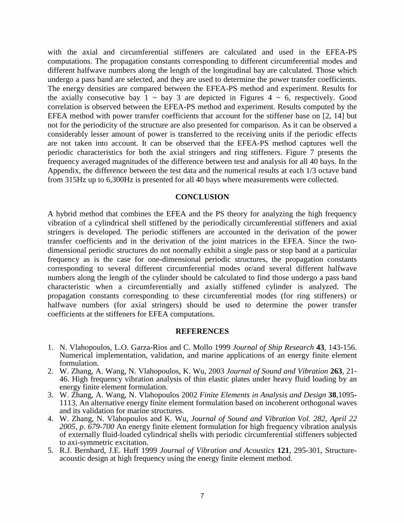
Figure 1 (a) A periodic axial stiffened cylindrical shell and the corresponding coordinate system. (b) One periodic section (including one bay cylindrical shell and a half stiffener
attached axially at each end)
Figure 2 Aluminum Testbed Cylinder (ATC) with the stringer and ring ribs
( )wz( )υy
l
( )uxa
θ0L
0S 0Q 0=θ
Θθ =
0M
10
Figure 3 EFEA model of ATC with ring ribs and axial stringers
20
25
30
35
40
45
50
55
60
65
70
75
80
300 1300 2300 3300 4300 5300 6300
Frequency (Hz)
En
erg
y d
ensi
ty (
dB
, ref
. 1e-
12)
Test result EFEA_PS EFEA
Figure 4 Averaged energy density over bay 1
Bays 1 ~ 10
Bays 11 ~ 20
Bays 21 ~ 30
Bays 31 ~ 40
Input power 4
Input power 3
Input power 2
Input power 1
11
20
25
30
35
40
45
50
55
60
65
70
75
80
300 1300 2300 3300 4300 5300 6300
Frequency (Hz)
En
erg
y d
ensi
ty (
dB
, ref
. 1e-
12)
Test result EFEA_PS EFEA
Figure 5 Averaged energy density over bay 2
20
25
30
35
40
45
50
55
60
65
70
75
80
300 1300 2300 3300 4300 5300 6300
Frequency (Hz)
En
erg
y d
ensi
ty (
dB
, ref
. 1e-
12)
Test result EFEA_PS EFEA
Figure 6 Averaged energy density over bay 3
12
Figure 7 Frequency averaged magnitudes of the difference between test and analysis
13
APPENDIX: Difference (dB) between test and EFEA analysis at different frequencies
315 Hz 400 Hz
500 Hz 630 Hz
800 Hz 1000 Hz
14
1250 Hz 1600 Hz
2000 Hz 2500 Hz
3150 Hz 4000 Hz
15
5000 Hz 6300 Hz
REPORT DOCUMENTATION PAGE Form ApprovedOMB No. 0704-0188
2. REPORT TYPE
Contractor Report 4. TITLE AND SUBTITLE
Energy Finite Element Analysis for Computing the High Frequency Vibration of the Aluminum Testbed Cylinder and Correlating the Results to Test Data
5a. CONTRACT NUMBER
6. AUTHOR(S)
Vlahopoulos, Nickolas
7. PERFORMING ORGANIZATION NAME(S) AND ADDRESS(ES)
NASA Langley Research Center University of MichiganHampton, VA 23681-2199 Ann Arbor, MI 48109
9. SPONSORING/MONITORING AGENCY NAME(S) AND ADDRESS(ES)
National Aeronautics and Space AdministrationWashington, DC 20546-0001
8. PERFORMING ORGANIZATION REPORT NUMBER
10. SPONSOR/MONITOR'S ACRONYM(S)
NASA
13. SUPPLEMENTARY NOTESLangley Technical Monitor: Ralph D. BuehrleAn electronic version can be found at http://ntrs.nasa.gov
12. DISTRIBUTION/AVAILABILITY STATEMENTUnclassified - UnlimitedSubject Category 64Availability: NASA CASI (301) 621-0390
19a. NAME OF RESPONSIBLE PERSON
STI Help Desk (email: [email protected])
14. ABSTRACT
A hybrid method that combines the Energy Finite Element Analysis (EFEA) and the Periodic Structures (PS) theory for analyzing the high frequency vibration of a cylindrical shell stiffened by the periodically circumferential stiffeners and axial stringers is developed. The periodic stiffeners are accounted for in the derivation of the power transfer coefficients and in the derivation of the joint matrices in the EFEA. In order to validate the developed hybrid EFEA-Periodic Structure formulation (EFEA-PS), the NASA Langley Aluminum testbed cylinder (ATC) with periodic axial stringers and ring stiffeners subjected to shaker excitations applied at four locations of the cylinder is analyzed by EFEA-PS and compared to the experimental results. Good correlation is observed between the EFEA-PS method and experiment.
15. SUBJECT TERMS
Energy Finite Element Analysis (EFEA); Periodic structure; Stiffened cylinder; Vibration
18. NUMBER OF PAGES
20
19b. TELEPHONE NUMBER (Include area code)
(301) 621-0390
a. REPORT
U
c. THIS PAGE
U
b. ABSTRACT
U
17. LIMITATION OF ABSTRACT
UU
Prescribed by ANSI Std. Z39.18Standard Form 298 (Rev. 8-98)
3. DATES COVERED (From - To)
5b. GRANT NUMBER
5c. PROGRAM ELEMENT NUMBER
5d. PROJECT NUMBER
NCC1-030215e. TASK NUMBER
5f. WORK UNIT NUMBER
23-781-20-11
11. SPONSOR/MONITOR'S REPORT NUMBER(S)
NASA/CR-2005-213760
16. SECURITY CLASSIFICATION OF:
The public reporting burden for this collection of information is estimated to average 1 hour per response, including the time for reviewing instructions, searching existing data sources, gathering and maintaining the data needed, and completing and reviewing the collection of information. Send comments regarding this burden estimate or any other aspect of this collection of information, including suggestions for reducing this burden, to Department of Defense, Washington Headquarters Services, Directorate for Information Operations and Reports (0704-0188), 1215 Jefferson Davis Highway, Suite 1204, Arlington, VA 22202-4302. Respondents should be aware that notwithstanding any other provision of law, no person shall be subject to any penalty for failing to comply with a collection of information if it does not display a currently valid OMB control number.PLEASE DO NOT RETURN YOUR FORM TO THE ABOVE ADDRESS.
1. REPORT DATE (DD-MM-YYYY)
06 - 200501-