Embed Size (px)
Citation preview

ENERGY EFFICIENT VIDEO TRANSMISSION USING
COOPERATION OF LTE AND WLAN
by
Maryam Hamidirad
B.Eng., Sharif University of Technology, 2009
A THESIS SUBMITTED IN PARTIAL FULFILLMENT
OF THE REQUIREMENTS FOR THE DEGREE OF
Master of Applied Science
in the
School of Com puting Science
Faculty of Applied Sciences
© Maryam Hamidirad 2012
SIMON FRASER UNIVERSITY
Summer 2012
All rights reserved.
However, in accordance with the Copyright Act of Canada, this work may be
reproduced without authorization under the conditions for "Fair Dealing."
Therefore, limited reproduction of this work for the purposes of private study,
research, criticism, review and news reporting is likely to be in accordance
with the law, particularly if cited appropriately.

APPROVAL
Name: Maryam Hamidirad
Degree: Master of Applied Science
Title of Thesis: Energy Efficient Video Transmission using Cooperation of
LTE and WLAN
Examining Committee: Dr. Gabor Tardos
Chair
Dr. Qianping Gu, Senior Supervisor
Dr. Art Liestman, Co-Senior Supervisor
Dr. Jiangchuan Liu, SFU Examiner
Date Approved:
ii

Partial Copyright Licence

Abstract
Long Term Evolution (LTE) networks are a new generation of networks to meet the increas-
ing demand for multimedia services in wireless networks. Energy efficient data delivery is a
key issue in LTE networks. In this thesis, a cooperative mechanism is proposed to decrease
the energy consumption in the downlink channel of LTE networks for multicast. In this
approach, users in the LTE cell are grouped into clusters based on their distance from the
base station. Then, a cluster header is chosen for each group based on a utility function
that evaluates user satisfaction after each transmission. Cluster headers receive data di-
rectly from the base station and they are responsible to relay data to other users in their
cluster using Wireless Local Area Network (WLAN). Simulations show that our approach
reduces power consumption of the base station by 5% to 25% compared to conventional
multicast transmission mechanism. The cooperative mechanism also helps mobile users to
save energy on data receiving.
iii

To my parents and my family
iv
Acknowledgments
I would like to gratefully thank my senior supervisor, Dr. Qianping Gu, for guiding me
through my graduate research as this thesis could not have been produced without his
thorough help and supervision. I would also like to express my gratitude towards my co-
senior supervisor, Dr. Art Liestman, for his support and guidance at all stages of my time
as a graduate student in SFU Computing Science. I would like to thank Dr. Jiangchuan
Liu for being in my thesis committee. I would also like to thank my colleagues for giving
me many directions during my research work.
Special thanks goes to my friend, Soroush Norouzi, whose friendship I hold dear and
would like to express my appreciation for all his love and support.
v

Contents
Approval ii
Abstract iii
Dedication iv
Acknowledgments v
Contents vi
List of Tables viii
List of Figures ix
1 Introduction 1
1.1 Motivation . . . . . . . . . . . . . . . . . . . . . . . . . . . . . . . . . . . . . 1
1.2 Contribution . . . . . . . . . . . . . . . . . . . . . . . . . . . . . . . . . . . . 3
1.3 Thesis Structure . . . . . . . . . . . . . . . . . . . . . . . . . . . . . . . . . . 4
2 Background 5
2.1 LTE Basics . . . . . . . . . . . . . . . . . . . . . . . . . . . . . . . . . . . . . 5
2.1.1 LTE Features . . . . . . . . . . . . . . . . . . . . . . . . . . . . . . . . 6
2.1.2 LTE Network Architecture . . . . . . . . . . . . . . . . . . . . . . . . 6
2.1.3 LTE Downlink Protocol Stack . . . . . . . . . . . . . . . . . . . . . . . 9
2.1.4 LTE Channels . . . . . . . . . . . . . . . . . . . . . . . . . . . . . . . 10
2.2 MBMS Services . . . . . . . . . . . . . . . . . . . . . . . . . . . . . . . . . . . 11
2.2.1 MBMS Introduction . . . . . . . . . . . . . . . . . . . . . . . . . . . . 11
vi
2.2.2 MBMS Modes . . . . . . . . . . . . . . . . . . . . . . . . . . . . . . . 12
2.3 Wireless LAN Basics . . . . . . . . . . . . . . . . . . . . . . . . . . . . . . . . 13
2.4 Related Work . . . . . . . . . . . . . . . . . . . . . . . . . . . . . . . . . . . . 14
3 Proposed Cooperative System 17
3.1 Clustering Mechanism . . . . . . . . . . . . . . . . . . . . . . . . . . . . . . . 17
3.2 Scheduling Algorithm . . . . . . . . . . . . . . . . . . . . . . . . . . . . . . . 22
3.3 Base Station Power Setting . . . . . . . . . . . . . . . . . . . . . . . . . . . . 25
4 Simulation 27
4.1 Simulation Procedure . . . . . . . . . . . . . . . . . . . . . . . . . . . . . . . 27
4.2 Simulation Parameters . . . . . . . . . . . . . . . . . . . . . . . . . . . . . . . 29
4.3 Simulation Scenario . . . . . . . . . . . . . . . . . . . . . . . . . . . . . . . . 31
4.4 Experimental Results and Analysis . . . . . . . . . . . . . . . . . . . . . . . . 32
5 Conclusion and Future Work 37
5.1 Contribution Summary . . . . . . . . . . . . . . . . . . . . . . . . . . . . . . . 37
5.2 Future Work . . . . . . . . . . . . . . . . . . . . . . . . . . . . . . . . . . . . 38
Bibliography 39
vii

List of Tables
2.1 UE CATEGORIES . . . . . . . . . . . . . . . . . . . . . . . . . . . . . . . . . 8
4.1 CQI TO SINR MAPPING . . . . . . . . . . . . . . . . . . . . . . . . . . . . . 29
4.2 PEDESTRIAN A CHANNEL MODEL . . . . . . . . . . . . . . . . . . . . . 31
4.3 SIMULATION PARAMETERS . . . . . . . . . . . . . . . . . . . . . . . . . . 32
viii
List of Figures
2.1 LTE Architecture (Adapted from [1]) . . . . . . . . . . . . . . . . . . . . . . 8
2.2 LTE Protocol Stack (Adapted from [2]) . . . . . . . . . . . . . . . . . . . . . 9
2.3 Downlink Channel Mapping (Adapted from [2]) . . . . . . . . . . . . . . . . . 11
2.4 MBMS Architecture (Adapted from [14]) . . . . . . . . . . . . . . . . . . . . 12
3.1 Different Forms of Utility Function (Adapted from [21]) . . . . . . . . . . . . 18
3.2 Dividing Cell into Concentric Tiers . . . . . . . . . . . . . . . . . . . . . . . . 20
3.3 Data Transmission in Clustering Mode . . . . . . . . . . . . . . . . . . . . . . 20
3.4 Generalized Model of Downlink Packet Scheduler (Adapted from [7]) . . . . . 23
4.1 Simulation of Downlink Power Consumption Data . . . . . . . . . . . . . . . 33
4.2 Average Downlink Power Consumption . . . . . . . . . . . . . . . . . . . . . . 34
4.3 Average Packet Delay . . . . . . . . . . . . . . . . . . . . . . . . . . . . . . . 35
4.4 Average Packet Delay for clustering and PTM approach . . . . . . . . . . . . 35
ix
Chapter 1
Introduction
In this chapter, we briefly introduce multimedia services in Long Term Evolution (LTE)
networks and explain our motivation to improve resource efficiency for provision of these
services. Then, we describe our power saving mechanism to address the resource utilization
and summarize the contribution of this research. Finally, the structure for the rest of this
thesis is presented.
1.1 Motivation
As mobile network technology moves forward, mobile data and video applications become
more and more popular and video will be the dominant form of traffic in wireless networks.
Motivated by the increasing need for high data rates and quality of service for video applica-
tions, the 3rd Generation Partnership Project (3GPP) has introduced LTE networks in its
Release 8 [1]. Migration from third generation (3G) networks to LTE has opened new doors
in the wireless network industry and has provided great performance improvements. The
LTE technology provides a downlink data rate of up to 150 Megabits per second (Mbps)
and in uplink it can provide up to 50 Mbps data rates over a wide area. Achieving these
high data rates has enabled cellular wireless networks to support high-speed multimedia
applications such as Voice over Internet Protocol (VoIP), multimedia streaming and video
conferencing [2].
Aligned with these improvements and increased rate of the multimedia services Evolved
Multimedia Broadcast Multicast Service (MBMS) was introduced to deliver high data rate
applications to many users efficiently. LTE standard has improved MBMS by decreasing the
1
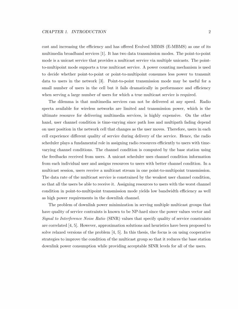
CHAPTER 1. INTRODUCTION 2
cost and increasing the efficiency and has offered Evolved MBMS (E-MBMS) as one of its
multimedia broadband services [1]. It has two data transmission modes. The point-to-point
mode is a unicast service that provides a multicast service via multiple unicasts. The point-
to-multipoint mode supports a true multicast service. A power counting mechanism is used
to decide whether point-to-point or point-to-multipoint consumes less power to transmit
data to users in the network [3]. Point-to-point transmission mode may be useful for a
small number of users in the cell but it fails dramatically in performance and efficiency
when serving a large number of users for which a true multicast service is required.
The dilemma is that multimedia services can not be delivered at any speed. Radio
specta available for wireless networks are limited and transmission power, which is the
ultimate resource for delivering multimedia services, is highly expensive. On the other
hand, user channel condition is time-varying since path loss and multipath fading depend
on user position in the network cell that changes as the user moves. Therefore, users in each
cell experience different quality of service during delivery of the service. Hence, the radio
scheduler plays a fundamental role in assigning radio resources efficiently to users with time-
varying channel conditions. The channel condition is computed by the base station using
the feedbacks received from users. A unicast scheduler uses channel condition information
from each individual user and assigns resources to users with better channel condition. In a
multicast session, users receive a multicast stream in one point-to-multipoint transmission.
The data rate of the multicast service is constrained by the weakest user channel condition,
so that all the users be able to receive it. Assigning resources to users with the worst channel
condition in point-to-multipoint transmission mode yields low bandwidth efficiency as well
as high power requirements in the downlink channel.
The problem of downlink power minimization in serving multiple multicast groups that
have quality of service contraints is known to be NP-hard since the power values vector and
Signal to Interference Noise Ratio (SINR) values that specify quality of service constraints
are correlated [4, 5]. However, approximation solutions and heuristics have been proposed to
solve relaxed versions of the problem [4, 5]. In this thesis, the focus is on using cooperative
strategies to improve the condition of the multicast group so that it reduces the base station
downlink power consumption while providing acceptable SINR levels for all of the users.

CHAPTER 1. INTRODUCTION 3
1.2 Contribution
In this thesis, we propose a cooperative mechanism to reduce the downlink power consump-
tion in LTE networks. First, a clustering method is applied to divide users into multiple
multicast clusters. Then, a cluster header is chosen for each cluster that receives data di-
rectly through the LTE interface. Cluster headers are responsible to relay data to users in
their cluster using Wireless Local Area Network (WLAN). Moreover, they are alternately
switched after each transmission to guarantee the fairness of our approach and to motivate
users to cooperate.
The most critical part in clustering algorithms is choosing cluster headers. We use a
user utility function that demonstrates users’ satisfaction. The function is computed for all
the users in one cluster. The user with the highest utility value is chosen as the cluster
header. Afterwards, resource blocks are assigned to cluster headers based on the scheduling
metric used in one of the well-known scheduling algorithms named Proportional Fair [6].
It assigns radio resources to users so as to balance fairness and maximize users’ average
throughput [6, 7]. For each resource block, the transmission power is set to guarantee the
specified SINR level achieved at the receiving end.
In the proposed cooperative mechanism, a cluster header receives data in LTE mode
and then relays data to other users in WLAN mode. Previous research [8, 9, 10] shows that
the cooperation of LTE or Wide Metropolitan Area Network (WMAN) and WLAN can help
mobile users save energy and increase their battery life since it is more energy efficient for
a mobile user to work in the WLAN mode. More specifically, Liu et al. [8, 9] experimented
on the cooperation of WMAN and WLAN and found that this prolongs battery life for both
the user and the base station.
To evaluate the performance of the proposed mechanism, we have used an open-source
simulator called LTE-Sim which simulates different layers of LTE networks. In order to
perform the simulation, multicast transmission is implemented in the LTE network. This
requires modification in different layers of the LTE protocol stack. Moreover, a clustering
scheduler and a multicast scheduler are implemented in the Medium Access Control (MAC)
layer. We have also simulated conventional point-to-multipoint and point-to-point MBMS
transmission modes that use non-cooperative packet schedulers and compared average down-
link power consumption and average packet delay to that achieved by our approach.
Numerical results show that our approach outperforms point-to-multipoint non-cooperative

CHAPTER 1. INTRODUCTION 4
schedulers in average power consumption and results in a 5% to 25% decrease in downlink
power consumption. The point-to-point approach consumes less downlink power compared
to our approach; however, the average packet delay achieved is not acceptable for multime-
dia applications. Our system also achieves lower average packet delay than achieved by the
point-to-multipoint approach.
1.3 Thesis Structure
The rest of this thesis is structured as follows. In Chapter 2, background information and
previous research in this area are presented. Chapter 3 formulates our problem and proposes
our approach for solving it. Experimental results of our approach are provided and analyzed
in Chapter 4. Finally, Chapter 5 contains the conclusion of this thesis.

Chapter 2
Background
In this chapter, we will provide some background information about LTE networks. At
first, we will present a summary of the features of LTE networks. Then the architecture and
main nodes of the physical layer design are presented. Afterwards, MBMS services that are
studied in this thesis are introduced. Finally, related work that has been done on the thesis
topic is summarized.
2.1 LTE Basics
The rapid growth of IP traffic and data consumption, migration from text-based services
to high speed multimedia services (like video sharing, video streaming, and IPTV), and
improvements in mobile technology have motivated wireless technology to provide faster
and more efficient networks [2, 11, 12].
The 3rd Generation Partnership Project (3GPP) introduced 3G technology to improve
globalization of wireless communication standards. However, 3G networks have only im-
proved over second generation networks in data rate, spectral efficiency, and channel quality.
One of the main techonologies that is offered in 3G is called third generation Universal Mo-
bile Telecommunications System (UMTS) which uses Universal Terrestrial Radio Access
Network (UTRAN) and Global System for Mobile/Enhanced Data rates for GSM Evolution
(GSM/EDGE) radio access network as its main components. UMTS supports bit rates up
to 42Mbps and offers both real time and non-real time services (like video conferencing,
IPTV, audio, and video streaming support, and high-speed web browsing).
The latest standard for wireless communication networks is LTE, based on GSM/EDGE
5

CHAPTER 2. BACKGROUND 6
and UMTS. Subsequent changes in protocols, frame sizes, and network architectures have
improved the performance of this network resulting in lower latency, higher spectral effi-
ciency, and higher capacity compared to its predecessors [13].
2.1.1 LTE Features
In order for LTE to support high speed multimedia services, there have been some changes
in the design of the network. We now describe the features of LTE based on the 3GPP
specification release 8 [1, 11, 14].
One goal was to achieve higher throughput and lower latency. LTE supports high peak
data for 150 Mbps in downlink and 50 Mbps in uplink. The downlink data rate is 3-4
times better and uplink is 2-3 times better than the corresponding rates in UMTS networks.
Moreover, the cell edge data rate has also improved with the same deployment configuration.
LTE also supports delay sensitive applications such as online gaming and VoIP by reducing
the latency of the network. Latency in LTE networks is 20ms compared to 30-40 ms in 3G
networks. In addition, network connections and handoffs for mobile devices is sped up to
350 km/h.
LTE is compatible with 3G and non-3G systems and there is continuity between LTE
and these networks. LTE also has flexible spectra and can operate in different frequency
bandwidths. It allows existing devices to migrate to LTE with different bandwidth capa-
bilities by providing a wide variety of operators. Moreover, LTE provides both paired and
unpaired spectra by supporting the same radio technology for Time Division Duplex (TDD)
and Frequency Division Duplex (FDD).
LTE design avoids hierarchy and has a flat architecture. Unlike existing network archi-
tectures that use circuit switched systems for voice, LTE is all IP based. It offers E-MBMS
to support both voice and multimedia services. It also reduces end user terminal complexity
by having multiple access approaches for multicast and unicast transmission mode. As a
result, it reduces management and deployment costs and technologies.
2.1.2 LTE Network Architecture
In this section, we briefly describe the LTE architecture in order to better understand how
multimedia services are delivered in this network. The overall architecture of LTE consists
of two main elements [1, 2, 15]. EPC provides access to external packet networks based on

CHAPTER 2. BACKGROUND 7
Internet Protocols (IP). While E-UTRAN manages all radio-interface related functions of
the network. In the following, we introduce each of these elements in greater detail.
Evolved Packet Core
The flat architecture of LTE results in one core network that supports all services. EPC is
the core network and is designed to reduce latency, achieve higher capacity, and to support
all IP-based architecture. It supports not only LTE but also legacy networks including 2G
and 3G technologies [11]. EPC consists of four elements [16, 11, 12]: Serving Gateway,
Policy and Charging Rules Function, Packet Data Network Gateway, Mobility Management
Entity.
Serving Gateway is the termination anchor toward the 3GPP radio interface. It manages
mobility of the nodes that move near areas served by different Evolved Node Bs(eNBs). It
is also responsible for packet routing, forwarding, and buffering in the downlink.
Quality of Service (QoS) aspects of the network is managed by Policy and Charging
Rules Function, the software component of the network architecture. It manages charges
and rules on bandwidth, delay, and bit error rate of the flow that is carried by bearers.
Packet Data Network Gateway is the anchor point to packet data networks such as
Internet and private IP network. It is responsible for dynamic IP address allocation, rate
enforcing, service charge policies, and packet filtering.
All functions related to control plane, subscription, session management, and resource
assignment are controlled by Mobility Management Entity. It authorizes and authenticates
services by checking authentication vectors received from users. It also handles mobility
management functions such as users’ location tracking, handover, paging, roaming, and
users’ access to terminals.
E-UTRAN
As shown in Fig 2.1, E-UTRAN consists of Evolved eNBs that are connected to each other
via X2 interface and to EPC using the S1 interface. The eNB is the anchor point between
user equipment (UE) and UTRAN in the user and control plane. More precisely, it is
connected to mobility management entity in the control plane and to serving gateway in
the user plane via S1 interface [1].
One of the main elements of E-UTRAN is eNB that assigns radio resources to users in

CHAPTER 2. BACKGROUND 8
!
"#!!
"#!! "#!!
"#!!
$%!!$%!
!
$%!!
Figure 2.1: LTE Architecture (Adapted from [1])
the downlink and uplink dynamically. It is also responsible for radio bearer control, power
control, and connection mobility control [1]. eNB utilizes air channel communication by
IP header compression and secures user data by encryption. Furthermore, it forwards the
user data to the serving gateway and transmits paging messages to notify users of system
changes using physical downlink channel [1].
User Equipment
User Equipment communicates with EPC and E-UTRAN to send and receive data via radio
channels. There are different categories of users based on the maximum achievable rate in
the uplink and downlink channels [17].
Table 2.1: UE CATEGORIES
Category Downlink Peak Data Rate(Mbps) Uplink Peak Data Rate(Mbps)
1 10 52 50 253 100 504 150 505 300 75

CHAPTER 2. BACKGROUND 9
2.1.3 LTE Downlink Protocol Stack
Downlink packets go through sub layers of LTE protocol stack during their lifetime. In this
section, we briefly explain layers of the LTE downlink protocol. The LTE protocol stack is
summarized below and is shown in Fig 2.2 [18].
!
"#$!
%&'!
()'!
"*'"!
(('
+,-./01234!5!"6276289!#:3/1234!
#&(;! #&(;!
%0182<1.=234!>?@! %0182<1.=234!>?3!
+.ABC!&(;!
+.ABC!&(;!
+.ABC!&(;!
+.ABC!&(;!
(D#'! (D#'! (D#'! (D#'!
+.,06289!+.,06289!+.,06289!+.,06289!
)742,:1!'-:33.1E!
F6:3E<768!'-:33.1E!
(:/27!G.:6.6E!
Figure 2.2: LTE Protocol Stack (Adapted from [2])
The MAC Layer contains information that was decoded in transport blocks in physical
layer through air channels. It is also responsible for formatting the data of transport blocks
to logical channels for the higher layers. In addition, error recovery is processed in this layer
combined with physical layer and is called Hybrid Automatic Repeat request (HARQ). It

CHAPTER 2. BACKGROUND 10
retransmits transport block in case of failure.
The RLC Layer performs segmentation and reassembly of the data received from the
MAC layer. In the segmentation process, it unpacks the protocol data units and converts
them to service data units. The size of protocol data units depends on the channel condition
and bandwidth that eNB assigns to UEs in downlink scheduler. It also depends on the size
of packet. Large packets are used for video and small packets will be used for VoIP. In
addition, RLC uses sequence numbers to guarantee in order delivery of service data units.
Out of order packets will be postponed till handover.
RLC operates in three modes depending on the radio bearer setting. Transport mode is
used for sending control messages during the initial phase of connection. It effectively sends
messages without any header except the RLC header. The HARQ process is applied to
data units in acknowledged mode of RLC to recover errors. This mode is used in TCP/IP
connections or critical information trasfer. RLC uses unacknowledged mode when there is
no time for retransmission due to latency requirements.
The PDCP Layer performs decryption, robust header compression, sequence numbering,
and duplicate removal in the user plane. In the control plane, it performs decryption,
integrity protection, sequence numbering, and duplicate removal.
Setting up and maintenance of radio bearers happen in the RRC layer. It manages
handover decisions based on neighboring cell measurements sent to users and transfers user
context from source eNB to target eNB during the handover process. It broadcasts system
information and controls user measurement reports such as periodicity of Channel Quality
Indicator (CQI).
2.1.4 LTE Channels
To transport data across LTE radio interface, different types of channels are used. These
channels provide a proper medium for sending data to higher layers based on the LTE
protocol stack.
Physical channels transfer user data and control messages in the physical layer. Data
transfer service from the physical layer to the MAC layer are provided through transport
channels. These channels are defined by the way information is carried, encoding, and
modulation of the physical data. Logical channels offer data transfer services from MAC
layer and are defined by the type of information they carry. Fig 2.3 shows different types
of channels and mapping between them.

CHAPTER 2. BACKGROUND 11
! "##$! %##$! ##$! &##$$!
&'#$$!
(##$! ('#$!
"#$
!
%#$
#$
&)*+#$
!(#$
"&##$ "%##$ "&+#$ "#,-#$ "$-#$ "(#$
)./0123!#4255637!
'82579.8:!#4255637!
"4;70123!#4255637!
Figure 2.3: Downlink Channel Mapping (Adapted from [2])
2.2 MBMS Services
In this section, we will introduce MBMS, one of the important services offered by LTE.
2.2.1 MBMS Introduction
MBMS has been introduced in 3GPP release 6 to provide better efficiency in delivering high
data rate applications [1]. The MBMS architecture is based on packet core domain and is
compatible with 2G and 3G technologies.
There are two more nodes in EPS networks that support MBMS. Multi-Cell/Multicast
Coordination Entity (MCE) is responsible for scheduling radio interface and assigning time
and frequency resources in multi cell MBMS sessions. MBMS Gateway (GW) is the entry
point for receiving multicast traffic and broadcasts the traffic to all the eNBs in the service
area. The Broadcast/Multicast Service Center (BM-SC), already presented in 2G and 3G
networks, is the entry point for the content provider and transfers the service to end users
[14]. MBMS architecture is shown in Fig 2.4.
Based on the type of MBMS service, there are two data transfer protocols. Real-time
Transport Protocol/ RTP Control Protocol is used for streaming services. File Delivery
over Unidirectional Transport Systems is used for download services. Both of these services
run on top of the UDP/IP transport protocol.

CHAPTER 2. BACKGROUND 12
MBMS GW
MCE
Content Provider
BMSC
MME
ENBENB
Figure 2.4: MBMS Architecture (Adapted from [14])
2.2.2 MBMS Modes
MBMS has two modes of data transfer: unicast and broadcast. Multicast is a form of
broadcast point-to-multipoint data transmission which applies only to a group of users sub-
scribed to the service. In broadcast mode, users are able to share resources and receive data
at the same time which is an advantage for resource utilization with a large number of users.
Multicast mode is performed in either single-cell transmission or multi-cell transmission.
In single-cell transmission, the MBMS signal is sent over the coverage area of one cell and
is delivered within an intra-cell broadcast/multicast transmission. This multicast mode has
the disadvantage of significant interference from neighboring cells that reduces the signal-
to-noise ratio.
The eNBs in the transmission area should be synchronized and use the same frequency to
send the signal in multi-cell transmission. MBMS Single Frequency Network is called MB-
SFN and is used for provisioning services such as mobile TV. This transmission mode allows
users to recombine signals from different cells and improve signal-to-noise ratio compared
to conventional point-to-multipoint transmission. To allow the user to combine received
signals from various eNBs, the cyclic prefix is slightly longer.

CHAPTER 2. BACKGROUND 13
2.3 Wireless LAN Basics
Wireless LAN provides network access to a group of mobile users using radio resources
instead of wired infrastructure so that mobile users have access to network anytime and
anywhere without any wired connection.
The most commonly used standard that describes the physical and MAC layers of
the WLAN is IEEE 802.11. The physical layer of IEEE 802.11 uses a large number of
closely-spaced orthogonal subcarrier signals to carry the data and assigns Modulation Cod-
ing Scheme (MCS) at a low symbol rate to each subcarrier to achieve data rates similar
to single-carrier schemes with the same bandwidth. Different categories of IEEE 802.11
WLAN are explained in the following paragraphs [19].
IEEE 802.11b provides a maximum speed of 11 Mbps that is comparable with Ethernet
and its frequency range is 2.4 GHz. The cost of maintenance and deployment is low, but it
has the lowest maximum speed. IEEE 802.11b is used in point-to-multipoint transmission
mode and its indoor signal range is 30m at 11 Mbps and 90m at 1 Mbps.
IEEE 802.11a supports higher data rates of up to 54 Mbps and its frequency spectrum
range is 5 GHz. Due to the frequency increase, it can perform more efficiently in high-load
traffic environment. However, because of the pathloss and external wall attenuation, the
coverage of the network is decreased. The higher cost of this standard as well as shorter
coverage makes it useful only for business environments that need higher data rates.
IEEE 802.11g uses the same frequency range as IEEE 802.11b and is fully compatible
with it with a higher maximum speed of up to 54 Mbps. The coverage range for this standard
is 32m indoors and 95m outdoors.
IEEE 802.11n improves the bandwidth of IEEE 802.11g. The maximum data rate sup-
ported has increased to 600 Mbps using four spatial streams at a channel with 40 MHz
frequency. It also offers a power saving mechanism that reduces power consumption using
multipath signals only when it increases the performance. The approximate range is 70m
indoors and 250m outdoors.
In our cooperation mechanism, we have used IEEE 802.11n in point-to-multipoint trans-
mission mode. It has the largest range among the WLAN standards. Its data rate is also
CHAPTER 2. BACKGROUND 14
comparable with LTE downlink which is an important factor in data relay using WLAN in
order to send data in an accepted delay. Moreover, it uses power saving mechanisms which
is critical for mobile users cooperating in data transmission.
2.4 Related Work
In this thesis, we have studied the problem of downlink power saving in transmission of
MBMS data in point-to-multipoint mode. Some of the main approaches we have used
include:
• Using cooperation of WLAN and LTE to decrease downlink power consumption
• Using utility function to divide users into clusters
• Frequency selective assignment of resource blocks
This section provides a summary of some of the related studies done in each area.
Different well-known packet scheduling algorithms in the 3GPP downlink streaming services
are investigated by Ramli, et al. and maximum-largest weighted delay first (M-LWDF) is
proven to outperform other approaches in terms of throughput maximization [7]. Moreover,
performance of different multicast scheduling algorithms has been studied in MBMS single
frequency and single-cell point-to-multipoint modes for both single-layer and multi-layer
video transmissions by Barzegar [16]. They have used average user utility that measures
the distortion of the signal at the end user and the percentage of users with utility zero
to evaluate the performance of the scheduling algorithms. Their results show that single
frequency mode has better performance than single cell point-to-multipoint mode for all of
the scheduling algorithms.
There are various studies that investigate the problem of maximizing the efficiency in
multicast groups by different user requirements. Lu, et al. suggest a Frequency Domain
Packet Scheduler (FDPS) that focuses on maximizing system throughput by assignment
of resource blocks to MBMS users based on the channel condition [20]. In MBMS point-
to-multipoint transmission mode, users are treated as a group and transmission rate is
dependent on the worst user channel condition. They have proposed a strategy to get the
channel state information as feedback and improve the weakest channel condition by focus-
ing on the diversity of frequency-selective fading in resource blocks. Their approach has

CHAPTER 2. BACKGROUND 15
made noticeable gains in terms of throughput and coverage compared to blind FDPS that
uses static resource allocation. Moreover, Vukadinovic, et al. provided a system model to
compare the performance of different resource allocation strategies under proportional and
fairness constraints [21]. They have also investigated performance of these algorithms for
various traffic loads and multicast group sizes. They concluded that an extension of Pro-
portional Fair unicast scheduler is effective in multicast scenario and will meet the fairness
and proportional constraints. An adaptive scheduling scheme is also suggested by Liu, et
al. that chooses MCS level by considering the available system bandwidth for users with
the worst channel condition [22] . Their strategy maximizes the MCS level for the multicast
groups and achieves higher cell edge performance compared to previous approaches.
The problem of minimizing the downlink transmission while achieving certain SINR
levels has been widely studied. Achieving certain quality of service in links for multiple
multicast groups has been investigated by Karipidis, et al. and is proven to be NP-hard
[4, 5] . Solutions for some relaxed versions are provided. Salim, et al. have studied different
user selection algorithms to minimize the transmission power and found the optimal user
selection algorithm for power minimization [6]. They have minimized transmission power
while guaranteeing certain data rates for norm-based and angle-based user selection schemes.
The problem of clustering users into multicast groups is studied by Liu, et al. and
formulated to achieve a balance between throughput and fairness [23]. They have discussed
the problem of user grouping and fixed bandwidth allocation for each of the multicast groups
based on a utility function that is computed by users’ achievable data rate. Their numerical
results show that their approach works optimally for different cell sizes and large scale fading.
Recently, Liu, et al. [8, 9], proposed a clustering based approach for video streaming using
cooperation of WMAN and WLAN. In this approach, users are grouped into clusters and
a header is selected for each cluster. In each transmission cycle, the header of each cluster
receives the data of the WMAN burst and forwards it to users within its cluster in the
WLAN slot. To guarantee fairness, cluster headers are switched in each transmission slot.
Their results proved that the cooperative scheme saves energy of the users as well as the
base station.
None of this previous research considered power saving mechanisms using cooperation
in LTE networks. In our approach, a clustering mechanism is applied that divides users
into clusters based on a utility function. Resource blocks are assigned to users based on
channel quality information. Then, power of the resource blocks are set so that certain user
CHAPTER 2. BACKGROUND 16
quality requirements are satisfied. Users within each group are served using WLAN. In the
following chapters, we will explain the details of our approach and present numerical results
that show the benefits of cooperation in saving the downlink power.

Chapter 3
Proposed Cooperative System
In this chapter, we will discuss our cooperative mechanism that is proposed to save power
of the base station in LTE networks. We have used a clustered scheduling algorithm that
divides users into clusters in each cell and uses cluster headers to relay data to other users in
the same cluster using WLAN. As the batteries of users are of critical importance, previous
research has suggested mechanisms to save the batteries of mobile users in cooperation mode
and verified cooperation benefits both users and the base station [8, 9, 10]. In the following
section we describe our approach in fine detail.
3.1 Clustering Mechanism
As was discussed earlier, the transmission rate of a multicast session depends on the worst
user channel condition, that is, the throughput of the system will be higher if the worst
channel condition is improved. Hence by devising a clustering algorithm we can choose
users with better channel condition to be cluster headers and relay the data to the rest of
the users within the cluster.
Whenever a service provider sends video bursts at the full rate, it is not guaranteed that
all users are capable of receiving it and be feel satisfied at quality of the signal. Increasing the
transmission rate raises the cost of the service and makes users more reluctant to subscribe to
that service; therefore, the tradeoff between cost and quality of service is of great importance
[24].
The goal of the multicast scheduler is to maximize the quality of service received by
users with fewer transmission resources. This objective can be achieved by minimizing the
17
CHAPTER 3. PROPOSED COOPERATIVE SYSTEM 18
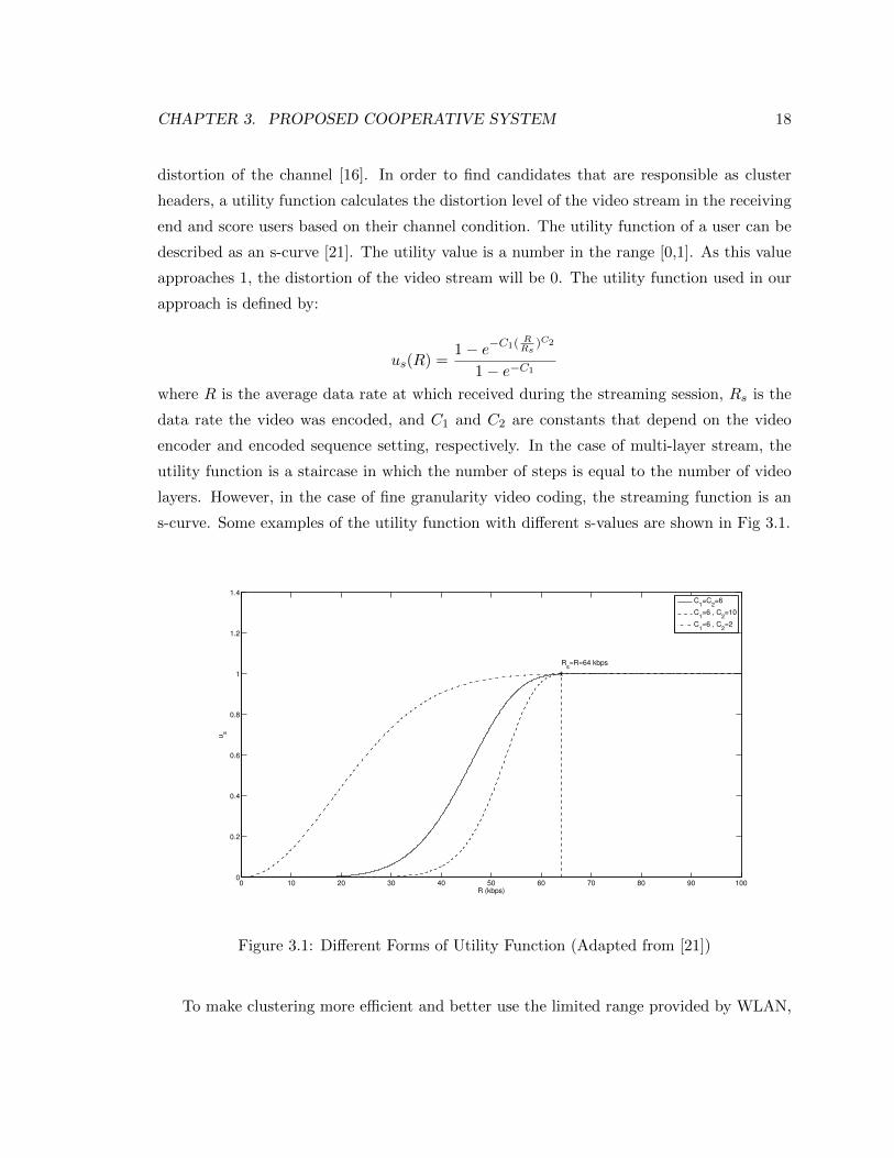
distortion of the channel [16]. In order to find candidates that are responsible as cluster
headers, a utility function calculates the distortion level of the video stream in the receiving
end and score users based on their channel condition. The utility function of a user can be
described as an s-curve [21]. The utility value is a number in the range [0,1]. As this value
approaches 1, the distortion of the video stream will be 0. The utility function used in our
approach is defined by:
us(R) =1− e−C1( R
Rs)C2
1− e−C1
where R is the average data rate at which received during the streaming session, Rs is the
data rate the video was encoded, and C1 and C2 are constants that depend on the video
encoder and encoded sequence setting, respectively. In the case of multi-layer stream, the
utility function is a staircase in which the number of steps is equal to the number of video
layers. However, in the case of fine granularity video coding, the streaming function is an
s-curve. Some examples of the utility function with different s-values are shown in Fig 3.1.
0 10 20 30 40 50 60 70 80 90 1000
0.2
0.4
0.6
0.8
1
1.2
1.4
R (kbps)
us
Rs=R=64 kbps
C1=C
2=6
C1=6 , C
2=10
C1=6 , C
2=2
Figure 3.1: Different Forms of Utility Function (Adapted from [21])
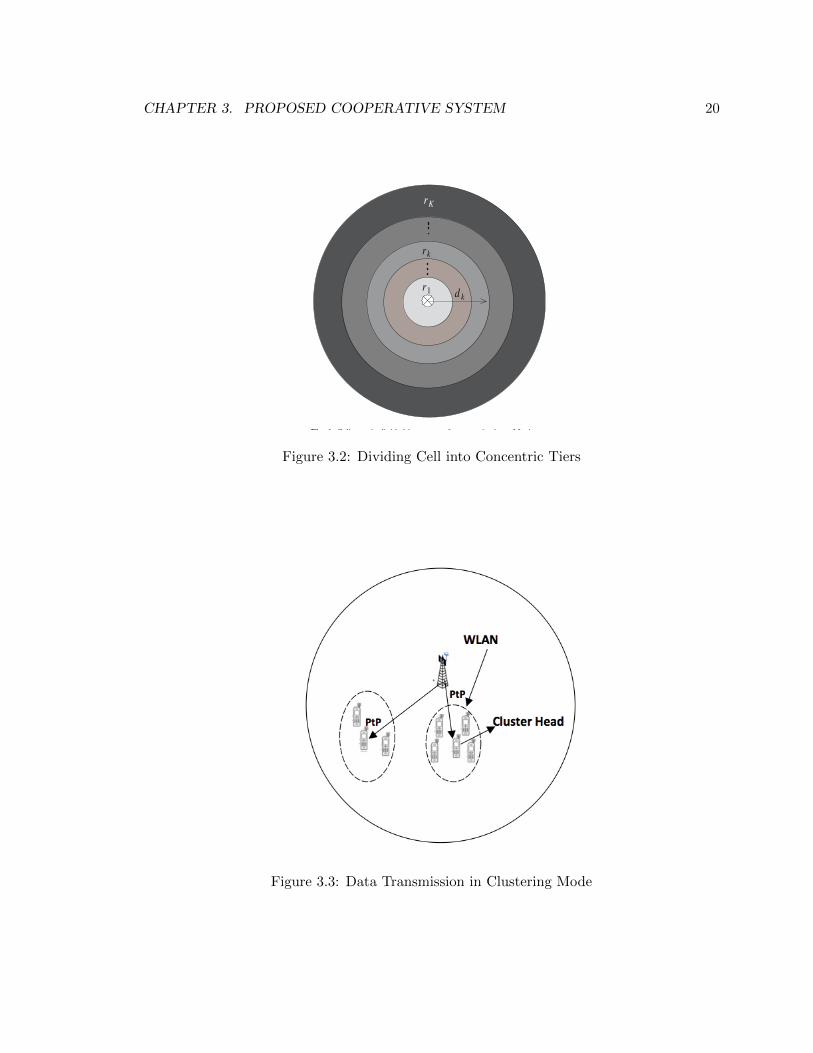
To make clustering more efficient and better use the limited range provided by WLAN,

CHAPTER 3. PROPOSED COOPERATIVE SYSTEM 19
the grouping process has two phases. The first phase happens statically before the data
transmission starts. The entire cell is divided into set of concentric tiers, as shown in Fig
3.2, and users in each tier will be considered as one group based on their distance from
the base station. Then users in each tier are partitioned into clusters in the second phase
of clustering. In each transmission time, the signal-to-noise ratio for each of the users is
computed based on the feedback that is sent to the base station. To find cluster headers
that are supposed to have better channel conditions, a utility function is defined that takes
channel feedback information as input and calculates the average received rate of each user.
Afterwards, users with higher utility value will be chosen as cluster headers and users in
their WLAN range will be considered to be a cluster. The process ends when each user
is either cluster header or belongs to a cluster. Fig 3.3 shows cooperation of nodes in
transmission of data.
Assume there are N users 1, 2, · · · , N in the cell which are divided into M concentric
tiers. Let R be the radius of the cell.
Tier(j) ={j|djb > R× j/M and djb < R× (j + 1)/M
},
where djb is the distance from user j to the base station. This is the first phase of the
clustering. The algorithm for computing each Tier(j) is given in Algorithm 1.
The utility function used in the clustering phase is defined by:
ui(R) =1− e−6( R
Rs)6
1− e−6.
After utility values are computed, the user with the maximum value among the users
in tier Tier(j), chj , and will be the cluster header. Let r be the communication range of a
mobile user, users of Tier(j) that are within distance r from chj form a cluster:
G(chj) ={k|k uncovered, |dkb − d
chj
b | < r}.
The algorithm for the second phase of clustering is given in Algorithm 2.
To ensure the fairness of our approach, cluster header selection follows a round robin
scheme. User i is assigned a number n(i) that specifies how many times that user has been
selected as a cluster header. Users that are not selected as cluster header are given priority.
If all users have been previously selected, n(i) becomes zero and selection is based only on
utility values.
CHAPTER 3. PROPOSED COOPERATIVE SYSTEM 20
r1
rk
rK
d k
Fig. 1 Cell area is divided into a set of concentric rings. Maximum
Figure 3.2: Dividing Cell into Concentric Tiers
Figure 3.3: Data Transmission in Clustering Mode

CHAPTER 3. PROPOSED COOPERATIVE SYSTEM 21
Algorithm 1 First Phase of Clustering
for i = 1 to N do
for j = 0 to M do
Compute dib for node i
if dib ≥ R× j/M and dib < R× (j + 1)/M then
Add User i to Tier(j)
end if
end for
end for
Algorithm 2 Second Phase of Clustering
for i = 1 to M do
repeat
for k in {users of Tier(j)} do
Set Max Zero
Compute u(k)
if max < u(k) then
max = u(k)
chi = k
end if
end for
for k in {users of Tier(j) } do
if |dkb − dchj
b | < r then
Add k to G(chj)
end if
end for
until All nodes are marked
end for
We use the cooperation protocol proposed by Liu, et. al [8, 9] for data relay within
a cluster using WLAN. With the cluster headers chosen, they receive bursts from eNB.
Then each cluster header broadcasts a message to all the users in its range and announces
that devices should receive data from it. A time-out is set in case the users don’t receive

CHAPTER 3. PROPOSED COOPERATIVE SYSTEM 22
bursts within a certain amount of time. The cluster header in the failed cluster should go
through an updating process. After receiving the burst, the cluster headers turn off their
LTE interface and broadcast data using only WLAN. After sending, they go to WLAN idle
state to save energy. This protocol also handles network dynamics for joining and leaving
the cooperative system.
3.2 Scheduling Algorithm
In each transmission slot, packet scheduler should assign resource blocks to users based
on a scheduling criteria. One of the goals of scheduling algorithms is to allocate radio
resources to users to maximize quality of service for all the users. They aim to maximize
throughput while being fair. Two well known scheduling algorithms that meet these criteria
are Proportional Fair (PF) and Maximum Rate scheduler [7].
Channel-aware scheduling has been used in LTE networks where users send channel
quality information to eNB periodically. CQI feedback is sent by user via uplink control
messages and eNB decides how to assign resource blocks to users based on this feedback
information [7, 25]. Channel-sensitive scheduling is challenging in multimedia services due
to delay constraints on the feedback information arrival.
In our simulations, we have used two different scheduling algorithms. The first is PF [7]
which is used for allocation of resources in unicast mode when clustering is applied. The
second is Max-Sum multicast scheduler [16, 26] and is used for scheduling resource blocks
for multicast groups. In the following, a detailed description of these algorithms is provided.
In PF, at the beginning of each transmission slot, eNB downlink scheduler selects all
flows that have to be scheduled in the MAC layer. A flow is chosen at this moment only
if it has data to transmit and the receiver is not in idle state. The scheduler computes a
scheduling metric for user i and subchannel j and then chooses the flow with the highest
metric to schedule for each subchannel. The process has the following steps:
In the first step, eNB creates a list of flows that has to be scheduled for the subframe.
For each flow, CQI feedback is stored and MAC queue length that shows the amount of data
to transmit. The scheduling metric is then computed. The PF scheduler metric considers
channel quality experienced by each user and also past user throughput. The goal of the
PF scheduler is to maximize throughput, while providing fairness among users. The metric
used is based on the available data rate and average past data rate. The weight of flow i in
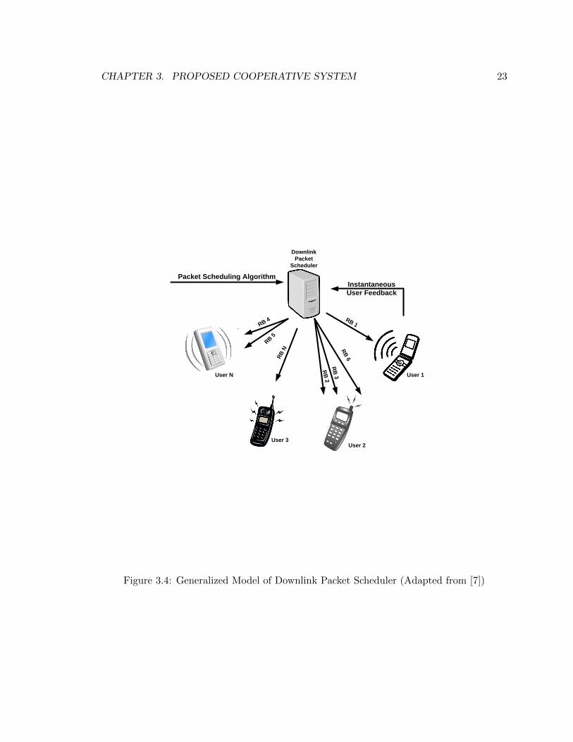
CHAPTER 3. PROPOSED COOPERATIVE SYSTEM 23
Packet Scheduling AlgorithmInstantaneous
User Feedback
Downlink
Packet
Scheduler
User 1
User 2User 3
User N
RB 1
RB
6
RB
3
RB
2
RB
N
RB 4
RB 5
Figure 3.4: Generalized Model of Downlink Packet Scheduler (Adapted from [7])

CHAPTER 3. PROPOSED COOPERATIVE SYSTEM 24
the subchannel j is computed by
Wij = rij/Ri.
The value rij is calculated based on the user feedback that is sent to eNB for subchannel
j periodically. The average transmission rate Ri is computed by:
Ri(t) =
(1− 1
tc
)×Ri (t− 1) +
1
tc× ri (t− 1)
where tc is time window of appropriate size. This window size is a tradeoff between user
satisfaction and throughput maximization.
The eNB assigns subchannel j to the user with the highest metric. The size of transport
block to be transmitted is then computed based on mapping the CQI index to MCS index
and number of assigned subchannels to the flow.
Max-Sum scheduler is an extension of the PF scheduler and is proposed for LTE and
HSDPA networks. Its objective is to maximize the product of users’ utilities within a
multicast group. The objective function of the scheduler is given by:
ϕ(n) =
M∏m=1
Sm∏S=1
u(m, s).
The scheduler decides multicast group, transmission rate, and MCS index in each trans-
mission slot. In order to make decisions, the scheduler should have channel feedback infor-
mation from users in each subcarrier periodically. It’s not possible for users to send feedback
information continuously. Therefore, users send SINR values of each subcarrier periodically
and eNB uses the average throughput of users in each Transmission Time Interval(TTI)
[16, 26]. The details of the Max-Sum scheduler are presented below [16, 26]:
In the first step, the scheduler decides the highest transmission rate and the best mod-
ulation coding scheme for each multicast group. The transmission rate for each group and
each layer of the video stream in time slot n is calculated by:
RMCS = PRBfull rate ×OFDM symbol per subframe× bit per symbol× code rate.
In this step, MCS index is the maximum value of
CHAPTER 3. PROPOSED COOPERATIVE SYSTEM 25
MCS∗k,n(m) = argmax1≤MCSindex≤15
{Sm∑S=1
ukn(m, s) ·RMCS
}.
The second step selects the layer of the video stream that maximizes the product of
users’ utilities per multicast group.
kn(m)∗ = argmax1≤k≤L
{Sm∑s=1
ukn(m, s) ·RMCS∗
}.
The final step is choosing the multicast group that has the highest product of user utility
values with the transmission rate and video layer decided in previous steps.
m∗n = argmax1≤m≤M
{Sm∑s=1
uk∗
n (m, s) ·RMCS∗
}.
The Max-Sum algorithm is designed for scalable video transmission but in our approach the
video stream is not layered.
3.3 Base Station Power Setting
In cellular networks, power control mechanisms are applied to increase network capacity and
coverage while maximizing output signal power and decreasing power consumption. These
strategies are used for the base station power setting in the downlink and for mobile station
power control in the uplink.
In LTE, there is open and closed loop power control for the uplink. In open loop power
control, the mobile station sets the power level of the signal based on the power of the noise
and the desired level of SINR for the received signal. Closed loop power control uses the
power level computed by the open loop power control as an input and adjusts the power
level of the signal based on the path loss experienced by each user. However, there is no
power control for the downlink in LTE and the base station uses its maximum power to
guarantee the quality of the signal at the receiving end [27].
There are two different ways to set the power of subchannels in the downlink. In the
conventional method, fixed power is set for the base station and divided equally among
subchannels without considering channel quality information. In the waterfilling method,
more power is allocated to subchannels that have better channel quality; therefore, the sum
of the data rates of the subchannels is maximized. The power allocated to each subchannel

CHAPTER 3. PROPOSED COOPERATIVE SYSTEM 26
is related to the data rate. The data rate is related to signal-to-noise ratio logarithmically
based on the Shannon capacity formula given by (3.1) [28].
data-rate :=1
2× (1 + logSNR). (3.1)
The problem is then formulated as:
Rmax =N∑i=1
M∑j=1
wijRij
subject toN∑i=1
pi < Ptotal
where wik is the binary channel allocation index of user i and subcarrier k satisfying wik ∈{0, 1} and wik ≤ 1. wik is 1 if subcarrier k is fully occupied by user i or 0 otherwise. Ptotal
is the maximum power at the transmitter in the downlink.
In our approach, there is no fixed power setting for the base station. In each TTI, power
is assigned to subchannels based on the CQI feedback received from users. Certain quality
of the received signal is set for all users in terms of SINRtarget. Transmission power is
then computed by calculating interference and pathloss for the specified channel realization
model. The power of the base station is then set to be the sum of the values set for the
subchannels. The formula for the power computation for each subchannel is given by:
SINRtarget = Preceivednoise+interference ,
Ptransmission = Preceived ∗ PropagationLoss(rb),
Ptransmission(rbi) = SINRtarget + noise + interference− PropagationLoss(rbi)|db format
subject to :
N∑1
power(rbi) < max-power of BS.
The advantage of setting the power dynamically is that since the power is set based
on specific quality requirements of the user, it guarantees receiver signal quality and also
decreases power consumption of the base station.
Chapter 4
Simulation
In this chapter, we provide numerical results showing that the proposed cooperative system
outperforms previous non-cooperative schedulers in average power consumption and average
delay. First, parameters used in the simulation and simulation methodology are described.
Then experimental results are presented. Finally, results are analyzed based on the theory
provided in the previous chapters.
4.1 Simulation Procedure
To simulate the scenarios in the LTE network, we have used an open-source simulator called
LTE-Sim 2.1. LTE-Sim is an open source C++ simulator that simulates different aspects
of LTE’s main elements. LTE-Sim simulates QoS management, single cell/multicell sce-
narios, multiuser environment, handover, frequency reuse techniques, and user mobility. It
also implements well-known scheduling algorithms including Proportional Fair and Modi-
fied Largest Weighted Delay First, and Exponential Proportional Fair. Moreover, in the
application layer different traffic generators are implemented including trace-based, VoIP,
constant bit rate, and variable bit rate. Simulation of multicast sessions needs some mod-
ification in different layers of the LTE protocol stack. In the application layer, we have
implemented the MBMS traffic in point-to-multipoint mode. In the MAC layer, two sched-
ulers are added: One is used in the clustering mechanism and the other supports resource
allocation in point-to-multipoint transmission mode. For the point-to-point mode, we have
used Proportional Fair scheduler provided by LTE-Sim. In addition, eNB power setting is
done in the physical layer. The power values are computed in the MAC layer and are passed
27

CHAPTER 4. SIMULATION 28
to eNB’s physical channel so that the power values for each subchannel are set in each TTI.
In the clustering mechanism simulation, the receiving end should only receive packets when
it’s a cluster header, otherwise it is called a WLAN node. Therefore, the physical layer of
the receiving end has been changed. Due to the complexities of the LTE network simulation,
the simulation of the WLAN part is skipped in our evaluation.
Before the simulation starts, the first phase of clustering is applied and users are divided
into tiers based on their distance from the base station. Considering the IEEE 802.11n
coverage range and the radius of the cell, the number of tiers in the simulation is assumed
to be M = 5. In the MBMS traffic generator, a radio bearer is assigned to users of each
tier. Then the MBMS data transmitter starts the downlink scheduler.
In each TTI, radio bearers that have data to transmit are added to the list of the
scheduler. The second phase of clustering is then applied for all the radio bearers in the list.
To that aim, utility values of all the users in the radio bearers are computed and the user
with the maximum value is chosen to be the cluster header. After the clustering phase is
done, resource allocation starts. The scheduling metric is computed for each of the cluster
headers and resource blocks are assigned to the user with the highest metric. Afterwards,
the data rate, modulation coding scheme and transport block size are calculated to start
data transmission. For each cluster header, the CQI feedback of the allocated resource
blocks is mapped to the SINR values based on table 4.1 and effective SINR is computed
using formula 4.1. Then, SINR values are mapped to MCS index and transport block
size is calculated using the MCS index and the number of resource blocks assigned to the
cluster header flow. Before transmission starts, the values of downlink power for each of
the subchannels are computed. As discussed in the previous chapter, the power values for
each resource block are computed using the SINR values of the cluster head assigned to
that block, the path loss experienced by the user, noise and interference experienced in that
block. This transport block size is sent to the RLC layer which is set in unacknowledged
mode to compute packet size. The power values are also passed to the physical layer for
when the transmission signal starts sending the packets.
SINReffective =
∑Nrbi=1 SINRi
Nrb(4.1)
On the receiving end, users send their CQI feedback using full-band periodic reporting
mode, with the reporting interval set to 1ms. Whenever a user receives a signal, it first

CHAPTER 4. SIMULATION 29
Table 4.1: CQI TO SINR MAPPING
CQI Level SINR(db)
1 -4.632 -2.63 -0.124 2.265 4.736 7.537 8.678 11.329 14.2410 15.2113 18.6314 28.4915 34.6
checks to see if it’s a cluster header. If not, it forwards the packet, otherwise it computes
SINR of the received signal. If the measured SINR is less than the SINR target, the user
drops the packet, otherwise, it will receive the packet.
4.2 Simulation Parameters
This section includes the description of the parameters used in our simulation.
SINR Calculation: SINR value for the received signal of the i-th user in the j-th
subchannel is computed by:
SINRij =PRXij
FN0B + I
where PRXij is the receiving power of the i-th user in the j-th subchannel, F is the noise
figure (with default value 2.5), N0 is the noise spectral density (with default value −174db),
B is the bandwidth of the resource block (180MB) and I is the interference. The interference
is the total power of eNBs sharing the same frequency.
CHAPTER 4. SIMULATION 30
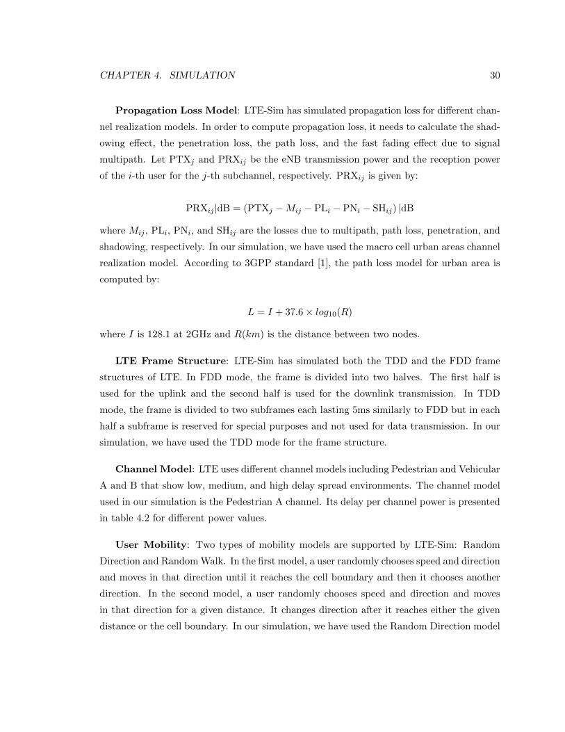
Propagation Loss Model: LTE-Sim has simulated propagation loss for different chan-
nel realization models. In order to compute propagation loss, it needs to calculate the shad-
owing effect, the penetration loss, the path loss, and the fast fading effect due to signal
multipath. Let PTXj and PRXij be the eNB transmission power and the reception power
of the i-th user for the j-th subchannel, respectively. PRXij is given by:
PRXij |dB = (PTXj −Mij − PLi − PNi − SHij) |dB
where Mij , PLi, PNi, and SHij are the losses due to multipath, path loss, penetration, and
shadowing, respectively. In our simulation, we have used the macro cell urban areas channel
realization model. According to 3GPP standard [1], the path loss model for urban area is
computed by:
L = I + 37.6× log10(R)
where I is 128.1 at 2GHz and R(km) is the distance between two nodes.
LTE Frame Structure: LTE-Sim has simulated both the TDD and the FDD frame
structures of LTE. In FDD mode, the frame is divided into two halves. The first half is
used for the uplink and the second half is used for the downlink transmission. In TDD
mode, the frame is divided to two subframes each lasting 5ms similarly to FDD but in each
half a subframe is reserved for special purposes and not used for data transmission. In our
simulation, we have used the TDD mode for the frame structure.
Channel Model: LTE uses different channel models including Pedestrian and Vehicular
A and B that show low, medium, and high delay spread environments. The channel model
used in our simulation is the Pedestrian A channel. Its delay per channel power is presented
in table 4.2 for different power values.
User Mobility: Two types of mobility models are supported by LTE-Sim: Random
Direction and Random Walk. In the first model, a user randomly chooses speed and direction
and moves in that direction until it reaches the cell boundary and then it chooses another
direction. In the second model, a user randomly chooses speed and direction and moves
in that direction for a given distance. It changes direction after it reaches either the given
distance or the cell boundary. In our simulation, we have used the Random Direction model

CHAPTER 4. SIMULATION 31
Table 4.2: PEDESTRIAN A CHANNEL MODEL
Relative Delay(ns) Relative Power(db)
0 030 -170 -280 -3110 -8190 -17.2410 -20.8
that updates the user position in each TTI.
4.3 Simulation Scenario
To analyze the behavior of the clustering algorithm, different scenarios have been imple-
mented. In the first scenario, the clustered scheduling algorithm is applied and downlink
power is set so that it meets the quality constraints of each subchannel. In the second sce-
nario, point-to-multipoint mode of MBMS is simulated and Max-Sum scheduler is applied.
No power setting method is used in this scenario and the power of downlink is equally di-
vided between subchannels. In the last scenario, the point-to-point transmission mode of
the MBMS is simulated. The Proportional Fair scheduler is used and the power of downlink
is divided equality between subchannels without considering channel quality information.
The network topology is simulated as a multi-cell multiuser environment. It consists of
six hexagonal cells that form on the edges of a cell in the center and users are randomly
distributed in the central cell. The user mobility model is based on the models described in
Section 4.2.
Each simulation scenario takes 20ms to run. However, as each case is run for user
populations ranging from 1 to 100 users while averaging the result of 100 runs per user
population to eliminate the effect of randomness in user distribution, the entire simulation
takes a long time to run. Therefore, we have used a super computer to parallelize the
running script to obtain the results more quickly (approximately 0.1 required time in a PC
that has 2.7-GHz intel core with 4GB RAM). We have used Hermes cluster that is an IBM
iDataplex server with eight 2.67-GHz Xeon x5550 cores with 24 GB of RAM. Hermes has
82 nodes with each node having eight cores making 656 cores available. One job is assigned

CHAPTER 4. SIMULATION 32
to each node running three different simulation scenarios for a specific user population.
The parallelized script submitted each run of the simulation as a job to one of the cores of
Hermes. The total running time on the Hermes server was approximately 10 hours, which
includes the waiting time of the jobs in the queues.
Simulation setting are presented in Table 4.3.
Table 4.3: SIMULATION PARAMETERS
Parameters Value
Cellular Layout 7 hexagonal grid cells
Cell Radius 1 Km
Maximum BS Tx power 43 W
Background Noise -174 db
Channel Bandwidth 10MHz
Propagation Model Okumura Hata
SINR Target 5 db
Users Distribution Random Distribution
Wireless Range 100 m (802.11n)
Number of Tiers 5
4.4 Experimental Results and Analysis
To evaluate the performance of our cooperative approach, two metrics are used: average
downlink power and average delay of packets during the simulation time. The data col-
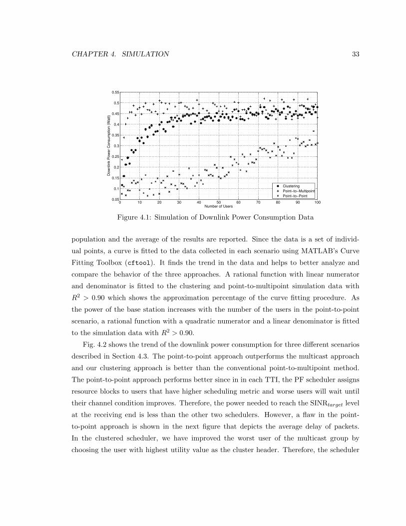
lected as a result of the simulation is presented in Fig. 4.1. This data is dependent on the
distribution of the users in the cell, which affects the clustering procedure, and users’ dis-
tance from the base station. After finding the cluster header, the number of users forming
a cluster depends on users’ distribution. The distance of users also has an impact on their
channel condition and the utility value of users will differ in different scenarios. To achieve
reliable results and control these parameters, in each simulation run the users’ location is
fixed for the point-to-point, point-to-multipoint, and clustering approaches. To eliminate
the influence of random user distribution, each simulation is run 100 times for each user
CHAPTER 4. SIMULATION 33
0 10 20 30 40 50 60 70 80 90 1000.05
0.1
0.15
0.2
0.25
0.3
0.35
0.4
0.45
0.5
0.55
Dow
nlin
k P
ow
er
Consum
ption (
Watt)
Number of Users
Clustering
Point−to−Multipoint
Point−to−Point
Figure 4.1: Simulation of Downlink Power Consumption Data
population and the average of the results are reported. Since the data is a set of individ-
ual points, a curve is fitted to the data collected in each scenario using MATLAB’s Curve
Fitting Toolbox (cftool). It finds the trend in the data and helps to better analyze and
compare the behavior of the three approaches. A rational function with linear numerator
and denominator is fitted to the clustering and point-to-multipoint simulation data with
R2 > 0.90 which shows the approximation percentage of the curve fitting procedure. As
the power of the base station increases with the number of the users in the point-to-point
scenario, a rational function with a quadratic numerator and a linear denominator is fitted
to the simulation data with R2 > 0.90.
Fig. 4.2 shows the trend of the downlink power consumption for three different scenarios
described in Section 4.3. The point-to-point approach outperforms the multicast approach
and our clustering approach is better than the conventional point-to-multipoint method.
The point-to-point approach performs better since in in each TTI, the PF scheduler assigns
resource blocks to users that have higher scheduling metric and worse users will wait until
their channel condition improves. Therefore, the power needed to reach the SINRtarget level
at the receiving end is less than the other two schedulers. However, a flaw in the point-
to-point approach is shown in the next figure that depicts the average delay of packets.
In the clustered scheduler, we have improved the worst user of the multicast group by
choosing the user with highest utility value as the cluster header. Therefore, the scheduler

CHAPTER 4. SIMULATION 34
0 10 20 30 40 50 60 70 80 90 1000.05
0.1
0.15
0.2
0.25
0.3
0.35
0.4
0.45
0.5
NUMBER OF USERS
PO
WE
R O
F B
AS
S S
TA
TIO
N (
W)
Clustering Approach
PTM Approach
PTP Approach
Figure 4.2: Average Downlink Power Consumption
is responsible to allocate the resources to cluster headers that have better channel quality
and the power needed for downlink transmission to achieve SINRtarget is decreased compared
to the conventional point-to-multipoint approach. Fig. 4.2 shows that our approach saves
the downlink power of eNB about 25% on average for a user population of less than 20,
about 15% on average for a user population between 20 and 50, and about 5% on average
for a user population between 50 and 100. As the number of users grows, the cooperative
mechanism leads to less power saving. This is mainly because a larger number of users call
for more cluster headers which makes each of the cluster headers less likely to be able to
improve the channel condition of the multicast group. Therefore, power consumption of the
downlink is improved less in larger user groups. Both approaches behave logarithmically
and achieve a maximum bound as the number of users increases while the point-to-point
approach grows linearly as number of the users increases.
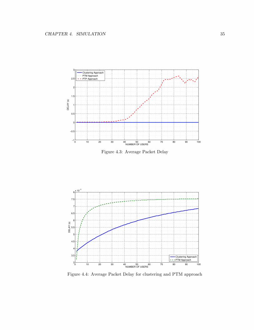
Fig. 4.3 shows the trend of the average delay during the simulation time for each of the
scenarios. The delay of clustering and point-to-multipoint approach is negligible compared
to point-to-point delay. Fig. 4.4 compares the average delay of the clustering approach to
that of the point-to-multipoint approach and shows that delay decreases in the clustering
approach. This is because the number of users served by an eNB is decreased which means
there are more resources available for cluster headers. Therefore, data rate and transport
block size is increased and delay is decreased.
CHAPTER 4. SIMULATION 35
0 10 20 30 40 50 60 70 80 90 100−1
−0.5
0
0.5
1
1.5
2
2.5
3
NUMBER OF USERS
DE
LA
Y (
s)
Clustering Approach
PTM Approach
PTP Approach
Figure 4.3: Average Packet Delay
0 10 20 30 40 50 60 70 80 90 1003
3.5
4
4.5
5
5.5
6
6.5
7
7.5
8x 10
−3
NUMBER OF USERS
DE
LA
Y (
s)
Clustering Approach
PTM Approach
Figure 4.4: Average Packet Delay for clustering and PTM approach

CHAPTER 4. SIMULATION 36
In the cooperative approach, users act as WiFi routers while connecting to the LTE
network. Therefore, battery drainage of the mobile station is a critical issue that has to
be investigated. Liu, et al. presented numerical results that shows cooperation benefits
both mobile users and the base station in WMAN [8, 9]. They have used idle and connected
modes to switch between WLAN and WMAN interfaces in transfer intervals and make users
sleep, when there is no data transfer.
Keshav, et al. proposed a power saving mechanism similar to Liu, et al. [8, 9] that
takes care of the issue arises in coordination of LTE and WLAN [10]. LTE has power
control mechanisms in the uplink that saves the battery of users significantly using connected
discontinuous reception (DRX) strategies. WiFi also has many power saving strategies.
Therefore, in order for these networks to cooperate efficiently, these power saving strategies
must be combined.
Keshav, et al. have used two mechanisms of power saving. First, whenever there is no
data transmission interfaces go to sleep and wake up only to receive paging or incoming
information. The second mechanism is to find the DRX pattern of the LTE and let mobile
users go to sleep whenever there is a gap in the data transfer. Their approach offers a power
saving mechanism for the users in cooperative LTE/WLAN networks and solves high power
consumption of users while cooperating [10].

Chapter 5
Conclusion and Future Work
Cooperation of wireless networks improves capacity, performance, and coverage of these
networks. In this thesis, we have studied a cooperation scheme of the LTE and WLAN
networks and investigated its benefit in reducing power consumption of the downlink channel
in LTE networks while previous research show that cooperation saves battery of the mobile
users. In the following, a summary of the contributions of this thesis and some future work
in this direction are presented.
5.1 Contribution Summary
In this thesis, we have proposed a mechanism for cooperation of LTE and WLAN networks.
A clustering algorithm is devised to group users into clusters. A power setting mechanism
is also presented to set transmission power of downlink subchannels based on the required
quality of service at the end users. Moreover, some modules are added to an open source
simulator called “LTE-Sim” to simulate the clustering scenario and evaluate average power
consumption of the downlink channel in clustered, point-to-point, and point-to-multipoint
transmission modes. Results of the simulations show that our approach consumes less
power than a conventional point-to-multipoint transmission mechanism. The point-to-point
approach outperforms our approach and uses less downlink power. To compare the per-
formance of our approach, we have measured average packet delay in each transmission.
Results show that the average delay is not acceptable for large numbers of users in point-
to-point transmission mode. Therefore, clustering algorithm performs more efficiently in
multimedia applications that are delay sensitive.
37

CHAPTER 5. CONCLUSION AND FUTURE WORK 38
5.2 Future Work
Our research has fully investigated the cooperation of LTE and WLAN networks. How-
ever, there are still many aspects that have to be considered to benefit from cooperation
mechanisms.
The WLAN simulation of mobile users in the proposed mechanism is an interesting topic.
Simulating the IEEE 802.11n WLAN protocol in multicast transmission mode will give a
more precise evaluation of performance metrics of the proposed cooperative system.
New modules have to be added to LTE-Sim, so that mobile users can send data to each
other.
Studying battery life improvement mechanisms for mobile users in our cooperative mech-
anism is also a valuable research topic.
This thesis focuses on cooperation in single cell point-to-multipoint mode. The single
frequency network mode of MBMS that reduces SINR significantly should be investigated.
Bibliography
[1] 3GPP TS 25.346 V8.0.0. Introduction of the Multimedia Broadcast Multicast Service(MBMS) in the Radio Access Network (RAN), 2008. http://www.quintillion.co.jp/
3GPP/Specs/25346-800.pdf.
[2] FreeScale SemiConductor. Long Term Evolution Protocol Overview, 2008. http://www.freescale.com/files/wireless_comm/doc/white_paper/LTEPTCLOVWWP.pdf.
[3] A. Alexiou, C. Bouras, and V. Kokkinos. An Enhanced MBMS Power Control Mecha-nism Towards Long Term Evolution, June 2009.
[4] E. Karipidis, N.D. Sidiropoulos, and Z. Luo. Quality of Service and Max-min FairTransmit Beamforming to Multiple Co-channel Multicast Groups. IEEE Trans. SignalProcessing, pages 1268–1279, 2008.
[5] E. Karipidis, N. Sidiropoulos, and L. Tassiulas. Joint QoS Multicast Power / AdmissionControl and Base Station Assignment : A Geometric Programming Approach. InProceedings of the 5th IEEE Workshop on Sensor Array and Multi-Channel SignalProcessing (SAM), pages 155–159, 2008.
[6] Umer Salim and Dirk T M Slock. Average Minimum Transmit Power to Achieve SINRTargets: Performance Comparison of Various User Selection Algorithms. EURASIPJournal on Wireless Communications and Networking, Dec. 2011.
[7] H.A.M. Ramli, R. Basukala, K. Sandrasegaran, and R. Patachaianand. Performanceof Well Known Packet Scheduling Algorithms in the Downlink 3GPP LTE System. InProceedings of the IEEE 9th International Conference on Communications (MICC),pages 815–820, Dec. 2009.
[8] Y. Liu and M. Hefeeda. Video Streaming over Cooperative Wireless Networks. InProceedings of the ACM Multimedia Systems (MMSys), pages 99–110, 2 2010.
[9] Y. Liu, C.H. Hsu, and M. Hefeeda. On the Benefits of Cooperative Video Broadcastover WMANs and WLANs. In Proceedings of the ACM Multimedia, pages 901–904,2009.
39

BIBLIOGRAPHY 40
[10] K. Keshav, V.R. Indukuri, and P. Venkataram. Energy Efficient Scheduling in 4G SmartPhones for Mobile Hotspot Applications. In Proceedings of the National Conference onCommunications (NCC), Feb. 2012.
[11] A. Ghosh, J. Zhang, J. G. Andrews, and R. Muhamed. Fundamentals of LTE. PrenticeHall, 1st edition, Oct. 2010.
[12] H. Holma and A. Toskala. LTE for UMTS: Evolution to LTE-Advanced. Wiley, 2ndedition, May 2011.
[13] T. Ali-Yahiya. Understanding LTE and its Performance. Springer, 1st edition, July2011.
[14] Jyrki T. J. Penttinen, editor. The LTE / SAE Deployment Handbook. Wiley, 1stedition, Jan. 2012.
[15] M. Rupp, S. Caban, C. Mehlfhrer, and M. Wrulich. Evaluation of HSDPA and LTE:From Testbed Measurements to System Level Performance. Wiley, 1st edition, Feb.2012.
[16] H. Barzegar. Multicast Scheduling for Streaming Video in Single Frequency Networks.Master’s thesis, Royal Institute of Technology, 2011.
[17] A. Ghosh and R. Ratasuk. Essentials of LTE and LTE-A. Cambridge University Press,1st edition, Sep. 2011.
[18] K. Ravi and M. A. Hussain. 4G Mobile Broadband- LTE Network Architecture andProtocol Stack. International Journal of Research and Reviews in Ad-hoc Networks, 1,March 2011.
[19] Y. Xiao and Y. Pan. Emerging Wireless LANs, Wireless PANs, and Wireless MANs:IEEE 802.11, IEEE 802.15, 802.16 Wireless Standard Family. Wiley Publishing, 1stedition, 2009.
[20] S. Lu, Y. Cai, L. Zhang, J. Li, P. Skov, C. Wang, and Z. He. Channel-Aware Fre-quency Domain Packet Scheduling for MBMS in LTE. In Proceedings of the 69th IEEEVehicular Technology Conference(VTC) , pages 26–29, April 2009.
[21] V. Vukadinovic and G. Karlsson. Multicast Scheduling with Resource Fairness Con-straints. ACM/Springer Wireless Networks, 15(5):571–583, July 2009.
[22] J. Lee, J. M. Lee, S.G. Choi, and J. Choi. Adaptive Scheduling Scheme for MulticastService in Multiuser OFDM Systems, May 2011.
[23] J .Liu, W. Chen, Z. Cao, Y.J. Zhang, and S.C. Liew. Utility-based User Grouping andBandwidth Allocation for Wireless Multicast Systems. In Proceedings of the IEEEInternational Conference on Communications (ICC09), pages 3930–3934, 2009.

BIBLIOGRAPHY 41
[24] S. G. Quan, J. Xu, and Y. Y. Kim. Utility-based Rate Allocation Scheme for MobileVideo Streaming over Femtocell Networks. Journal of Information Processing Sys-tems(JIPS), 5(3):151–158, 2009.
[25] G. Piro, L.A. Grieco, G. Boggia, F. Capozzi, and P. Camarda. Simulating LTE CellularSystems: An Open-Source Framework. IEEE Transactions on Vehicular Technology,60(2):498–513, Feb. 2011.
[26] V. Vukadinovic and G. Dan. Multicast Scheduling for Scalable Video Streaming inWireless Networks. In Proceedings of the first annual ACM SIGMM Conference onMultimedia Systems, pages 77–88. ACM, 2010.
[27] A. Simonsson and A. Furuskar. Uplink Power Control in LTE - Overview and Per-formance, Subtitle: Principles and Benefits of Utilizing rather than Compensating forSINR Variations. In Proceedings of the IEEE 68th Vehicular Technology Conference(VTC), June 2008.
[28] T. Peng, W. Wang, Q. Lu, and W. Wang. Subcarrier Allocation Based on Water-FillingLevel in OFDMA-Based Cognitive Radio Networks. In Proceedings of the InternationalConference on Wireless Communications, Networking and Mobile Computing(WiCom),June 2007.
[29] L. Song and J. Shen, editors. Evolved Cellular Network Planning and Optimization forUMTS and LTE. CRC Press, 1st edition, August 2010.
[30] E. Dahlman, A. Furuskr, Y. Jading, M. Lindstrm, and S. Parkvall. Key Featuresof the LTE Radio Interface. Erickson Review No.2, 2008. http://www.ericsson.com/
ericsson/corpinfo/publications/review/2008_02/files/6_LTE.pdf.