Embed Size (px)
Citation preview
Energy Conservation
in
Induction furnace
Programme on
Energy Conservation in Foundry Industry
E Nand Gopal The Energy and Resources Institute
11th August2014
Contents
Introduction and working principle
Losses in induction furnace
Energy conservation measures
Selection and sizing
Best operating practices
Case Studies 2
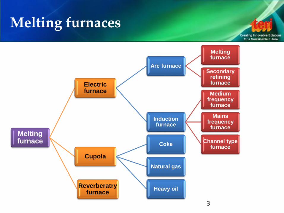
Melting furnaces
Melting furnace
Electric furnace
Arc furnace
Melting furnace
Secondary refining furnace
Induction furnace
Medium frequency
furnace
Mains frequency
furnace
Channel type furnace
Cupola
Coke
Natural gas
Heavy oil Reverberatry
furnace
3
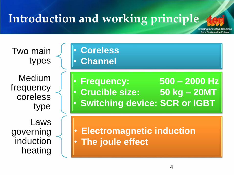
Introduction and working principle
Two main types
• Coreless
• Channel
Medium frequency
coreless type
• Frequency: 500 – 2000 Hz
• Crucible size: 50 kg – 20MT
• Switching device: SCR or IGBT
Laws governing induction
heating
• Electromagnetic induction
• The joule effect
4
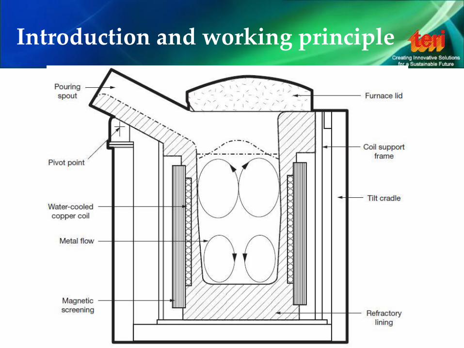
Introduction and working principle
5
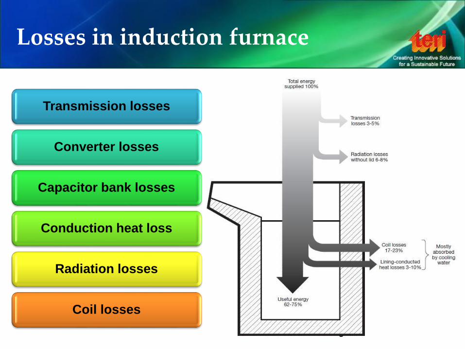
Losses in induction furnace
6
Transmission losses
Converter losses
Capacitor bank losses
Conduction heat loss
Radiation losses
Coil losses
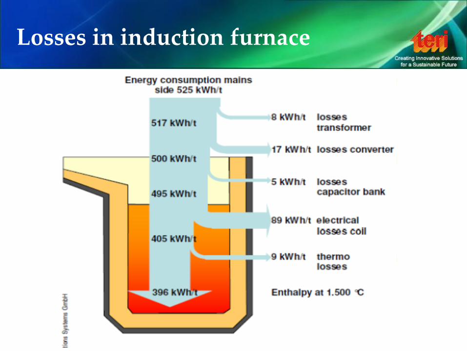
Losses in induction furnace
7
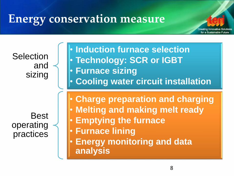
Energy conservation measure
Selection and
sizing
• Induction furnace selection
• Technology: SCR or IGBT
• Furnace sizing
• Cooling water circuit installation
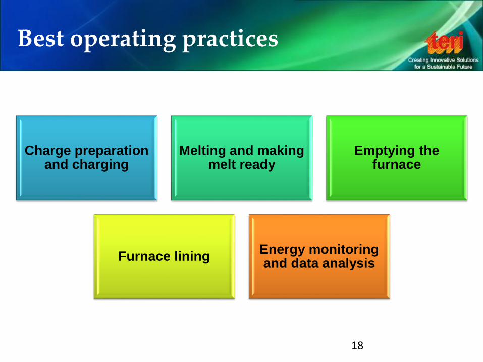
Best operating practices
• Charge preparation and charging
• Melting and making melt ready
• Emptying the furnace
• Furnace lining
• Energy monitoring and data analysis
8
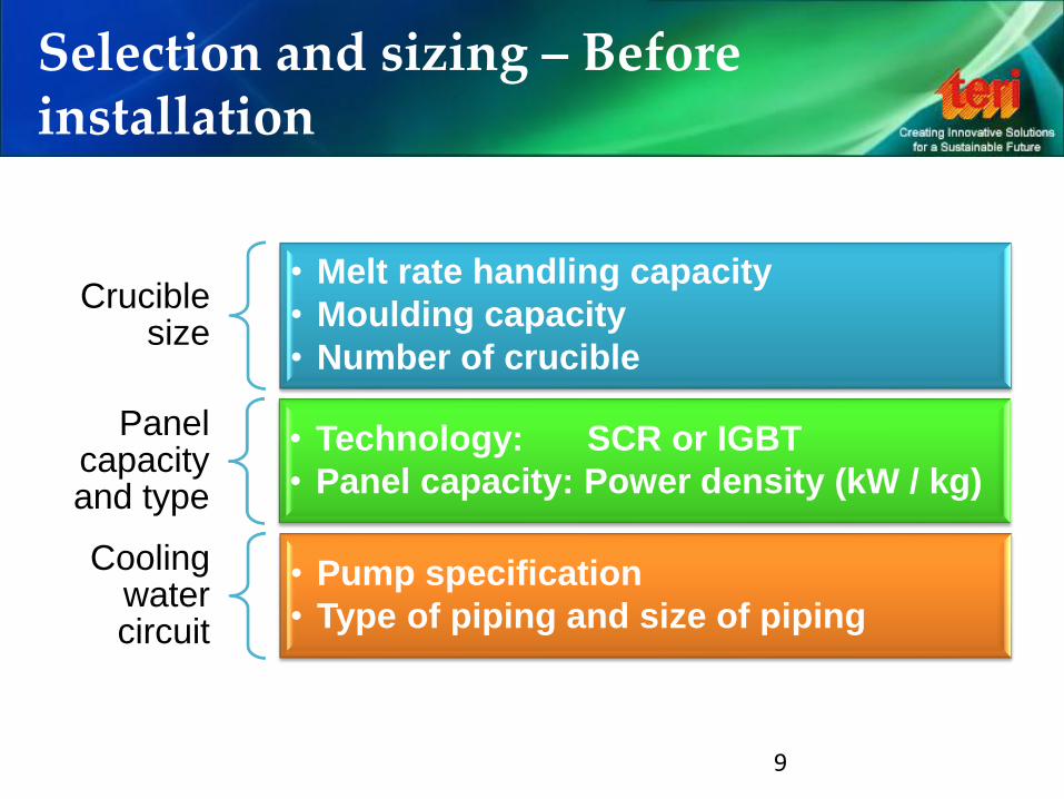
Selection and sizing – Before installation
9
Crucible size
• Melt rate handling capacity
• Moulding capacity
• Number of crucible
Panel capacity and type
• Technology: SCR or IGBT
• Panel capacity: Power density (kW / kg)
Cooling water circuit
• Pump specification
• Type of piping and size of piping
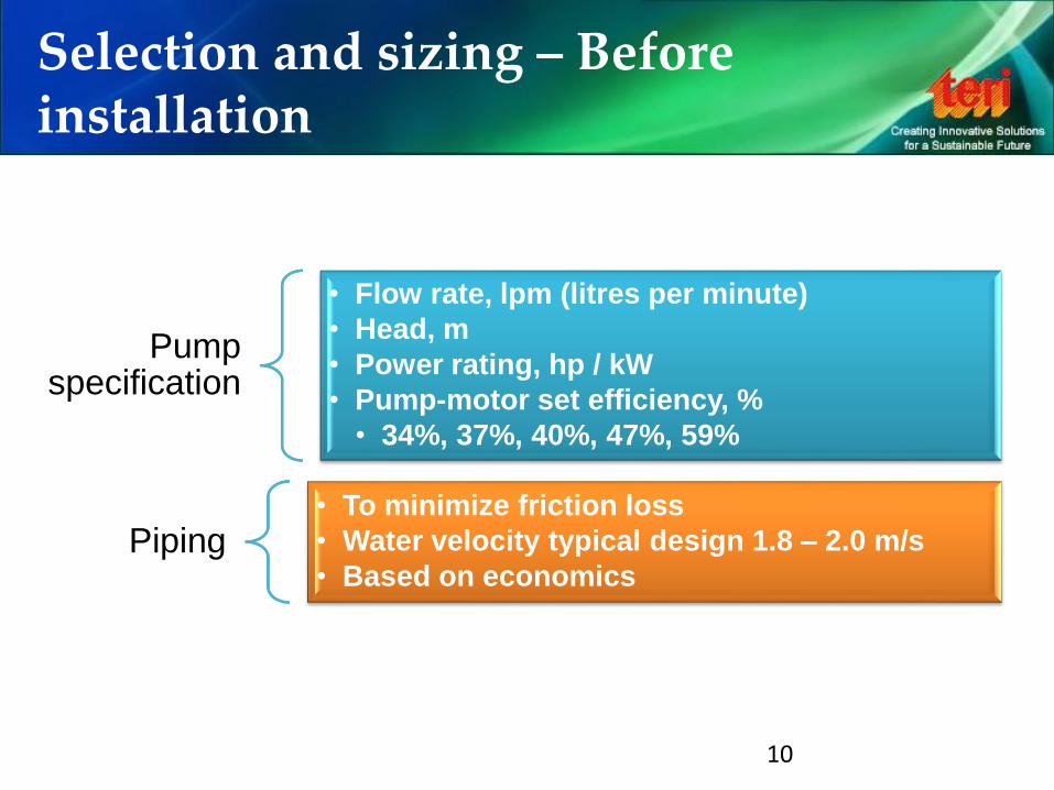
Selection and sizing – Before installation
10
Pump specification
• Flow rate, lpm (litres per minute)
• Head, m
• Power rating, hp / kW
• Pump-motor set efficiency, %
• 34%, 37%, 40%, 47%, 59%
Piping • To minimize friction loss
• Water velocity typical design 1.8 – 2.0 m/s
• Based on economics
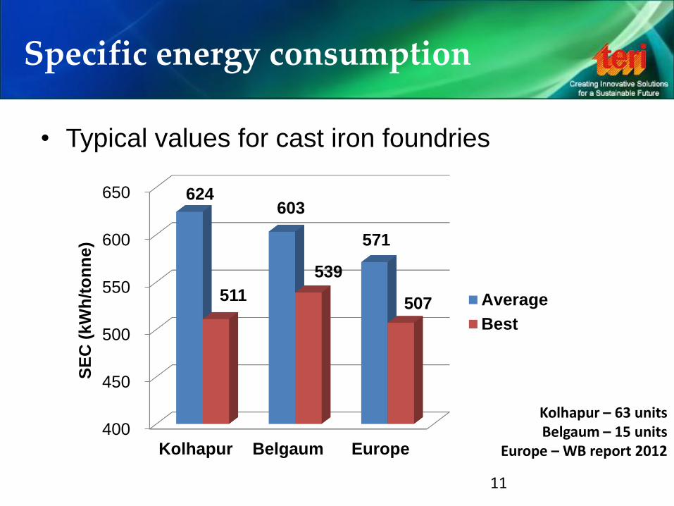
Specific energy consumption
11
• Typical values for cast iron foundries
400
450
500
550
600
650
Kolhapur Belgaum Europe
624 603
571
511
539
507
SE
C (
kW
h/t
on
ne)
Average
Best
Kolhapur – 63 units Belgaum – 15 units
Europe – WB report 2012

Analysis – Power Curve
12
0
100
200
300
400
500
600
Po
we
r, k
W
Induction furnace power curve
Delay in
spectro
analysis
0
50
100
150
200
250
300
350
400
450
500
1:0
5:0
0 P
M
1:0
7:0
0 P
M
1:0
9:0
0 P
M
1:1
1:0
0 P
M
1:1
3:0
0 P
M
1:1
5:0
0 P
M
1:1
7:0
0 P
M
1:1
9:0
0 P
M
1:2
1:0
0 P
M
1:2
3:0
0 P
M
1:2
5:0
0 P
M
1:2
7:0
0 P
M
1:2
9:0
0 P
M
1:3
1:0
0 P
M
1:3
3:0
0 P
M
1:3
5:0
0 P
M
1:3
7:0
0 P
M
1:3
9:0
0 P
M
1:4
1:0
0 P
M
1:4
3:0
0 P
M
1:4
5:0
0 P
M
1:4
7:0
0 P
M
1:4
9:0
0 P
M
1:5
1:0
0 P
M
1:5
3:0
0 P
M
1:5
5:0
0 P
M
1:5
7:0
0 P
M
1:5
9:0
0 P
M
2:0
1:0
0 P
M
2:0
3:0
0 P
M
2:0
5:0
0 P
M
2:0
7:0
0 P
M
Po
we
r, k
W
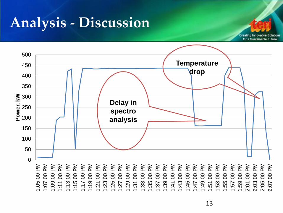
Analysis - Discussion
13
Delay in
spectro
analysis
Temperature
drop
Analysis - Discussion
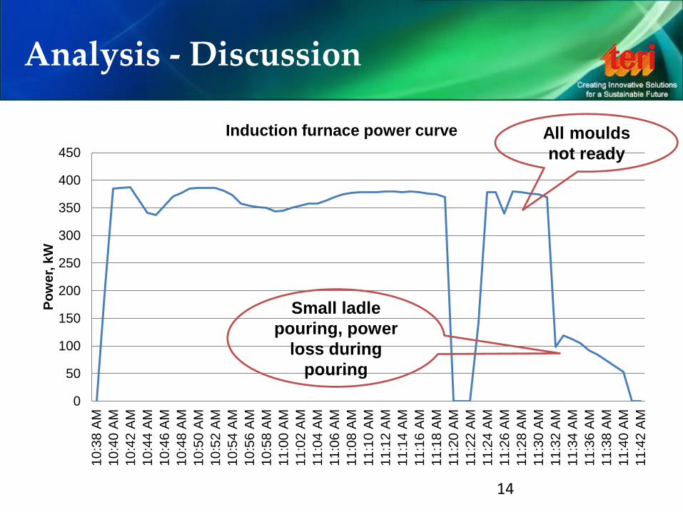
14
0
50
100
150
200
250
300
350
400
450
10
:38
AM
10
:40
AM
10
:42
AM
10
:44
AM
10
:46
AM
10:4
8 A
M
10
:50
AM
10
:52
AM
10
:54
AM
10
:56
AM
10
:58
AM
11
:00
AM
11:0
2 A
M
11
:04
AM
11
:06
AM
11
:08
AM
11
:10
AM
11
:12
AM
11
:14
AM
11
:16
AM
11
:18
AM
11
:20
AM
11
:22
AM
11
:24
AM
11
:26
AM
11
:28
AM
11
:30
AM
11
:32
AM
11
:34
AM
11
:36
AM
11
:38
AM
11
:40
AM
11
:42
AM
Po
we
r, k
W
Induction furnace power curve All moulds
not ready
Small ladle
pouring, power
loss during
pouring
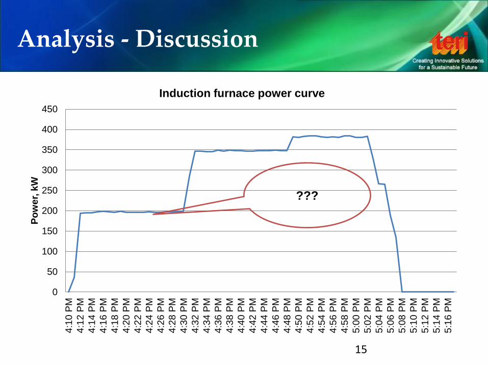
Analysis - Discussion
15
0
50
100
150
200
250
300
350
400
450
4:1
0 P
M
4:1
2 P
M
4:1
4 P
M
4:1
6 P
M
4:1
8 P
M
4:2
0 P
M
4:2
2 P
M
4:2
4 P
M
4:2
6 P
M
4:2
8 P
M
4:3
0 P
M
4:3
2 P
M
4:3
4 P
M
4:3
6 P
M
4:3
8 P
M
4:4
0 P
M
4:4
2 P
M
4:4
4 P
M
4:4
6 P
M
4:4
8 P
M
4:5
0 P
M
4:5
2 P
M
4:5
4 P
M
4:5
6 P
M
4:5
8 P
M
5:0
0 P
M
5:0
2 P
M
5:0
4 P
M
5:0
6 P
M
5:0
8 P
M
5:1
0 P
M
5:1
2 P
M
5:1
4 P
M
5:1
6 P
M
Po
we
r, k
W
Induction furnace power curve
???
0
200
400
600
800
1000
1200
1400
1600
1800
2000
10
:02
:00
AM
10:0
8:0
0 A
M
10
:14
:00
AM
10
:20
:00
AM
10
:26
:00
AM
10
:32
:00
AM
10:3
8:0
0 A
M
10
:44
:00
AM
10
:50
:00
AM
10
:56
:00
AM
11
:02
:00
AM
11
:08
:00
AM
11
:14
:00
AM
11
:20
:00
AM
11
:26
:00
AM
11
:32
:00
AM
11
:38
:00
AM
11
:44
:00
AM
11
:50
:00
AM
11
:56
:00
AM
12
:02
:00
PM
12
:08
:00
PM
12
:14
:00
PM
12
:20
:00
PM
12
:26
:00
PM
12
:32
:00
PM
12
:38
:00
PM
12
:44
:00
PM
12
:50
:00
PM
12
:56
:00
PM
1:0
2:0
0 P
M
1:0
8:0
0 P
M
1:1
4:0
0 P
M
Po
we
r, k
W
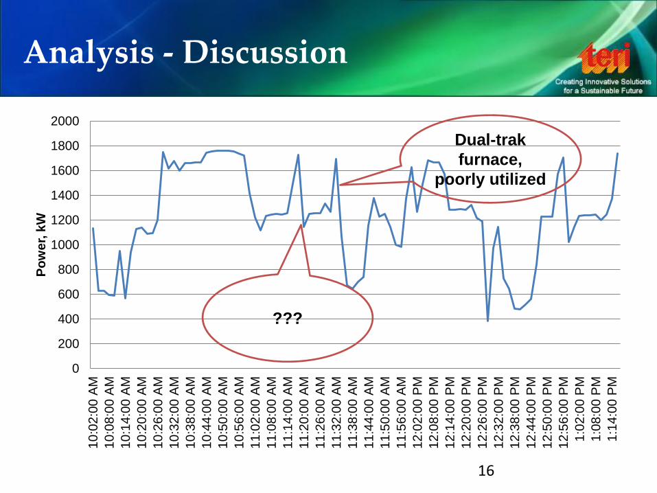
Analysis - Discussion
16
???
Dual-trak
furnace,
poorly utilized
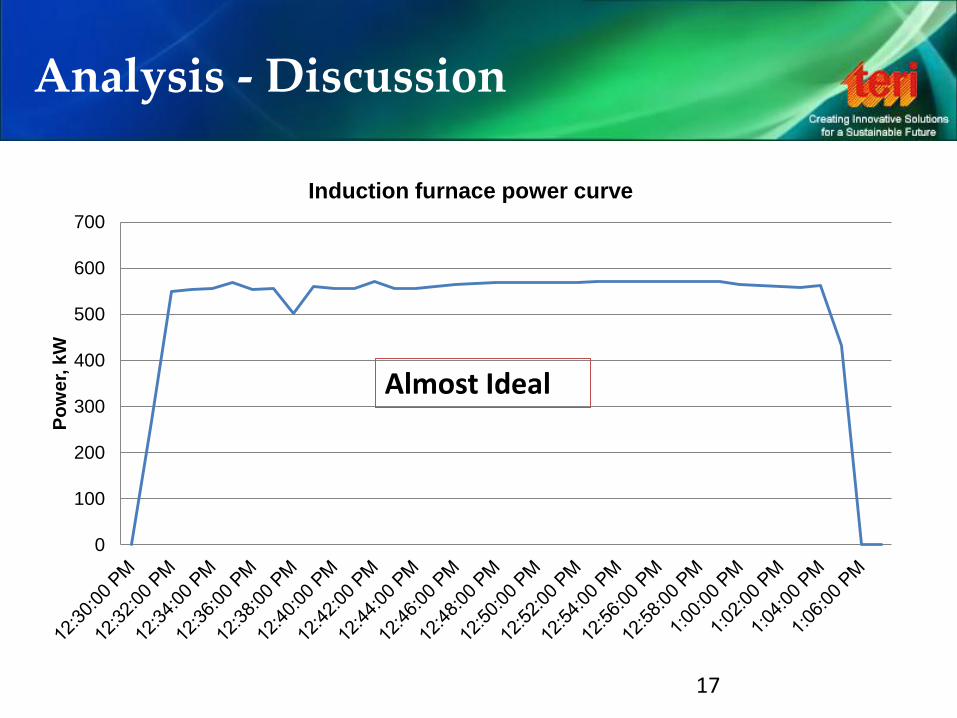
Analysis - Discussion
17
0
100
200
300
400
500
600
700
Po
we
r, k
W
Induction furnace power curve
Almost Ideal
Best operating practices
Charge preparation and charging
Melting and making melt ready
Emptying the furnace
Furnace lining Energy monitoring and data analysis
18
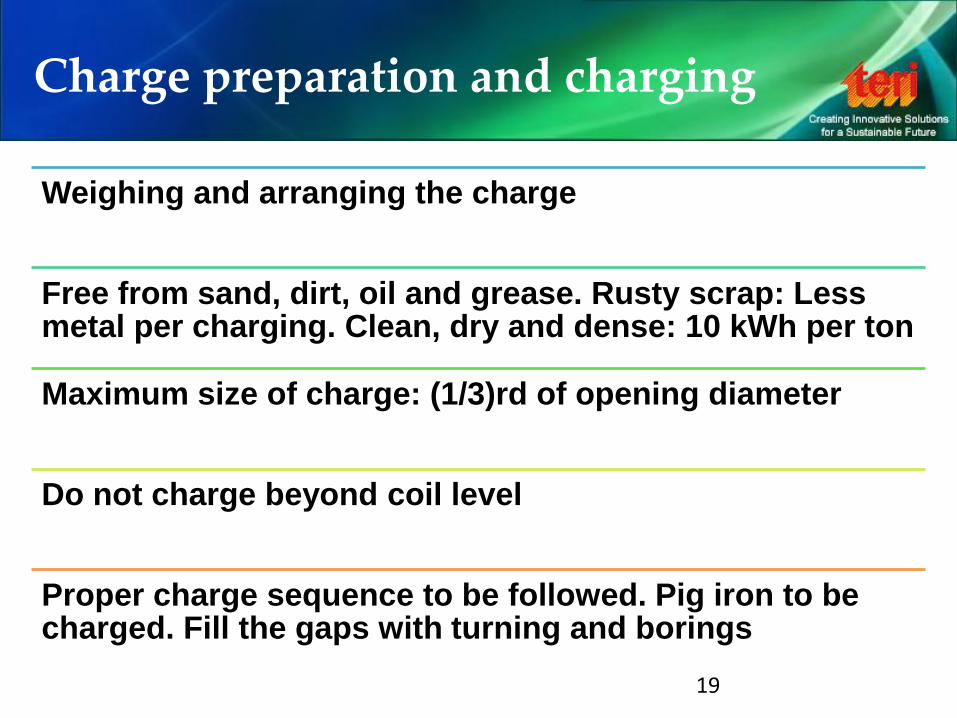
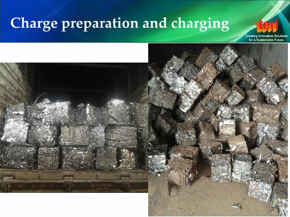
Charge preparation and charging
Weighing and arranging the charge
Free from sand, dirt, oil and grease. Rusty scrap: Less metal per charging. Clean, dry and dense: 10 kWh per ton
Maximum size of charge: (1/3)rd of opening diameter
Do not charge beyond coil level
Proper charge sequence to be followed. Pig iron to be charged. Fill the gaps with turning and borings
19
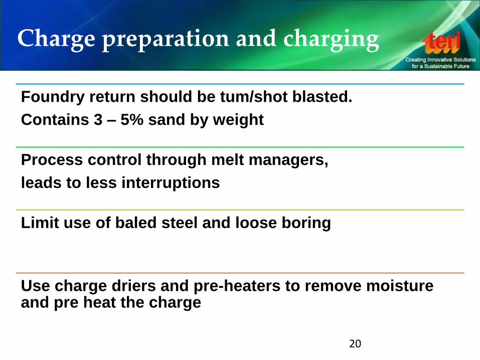
Charge preparation and charging
Foundry return should be tum/shot blasted.
Contains 3 – 5% sand by weight
Process control through melt managers,
leads to less interruptions
Limit use of baled steel and loose boring
Use charge driers and pre-heaters to remove moisture and pre heat the charge
20
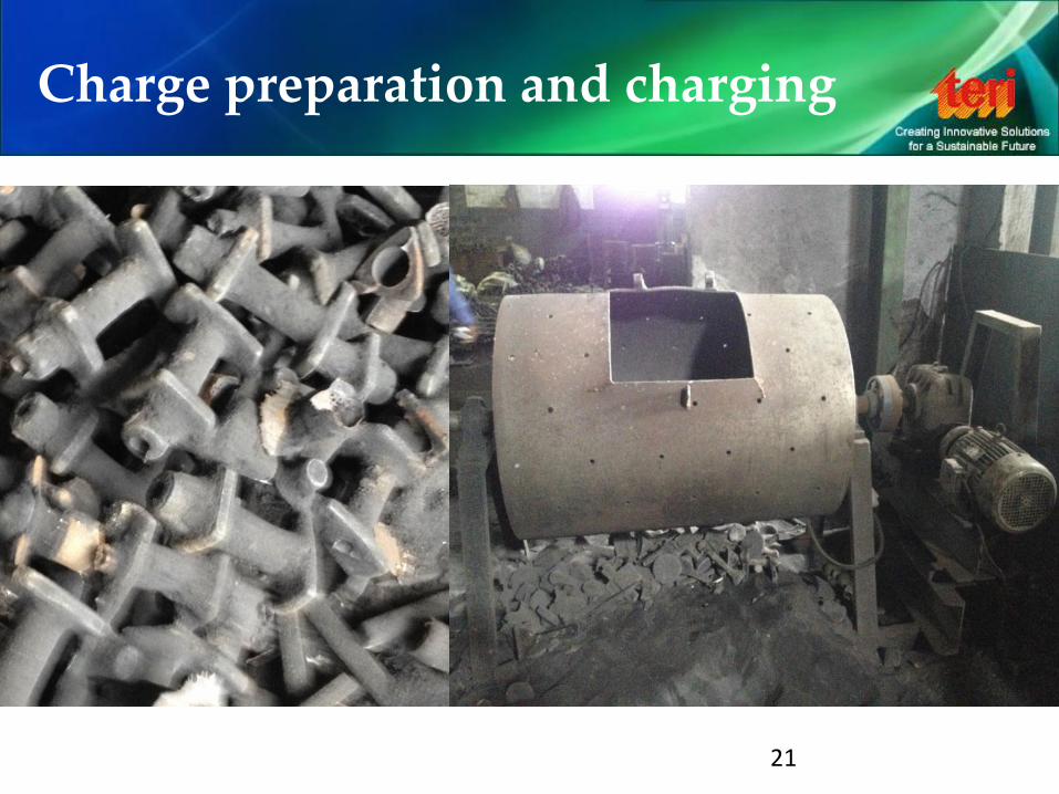
Charge preparation and charging
21
Charge preparation and charging
22
Melting and making melt ready
Follow melt process, always run furnace at full power
Use lid mechanism, 5 – 8 % energy lost through radiation
Typically 20 – 30 kWh per tonne saving using lid
Avoid build-up of slag on furnace walls
Proper tools and techniques should be used for de-slagging
Spectro-testing lab must be located near to melt shop
Avoid un-necessary super-heating of metal. 50 °C leads to more than 25 kWh per tonne
23
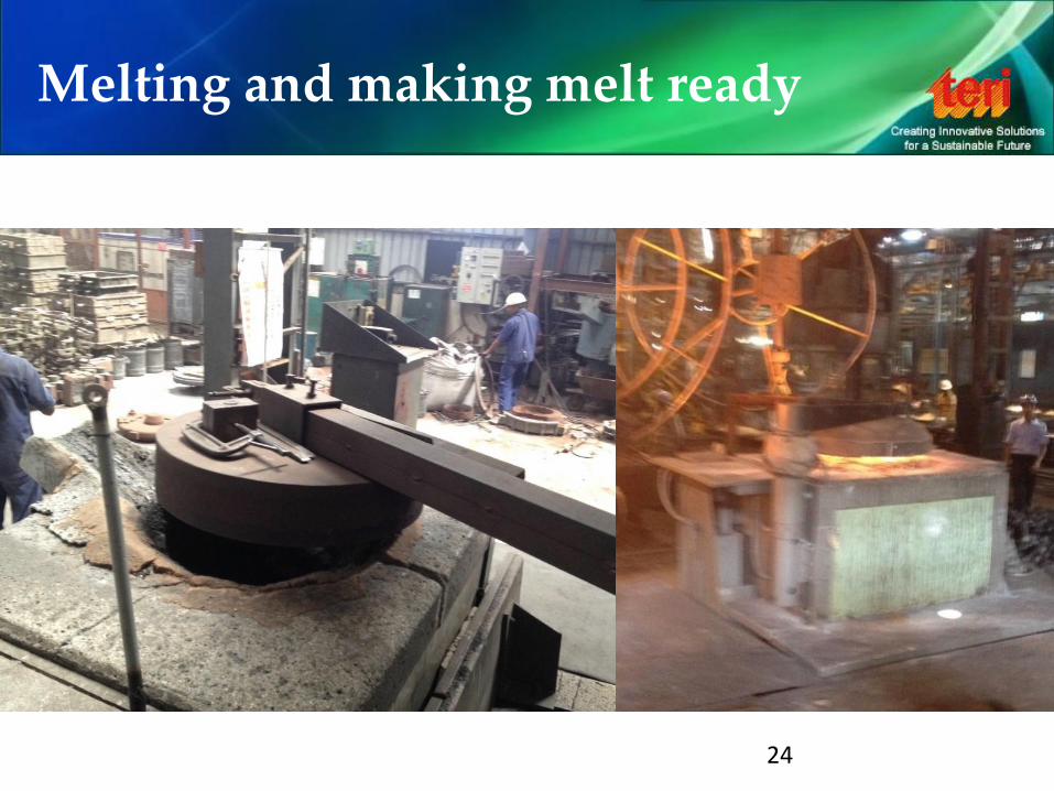
Melting and making melt ready
24
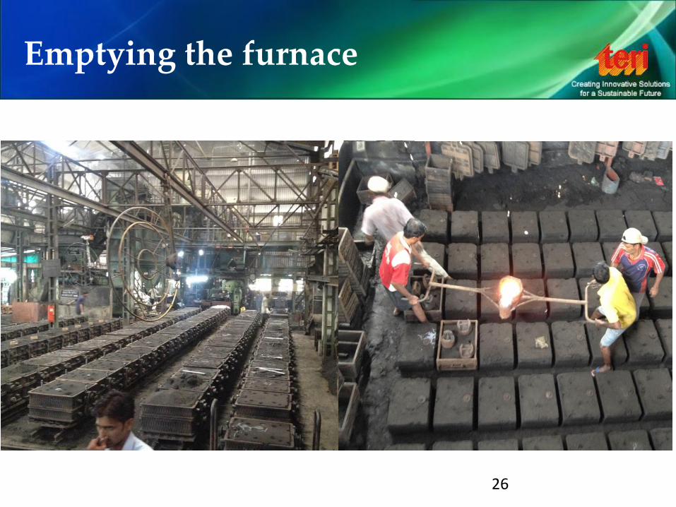
Emptying the furnace
Optimization of the ladle size to minimize the heat losses and empty the furnace in the shortest time
Optimization of the ladle transportation
Plan melting according to moulding. Metal should never wait for mould rather mould should be ready before metal
Use of ladle pre-heater. Proper positioning of burner is important to get uniform heating
Quantity of liquid metal returned to furnace must be as low as possible
Glass-wool or ceramic-wool cover for pouring ladle
Minimize plant breakdown by implementing a planned maintenance schedule
25
Emptying the furnace
26
Furnace lining
Select the correct lining material
Do not increase lining thickness at bottom or sidewalls. Increase in lining means reducing capacity of furnace
Do not allow furnace to cool very slow. Forced air cooling helps in developing cracks of lower depth, this helps in faster cold start cycle
Cold start cycle time should be ideally not more than 120% of normal cycle time
Coil cement should be smooth, in straight line and having thickness of 3 to 5 mm
While performing lining ensure that each layer is not more than 50mm. Compaction is better with smaller layer
Monitor lining performance
27
Energy monitoring and data analysis
Separate energy meter for furnace must be installed
Monitor energy consumtion on heat by heat basis
Analyse them in correlation with production data to arrive at specific energy consumption of furnace on daily basis
Any peak or valley in data must be studied and investigated
28
ENERGY MONITORING is the first step for achieving ENERGY SAVING

Be the change you want to see in the world
E Nand Gopal
+91 99715 17752