Embed Size (px)
Citation preview
ETSI EN 301 428 V1.3.1 (2006-02)
Candidate Harmonized European Standard (Telecommunications series)
Satellite Earth Stations and Systems (SES);Harmonized EN for Very Small Aperture Terminal (VSAT);
Transmit-only, transmit/receive or receive-only satellite earth stations operating in the 11/12/14 GHz frequency bands
covering essential requirements under article 3.2 of the R&TTE directive

ETSI
ETSI EN 301 428 V1.3.1 (2006-02) 2
Reference REN/SES-00270
Keywords regulation, satellite, VSAT
ETSI
650 Route des Lucioles F-06921 Sophia Antipolis Cedex - FRANCE
Tel.: +33 4 92 94 42 00 Fax: +33 4 93 65 47 16
Siret N° 348 623 562 00017 - NAF 742 C
Association à but non lucratif enregistrée à la Sous-Préfecture de Grasse (06) N° 7803/88
Important notice
Individual copies of the present document can be downloaded from: http://www.etsi.org
The present document may be made available in more than one electronic version or in print. In any case of existing or perceived difference in contents between such versions, the reference version is the Portable Document Format (PDF).
In case of dispute, the reference shall be the printing on ETSI printers of the PDF version kept on a specific network drive within ETSI Secretariat.
Users of the present document should be aware that the document may be subject to revision or change of status. Information on the current status of this and other ETSI documents is available at
http://portal.etsi.org/tb/status/status.asp
If you find errors in the present document, please send your comment to one of the following services: http://portal.etsi.org/chaircor/ETSI_support.asp
Copyright Notification
No part may be reproduced except as authorized by written permission. The copyright and the foregoing restriction extend to reproduction in all media.
© European Telecommunications Standards Institute 2006.
All rights reserved.
DECTTM, PLUGTESTSTM and UMTSTM are Trade Marks of ETSI registered for the benefit of its Members. TIPHONTM and the TIPHON logo are Trade Marks currently being registered by ETSI for the benefit of its Members. 3GPPTM is a Trade Mark of ETSI registered for the benefit of its Members and of the 3GPP Organizational Partners.
ETSI
ETSI EN 301 428 V1.3.1 (2006-02) 3
Contents
Intellectual Property Rights ................................................................................................................................7
Foreword.............................................................................................................................................................7
Introduction ........................................................................................................................................................8
1 Scope ......................................................................................................................................................11
2 References ..............................................................................................................................................12
3 Definitions and abbreviations.................................................................................................................12 3.1 Definitions........................................................................................................................................................12 3.2 Abbreviations ...................................................................................................................................................14
4 Technical requirements specifications ...................................................................................................15 4.1 General .............................................................................................................................................................15 4.1.1 Environmental profile .................................................................................................................................15 4.1.2 Control and Monitoring Functions (CMF)..................................................................................................15 4.1.3 Operational configurations .........................................................................................................................15 4.1.4 Transmit VSAT states and radio states .......................................................................................................15 4.1.4.1 Definitions.............................................................................................................................................15 4.1.4.2 Class A CMF.........................................................................................................................................16 4.1.4.3 Class B CMF.........................................................................................................................................16 4.1.4.4 Radio states ...........................................................................................................................................16 4.2 Conformance requirements ..............................................................................................................................17 4.2.1 Off-axis spurious radiation .........................................................................................................................17 4.2.1.1 Justification ...........................................................................................................................................17 4.2.1.2 Specification..........................................................................................................................................17 4.2.1.2.1 Transmit VSAT ...............................................................................................................................17 4.2.1.2.2 Receive-only VSAT ........................................................................................................................18 4.2.1.3 Conformance tests.................................................................................................................................19 4.2.2 On-axis spurious radiation for transmit VSAT ...........................................................................................19 4.2.2.1 Justification ...........................................................................................................................................19 4.2.2.2 Specification..........................................................................................................................................19 4.2.2.2.1 Specification 1: "Carrier-on" radio state..........................................................................................19 4.2.2.2.2 Specification 2: "Carrier-off" and "Emissions disabled" radio states ..............................................19 4.2.2.3 Conformance tests.................................................................................................................................19 4.2.3 Off-axis e.i.r.p emission density within the band........................................................................................19 4.2.3.1 Justification ...........................................................................................................................................20 4.2.3.2 Specification..........................................................................................................................................20 4.2.3.3 Conformance tests.................................................................................................................................21 4.2.4 Carrier suppression .....................................................................................................................................21 4.2.4.1 Justification ...........................................................................................................................................21 4.2.4.2 Specification..........................................................................................................................................21 4.2.4.3 Conformance tests.................................................................................................................................21 4.2.5 Mechanical (antenna pointing) for transmit VSAT ....................................................................................22 4.2.5.1 Justification ...........................................................................................................................................22 4.2.5.2 Specification..........................................................................................................................................22 4.2.5.3 Conformance tests.................................................................................................................................22 4.2.6 Class A Control and Monitoring Functions ................................................................................................22 4.2.6.1 Control and Monitoring Functions (CMF)............................................................................................22 4.2.6.1.1 General ............................................................................................................................................22 4.2.6.1.2 CMF state transition diagram ..........................................................................................................22 4.2.6.1.3 Specification of states......................................................................................................................24 4.2.6.2 Control Channels (CC)..........................................................................................................................24 4.2.6.2.1 Justification .....................................................................................................................................24 4.2.6.2.2 Specification....................................................................................................................................25 4.2.6.2.3 Conformance tests ...........................................................................................................................25 4.2.6.3 Self monitoring functions......................................................................................................................25

ETSI
ETSI EN 301 428 V1.3.1 (2006-02) 4
4.2.6.3.1 General ............................................................................................................................................25 4.2.6.3.2 Processor monitoring.......................................................................................................................26 4.2.6.3.3 Transmit subsystem monitoring ......................................................................................................26 4.2.6.3.4 VSAT transmission validation.........................................................................................................26 4.2.6.4 Reception of commands from the CCMF .............................................................................................28 4.2.6.4.1 General ............................................................................................................................................28 4.2.6.4.2 Disable message ..............................................................................................................................28 4.2.6.4.3 Enable Message ...............................................................................................................................28 4.2.6.5 Power-on/Reset .....................................................................................................................................28 4.2.6.5.1 Justification .....................................................................................................................................28 4.2.6.5.2 Specification....................................................................................................................................28 4.2.6.5.3 Conformance tests ...........................................................................................................................29 4.2.7 Class B Control and Monitoring Functions ................................................................................................29 4.2.7.1 Processor monitoring ............................................................................................................................30 4.2.7.1.1 Justification .....................................................................................................................................30 4.2.7.1.2 Specification....................................................................................................................................30 4.2.7.1.3 Conformance tests ...........................................................................................................................30 4.2.7.2 Transmit subsystem monitoring ............................................................................................................30 4.2.7.2.1 Justification .....................................................................................................................................30 4.2.7.2.2 Specification....................................................................................................................................30 4.2.7.2.3 Conformance tests ...........................................................................................................................30 4.2.7.3 Power-on/Reset .....................................................................................................................................30 4.2.7.3.1 Justification .....................................................................................................................................30 4.2.7.3.2 Specification....................................................................................................................................30 4.2.7.3.3 Conformance tests ...........................................................................................................................31 4.2.7.4 Control Channel (CC) reception ...........................................................................................................31 4.2.7.4.1 Justification .....................................................................................................................................31 4.2.7.4.2 Specification....................................................................................................................................31 4.2.7.4.3 Conformance tests ...........................................................................................................................31 4.2.7.5 Network control commands ..................................................................................................................31 4.2.7.5.1 Justification .....................................................................................................................................31 4.2.7.5.2 Specification....................................................................................................................................31 4.2.7.5.3 Conformance test.............................................................................................................................31 4.2.7.6 Initial burst transmission .......................................................................................................................32 4.2.7.6.1 Justification .....................................................................................................................................32 4.2.7.6.2 Specification....................................................................................................................................32 4.2.7.6.3 Conformance tests ...........................................................................................................................32
5 Testing for compliance with technical requirements..............................................................................32 5.1 Environmental conditions for testing ...............................................................................................................32 5.2 Essential radio test suites..................................................................................................................................32
6 Test methods for the complete VSAT....................................................................................................32 6.1 General .............................................................................................................................................................32 6.2 Off-axis spurious radiation ...............................................................................................................................33 6.2.1 Test method ................................................................................................................................................33 6.2.1.0 Multi-carrier operation ..........................................................................................................................34 6.2.1.1 Up to 1 000 MHz ..................................................................................................................................34 6.2.1.1.1 Test site............................................................................................................................................34 6.2.1.1.2 Measuring receivers.........................................................................................................................34 6.2.1.1.3 Procedure.........................................................................................................................................35 6.2.1.2 Above 1 000 MHz.................................................................................................................................35 6.2.1.2.1 Identification of the significant frequencies of spurious radiation ..................................................35 6.2.1.2.2 Measurement of radiated power levels of identified spurious radiation ..........................................36 6.2.1.2.3 Measurement of conducted spurious radiation at the antenna flange ..............................................37 6.3 On-axis spurious radiation for transmit VSAT.................................................................................................38 6.3.1 Test method ................................................................................................................................................38 6.3.1.1 Test site .................................................................................................................................................38 6.3.1.2 Method of measurement........................................................................................................................38 6.3.1.2.1 General ............................................................................................................................................38 6.3.1.2.2 Method of measurement at the antenna flange ................................................................................38 6.3.1.2.3 Method of measurement with a test antenna ...................................................................................39
ETSI
ETSI EN 301 428 V1.3.1 (2006-02) 5
6.4 Off-axis e.i.r.p emission density within the band .............................................................................................40 6.4.1 Test method ................................................................................................................................................40 6.4.1.1 General ..................................................................................................................................................40 6.4.1.2 Transmit output power density..............................................................................................................40 6.4.1.2.1 General ............................................................................................................................................40 6.4.1.2.2 Test site............................................................................................................................................40 6.4.1.2.3 Method of measurement ..................................................................................................................41 6.4.1.3 Antenna transmit gain ...........................................................................................................................42 6.4.1.3.1 General ............................................................................................................................................42 6.4.1.3.2 Test site............................................................................................................................................42 6.4.1.3.3 Method of measurement ..................................................................................................................42 6.4.1.4 Antenna transmit radiation patterns ......................................................................................................43 6.4.1.4.1 General ............................................................................................................................................43 6.4.1.4.2 Test site............................................................................................................................................43 6.4.1.4.3 Test arrangement .............................................................................................................................43 6.4.1.4.4 Co-polar radiation pattern-azimuth..................................................................................................43 6.4.1.4.5 Co-polar radiation pattern-elevation................................................................................................44 6.4.1.4.6 Cross-polar radiation pattern-azimuth .............................................................................................45 6.4.1.4.7 Cross-polar radiation pattern-elevation ...........................................................................................45 6.4.2 Computation of results................................................................................................................................46 6.5 Carrier suppression...........................................................................................................................................46 6.5.1 Test method ................................................................................................................................................46 6.6 Antenna pointing for transmit VSAT ...............................................................................................................46 6.6.1 Test method ................................................................................................................................................46 6.7 Class A Control and Monitoring Functions......................................................................................................47 6.7.1 General........................................................................................................................................................47 6.7.2 Test arrangement ........................................................................................................................................47 6.7.3 Control Channels (CC) ...............................................................................................................................48 6.7.3.1 Test method...........................................................................................................................................48 6.7.3.1.1 Test method for internal CC ............................................................................................................48 6.7.3.1.2 Test method for external CC ...........................................................................................................49 6.7.4 Processor monitoring ..................................................................................................................................49 6.7.4.1 Test method...........................................................................................................................................49 6.7.5 Transmit subsystem monitoring..................................................................................................................49 6.7.5.1 Test method...........................................................................................................................................49 6.7.6 VSAT transmission validation....................................................................................................................50 6.7.6.1 Test method for VSAT validation by the CCMF for VSAT using internal CC ....................................50 6.7.6.2 Test method for VSAT validation by receiving station(s) for VSAT using internal CC.......................50 6.7.6.3 Test method for transmission validation for VSAT using external CC.................................................50 6.7.7 Reception of commands from the CCMF ...................................................................................................50 6.7.7.1 Test method...........................................................................................................................................50 6.7.8 Power-on/Reset...........................................................................................................................................50 6.7.8.1 Test method...........................................................................................................................................50 6.8 Class B Control and Monitoring Functions ......................................................................................................51 6.8.1 Test arrangement ........................................................................................................................................51 6.8.2 Processor monitoring- Test method ............................................................................................................52 6.8.3 Transmit subsystem monitoring-Test method.............................................................................................52 6.8.4 Power-on/Reset-Test method......................................................................................................................53 6.8.5 Control Channel (CC) reception-Test method ............................................................................................53 6.8.6 Network Control commands-Test method..................................................................................................54 6.8.7 Initial burst transmission-Test method........................................................................................................56
7 Test methods for modified VSAT ..........................................................................................................56 7.1 General .............................................................................................................................................................56 7.2 Antenna subsystem replacement ......................................................................................................................57
Annex A (normative): The EN Requirements table (EN-RT)..........................................................58
Annex B (informative): Pointing stability methodology .....................................................................59
Annex C (informative): The EN title in the official languages ...........................................................60
ETSI
ETSI EN 301 428 V1.3.1 (2006-02) 6
Annex D (informative): Bibliography...................................................................................................62
History ..............................................................................................................................................................63
ETSI
ETSI EN 301 428 V1.3.1 (2006-02) 7
Intellectual Property Rights IPRs essential or potentially essential to the present document may have been declared to ETSI. The information pertaining to these essential IPRs, if any, is publicly available for ETSI members and non-members, and can be found in ETSI SR 000 314: "Intellectual Property Rights (IPRs); Essential, or potentially Essential, IPRs notified to ETSI in respect of ETSI standards", which is available from the ETSI Secretariat. Latest updates are available on the ETSI Web server (http://webapp.etsi.org/IPR/home.asp).
Pursuant to the ETSI IPR Policy, no investigation, including IPR searches, has been carried out by ETSI. No guarantee can be given as to the existence of other IPRs not referenced in ETSI SR 000 314 (or the updates on the ETSI Web server) which are, or may be, or may become, essential to the present document.
Foreword This Candidate Harmonized European Standard (Telecommunications series) has been produced by ETSI Technical Committee Satellite Earth Stations and Systems (SES).
The present document has been produced by ETSI in response to a mandate from the European Commission issued under Directive 98/34/EC [3] (as amended) laying down a procedure for the provision of information in the field of technical standards and regulations.
The present document is intended to become a Harmonized Standard, the reference of which will be published in the Official Journal of the European Communities referencing the Directive 1999/5/EC [1] of the European Parliament and of the Council of 9 March 1999 on radio equipment and telecommunications terminal equipment and the mutual recognition of their conformity ("R&TTE Directive").
Technical specifications relevant to Directive 1999/5/EC [1] are given in annex A.
National transposition dates
Date of adoption of this EN: 10 February 2006
Date of latest announcement of this EN (doa): 31 May 2006
Date of latest publication of new National Standard or endorsement of this EN (dop/e):
30 November 2006
Date of withdrawal of any conflicting National Standard (dow): 30 November 2006

ETSI
ETSI EN 301 428 V1.3.1 (2006-02) 8
Introduction ETSI has designed a modular structure for the standards. Each standard is a module in the structure. The modular structure is shown in figure 1.
- If needed, new standards for human exposure to Electromagnetic Fields,
- if needed, new standards for acoustic safety
Use of spectrum
* If needed Scoped by equipment class or type
Scoped by frequency and/or equipment type
Disability*
Privacy*
Fraud*
No harm to the network*
Emergency*
Interworking via the network*
Interworking with the network
Non-radio Radio (RE)
Non-TTE TTE
3.1b
3.2
3.3c
3.3b
3.3a
3.3d
3.3e
3.3f
Radio Product EMC
EN 301 489 multi-part EMC standard
Generic and product standards also notified under EMC Directive
Standards also notified under LV Directive
3.1a
New radio harmonized standards Spectrum
EMC
Safety
Figure 1: Modular structure for the various standards used under the R&TTE Directive [1]
ETSI
ETSI EN 301 428 V1.3.1 (2006-02) 9
The left hand edge of the figure 1 shows the different clauses of Article 3 of the R&TTE Directive [1].
For article 3.3 various horizontal boxes are shown. Dotted lines indicate that at the time of publication of the present document essential requirements in these areas have to be adopted by the Commission. If such essential requirements are adopted, and as far and as long as they are applicable, they will justify individual standards whose scope is likely to be specified by function or interface type.
The vertical boxes show the standards under article 3.2 for the use of the radio spectrum by radio equipment. The scopes of these standards are specified either by frequency (normally in the case where frequency bands are harmonized) or by radio equipment type.
For article 3.1b the diagram shows EN 301 489, the multi-part product EMC standard for radio used under the EMC Directive.
For article 3.1a the diagram shows the existing safety standards currently used under the LV Directive and new standards covering human exposure to electromagnetic fields. New standards covering acoustic safety may also be required.
The bottom of the figure shows the relationship of the standards to radio equipment and telecommunications terminal equipment. A particular equipment may be radio equipment, telecommunications terminal equipment or both. A radio spectrum standard will apply if it is radio equipment. An article 3.3 standard will apply as well only if the relevant essential requirement under the R&TTE Directive is adopted by the Commission and if the equipment in question is covered by the scope of the corresponding standard. Thus, depending on the nature of the equipment, the essential requirements under the R&TTE Directive may be covered in a set of standards.
The modularity principle has been taken because:
- it minimizes the number of standards needed. Because equipment may, in fact, have multiple interfaces and functions it is not practicable to produce a single standard for each possible combination of functions that may occur in an equipment;
- it provides scope for standards to be added:
- under article 3.2 when new frequency bands are agreed; or
- under article 3.3 should the Commission take the necessary decisions
without requiring alteration of standards that are already published;
- it clarifies, simplifies and promotes the usage of Harmonized Standards as the relevant means of conformity assessment.
Remarks on the present document
The present document allows the choice of either a class A Control and Monitoring system or a class B Control and Monitoring system. The class B system is more suitable for networks comprising very many terminals.
The determination of the parameters of the user earth stations using a given geo-stationary satellite for the protection of the spectrum allocated to that satellite, is considered to be under the responsibility of the satellite operator or the satellite network operators. For this reason the requirement on the cross polarization discrimination which was in TBR 28 (see Bibliography) has not been copied in the present document and inter-modulation limits inside the band 14,0 GHz to 14,5 GHz are to be determined by system design and are subject to satellite operator specifications.
The requirements have been selected to ensure an adequate level of compatibility with other radio services. The levels, however, do not cover extreme cases which may occur in any location but with a low probability of occurrence.
The present document may not cover those cases where a potential source of interference which is producing individually repeated transient phenomena or a continuous phenomenon is present, e.g. a radar or broadcast site in the near vicinity. In such a case it may be necessary to use special protection applied to either the source of interference, or the interfered part or both.
The present document does not contain any requirement, recommendation or information about the installation of the VSAT.
ETSI
ETSI EN 301 428 V1.3.1 (2006-02) 10
All parts of the indoor unit related to reception, processing and presentation of the received information except the control channel are not within the scope of the present document. The syntax of the control channel messages is outside the scope of the present document.
ETSI
ETSI EN 301 428 V1.3.1 (2006-02) 11
1 Scope The present document applies to Very Small Aperture Terminals (VSATs) which have the following characteristics:
• The VSAT is operating in one or more frequency ranges in the part of the following bands allocated exclusively to the Fixed Satellite Services (FSS):
- 14,00 GHz to 14,25 GHz (earth-to-space);
- 12,50 GHz to 12,75 GHz (space-to-earth);
or in the shared parts of the following bands, allocated to the FSS and Fixed Services (FS):
- 14,25 GHz to 14,50 GHz (earth-to-space);
- 10,70 GHz to 11,70 GHz (space-to-earth).
• The VSAT uses linear polarization.
• The VSAT operates through a geostationary satellite at least 3° away from any other geostationary satellite operating in the same frequency band and covering the same area.
• The VSAT antenna diameter does not exceed 3,8 m, or equivalent effective area.
• The VSAT is either:
- a transmit only VSAT: designed for transmission only of radio-communications signals in any of the frequency bands (earth-to-space) specified above; or
- a transmit and receive VSAT: designed for transmission and reception of radio-communications signals in any of the frequency bands specified above; or
- a receive only VSAT: designed for reception only of radio-communications signals in any of the frequency bands (space-earth) specified above.
• The VSAT is designed usually for unattended operation.
• The VSAT is operating as part of a satellite network (e.g. star, mesh or point-to-point) used for the distribution and/or exchange of information between users.
• The transmit-only and transmit-and-receive VSAT is controlled and monitored by a Centralized Control and Monitoring Function (CCMF). The CCMF is outside the scope of the present document.
The present document applies to the VSAT with its ancillary equipment and its various terrestrial ports, and when operated within the boundary limits of the operational environmental profile declared by the applicant and when installed as required by the applicant by declaration or in the user documentation.
The present document is intended to cover the provisions of Directive 1999/5/EC (R&TTE Directive) [1], Article 3.2, which states that "… radio equipment shall be so constructed that it effectively uses the spectrum allocated to terrestrial/space radio communications and orbital resources so as to avoid harmful interference".
In addition to the present document, other ENs that specify technical requirements in respect of essential requirements under other parts of Article 3 of the Directive 1999/5/EC (R&TTE Directive) [1] may apply to equipment within the scope of the present document.
NOTE: A list of such ENs is included on the web site http://www.newapproach.org/.

ETSI
ETSI EN 301 428 V1.3.1 (2006-02) 12
2 References The following documents contain provisions which, through reference in this text, constitute provisions of the present document.
• References are either specific (identified by date of publication and/or edition number or version number) or non-specific.
• For a specific reference, subsequent revisions do not apply.
• For a non-specific reference, the latest version applies.
Referenced documents which are not found to be publicly available in the expected location might be found at http://docbox.etsi.org/Reference.
[1] Directive 1999/5/EC of the European Parliament and of the Council of 9 March 1999 on radio equipment and telecommunications terminal equipment and the mutual recognition of their conformity (R&TTE Directive).
[2] CISPR 16-1-5 (2003): "Specification for radio disturbance and immunity measuring apparatus and methods - Part 1-5: Radio disturbance and immunity measuring apparatus - Antenna calibration test sites for 30 MHz to 1 000 MHz".
[3] Directive 98/34/EC of the European Parliament and of the Council of 22 June 1998 laying down a procedure for the provision of information in the field of technical standards and regulations.
3 Definitions and abbreviations
3.1 Definitions For the purposes of the present document, the terms and definitions given in Directive 1999/5/EC [1] and the following apply:
ancillary equipment: equipment used in connection with a VSAT is considered as ancillary if the three following conditions are met:
a) the equipment is intended for use in conjunction with the VSAT to provide additional operational and/or control features (e.g. to extend control to another position or location); and
b) the equipment cannot be used on a stand alone basis, to provide user functions independently of the VSAT; and
c) the absence of the equipment does not inhibit the operation of the VSAT.
applicant: manufacturer or his authorized representative within the European Community or the person responsible for placing the apparatus on the market
carrier-off radio state: radio state in which the VSAT may transmit and does not transmit any carrier
NOTE 1: The phrase "the VSAT may transmit" means that all the conditions for transmission are satisfied (e.g. in a state where transmissions are permitted and no failure detected).
NOTE 2: The existence of a "Carrier-off" radio state depends on the system of transmission used. For VSATs designed for continuous transmission mode there may be no "Carrier-off" radio state.
carrier-on radio state: radio state in which the VSAT may transmit and transmits a carrier
Centralized Control and Monitoring Functions (CCMF): set of functional entities that, at system level, monitor and control the correct operation of all transmit VSAT in a network
Control Channel (CC): channel or channels by which VSAT receive control information from the CCMF
ETSI
ETSI EN 301 428 V1.3.1 (2006-02) 13
EIRPmax: maximum e.i.r.p capability of the VSAT as declared by the applicant
EIRPnom: either:
(i) EIRPmax;
(ii) or, when uplink power control is implemented, the maximum required e.i.r.p of the VSAT under clear sky condition as declared by the applicant.
NOTE: The applicant may declare different values of EIRPmax and EIRPnom for each combination of occupied
bandwidth and transmission parameters (see clause 4.1.3).
emissions disabled radio state: radio state in which the VSAT must not transmit a carrier
NOTE: This radio state only applies in certain CMF states as defined in clause 4.1.4. (e.g. before system monitoring pass, before the control channel is received, when a failure is detected, when the VSAT is commanded to disable). The "Emissions disabled" radio state requires lower unwanted emissions than the "Carrier-off" radio state.
environmental profile: range of environmental conditions under which equipment within the scope of EN 301 428 is required to comply with the provisions of EN 301 428
external control channel: control channel which is either (i) carried by the VSAT network via the same or another satellite, but not within the internal protocol of the VSAT system, or (ii) carried by the PSTN or some other means
external response channel: response channel which is either (i) carried by the VSAT network via the same or another satellite, but not within the internal protocol of the VSAT system, or (ii) carried by the PSTN or some other means
indoor unit: is composed of that part of the VSAT which is not part of the outdoor unit. It is generally installed inside a building and is connected to the outdoor unit. The connection cable between the outdoor and indoor unit is considered part of the indoor unit
integral antenna: antenna which may not be removed during the tests according to the applicant's statement
internal control channel: control channel which is carried by the VSAT network via the same satellite as used for transmission of user data and within the internal protocol structure of the VSAT system
internal response channel: response channel which is carried by the VSAT network via the same satellite as used for transmission of user data and within the internal protocol structure of the VSAT system
network: in EN 301 428 a network is any network configuration including star, mesh and point-to-point configurations
nominated bandwidth: bandwidth of the VSAT radio frequency transmission is nominated by the applicant.
NOTE 1: The nominated bandwidth is centred on the transmit frequency and does not exceed 5 times the occupied bandwidth.
NOTE 2: The nominated bandwidth is wide enough to encompass all spectral elements of the transmission which have a level greater than the specified spurious radiation limits. The nominated bandwidth is wide enough to take account of the transmit carrier frequency stability. This definition is chosen to allow flexibility regarding adjacent channel interference levels which will be taken into account by operational procedures depending on the exact transponder carrier assignment situation.
occupied bandwidth: for a digital modulation scheme-the width of the signal spectrum 10 dB below the maximum in-band density. For an analogue modulation scheme-the width of a frequency band such that, below the lower and above the upper frequency limits, the mean power emitted is equal to 0,5 % of the total mean power of the emission
outdoor unit: part of the VSAT intended to be installed outdoor, as declared by the applicant, or as indicated in the user documentation
The outdoor unit usually comprises three main parts:
a) the antenna sub-system which converts the incident radiation field into a guided wave and vice versa;
b) the Low Noise Block (LNB) down converter, which is a device that amplifies, with very low internal noise, the received signals in the Radio Frequency (RF) band and converts them to intermediate frequencies;
ETSI
ETSI EN 301 428 V1.3.1 (2006-02) 14
c) the up-converter and the power amplifier which convert from the intermediate frequency to RF and amplify the low level RF signals for transmission through the antenna subsystem.
NOTE: The installation equipment (means of attachment) is outside the scope of EN 301 428. However, the antenna structures and other components directly mounted on the antenna and forming an integral part of it, are subject to the specifications of EN 301 428.
removable antenna: antenna which may be removed during the tests according to the applicant's statement
Response Channel (RC): channel by which VSAT transmit monitoring information to the CCMF
spurious radiation: any radiation outside the nominated bandwidth
NOTE: For a receive-only VSAT there is no nominated bandwidth therefore any radiation is a spurious radiation.
transmission disabled state: VSAT is in this state when it is not authorized by the CCMF to transmit
transmit VSAT: VSAT capable of being used either for transmission only, or for transmission and reception
uplink power density control: control of the e.i.r.p. and/or occupied bandwidth and/or other transmission parameters (e.g. FEC, modulation, symbol rate) of the transmitted signal in order to adjust the e.i.r.p. in a given measurement bandwidth
NOTE: Uplink power density control may be used to respond to uplink fade conditions.
VSAT: complete VSAT equipment, comprising the outdoor unit and the indoor unit including the connection cable(s) between the units
3.2 Abbreviations For the purposes of the present document, the following abbreviations apply:
CC Control Channel CCF Control Channel reception Failure CCMF Centralized Control and Monitoring Functions CISPR Comité International Spécial des Perturbations Radioélectriques (International Special Committee
on Radio Interference) CMF Control and Monitoring Function CCR Control Channel correctly Received CV Control Variable EIRP, e.i.r.p Equivalent Isotropically Radiated Power EN European Standard EUT Equipment Under Test FEC Forward Error Correction FS Fixed Service FSS Fixed Satellite Service GSO Geostationary Satellite Orbit HPA High Power Amplifier ITU International Telecommunications Union LNA Low Noise Amplifier LNB Low Noise Block LO Local Oscillator modem MOdulator/DEModulator PSTN Public Switched Telephone Network R&TTE Radio and Telecommunications Terminal Equipment RC Response Channel RE Reset Event
ETSI
ETSI EN 301 428 V1.3.1 (2006-02) 15
RF Radio Frequency SMF System Monitoring Fail SMP System Monitoring Pass SMV Self Monitoring Variable STE Special Test Equipment TDMA Time Division Multiple Access TxD Transmission Disable command TxE Transmission Enable command VSAT Very Small Aperture Terminal
4 Technical requirements specifications
4.1 General
4.1.1 Environmental profile
The technical requirements of the present document apply under the environmental profile for operation of the equipment, which shall be declared by the applicant. The equipment shall comply with all the technical requirements of the present document at all times when operating within the boundary limits of the declared operational environmental profile.
The environmental profile for operation of the equipment shall include the ranges of humidity, temperature and supply voltage.
4.1.2 Control and Monitoring Functions (CMF)
The transmit VSAT shall comply with all the technical requirements of the CMF either class A or class B or both as specified in clauses 4.2.6 and 4.2.7 respectively. The applicant shall declare to which class, A or B or both, the transmit VSAT belongs.
4.1.3 Operational configurations
Under operational conditions a VSAT may dynamically change the occupied bandwidth and/or other transmission parameters (e.g. FEC, modulation, symbol rate) of the transmitted signal. For each combination of occupied bandwidth and other transmission parameters, an EIRPmax , an EIRPnom and a nominated bandwidth shall be declared by the
applicant. The following specifications apply to the VSAT for each combination of occupied bandwidth and other transmission parameters.
The nominated bandwidth shall be centred on the transmit frequency and shall not exceed 5 times the occupied bandwidth.
4.1.4 Transmit VSAT states and radio states
4.1.4.1 Definitions
For transmit VSATs, VSAT states and radio states are defined.
The present document allows the choice of either class A Control and Monitoring Functions (CMF) or class B CMF. For the purpose of the present document four states of the VSAT are defined for each class of CMF. In both cases the present document does not assume a particular implementation of the VSAT state machine.
The present document defines the permitted levels of emissions in terms of radio states: these radio states are equally applicable to both classes of VSAT states as described in clause 4.1.4.4.

ETSI
ETSI EN 301 428 V1.3.1 (2006-02) 16
4.1.4.2 Class A CMF
For VSATs implementing class A CMF, the four states are the following:
• "Out-of-service";
• "Checking";
• "Stand-by"; and
• "In-service".
The four states of the VSAT are represented in figure 2 and are used in clause 4.2.6 for the specification of the class A CMF.
In the "Out-of-service", "Checking" and "Stand-by" states the VSAT is not allowed to transmit. In the "In-service" state the VSAT is allowed to transmit.
4.1.4.3 Class B CMF
For VSATs implementing class B CMF, the four states are the following:
• "Non valid";
• "Initial phase";
• "Transmission disabled"; and
• "Transmission enabled".
The four states of the VSAT are represented in figure 3 and are used in clause 4.2.7 for the specification of the class B CMF.
4.1.4.4 Radio states
The VSAT "may transmit" when all the conditions for transmission are satisfied (e.g. in a state where transmissions are permitted, no failure detected).
The following radio states of the VSAT are defined:
- "Emissions disabled" when the VSAT must not transmit any carrier;
- "Carrier-off" when the VSAT may transmit and does not transmit any carrier;
- "Carrier-on" when the VSAT may transmit and transmits a carrier.
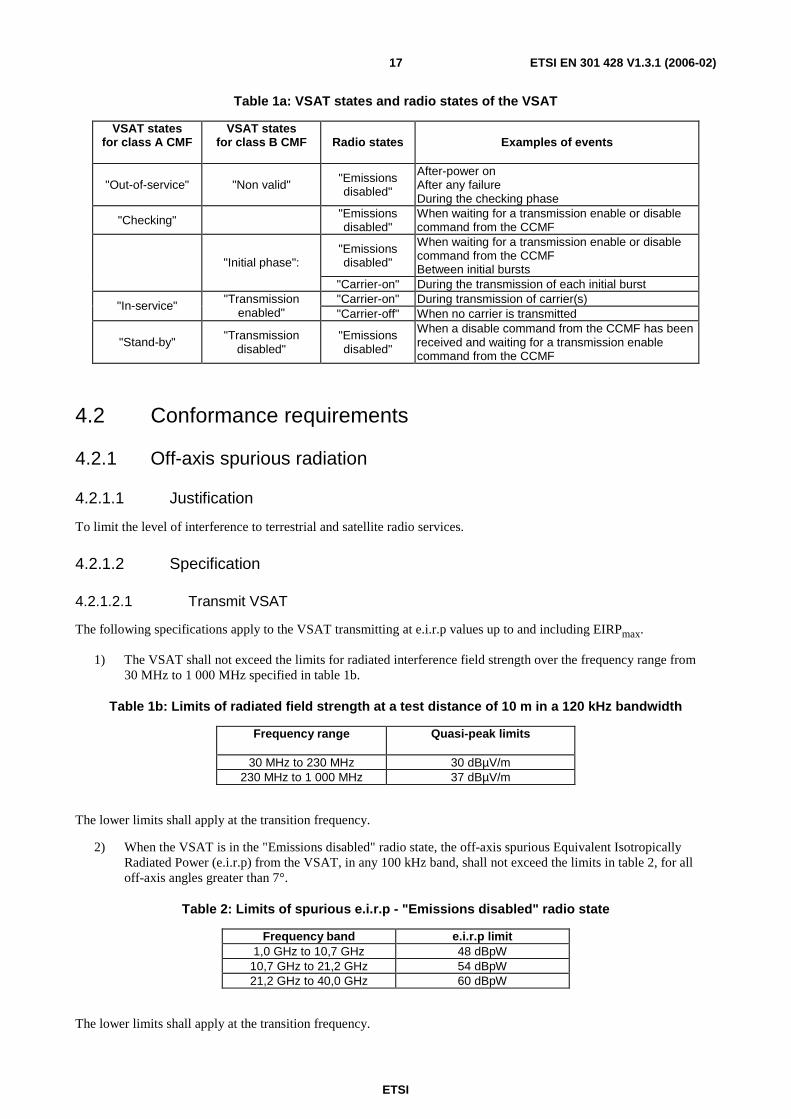
Table 1a gives the only possible combinations of the VSAT states and radio states which shall apply, with some examples of associated events.
When the VSAT transmits several carriers having different frequencies, a VSAT state machine as described above may be associated with each carrier or each set of carriers.
ETSI
ETSI EN 301 428 V1.3.1 (2006-02) 17
Table 1a: VSAT states and radio states of the VSAT
VSAT states for class A CMF
VSAT states for class B CMF
Radio states Examples of events
"Out-of-service" "Non valid" "Emissions disabled"
After-power on After any failure During the checking phase
"Checking" "Emissions disabled"
When waiting for a transmission enable or disable command from the CCMF
"Emissions disabled"
When waiting for a transmission enable or disable command from the CCMF Between initial bursts "Initial phase":
"Carrier-on" During the transmission of each initial burst "Carrier-on" During transmission of carrier(s) "In-service" "Transmission
enabled" "Carrier-off" When no carrier is transmitted
"Stand-by" "Transmission disabled"
"Emissions disabled"
When a disable command from the CCMF has been received and waiting for a transmission enable command from the CCMF
4.2 Conformance requirements
4.2.1 Off-axis spurious radiation
4.2.1.1 Justification
To limit the level of interference to terrestrial and satellite radio services.
4.2.1.2 Specification
4.2.1.2.1 Transmit VSAT
The following specifications apply to the VSAT transmitting at e.i.r.p values up to and including EIRPmax.
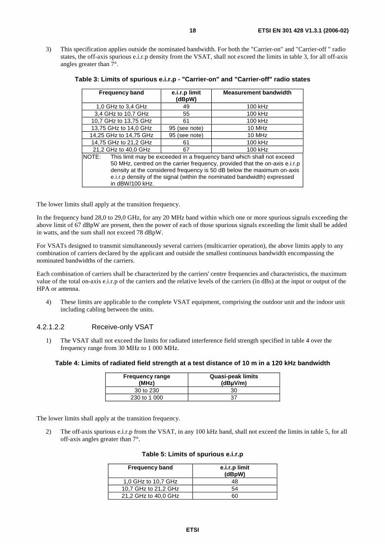
1) The VSAT shall not exceed the limits for radiated interference field strength over the frequency range from 30 MHz to 1 000 MHz specified in table 1b.
Table 1b: Limits of radiated field strength at a test distance of 10 m in a 120 kHz bandwidth
Frequency range
Quasi-peak limits
30 MHz to 230 MHz 30 dBµV/m 230 MHz to 1 000 MHz 37 dBµV/m
The lower limits shall apply at the transition frequency.
2) When the VSAT is in the "Emissions disabled" radio state, the off-axis spurious Equivalent Isotropically Radiated Power (e.i.r.p) from the VSAT, in any 100 kHz band, shall not exceed the limits in table 2, for all off-axis angles greater than 7°.
Table 2: Limits of spurious e.i.r.p - "Emissions disabled" radio state
Frequency band e.i.r.p limit 1,0 GHz to 10,7 GHz 48 dBpW
10,7 GHz to 21,2 GHz 54 dBpW 21,2 GHz to 40,0 GHz 60 dBpW
The lower limits shall apply at the transition frequency.
ETSI
ETSI EN 301 428 V1.3.1 (2006-02) 18
3) This specification applies outside the nominated bandwidth. For both the "Carrier-on" and "Carrier-off " radio states, the off-axis spurious e.i.r.p density from the VSAT, shall not exceed the limits in table 3, for all off-axis angles greater than 7°.
Table 3: Limits of spurious e.i.r.p - "Carrier-on" and "Carrier-off" radio states
Frequency band e.i.r.p limit (dBpW)
Measurement bandwidth
1,0 GHz to 3,4 GHz 49 100 kHz 3,4 GHz to 10,7 GHz 55 100 kHz
10,7 GHz to 13,75 GHz 61 100 kHz 13,75 GHz to 14,0 GHz 95 (see note) 10 MHz
14,25 GHz to 14,75 GHz 95 (see note) 10 MHz 14,75 GHz to 21,2 GHz 61 100 kHz 21,2 GHz to 40,0 GHz 67 100 kHz
NOTE: This limit may be exceeded in a frequency band which shall not exceed 50 MHz, centred on the carrier frequency, provided that the on-axis e.i.r.p density at the considered frequency is 50 dB below the maximum on-axis e.i.r.p density of the signal (within the nominated bandwidth) expressed in dBW/100 kHz.
The lower limits shall apply at the transition frequency.
In the frequency band 28,0 to 29,0 GHz, for any 20 MHz band within which one or more spurious signals exceeding the above limit of 67 dBpW are present, then the power of each of those spurious signals exceeding the limit shall be added in watts, and the sum shall not exceed 78 dBpW.
For VSATs designed to transmit simultaneously several carriers (multicarrier operation), the above limits apply to any combination of carriers declared by the applicant and outside the smallest continuous bandwidth encompassing the nominated bandwidths of the carriers.
Each combination of carriers shall be characterized by the carriers' centre frequencies and characteristics, the maximum value of the total on-axis e.i.r.p of the carriers and the relative levels of the carriers (in dBs) at the input or output of the HPA or antenna.
4) These limits are applicable to the complete VSAT equipment, comprising the outdoor unit and the indoor unit including cabling between the units.
4.2.1.2.2 Receive-only VSAT
1) The VSAT shall not exceed the limits for radiated interference field strength specified in table 4 over the frequency range from 30 MHz to 1 000 MHz.
Table 4: Limits of radiated field strength at a test distance of 10 m in a 120 kHz bandwidth
Frequency range (MHz)
Quasi-peak limits (dBµV/m)
30 to 230 30 230 to 1 000 37
The lower limits shall apply at the transition frequency.
2) The off-axis spurious e.i.r.p from the VSAT, in any 100 kHz band, shall not exceed the limits in table 5, for all off-axis angles greater than 7°.
Table 5: Limits of spurious e.i.r.p
Frequency band e.i.r.p limit (dBpW)
1,0 GHz to 10,7 GHz 48 10,7 GHz to 21,2 GHz 54 21,2 GHz to 40,0 GHz 60
ETSI
ETSI EN 301 428 V1.3.1 (2006-02) 19
The lower limits shall apply at the transition frequency.
3) These limits are applicable to the complete Receive-only VSAT equipment, comprising the outdoor unit and the indoor unit including the cabling between the units.
4.2.1.3 Conformance tests
Conformance tests shall be carried out in accordance with clause 6.2.
4.2.2 On-axis spurious radiation for transmit VSAT
4.2.2.1 Justification
To limit the level of interference to satellite radio services.
4.2.2.2 Specification
4.2.2.2.1 Specification 1: "Carrier-on" radio state
The following specification applies to the VSAT transmitting at e.i.r.p values up to EIRPnom. For EIRPs above
EIRPnom (when uplink power control is implemented) the limits below may be exceeded by the difference in dB
between the current e.i.r.p and EIRPnom.
In the 14,0 GHz to 14,5 GHz band the e.i.r.p spectral density of the spurious radiation and outside the nominated bandwidth shall not exceed 4 - 10 log N dBW in any 100 kHz band.
The above limit may be exceeded in a bandwidth of 5 times the occupied bandwidth centred on the carrier centre frequency, in which case the e.i.r.p spectral density of the spurious radiation outside the nominated bandwidth, shall not exceed 18 - 10 log N dBW in any 100 kHz band.
N is the maximum number of VSAT which are expected to transmit simultaneously in the same carrier frequency band. This number shall not be exceeded for more than 0,01 % of the time. The value of N and the operational conditions of the system shall be declared by the applicant.
NOTE 1: The on-axis spurious radiations, outside the 14,0 GHz to 14,5 GHz band, are indirectly limited by the off-axis limits given in clause 4.2.1.2.1. Consequently no specification is needed.
NOTE 2: Intermodulation limits inside the band 14,0 GHz to 14,5 GHz are to be determined by system design and are subject to satellite operator specifications.
For VSAT designed to transmit simultaneously several different carriers (multicarrier operation), the above limits only apply to each individual carrier when transmitted alone.
4.2.2.2.2 Specification 2: "Carrier-off" and "Emissions disabled" radio states
The following specification applies for a transmit VSAT in the "Carrier-off" and "Emissions disabled" radio states.
In the 14,0 GHz to 14,5 GHz band the e.i.r.p spectral density of the spurious radiation outside the nominated bandwidth shall not exceed -21 dBW in any 100 kHz band.
4.2.2.3 Conformance tests
Conformance tests shall be carried out in accordance with clause 6.3.
4.2.3 Off-axis e.i.r.p emission density within the band
Off-axis e.i.r.p emission density (co-polar and cross-polar) within the band 14,0 GHz to 14,5 GHz.
ETSI
ETSI EN 301 428 V1.3.1 (2006-02) 20
4.2.3.1 Justification
Protection of other satellite (uplink) systems.
4.2.3.2 Specification
The following specifications apply to the VSAT transmitting at e.i.r.p values up to EIRPmax.
The maximum e.i.r.p in any 40 kHz band within the nominated bandwidth of the co-polarized component in any direction φ degrees from the antenna main beam axis shall not exceed the following limits:
33 - 25 log φ - 10 log N dBW for 2,5° ≤ φ ≤ 7,0°;
+12 - 10 log N dBW for 7,0° < φ ≤ 9,2°;
36 - 25 log φ - 10 log N dBW for 9,2° < φ ≤ 48°;
- 6 - 10 log N dBW for φ > 48°.
Where φ is the angle, in degrees, between the main beam axis and the direction considered, and N is the maximum number of VSAT which may transmit simultaneously in the same 40 kHz band. This number shall be declared by the applicant.
NOTE 1: N equals 1 in a TDMA system.
For φ > 70° the values given above may be increased to 4 - 10 log N dBW over the range of angles for which the particular feed system may give rise to relatively high levels of spillover.
Any antenna off-axis direction may be defined by a pair of values (α,φ) where φ is the off-axis angle of that direction with the antenna main beam axis and α is the angle of the plane defined by that direction and the antenna main beam axis with an arbitrary reference plane containing the antenna main beam axis. The range of values of φ and α is from 0° to 180° for φ, and from -180° to +180° for α.
The above limits apply to any off-axis direction (α,φ) within ±3° of the visible part of the GSO and may be exceeded up to 3 dB in any other direction. The above limits may also be exceeded by up to 3 dB for φ greater than 20° and within ±3° of the visible part of the GSO provided that the total angular range over which this occurs does not exceed 20° when measured along both sides of the geostationary orbit. The concerned off-axis direction (α,φ) within ±3° of the visible part of the GSO under all operational conditions declared by the applicant shall be any direction within the (α,φ) domain unless it can be demonstrated by documentary evidence that only a limited subset of the (α,φ) domain is concerned. Outside this subset the +3 dB relaxation applies.
When documentary evidence is provided to demonstrate that only a limited subset of the (α,φ) domain is concerned, the determination of the (α,φ) subset shall take into account the operational conditions for which the VSAT is designed, as declared by the applicant or indicated within the user documentation. These conditions shall include:
• the range of latitudes of the VSAT;
• the minimum elevation pointing angle;
• the type of antenna mount (e.g. with azimuth and elevation axes or equatorial);
• the range of adjustment for the major axis of the antenna for antennas with asymmetric main beam;
• the method of alignment of the antenna major axis with the GSO for antennas with asymmetric main beam;
• the maximum static and dynamic alignment errors of the antenna mount axes;
• the maximum static and dynamic alignment errors of the antenna major axis with respect to the GSO arc for antennas with asymmetric main beam;
• the range of directions of the electric field radiated by the satellite(s) with respect to the Earth's axis for which the equipment is designed, when the electric field is used for the antenna alignment.
ETSI
ETSI EN 301 428 V1.3.1 (2006-02) 21
The alignment errors shall not exceed the declared maximum values when applying the alignment method declared by the applicant or indicated within the user documentation.
NOTE 2: The TR 102 375 gives guidance for the determination of the concerned subset within the (α,φ) domain.
In addition the maximum e.i.r.p in any 40 kHz band within the nominated bandwidth of the cross-polarized component in any direction φ degrees from the antenna main beam axis shall not exceed the following limits:
23 - 25 log φ - 10 log N dBW for 2,5° ≤ φ ≤ 7,0°;
+2 - 10 log N dBW for 7,0° < φ ≤ 9,2°.
Where φ and N are as defined above. For non-continuous transmission, the above limits may not apply for a specific portion of each burst as declared by the applicant. This excluded portion shall not exceed 50 µsec or 10 % of the burst, whichever is the smaller.
The excluded portion shall have characteristics similar to the remaining part of the burst:
• same symbol rate and modulation; and
• same or lower maximum amplitude.
In the case of VSATs employing uplink power density control, the above limits, for co-polar and cross-polar components, shall apply under clear-sky conditions and these limits include all additional margins above the minimum clear-sky level necessary for the implementations of uplink power density control. For VSATs implementing uplink power density control, the above limits may be exceeded by up to A dB during fade conditions, where A is the attenuation of the transmit signal relative to clear sky conditions.
The uplink power density control shall be subject to following additional requirement:
• The value of A shall not exceed 10 dB.
In the case of VSATs employing transmission parameter modification (e.g. FEC, modulation, symbol rate) of the transmitted signal as part of uplink power density control, the above limits shall apply to all combinations of occupied bandwidth and transmission parameters as declared by the applicant.
4.2.3.3 Conformance tests
Conformance tests shall be carried out in accordance with clause 6.4.1 with the results being computed in accordance with clause 6.4.2.
4.2.4 Carrier suppression
4.2.4.1 Justification
To allow for the satisfactory suppression of transmissions of a VSAT in the "Emissions disabled" radio state (e.g. when requested by the CCMF or a fault condition is detected).
4.2.4.2 Specification
In the "Emissions disabled" radio state the on-axis e.i.r.p density shall not exceed 4 dBW in any 4 kHz band within the nominated bandwidth.
4.2.4.3 Conformance tests
Conformance tests shall be carried out in accordance with clause 6.5.
ETSI
ETSI EN 301 428 V1.3.1 (2006-02) 22
4.2.5 Mechanical (antenna pointing) for transmit VSAT
4.2.5.1 Justification
Protection of signals to and from both the same and adjacent satellites.
4.2.5.2 Specification
a) Pointing stability:
Under the condition of 100 km/h maximum wind speed, with gusts of 130 km/h lasting 3 seconds, the installation shall not show any sign of permanent distortion and shall not need repointing after the application of the wind load.
b) Pointing accuracy capability:
Specification 1: Main beam pointing accuracy
The antenna mount shall allow the position of the antenna transmit main beam axis to be maintained with an accuracy better than the off-axis angle measured when the main beam gain has decreased by 1 dB at any frequency in the equipment operating band, over the full range of azimuth and elevation movement available to the antenna.
Specification 2: Non-symmetrical main beam orientation
For antennas with asymmetric main beam, the antenna shall be capable of having the plane defined by the antenna main beam axis and its major axis aligned with the tangent to the geostationary orbit in accordance with the method declared by the applicant.
c) Polarization angle alignment capability:
When linear polarization is used, the polarization angle shall be continuously adjustable in a range of at least 180°.
It shall be possible to fix the transmit antenna polarization angle with an accuracy of at least 1°.
4.2.5.3 Conformance tests
Conformance tests shall be carried out in accordance with clause 6.6.
4.2.6 Class A Control and Monitoring Functions
4.2.6.1 Control and Monitoring Functions (CMF)
4.2.6.1.1 General
The following minimum set of control and monitoring functions shall be implemented in VSAT in order to minimize the probability that they may originate transmissions that may interfere with other systems.
4.2.6.1.2 CMF state transition diagram
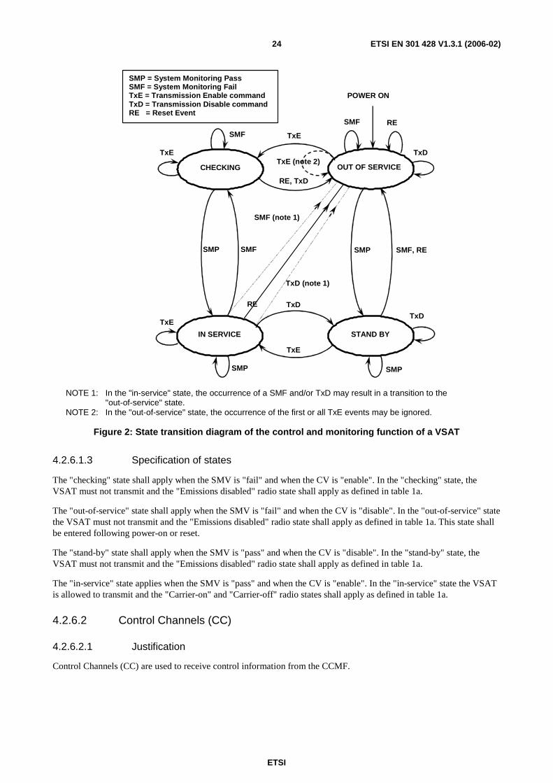
A VSAT shall implement two sets of control and monitoring functions:
a) Monitoring functions: these functions encompass all the checks and verifications that the VSAT shall perform in order to identify any anomalous situation which may cause impairments to other systems.
The overall result of these checks and verifications are contained in a functional variable named Self Monitoring Variable (SMV). The states of this variable are "Pass" and "Fail".
The state of the SMV may change as a result of events. These are:
- System Monitoring Pass event (SMP);
- System Monitoring Fail event (SMF).
ETSI
ETSI EN 301 428 V1.3.1 (2006-02) 23
The circumstances under which these events may take place are specified in clause 4.2.6.3 of the present document.
b) Control functions: these functions are associated with the ability of the CCMF to inhibit and to permit transmissions from an individual VSAT.
These functions are reflected in the state of a functional variable, resident at each VSAT, named Control Variable (CV). The states of this variable are "enable" and "disable".
The CV may change as a result of events. These are:
- Transmission Disable command (TxD);
- Transmission Enable command (TxE).
The circumstances associated to the reception of the messages resulting in these events are specified in clause 4.2.6.4 of the present document.
VSAT that allow local operator intervention may include a terminal reset function which when actuated results in a Reset Event (RE).
Clause 4.2.6.5 specifies the functions associated with the occurrence of the "power-on" and REs.
The combination of the SMV and CV results in the definition of 4 possible states in which a VSAT may be from the control and monitoring point-of-view.
The states of the VSAT are:
- out-of-service;
- checking;
- stand-by;
- in-service.
Figure 2 shows the state transition diagram associated with these 4 states. The operational behaviour of the VSAT (with respect to control and monitoring), in each of these states, is specified in clause 4.2.6.1.3.
When the VSAT transmits several carriers having different frequencies, a VSAT state machine as described above may be associated with each carrier or each set of carriers. The events then apply to the subsystem associated with the specific carrier or the specific set of carriers, rather than the whole VSAT.
ETSI
ETSI EN 301 428 V1.3.1 (2006-02) 24
CHECKING OUT OF SERVICE
STAND BY IN SERVICE
RE, TxD
TxE
TxD
TxE
SMP SMF SMF, RE SMP
RE
SMF (note 1)
TxD (note 1)
TxD
TxD
TxE
TxE
SMF
SMF
TxE (note 2)
POWER ON
SMP SMP
RE
SMP = System Monitoring Pass SMF = System Monitoring Fail TxE = Transmission Enable command TxD = Transmission Disable command RE = Reset Event
NOTE 1: In the "in-service" state, the occurrence of a SMF and/or TxD may result in a transition to the "out-of-service" state.
NOTE 2: In the "out-of-service" state, the occurrence of the first or all TxE events may be ignored.
Figure 2: State transition diagram of the control and monitoring function of a VSAT
4.2.6.1.3 Specification of states
The "checking" state shall apply when the SMV is "fail" and when the CV is "enable". In the "checking" state, the VSAT must not transmit and the "Emissions disabled" radio state shall apply as defined in table 1a.
The "out-of-service" state shall apply when the SMV is "fail" and when the CV is "disable". In the "out-of-service" state the VSAT must not transmit and the "Emissions disabled" radio state shall apply as defined in table 1a. This state shall be entered following power-on or reset.
The "stand-by" state shall apply when the SMV is "pass" and when the CV is "disable". In the "stand-by" state, the VSAT must not transmit and the "Emissions disabled" radio state shall apply as defined in table 1a.
The "in-service" state applies when the SMV is "pass" and when the CV is "enable". In the "in-service" state the VSAT is allowed to transmit and the "Carrier-on" and "Carrier-off" radio states shall apply as defined in table 1a.
4.2.6.2 Control Channels (CC)
4.2.6.2.1 Justification
Control Channels (CC) are used to receive control information from the CCMF.
ETSI
ETSI EN 301 428 V1.3.1 (2006-02) 25
4.2.6.2.2 Specification
a) Specification 1:
The VSAT shall have at least one CC with the CCMF. The CC shall be either internal or external.
The type of CC (internal or external) shall be declared by the applicant.
NOTE 1: The availability of the external CC and the number of external CC are not within the scope of the present document.
NOTE 2: Some satellite operators may require that internal CC are available.
b) Specification 2 for internal CC:
The VSAT shall monitor the operation of its CC receive subsystem, i.e. its ability to lock to the received carrier frequency, demodulate, decode and receive messages from the CCMF.
Failure of the CC receive subsystem for a period of time longer than 30 seconds shall result in a SMF event. The corresponding change of state shall occur not later than 33 seconds after the beginning of the failure.
c) Specification 3 for internal CC:
The VSAT shall hold, in non-volatile memory, two unique identification codes:
- the identification code of the control channel or channels which it is authorized to receive; and
- the identification code of the VSAT when the CC is received by more than one VSAT.
Failure to receive and validate an authorized control identification code for a period of time not exceeding 60 seconds shall result in a SMF event. The corresponding change of state shall occur not later than 63 seconds after the beginning of the failure.
The VSAT shall be capable of receiving, via any authorized control channel, messages addressed to the VSAT containing TxD and TxE.
d) Specification 4 for external CC:
The VSAT shall be able either to be permanently connected to the CCMF or to be connected to the CCMF on demand, in order to receive messages from the CCMF containing TxD and TxE.
4.2.6.2.3 Conformance tests
Conformance tests shall be carried out in accordance with clause 6.7.3.
4.2.6.3 Self monitoring functions
4.2.6.3.1 General
In order to ensure that all the subsystems of the VSAT are operating correctly during transmission, the following self monitoring functions shall be implemented in the VSAT:
- processor monitoring;
- transmit subsystem monitoring;
- VSAT transmission validation.
The successful verification of all conditions shall result in a SMP event.
The failure of any of the conditions shall result in a SMF event.
The monitoring functions shall be performed in all states of the VSAT.

ETSI
ETSI EN 301 428 V1.3.1 (2006-02) 26
4.2.6.3.2 Processor monitoring
4.2.6.3.2.1 Justification
To ensure that the VSAT can suppress transmissions in the event of a processor failure.
4.2.6.3.2.2 Specification
A VSAT shall incorporate a processor monitoring function for each of its processors involved in the manipulation of traffic and in the control and monitoring functions.
The processor monitoring function shall verify the correct operation of the processor hardware and software.
The detection by the processor monitoring function of a processor fault for a period of time not exceeding 30 seconds shall result in an SMF event. The corresponding change of state shall occur not later than 33 seconds after fault occurrence.
4.2.6.3.2.3 Conformance tests
Conformance tests shall be carried out in accordance with clause 6.7.4.
4.2.6.3.3 Transmit subsystem monitoring
4.2.6.3.3.1 Justification
To ensure that the VSAT can suppress the transmissions in the event of a transmit subsystem error.
4.2.6.3.3.2 Specification
A VSAT shall monitor the operation of its transmit frequency generation subsystem.
Failure of the transmit frequency generation subsystem for a period of time not exceeding 5 seconds shall result in a SMF event. The corresponding change of state shall occur no later than 8 seconds after the beginning of the failure.
4.2.6.3.3.3 Conformance tests
Conformance tests shall be carried out in accordance with clause 6.7.5.
4.2.6.3.4 VSAT transmission validation
4.2.6.3.4.1 General
For a VSAT using internal CC two alternative methods exist to confirm that the VSAT transmissions are being correctly received. These are:
- transmission validation by the CCMF in accordance with clause 4.2.6.3.4.2;
- transmission validation by receiving station(s) in accordance with clause 4.2.6.3.4.3.
For those VSAT using internal CC at least one of these methods shall be implemented.
For a VSAT using external CC the specification in clause 4.2.6.3.4.4 applies.
4.2.6.3.4.2 VSAT transmission validation by the CCMF
4.2.6.3.4.2.1 Justification
To verify the ability of a transmitting VSAT to send status messages on request received from the CCMF, in order to have its correct operation validated.

ETSI
ETSI EN 301 428 V1.3.1 (2006-02) 27
4.2.6.3.4.2.2 Specification
When the VSAT is in the "in-service" state, and when it receives a "poll-for-status message" from the CCMF via a CC the VSAT shall transmit a "status message". The status message may be transmitted by the VSAT periodically thereafter without further stimuli from the CCMF.
The status message shall be transmitted via an internal RC.
NOTE: The status message is used by the CCMF to verify the correct operation of the VSAT.
4.2.6.3.4.2.3 Conformance tests
Conformance tests shall be carried out in accordance with clause 6.7.6.1.
4.2.6.3.4.3 VSAT transmission validation by receiving station(s)
4.2.6.3.4.3.1 Justification
To ensure that the VSAT transmits correctly, by informing the VSAT that its transmissions are being correctly received at receiving station(s).
For every 10 minutes during which the VSAT transmits at least once, the VSAT should receive at least one "transmission validation message" indicating that its transmissions are being received at the receiving station(s).
4.2.6.3.4.3.2 Specification
If no "transmission validation message" has been received by the VSAT for more than 10 minutes after any transmission, it shall result in a SMF event and the corresponding change of state shall occur not later than 11 minutes from the last "transmission validation message".
4.2.6.3.4.3.3 Conformance tests
Conformance tests shall be carried out in accordance with clause 6.7.6.2.
4.2.6.3.4.4 Transmission validation for VSAT using external CC
4.2.6.3.4.4.1 Justification
To ensure that the transmitting VSAT remains controllable and transmits correctly, by requesting the VSAT to send to the CCMF one or multiple status messages.
4.2.6.3.4.4.2 Specification
When the VSAT is in the "in-service" state, and when it receives a "poll-for-status message" via the CC the VSAT shall respond with a "status message".
The "status message" shall be either:
- transmitted via an external RC and shall contain the values of the assigned e.i.r.p and carrier frequencies of the VSAT; or
- transmitted via an internal RC. In this case, the "status message" is used by the CCMF to verify the correct transmission of the VSAT.
4.2.6.3.4.4.3 Conformance tests
Conformance tests shall be carried out in accordance with clause 6.7.6.3.

ETSI
ETSI EN 301 428 V1.3.1 (2006-02) 28
4.2.6.4 Reception of commands from the CCMF
4.2.6.4.1 General
This clause specifies the conditions the VSAT shall satisfy to consider that it is authorized to transmit.
4.2.6.4.2 Disable message
4.2.6.4.2.1 Justification
To verify the ability of a transmitting VSAT to suppress all its transmissions when it receives a TxD message from the CCMF.
4.2.6.4.2.2 Specification
Reception of a TxD message from the CCMF shall result in a TxD event and the corresponding change of state shall occur within 3 seconds of that event.
4.2.6.4.2.3 Conformance tests
Conformance tests shall be carried out in accordance with clause 6.7.7.
4.2.6.4.3 Enable Message
4.2.6.4.3.1 Justification
To verify the ability of a VSAT to transmit when it has received a TxE message from the CCMF.
4.2.6.4.3.2 Specification
Reception of TxE message from the CCMF shall result in a TxE event.
4.2.6.4.3.3 Conformance tests
Conformance tests shall be carried out in accordance with clause 6.7.7.
4.2.6.5 Power-on/Reset
4.2.6.5.1 Justification
To demonstrate that the VSAT achieves a controlled non-transmitting state following the powering-on of the unit, or the occurrence of a reset made by a local operator when this function is implemented.
4.2.6.5.2 Specification
At "power-on" the VSAT shall immediately enter the "out-of-service" state.
Following the application of a reset to the VSAT, a RE shall be considered to have taken place, causing the unit to enter the "out-of-service" state within 3 seconds.
NOTE: To leave the "out-of-service" state or the "stand by" state, the VSAT needs to receive a TxE message from the CCMF. This TxE message could be either:
- requested by the VSAT via an external CC not carried by the same VSAT network; or
- sent by the CCMF regularly via an internal CC; or
- via an external CC within the same VSAT network.
The manner of reception of this TxE remains a design matter.
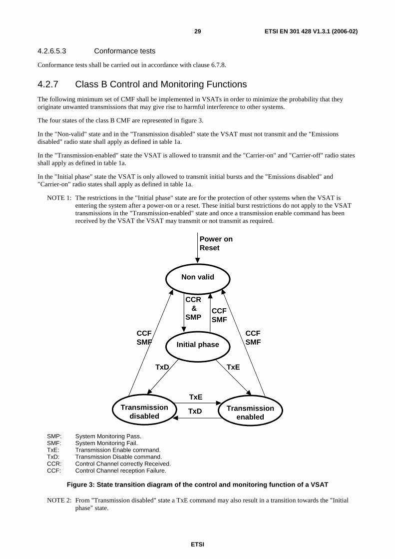
ETSI
ETSI EN 301 428 V1.3.1 (2006-02) 29
4.2.6.5.3 Conformance tests
Conformance tests shall be carried out in accordance with clause 6.7.8.
4.2.7 Class B Control and Monitoring Functions
The following minimum set of CMF shall be implemented in VSATs in order to minimize the probability that they originate unwanted transmissions that may give rise to harmful interference to other systems.
The four states of the class B CMF are represented in figure 3.
In the "Non-valid" state and in the "Transmission disabled" state the VSAT must not transmit and the "Emissions disabled" radio state shall apply as defined in table 1a.
In the "Transmission-enabled" state the VSAT is allowed to transmit and the "Carrier-on" and "Carrier-off" radio states shall apply as defined in table 1a.
In the "Initial phase" state the VSAT is only allowed to transmit initial bursts and the "Emissions disabled" and "Carrier-on" radio states shall apply as defined in table 1a.
NOTE 1: The restrictions in the "Initial phase" state are for the protection of other systems when the VSAT is entering the system after a power-on or a reset. These initial burst restrictions do not apply to the VSAT transmissions in the "Transmission-enabled" state and once a transmission enable command has been received by the VSAT the VSAT may transmit or not transmit as required.
TxE
Transmissiondisabled
Transmissionenabled
Non valid
Initial phase
TxD
TxE
CCR&
SMP
TxD
CCFSMF
CCFSMF
CCFSMF
Power onReset
SMP: System Monitoring Pass. SMF: System Monitoring Fail. TxE: Transmission Enable command. TxD: Transmission Disable command. CCR: Control Channel correctly Received. CCF: Control Channel reception Failure.
Figure 3: State transition diagram of the control and monitoring function of a VSAT
NOTE 2: From "Transmission disabled" state a TxE command may also result in a transition towards the "Initial phase" state.
ETSI
ETSI EN 301 428 V1.3.1 (2006-02) 30
When the VSAT transmits several carriers having different frequencies, a VSAT state machine as described above may be associated with each carrier or each set of carriers. The events then apply to the subsystem associated with the specific carrier or the specific set of carriers, rather than the whole VSAT.
4.2.7.1 Processor monitoring
4.2.7.1.1 Justification
To ensure that the VSAT can suppress transmissions in the event of a processor sub-system failure.
4.2.7.1.2 Specification
The VSAT shall incorporate a processor monitoring function for each of its processors involved in the manipulation of traffic and in Control and Monitoring Functions (CMF).
The processor monitoring function shall detect failures of the processor hardware and software.
No later than 10 seconds after any fault condition occurs, the VSAT shall enter the "Non valid" state until the processor monitoring function has determined that all fault conditions have been cleared.
4.2.7.1.3 Conformance tests
Conformance tests shall be carried out in accordance with clause 6.8.2.
4.2.7.2 Transmit subsystem monitoring
4.2.7.2.1 Justification
To ensure the inhibition of transmissions that are potentially harmful to other systems in the event of incorrect operation of the transmit frequency generation sub-system.
4.2.7.2.2 Specification
The VSAT shall monitor the operation of its transmit frequency generation sub-system and shall be able to detect:
a) loss of frequency lock (if applicable);
b) absence of Local Oscillator (LO) output signal.
No later than 1 second after any of these fault conditions of the transmit frequency generation sub-system occurs, the VSAT shall enter the "Non-valid" state until the transmit sub-system monitoring function has determined that all fault conditions have been cleared.
4.2.7.2.3 Conformance tests
Conformance tests shall be carried out in accordance with clause 6.8.3.
4.2.7.3 Power-on/Reset
4.2.7.3.1 Justification
To demonstrate that the VSAT achieves a controlled non-transmitting state following the powering of the unit, or the occurrence of a reset made by a local operator when this function is implemented.
4.2.7.3.2 Specification
Following a manual reset, when this function is implemented, the VSAT shall enter the "Non-valid" state.
During and following "power-on" the VSAT shall remain in the "Non-valid" state.
ETSI
ETSI EN 301 428 V1.3.1 (2006-02) 31
4.2.7.3.3 Conformance tests
Conformance tests shall be carried out in accordance with clause 6.8.4.
4.2.7.4 Control Channel (CC) reception
4.2.7.4.1 Justification
To ensure that the VSAT cannot transmit unless it correctly receives the CC messages from the CCMF.
4.2.7.4.2 Specification
a) The VSAT shall enter the "Non-valid" state immediately after a period not exceeding 10 seconds without correct reception of the CC from the CCMF.
b) The VSAT shall remain in the "Non-valid" state as long as the CC messages from the CCMF are not received.
c) From the "Non-valid" state the VSAT may enter the "Initial phase" state if the following conditions are met:
- the CC messages from the CCMF are correctly received; and
- no fault conditions are present.
4.2.7.4.3 Conformance tests
Conformance tests shall be carried out in accordance with clause 6.8.5.
4.2.7.5 Network control commands
4.2.7.5.1 Justification
These requirements ensure that the VSAT is capable of:
a) retaining a unique identification in the network;
b) receiving commands from the CCMF through its CC(s) and executing those commands.
4.2.7.5.2 Specification
The VSAT shall hold, in non-volatile memory, its unique identification code in the network.
The VSAT shall be capable of receiving through its CCs dedicated messages (addressed to the VSAT) from the CCMF, and which contain:
- transmission enable commands (TxE);
- transmission disable commands (TxD).
When in the "Initial phase" or "Transmission enabled" states, once a transmission disable command is received, within 10 seconds the VSAT shall enter into, and shall remain in, the "Transmission disabled" state until the transmission disable command is superseded by a subsequent transmission enable command.
When in the "Initial phase" or "Transmission disabled" states, once a transmission enable command is received, the VSAT may enter into the "Transmission enabled" state.
4.2.7.5.3 Conformance test
Conformance tests shall be carried out in accordance with clause 6.8.6.
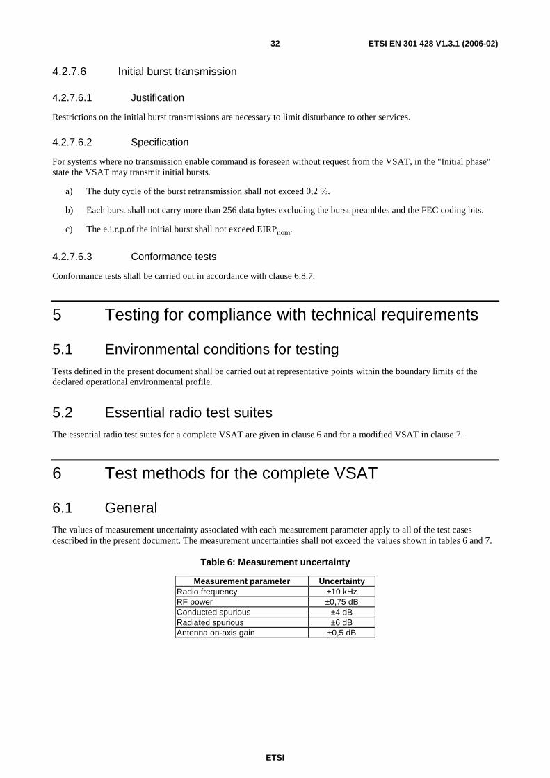
ETSI
ETSI EN 301 428 V1.3.1 (2006-02) 32
4.2.7.6 Initial burst transmission
4.2.7.6.1 Justification
Restrictions on the initial burst transmissions are necessary to limit disturbance to other services.
4.2.7.6.2 Specification
For systems where no transmission enable command is foreseen without request from the VSAT, in the "Initial phase" state the VSAT may transmit initial bursts.
a) The duty cycle of the burst retransmission shall not exceed 0,2 %.
b) Each burst shall not carry more than 256 data bytes excluding the burst preambles and the FEC coding bits.
c) The e.i.r.p.of the initial burst shall not exceed EIRPnom.
4.2.7.6.3 Conformance tests
Conformance tests shall be carried out in accordance with clause 6.8.7.
5 Testing for compliance with technical requirements
5.1 Environmental conditions for testing Tests defined in the present document shall be carried out at representative points within the boundary limits of the declared operational environmental profile.
5.2 Essential radio test suites The essential radio test suites for a complete VSAT are given in clause 6 and for a modified VSAT in clause 7.
6 Test methods for the complete VSAT
6.1 General The values of measurement uncertainty associated with each measurement parameter apply to all of the test cases described in the present document. The measurement uncertainties shall not exceed the values shown in tables 6 and 7.
Table 6: Measurement uncertainty
Measurement parameter Uncertainty Radio frequency ±10 kHz RF power ±0,75 dB Conducted spurious ±4 dB Radiated spurious ±6 dB Antenna on-axis gain ±0,5 dB
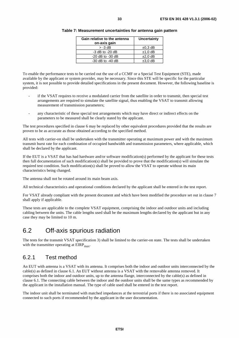
ETSI
ETSI EN 301 428 V1.3.1 (2006-02) 33
Table 7: Measurement uncertainties for antenna gain pattern
Gain relative to the antenna on-axis gain
Uncertainty
> -3 dB ±0,3 dB -3 dB to -20 dB ±1,0 dB
-20 dB to -30 dB ±2,0 dB -30 dB to -40 dB ±3,0 dB
To enable the performance tests to be carried out the use of a CCMF or a Special Test Equipment (STE), made available by the applicant or system provider, may be necessary. Since this STE will be specific for the particular system, it is not possible to provide detailed specifications in the present document. However, the following baseline is provided:
- if the VSAT requires to receive a modulated carrier from the satellite in order to transmit, then special test arrangements are required to simulate the satellite signal, thus enabling the VSAT to transmit allowing measurement of transmission parameters;
- any characteristic of these special test arrangements which may have direct or indirect effects on the parameters to be measured shall be clearly stated by the applicant.
The test procedures specified in clause 6 may be replaced by other equivalent procedures provided that the results are proven to be as accurate as those obtained according to the specified method.
All tests with carrier-on shall be undertaken with the transmitter operating at maximum power and with the maximum transmit burst rate for each combination of occupied bandwidth and transmission parameters, where applicable, which shall be declared by the applicant.
If the EUT is a VSAT that has had hardware and/or software modification(s) performed by the applicant for these tests then full documentation of such modification(s) shall be provided to prove that the modification(s) will simulate the required test condition. Such modification(s) shall be proved to allow the VSAT to operate without its main characteristics being changed.
The antenna shall not be rotated around its main beam axis.
All technical characteristics and operational conditions declared by the applicant shall be entered in the test report.
For VSAT already compliant with the present document and which have been modified the procedure set out in clause 7 shall apply if applicable.
These tests are applicable to the complete VSAT equipment, comprising the indoor and outdoor units and including cabling between the units. The cable lengths used shall be the maximum lengths declared by the applicant but in any case they may be limited to 10 m.
6.2 Off-axis spurious radiation The tests for the transmit VSAT specification 3) shall be limited to the carrier-on state. The tests shall be undertaken with the transmitter operating at EIRPmax.
6.2.1 Test method
An EUT with antenna is a VSAT with its antenna. It comprises both the indoor and outdoor units interconnected by the cable(s) as defined in clause 6.1. An EUT without antenna is a VSAT with the removable antenna removed. It comprises both the indoor and outdoor units, up to the antenna flange, interconnected by the cable(s) as defined in clause 6.1. The connecting cable between the indoor and the outdoor units shall be the same types as recommended by the applicant in the installation manual. The type of cable used shall be entered in the test report.
The indoor unit shall be terminated with matched impedances at the terrestrial ports if there is no associated equipment connected to such ports if recommended by the applicant in the user documentation.
ETSI
ETSI EN 301 428 V1.3.1 (2006-02) 34
For frequencies up to 80 MHz the measuring antenna shall be a balanced dipole with a length equal to the 80 MHz resonant length and shall be matched to the feeder by a suitable transforming device. Measurements with broad band antennas are also possible provided that the test site has been calibrated according to the requirements of CISPR 16-1-5 [2].
For frequencies between 80 MHz and 1 000 MHz the measuring antenna shall be a balanced dipole which shall be resonant in length. Measurements with broad band antennas are also possible provided that the test site has been calibrated according to the requirements of CISPR 16-1-5 [2].
For frequencies above 1 000 MHz the antenna shall be a horn radiator of known gain/frequency characteristics. When used for reception the antenna and any associated amplification system shall have an amplitude/frequency response within ±2 dB of the combined calibration curves across the measurement frequency range considered for the antenna. The antenna is mounted on a support capable of allowing the antenna to be used in either horizontal or vertical polarization and at the specified height.
6.2.1.0 Multi-carrier operation
For VSATs designed to transmit simultaneously several carriers the verification up to 1 000 MHz shall be performed with one or more carriers and the verification above 1 000 MHz shall be repeated for each combination of carriers declared by the applicant.
For each combination of carriers the applicant shall declare the carriers' centre frequencies and characteristics, the maximum value of the total on-axis e.i.r.p of the carriers and the relative levels of the carriers (in dBs) at the input or output of the HPA or antenna.
In the case of combinations of carriers with identical characteristics and when the power at the input of the HPA does not exceed the maximum input power with two carriers (i.e. when the Global Input Back-Off of the HPA is greater than the minimum Global Input Back-Off with two carriers), the verification may be limited to the case with two carriers and with the maximum frequency separation between them.
In any other case, the number of configurations to be verified above may be limited to the cases which can be proven by the applicant, by documentary evidence or demonstration, to generate the maximum e.i.r.p density level of the out-of-band emissions due to inter-modulation products.
6.2.1.1 Up to 1 000 MHz
6.2.1.1.1 Test site
The test shall be performed either in an open area test site, a semi-anechoic chamber or an anechoic chamber. Ambient noise levels shall be at least 6 dB below the applicable unwanted emissions limit.
The open area test site shall be flat, free of overhead wires and nearby reflecting structures, sufficiently large to permit aerial placement at the specified measuring distance and provide adequate separation between aerial, test unit and reflecting structures, according to the specification of CISPR 16-1-5 [2].
For both the open area test site and the semi-anechoic chamber a metal ground plane shall be inserted on the natural ground plane and it shall extend at least 1 m beyond the perimeter of the EUT at one end and at least 1 m beyond the measurement antenna at the other end.
The distance between the EUT and measuring antenna should be 10 m. For measurements at a different distance an inverse proportionality factor of 20 dB per decade shall be used to normalize the measured data to the specified distance for determining compliance. Care should be taken in measurement of large test units at 3 m at frequencies near 30 MHz due to near field effects.
6.2.1.1.2 Measuring receivers
Measuring receivers shall conform to the following characteristics:
- the response to a constant amplitude sine wave signal shall remain within ±1 dB across the frequency range of interest;
- quasi-peak detection shall be used in a -6 dB bandwidth of 120 kHz;

ETSI
ETSI EN 301 428 V1.3.1 (2006-02) 35
- the receiver shall be operated below the 1 dB compression point.
6.2.1.1.3 Procedure
a) The EUT shall be an EUT with antenna or, preferably, without antenna but with the antenna flange terminated by a dummy load.
b) The EUT shall be in the carrier-on state.
c) The EUT shall be rotated through 360° and, except in an anechoic chamber, the measuring antenna height simultaneously varied from 1 m to 4 m above the ground plane.
d) All identified spurious radiations shall be measured and noted in frequency and level.
6.2.1.2 Above 1 000 MHz
The spectrum analyser resolution bandwidth shall be set to the specified measuring bandwidth or as close as possible. If the resolution bandwidth is different from the specified measuring bandwidth, bandwidth correction shall be performed for the noise-like wideband spurious.
For an EUT with antenna the tests shall be performed in two stages for the "Carrier-on" and "Carrier-off" and "Emissions disabled" radio states and the appropriate polarization shall be utilized for both the measuring and substitution antennas:
- Procedure a) Identification of the significant frequencies of spurious radiation.
- Procedure b) Measurement of radiated power levels of identified spurious radiation.
For an EUT without antenna the tests shall be performed in three stages for the "Carrier-on" and "Carrier-off" and "Emissions disabled" radio states:
- Procedure a) Identification of the significant frequencies of spurious radiation.
- Procedure b) Measurement of radiated power levels of identified spurious radiation.
- Procedure c) Measurement of conducted spurious radiation radiated through the antenna flange.
6.2.1.2.1 Identification of the significant frequencies of spurious radiation
6.2.1.2.1.1 Test site
The identification of frequencies emitting from the EUT shall be performed either in an anechoic chamber, an open area test site or a semi-anechoic chamber with the test antenna close to the EUT and at the same height as the volume centre of the EUT.
6.2.1.2.1.2 Procedure
a) The EUT shall be in the carrier-off state (receive-only terminals shall be in the normal operating condition).
b) For an EUT with antenna the main beam of the antenna shall have an angle of elevation of 7°, and, for an EUT without antenna the antenna flange shall be terminated by a dummy load.
c) The receivers shall scan the frequency band whilst the EUT revolves.
d) The EUT shall be rotated though 360° and the frequency of any spurious signals noted for further investigation.
e) For an EUT with antenna the test shall be repeated with the test antenna being in the opposite polarization.
f) For transmit capable equipment the test shall be repeated in the carrier-on state whilst transmitting one modulated carrier at maximum power.

ETSI
ETSI EN 301 428 V1.3.1 (2006-02) 36
6.2.1.2.2 Measurement of radiated power levels of identified spurious radiation
6.2.1.2.2.1 Test site
The measurement of each spurious radiation noted during procedure a) of the test shall be performed on a test site that is free from reflecting objects, i.e. either an open-area test site, a semi-anechoic chamber or an anechoic chamber.
6.2.1.2.2.2 Procedure
EUT
Substitutionantenna
Measuring antenna
Signalgenerator
VSATSpectrumanalyser
Filters
Figure 4: Test arrangement-spurious radiation measurement above 1 000 MHz for an EUT with antenna
EUT
Substitution antenna
Measuring antenna
Signal generator
VSAT Spectrum
analyser Filters Test
load
Figure 5: Test arrangement-spurious radiation measurements above 1 000 MHz for an EUT without antenna
a) The test arrangement shall be as shown in figure 4 or 5.
b) The EUT shall be installed such that the units are separated by about 1 m to 2 m with the indoor unit at a height between 0,5 m and 1,0 m on a turntable. The interconnection cable shall be maintained by non-metallic means at a height between 0,5 m and 1,0 m. For the test arrangement shown in figure 4 the main beam of the antenna shall have an angle of elevation of 7° and be oriented away from the geostationary orbit, or be inhibited by placing RF absorbing panels in that direction. For antennas designed for minimum off-axis gain in the direction of the geostationary orbit plane, the plane containing the larger cut of the main lobe shall be set vertical.
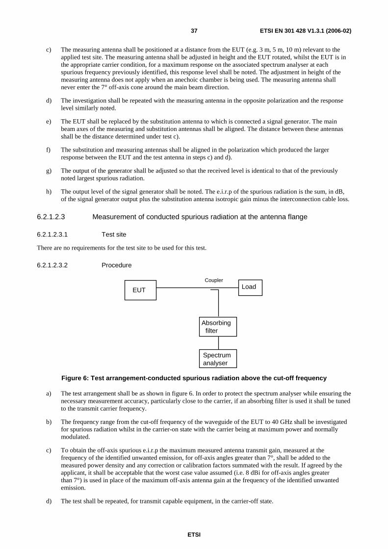
ETSI
ETSI EN 301 428 V1.3.1 (2006-02) 37
c) The measuring antenna shall be positioned at a distance from the EUT (e.g. 3 m, 5 m, 10 m) relevant to the applied test site. The measuring antenna shall be adjusted in height and the EUT rotated, whilst the EUT is in the appropriate carrier condition, for a maximum response on the associated spectrum analyser at each spurious frequency previously identified, this response level shall be noted. The adjustment in height of the measuring antenna does not apply when an anechoic chamber is being used. The measuring antenna shall never enter the 7° off-axis cone around the main beam direction.
d) The investigation shall be repeated with the measuring antenna in the opposite polarization and the response level similarly noted.
e) The EUT shall be replaced by the substitution antenna to which is connected a signal generator. The main beam axes of the measuring and substitution antennas shall be aligned. The distance between these antennas shall be the distance determined under test c).
f) The substitution and measuring antennas shall be aligned in the polarization which produced the larger response between the EUT and the test antenna in steps c) and d).
g) The output of the generator shall be adjusted so that the received level is identical to that of the previously noted largest spurious radiation.
h) The output level of the signal generator shall be noted. The e.i.r.p of the spurious radiation is the sum, in dB, of the signal generator output plus the substitution antenna isotropic gain minus the interconnection cable loss.
6.2.1.2.3 Measurement of conducted spurious radiation at the antenna flange
6.2.1.2.3.1 Test site
There are no requirements for the test site to be used for this test.
6.2.1.2.3.2 Procedure
Spectrum analyser
EUT Load
Absorbing filter
Coupler
Figure 6: Test arrangement-conducted spurious radiation above the cut-off frequency
a) The test arrangement shall be as shown in figure 6. In order to protect the spectrum analyser while ensuring the necessary measurement accuracy, particularly close to the carrier, if an absorbing filter is used it shall be tuned to the transmit carrier frequency.
b) The frequency range from the cut-off frequency of the waveguide of the EUT to 40 GHz shall be investigated for spurious radiation whilst in the carrier-on state with the carrier being at maximum power and normally modulated.
c) To obtain the off-axis spurious e.i.r.p the maximum measured antenna transmit gain, measured at the frequency of the identified unwanted emission, for off-axis angles greater than 7°, shall be added to the measured power density and any correction or calibration factors summated with the result. If agreed by the applicant, it shall be acceptable that the worst case value assumed (i.e. 8 dBi for off-axis angles greater than 7°) is used in place of the maximum off-axis antenna gain at the frequency of the identified unwanted emission.
d) The test shall be repeated, for transmit capable equipment, in the carrier-off state.
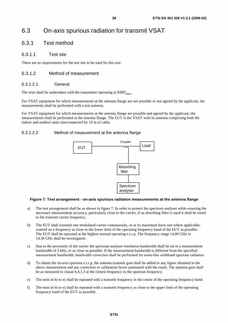
ETSI
ETSI EN 301 428 V1.3.1 (2006-02) 38
6.3 On-axis spurious radiation for transmit VSAT
6.3.1 Test method
6.3.1.1 Test site
There are no requirements for the test site to be used for this test.
6.3.1.2 Method of measurement
6.3.1.2.1 General
The tests shall be undertaken with the transmitter operating at EIRPmax.
For VSAT equipment for which measurements at the antenna flange are not possible or not agreed by the applicant, the measurements shall be performed with a test antenna.
For VSAT equipment for which measurements at the antenna flange are possible and agreed by the applicant, the measurements shall be performed at the antenna flange. The EUT is the VSAT with its antenna comprising both the indoor and outdoor units interconnected by 10 m of cable.
6.3.1.2.2 Method of measurement at the antenna flange
Spectrum analyser
EUT Load
Absorbing filter
Coupler
Figure 7: Test arrangement - on-axis spurious radiation measurements at the antenna flange
a) The test arrangement shall be as shown in figure 7. In order to protect the spectrum analyser while ensuring the necessary measurement accuracy, particularly close to the carrier, if an absorbing filter is used it shall be tuned to the transmit carrier frequency.
b) The EUT shall transmit one modulated carrier continuously, or at its maximum burst rate where applicable, centred on a frequency as close to the lower limit of the operating frequency band of the EUT as possible. The EUT shall be operated at the highest normal operating e.i.r.p. The frequency range 14,00 GHz to 14,50 GHz shall be investigated.
c) Due to the proximity of the carrier the spectrum analyser resolution bandwidth shall be set to a measurement bandwidth of 3 kHz, or as close as possible. If the measurement bandwidth is different from the specified measurement bandwidth, bandwidth correction shall be performed for noise-like wideband spurious radiation.
d) To obtain the on-axis spurious e.i.r.p, the antenna transmit gain shall be added to any figure obtained in the above measurement and any correction or calibration factor summated with the result. The antenna gain shall be as measured in clause 6.4.1.3 at the closest frequency to the spurious frequency.
e) The tests in b) to e) shall be repeated with a transmit frequency in the centre of the operating frequency band.
f) The tests in b) to e) shall be repeated with a transmit frequency as close to the upper limit of the operating frequency band of the EUT as possible.
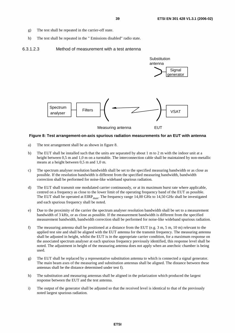
ETSI
ETSI EN 301 428 V1.3.1 (2006-02) 39
g) The test shall be repeated in the carrier-off state.
h) The test shall be repeated in the " Emissions disabled" radio state.
6.3.1.2.3 Method of measurement with a test antenna
EUT
Substitution antenna
Measuring antenna
Signal generator
VSAT Spectrum
analyser Filters
Figure 8: Test arrangement-on-axis spurious radiation measurements for an EUT with antenna
a) The test arrangement shall be as shown in figure 8.
b) The EUT shall be installed such that the units are separated by about 1 m to 2 m with the indoor unit at a height between 0,5 m and 1,0 m on a turntable. The interconnection cable shall be maintained by non-metallic means at a height between 0,5 m and 1,0 m.
c) The spectrum analyser resolution bandwidth shall be set to the specified measuring bandwidth or as close as possible. If the resolution bandwidth is different from the specified measuring bandwidth, bandwidth correction shall be performed for noise-like wideband spurious radiation.
d) The EUT shall transmit one modulated carrier continuously, or at its maximum burst rate where applicable, centred on a frequency as close to the lower limit of the operating frequency band of the EUT as possible. The EUT shall be operated at EIRPmax. The frequency range 14,00 GHz to 14,50 GHz shall be investigated
and each spurious frequency shall be noted.
e) Due to the proximity of the carrier the spectrum analyser resolution bandwidth shall be set to a measurement bandwidth of 3 kHz, or as close as possible. If the measurement bandwidth is different from the specified measurement bandwidth, bandwidth correction shall be performed for noise-like wideband spurious radiation.
f) The measuring antenna shall be positioned at a distance from the EUT (e.g. 3 m, 5 m, 10 m) relevant to the applied test site and shall be aligned with the EUT antenna for the transmit frequency. The measuring antenna shall be adjusted in height, whilst the EUT is in the appropriate carrier condition, for a maximum response on the associated spectrum analyser at each spurious frequency previously identified, this response level shall be noted. The adjustment in height of the measuring antenna does not apply when an anechoic chamber is being used.
g) The EUT shall be replaced by a representative substitution antenna to which is connected a signal generator. The main beam axes of the measuring and substitution antennas shall be aligned. The distance between these antennas shall be the distance determined under test f).
h) The substitution and measuring antennas shall be aligned in the polarization which produced the largest response between the EUT and the test antenna.
i) The output of the generator shall be adjusted so that the received level is identical to that of the previously noted largest spurious radiation.

ETSI
ETSI EN 301 428 V1.3.1 (2006-02) 40
j) The output level of the signal generator shall be noted. The e.i.r.p of the on-axis spurious radiation is the sum, in dB, of the signal generator output plus the substitution antenna isotropic gain minus the interconnection cable loss.
k) The tests in d) to j) shall be repeated with a transmit frequency in the centre of the operating frequency band.
l) The tests in d) to j) shall be repeated with a transmit frequency as close to the upper limit of the operating frequency band of the EUT as possible.
m) The test shall be repeated in the carrier-off state.
n) The test shall be repeated in the " Emissions disabled" radio state.
6.4 Off-axis e.i.r.p emission density within the band Off-axis e.i.r.p emission density (co-polar and cross-polar) within the band 14,0 GHz to 14,5 GHz.
6.4.1 Test method
6.4.1.1 General
The measurement shall be made in the operational configuration(s) (occupied bandwidth, EIRPnom) producing the
highest emission density in the frequency band. The selected configuration(s) shall be recorded in the test report. All of the e.i.r.p emission density measurement shall be performed at EIRPnom.
If the test is to be carried out with an STE, then the STE shall provide all the signals needed by the VSATs under normal operation (e.g a radio beacon if it is expected to be received by the satellite).
For VSATs with uplink power density control capability the compliance of the VSAT with the specification of clause 4.2.3.2 during fading conditions shall be demonstrated by documentary evidence from the applicant.
The e.i.r.p density is determined from the measurements of the antenna copolar and crosspolar gain patterns, and of the power density at the antenna flange. The e.i.r.p density shall be compared to the specified mask.
To ascertain the off-axis e.i.r.p it is necessary to know the transmit power density and antenna transmit radiation pattern. To ascertain the radiation pattern it is necessary to know the antenna transmit gain.
The following three measurement procedures shall, therefore, be performed:
a) transmit output power density (dBW/40 kHz);
b) antenna transmit gain (dBi);
c) antenna transmit radiation patterns (dBi).
6.4.1.2 Transmit output power density
6.4.1.2.1 General
For the purpose of this test the EUT is defined as the indoor unit and that part of the outdoor unit up to the antenna flange.
The EUT output power shall be set to the power corresponding to EIRPnom.
6.4.1.2.2 Test site
There are no requirements for the test site to be used for this test.

ETSI
ETSI EN 301 428 V1.3.1 (2006-02) 41
6.4.1.2.3 Method of measurement
Spectrum analyser
EUT Load Coupler
Figure 9: Test arrangement-transmit output power density measurement
a) The test arrangement shall be as shown in figure 9.
b) The EUT shall transmit one carrier modulated with data or with a pseudo random signal. For burst mode transmission the EUT shall transmit at its maximum burst-rate. The power density supplied to the antenna flange shall be measured in dBW/40 kHz. The coupling factor of the test coupler at the test frequency and the attenuation of any necessary waveguide adapter shall be taken into account.
The spectrum analyser shall be operated under the following conditions:
- frequency span: as required for the complete nominated bandwidth;
- resolution bandwidth: The resolution bandwidth of the spectrum analyser shall be set as close as possible to the specified measuring bandwidth of 40 kHz. If the resolution bandwidth is different from the specified bandwidth then bandwidth correction shall be performed except for spectrum components the width of which are narrower than the measurement bandwidth;
- display/video bandwidth: equal to the resolution bandwidth;
- averaging: yes;
- max hold: no.
If required by the applicant, the test may be performed in max hold mode.
For a VSAT operating in a continuous carrier mode, the measurement time shall be sufficient to ensure that at any frequency the difference between any two measurement results is less than 1 dB.
For a VSAT operating in a non-continuous carrier mode, the average measurement shall be performed over the transmitted burst and the measurements from a series of bursts shall be combined as follows:
- Each measurement may exclude a specific portion of each burst. The excluded portion shall not exceed 50 µs or 10 % of the burst, whichever is the smaller. The excluded portion shall be declared by the applicant.
- The measurements from several bursts shall be averaged to give a final measurement result. The number of bursts that are averaged shall be sufficient to ensure that the difference between any two final measurement results is less than 1 dB.
c) The measurement shall be made in the operational configuration(s) (occupied bandwidth, EIRPnom) producing
the highest emission density in the frequency band. The selected configuration(s) shall be recorded in the test report.
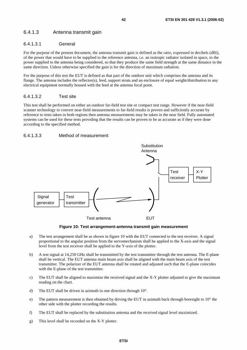
ETSI
ETSI EN 301 428 V1.3.1 (2006-02) 42
6.4.1.3 Antenna transmit gain
6.4.1.3.1 General
For the purpose of the present document, the antenna transmit gain is defined as the ratio, expressed in decibels (dBi), of the power that would have to be supplied to the reference antenna, i.e. an isotropic radiator isolated in space, to the power supplied to the antenna being considered, so that they produce the same field strength at the same distance in the same direction. Unless otherwise specified the gain is for the direction of maximum radiation.
For the purpose of this test the EUT is defined as that part of the outdoor unit which comprises the antenna and its flange. The antenna includes the reflector(s), feed, support struts and an enclosure of equal weight/distribution to any electrical equipment normally housed with the feed at the antenna focal point.
6.4.1.3.2 Test site
This test shall be performed on either an outdoor far-field test site or compact test range. However if the near-field scanner technology to convert near-field measurements to far-field results is proven and sufficiently accurate by reference to tests taken in both regions then antenna measurements may be taken in the near field. Fully automated systems can be used for these tests providing that the results can be proven to be as accurate as if they were done according to the specified method.
6.4.1.3.3 Method of measurement
Signal generator
Test transmitter
Test receiver
X-Y
Plotter
EUT
Substitution Antenna
Test antenna
Figure 10: Test arrangement-antenna transmit gain measurement
a) The test arrangement shall be as shown in figure 10 with the EUT connected to the test receiver. A signal proportional to the angular position from the servomechanism shall be applied to the X-axis and the signal level from the test receiver shall be applied to the Y-axis of the plotter.
b) A test signal at 14,250 GHz shall be transmitted by the test transmitter through the test antenna. The E-plane shall be vertical. The EUT antenna main beam axis shall be aligned with the main beam axis of the test transmitter. The polarizer of the EUT antenna shall be rotated and adjusted such that the E-plane coincides with the E-plane of the test transmitter.
c) The EUT shall be aligned to maximize the received signal and the X-Y plotter adjusted to give the maximum reading on the chart.
d) The EUT shall be driven in azimuth in one direction through 10°.
e) The pattern measurement is then obtained by driving the EUT in azimuth back through boresight to 10° the other side with the plotter recording the results.
f) The EUT shall be replaced by the substitution antenna and the received signal level maximized.
g) This level shall be recorded on the X-Y plotter.
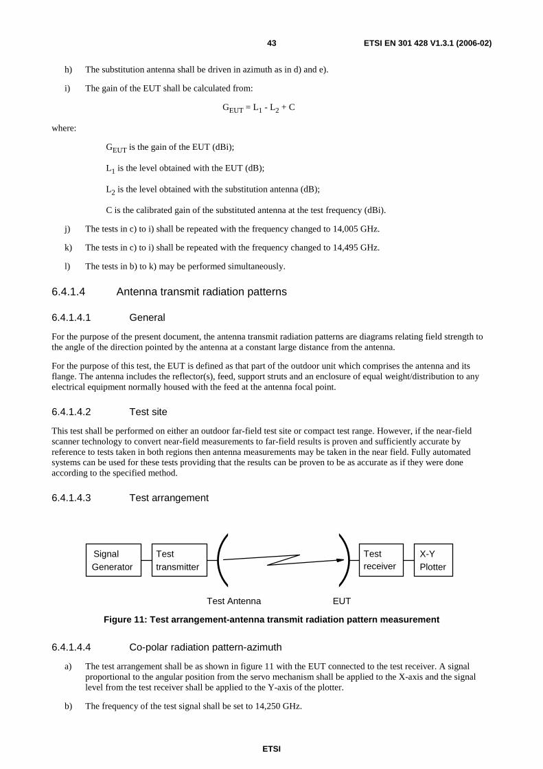
ETSI
ETSI EN 301 428 V1.3.1 (2006-02) 43
h) The substitution antenna shall be driven in azimuth as in d) and e).
i) The gain of the EUT shall be calculated from:
GEUT = L1 - L2 + C
where:
GEUT is the gain of the EUT (dBi);
L1 is the level obtained with the EUT (dB);
L2 is the level obtained with the substitution antenna (dB);
C is the calibrated gain of the substituted antenna at the test frequency (dBi).
j) The tests in c) to i) shall be repeated with the frequency changed to 14,005 GHz.
k) The tests in c) to i) shall be repeated with the frequency changed to 14,495 GHz.
l) The tests in b) to k) may be performed simultaneously.
6.4.1.4 Antenna transmit radiation patterns
6.4.1.4.1 General
For the purpose of the present document, the antenna transmit radiation patterns are diagrams relating field strength to the angle of the direction pointed by the antenna at a constant large distance from the antenna.
For the purpose of this test, the EUT is defined as that part of the outdoor unit which comprises the antenna and its flange. The antenna includes the reflector(s), feed, support struts and an enclosure of equal weight/distribution to any electrical equipment normally housed with the feed at the antenna focal point.
6.4.1.4.2 Test site
This test shall be performed on either an outdoor far-field test site or compact test range. However, if the near-field scanner technology to convert near-field measurements to far-field results is proven and sufficiently accurate by reference to tests taken in both regions then antenna measurements may be taken in the near field. Fully automated systems can be used for these tests providing that the results can be proven to be as accurate as if they were done according to the specified method.
6.4.1.4.3 Test arrangement
Signal Generator
Test transmitter
Test receiver
X-Y
Plotter
EUT Test Antenna
Figure 11: Test arrangement-antenna transmit radiation pattern measurement
6.4.1.4.4 Co-polar radiation pattern-azimuth
a) The test arrangement shall be as shown in figure 11 with the EUT connected to the test receiver. A signal proportional to the angular position from the servo mechanism shall be applied to the X-axis and the signal level from the test receiver shall be applied to the Y-axis of the plotter.
b) The frequency of the test signal shall be set to 14,250 GHz.

ETSI
ETSI EN 301 428 V1.3.1 (2006-02) 44
c) The initial E-plane of the test signal radiated by the test transmitter through its antenna shall be vertical. The EUT antenna main beam axis shall be aligned with the main beam axis of the test transmitter. The polarizer of the EUT antenna shall be rotated and adjusted such that its E-plane coincides with the E-plane of the test transmitter. Precise co-polar peaking of the polarization shall be done by observing the cross-polar minimum (fine adjustment).
d) The EUT shall be aligned to maximize the received signal and the X-Y plotter adjusted to give the maximum reading on the chart.
e) The EUT shall be driven in azimuth to -180°.
f) The transmit pattern measurement is then obtained by driving the EUT in azimuth from -180° to +180° with the plotter recording the results.
g) The tests in d) to f) shall be repeated with the frequency changed to 14,005 GHz.
h) The tests in d) to f) shall be repeated with the frequency changed to 14,495 GHz.
i) The tests in b) to h) may be performed simultaneously.
j) The tests in d) to i) shall be repeated with the E-plane of the test signal being horizontal. The frequency of the test signal shall be set to 14,250 GHz. The polarizer of the EUT antenna shall be rotated and adjusted such that its E-plane coincides with the E-plane of the test transmitter (giving the minimum cross-polar receive signal). Precise co-polar peaking of the polarization shall be done by observing the cross-polar minimum.
6.4.1.4.5 Co-polar radiation pattern-elevation
a) The test arrangement shall be as shown in figure 11 with the EUT connected to the test receiver. A signal proportional to the angular position from the servo mechanism shall be applied to the X-axis and the signal level from the test receiver shall be applied to the Y-axis of the plotter.
b) The frequency of the test signal shall be set to 14,250 GHz.
c) The initial E-plane of the test signal radiated by the test transmitter through its antenna shall be vertical. The EUT antenna main beam axis shall be aligned with the main beam axis of the test transmitter. The polarizer of the EUT antenna shall be rotated and adjusted such that its E-plane coincides with the E-plane of the test transmitter. Precise co-polar peaking of the polarization shall be done by observing the cross-polar minimum (fine adjustment).
d) The EUT shall be aligned to maximize the received signal and the X-Y plotter adjusted to give the maximum reading on the chart.
e) The EUT shall be driven in elevation to -1°.
f) The transmit pattern measurement is then obtained by driving the EUT in elevation from -1° to 70° with the plotter recording the results.
g) The tests in d) to f) shall be repeated with the frequency changed to 14,005 GHz.
h) The tests in d) to f) shall be repeated with the frequency changed to 14,495 GHz.
i) The tests in b) to h) may be performed simultaneously.
j) The tests in d) to i) shall be repeated with the E-plane of the test signal being horizontal. The frequency of the test signal shall be set to 14,250 GHz. The polarizer of the EUT antenna shall be rotated and adjusted such that its E-plane coincides with the E-plane of the test transmitter. The EUT antenna main beam axis shall be aligned with the main beam axis of the test transmitter. Precise co-polar peaking of the polarization plane shall be done by observing the cross-polar minimum (fine adjustment).
ETSI
ETSI EN 301 428 V1.3.1 (2006-02) 45
6.4.1.4.6 Cross-polar radiation pattern-azimuth
a) The test arrangement shall be as shown in figure 11 with the EUT connected to the test receiver. A signal proportional to the angular position from the servo mechanism shall be applied to the X-axis and the signal level from the test receiver shall be applied to the Y-axis of the plotter.
b) The frequency of the test signal shall be set to 14,250 GHz.
c) The initial E-plane of the test signal radiated by the test transmitter through its antenna shall be vertical. The EUT antenna main beam axis shall be aligned with the main beam axis of the test transmitter. The polarizer of the EUT antenna shall be rotated and adjusted such that its E-plane is orthogonal to the E-plane of the test transmitter. Precise fine adjustment of the polarization plane shall be done by observing the cross-polar minimum.
d) In order to adjust the X-Y plotter giving the maximum reading on the chart the boresight co-polar receive signal shall be used.
e) The EUT shall be driven in azimuth to -10°.
f) The transmit pattern measurement is then obtained by driving the EUT in azimuth from -10° to +10° with the plotter recording the results.
g) The tests in d) to f) shall be repeated with the frequency changed to 14,005 GHz.
h) The tests in d) to f) shall be repeated with the frequency changed to 14,495 GHz.
i) The tests in b) to h) may be performed simultaneously.
j) The tests in d) to i) shall be repeated with the E-plane of the test signal being horizontal. The frequency of the test signal shall be set to 14,250 GHz. The EUT antenna main beam axis shall be aligned with the main beam axis of the test transmitter. The polarizer of the EUT antenna shall be rotated and adjusted such that its E-plane is orthogonal with the E-plane of the test transmitter precise fine adjustment of the polarization plane shall be done by observing the cross-polar minimum.
6.4.1.4.7 Cross-polar radiation pattern-elevation
a) The test arrangement shall be as shown in figure 11 with the EUT connected to the test receiver. A signal proportional to the angular position from the servo mechanism shall be applied to the X-axis and the signal level from the test receiver shall be applied to the Y-axis of the plotter.
b) The frequency of the test signal shall be set to 14,250 GHz.
c) The initial E-plane of the test signal radiated by the test transmitter through its antenna shall be vertical. The EUT antenna main beam axis shall be aligned with the main beam axis of the test transmitter. The polarizer of the EUT antenna shall be rotated and adjusted such that its E-plane is orthogonal to the E-plane of the test transmitter. Precise fine adjustment of the polarization plane shall be done by observing the cross-polar minimum.
d) In order to adjust the X-Y plotter giving the maximum reading on the chart the boresight co-polar receive signal shall be used.
e) The EUT shall be driven in elevation to -1°.
f) The transmit pattern measurement is then obtained by driving the EUT in elevation from -1° to +10° with the plotter recording the results.
g) The tests in d) to f) shall be repeated with the frequency changed to 14,005 GHz.
h) The tests in d) to f) shall be repeated with the frequency changed to 14,495 GHz.
i) The tests in b) to h) may be performed simultaneously.
ETSI
ETSI EN 301 428 V1.3.1 (2006-02) 46
j) The tests in d) to i) shall be repeated with the E-plane of the test signal being horizontal. The frequency of the test signal shall be set to 14,250 GHz. The EUT antenna main beam axis shall be aligned with the main beam axis of the test transmitter. The polarizer of the EUT antenna shall be rotated and adjusted such that its E-plane is orthogonal with the E-plane of the test transmitter precise fine adjustment of the polarization plane shall be done by observing the cross-polar minimum.
6.4.2 Computation of results
The results shall be computed by producing a "mask" to the specified limits with the reference level being equal to the sum of the transmitter output power density and the gain of the antenna. This reference shall then be placed on the maximum point of the plots obtained from the transmit radiation pattern measurements, so as to ascertain that the off-axis e.i.r.p density is within the mask, and thus conforming to the specification.
6.5 Carrier suppression
6.5.1 Test method
a) The test arrangement for conducted measurements shall be as shown in figure 7. The test arrangement for radiated measurements shall be as shown in figure 8.
b) The EUT shall transmit one modulated carrier continuously, or at its maximum burst rate where applicable, centred on 14,250 GHz.
c) The resolution bandwidth of the spectrum analyser shall be set to 3 kHz.
d) The " Emissions disabled" radio state shall be obtained by use of the CCMF.
e) For conducted measurements the maximum residual carrier power density within the nominated bandwidth shall be measured and added to the antenna on-axis gain.
f) For radiated measurements the maximum residual e.i.r.p density within the nominated bandwidth shall be measured and recorded.
Instead of the CCMF an STE provided by the applicant may be used to enable the VSAT transmission to be suppressed.
6.6 Antenna pointing for transmit VSAT
6.6.1 Test method
a) Pointing stability:
- As it is considered impracticable to perform the test on pointing stability no test is given.
- The test methodology described in annex B (informative) may be used to show compliance with the specification for pointing stability.
b) Pointing accuracy capability:
1) The EUT shall be inspected to ascertain whether fine adjustment facilities are available for the azimuth axis (coarse adjustment is usually provided by the positioning of the means of attachment).
2) The adjustment facilities shall be examined to determine both the angular movement possible and the means of arresting that movement.
3) The arresting facility shall be examined to determine its permanency.
4) The test shall be repeated for the elevation axis.
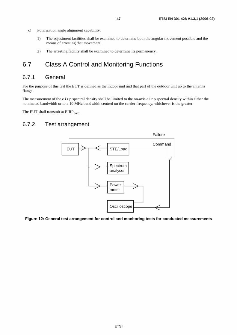
ETSI
ETSI EN 301 428 V1.3.1 (2006-02) 47
c) Polarization angle alignment capability:
1) The adjustment facilities shall be examined to determine both the angular movement possible and the means of arresting that movement.
2) The arresting facility shall be examined to determine its permanency.
6.7 Class A Control and Monitoring Functions
6.7.1 General
For the purpose of this test the EUT is defined as the indoor unit and that part of the outdoor unit up to the antenna flange.
The measurement of the e.i.r.p spectral density shall be limited to the on-axis e.i.r.p spectral density within either the nominated bandwidth or to a 10 MHz bandwidth centred on the carrier frequency, whichever is the greater.
The EUT shall transmit at EIRPnom.
6.7.2 Test arrangement
STE/Load EUT
Spectrum analyser
Power meter
Oscilloscope
Command
Failure
Figure 12: General test arrangement for control and monitoring tests for conducted measurements
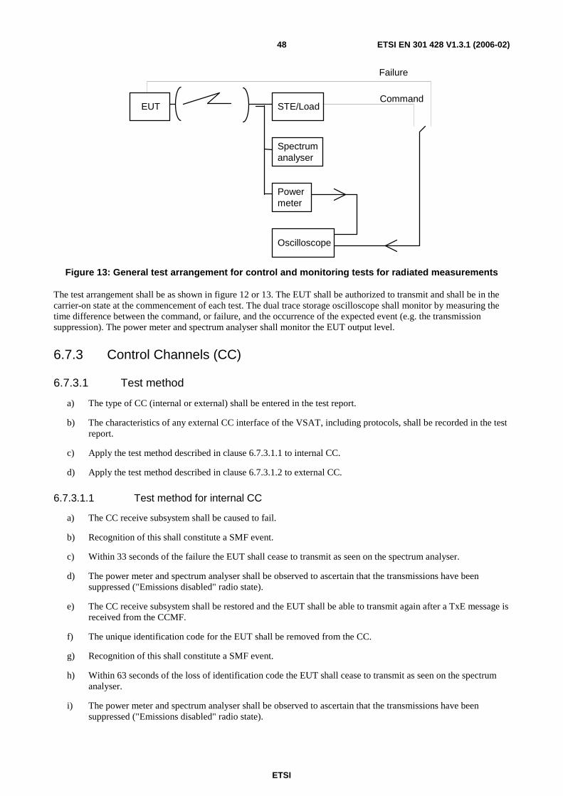
ETSI
ETSI EN 301 428 V1.3.1 (2006-02) 48
STE/Load
Spectrum analyser
Power meter
Oscilloscope
EUT Command
Failure
Figure 13: General test arrangement for control and monitoring tests for radiated measurements
The test arrangement shall be as shown in figure 12 or 13. The EUT shall be authorized to transmit and shall be in the carrier-on state at the commencement of each test. The dual trace storage oscilloscope shall monitor by measuring the time difference between the command, or failure, and the occurrence of the expected event (e.g. the transmission suppression). The power meter and spectrum analyser shall monitor the EUT output level.
6.7.3 Control Channels (CC)
6.7.3.1 Test method
a) The type of CC (internal or external) shall be entered in the test report.
b) The characteristics of any external CC interface of the VSAT, including protocols, shall be recorded in the test report.
c) Apply the test method described in clause 6.7.3.1.1 to internal CC.
d) Apply the test method described in clause 6.7.3.1.2 to external CC.
6.7.3.1.1 Test method for internal CC
a) The CC receive subsystem shall be caused to fail.
b) Recognition of this shall constitute a SMF event.
c) Within 33 seconds of the failure the EUT shall cease to transmit as seen on the spectrum analyser.
d) The power meter and spectrum analyser shall be observed to ascertain that the transmissions have been suppressed ("Emissions disabled" radio state).
e) The CC receive subsystem shall be restored and the EUT shall be able to transmit again after a TxE message is received from the CCMF.
f) The unique identification code for the EUT shall be removed from the CC.
g) Recognition of this shall constitute a SMF event.
h) Within 63 seconds of the loss of identification code the EUT shall cease to transmit as seen on the spectrum analyser.
i) The power meter and spectrum analyser shall be observed to ascertain that the transmissions have been suppressed ("Emissions disabled" radio state).
ETSI
ETSI EN 301 428 V1.3.1 (2006-02) 49
j) The unique identification code for the EUT shall be restored and the EUT shall be able to transmit again after a TxE message is received from the CCMF.
k) The unique identification code for the control channel(s) shall be removed from the CC.
l) Recognition of this shall constitute a SMF event.
m) Within 63 seconds of the loss of CC identification code the EUT shall cease to transmit as seen on the spectrum analyser.
n) The power meter and spectrum analyser shall be observed to ascertain that the transmissions have been suppressed ("Emissions disabled" radio state).
o) The unique identification code for the CC shall be restored and the EUT shall be able to transmit again after a TxE message is received from the CCMF.
6.7.3.1.2 Test method for external CC
a) The CC shall be established.
b) The test described in clause 6.7.7 shall be conducted.
6.7.4 Processor monitoring
6.7.4.1 Test method
a) Each of the processors within the EUT shall, in turn, be caused to fail.
b) Recognition of each failure in turn by the processor monitor shall constitute a SMF event.
c) Within 33 seconds of each failure the EUT shall cease to transmit as seen on the spectrum analyser.
d) The power meter and spectrum analyser shall be observed to ascertain that the transmissions have been suppressed ("Emissions disabled" radio state).
e) The failed processor shall be restored to normal working condition and the EUT restored to normal working condition before the next processor shall be induced to fail.
6.7.5 Transmit subsystem monitoring
6.7.5.1 Test method
a) The frequency generation subsystem shall be caused to fail in respect of:
1) frequency stability;
2) output.
b) Recognition of each failure in turn by the subsystem monitor shall constitute a SMF event.
c) Within 9 seconds of the failure the EUT shall cease to transmit as seen on the spectrum analyser.
d) The power meter and spectrum analyser shall be observed to ascertain that the transmissions have been suppressed ("Emissions disabled" radio state).
e) The frequency generation shall be restored to normal working condition and the EUT restored to normal working condition before the next induced failure.

ETSI
ETSI EN 301 428 V1.3.1 (2006-02) 50
6.7.6 VSAT transmission validation
6.7.6.1 Test method for VSAT validation by the CCMF for VSAT using internal CC
a) The EUT shall be in the "in-service" state and a "poll for status" message shall be received from the CCMF a CC.
b) The EUT shall immediately transmit a status message to the CCMF via an internal RC.
6.7.6.2 Test method for VSAT validation by receiving station(s) for VSAT using internal CC
a) The EUT shall be transmitting. The "transmission validation message" from the receiving station shall be suppressed.
b) No later than 11 minutes after the suppression of the transmission validation message the EUT shall recognize a SMF event and cease to transmit as seen on the spectrum analyser.
c) The power meter and spectrum analyser shall be observed to ascertain that the transmissions have been suppressed ("Emissions disabled" radio state).
6.7.6.3 Test method for transmission validation for VSAT using external CC
a) The EUT shall be in the "in-service" state and a "poll for status" message shall be received from the CCMF via a CC.
b) The EUT shall immediately transmit a status message to the CCMF via an internal RC, or an external RC.
c) For external RC(s) the contents of the status message shall be verified.
6.7.7 Reception of commands from the CCMF
6.7.7.1 Test method
a) A TxD message shall be received from the CCMF by the EUT.
b) The EUT shall recognize this as a TxD event.
c) Within 3 seconds of the receipt of the TxD message the EUT shall cease to transmit as seen on the spectrum analyser.
d) The power meter and spectrum analyser shall be observed to ascertain that the transmissions have been suppressed ("Emissions disabled" radio state).
e) A TxE message shall be received from the CCMF by the EUT.
f) The EUT shall recognize this as a TxE event.
g) Within 3 seconds of the receipt of the TxE message the EUT shall be enabled to start transmission.
6.7.8 Power-on/Reset
6.7.8.1 Test method
a) Remove the power supplying the EUT.
b) Stop the CCMF from transmitting the TxE.
c) Replace the power supplying the EUT.
d) The EUT shall enter the out of service state, i.e. no transmission shall be observed on the spectrum analyser.
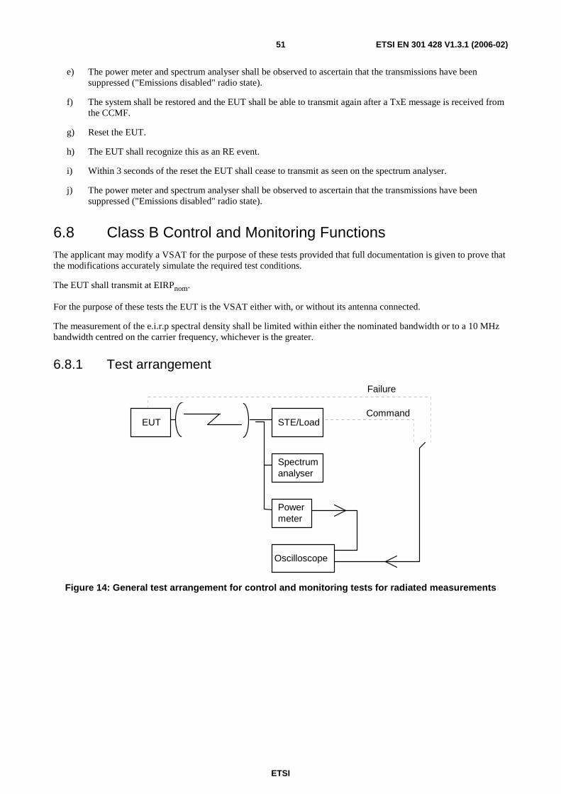
ETSI
ETSI EN 301 428 V1.3.1 (2006-02) 51
e) The power meter and spectrum analyser shall be observed to ascertain that the transmissions have been suppressed ("Emissions disabled" radio state).
f) The system shall be restored and the EUT shall be able to transmit again after a TxE message is received from the CCMF.
g) Reset the EUT.
h) The EUT shall recognize this as an RE event.
i) Within 3 seconds of the reset the EUT shall cease to transmit as seen on the spectrum analyser.
j) The power meter and spectrum analyser shall be observed to ascertain that the transmissions have been suppressed ("Emissions disabled" radio state).
6.8 Class B Control and Monitoring Functions The applicant may modify a VSAT for the purpose of these tests provided that full documentation is given to prove that the modifications accurately simulate the required test conditions.
The EUT shall transmit at EIRPnom.
For the purpose of these tests the EUT is the VSAT either with, or without its antenna connected.
The measurement of the e.i.r.p spectral density shall be limited within either the nominated bandwidth or to a 10 MHz bandwidth centred on the carrier frequency, whichever is the greater.
6.8.1 Test arrangement
STE/Load
Spectrumanalyser
Powermeter
Oscilloscope
EUTCommand
Failure
Figure 14: General test arrangement for control and monitoring tests for radiated measurements
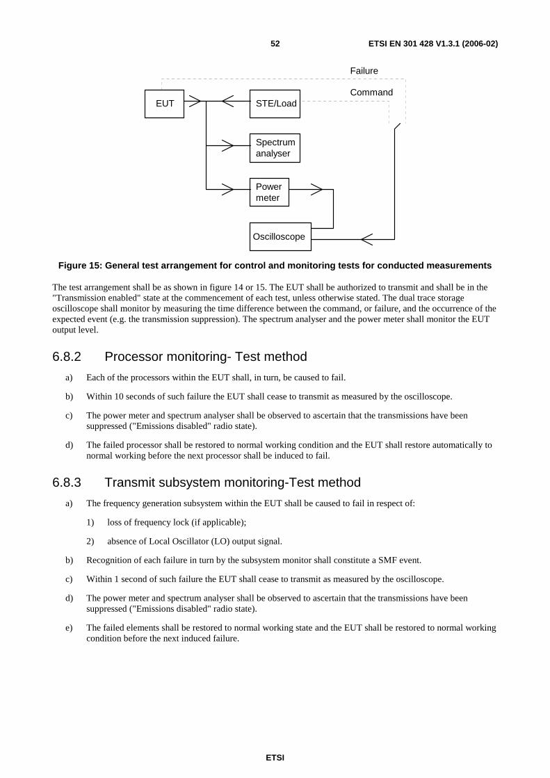
ETSI
ETSI EN 301 428 V1.3.1 (2006-02) 52
STE/LoadEUT
Spectrumanalyser
Powermeter
Oscilloscope
Command
Failure
Figure 15: General test arrangement for control and monitoring tests for conducted measurements
The test arrangement shall be as shown in figure 14 or 15. The EUT shall be authorized to transmit and shall be in the "Transmission enabled" state at the commencement of each test, unless otherwise stated. The dual trace storage oscilloscope shall monitor by measuring the time difference between the command, or failure, and the occurrence of the expected event (e.g. the transmission suppression). The spectrum analyser and the power meter shall monitor the EUT output level.
6.8.2 Processor monitoring- Test method
a) Each of the processors within the EUT shall, in turn, be caused to fail.
b) Within 10 seconds of such failure the EUT shall cease to transmit as measured by the oscilloscope.
c) The power meter and spectrum analyser shall be observed to ascertain that the transmissions have been suppressed ("Emissions disabled" radio state).
d) The failed processor shall be restored to normal working condition and the EUT shall restore automatically to normal working before the next processor shall be induced to fail.
6.8.3 Transmit subsystem monitoring-Test method
a) The frequency generation subsystem within the EUT shall be caused to fail in respect of:
1) loss of frequency lock (if applicable);
2) absence of Local Oscillator (LO) output signal.
b) Recognition of each failure in turn by the subsystem monitor shall constitute a SMF event.
c) Within 1 second of such failure the EUT shall cease to transmit as measured by the oscilloscope.
d) The power meter and spectrum analyser shall be observed to ascertain that the transmissions have been suppressed ("Emissions disabled" radio state).
e) The failed elements shall be restored to normal working state and the EUT shall be restored to normal working condition before the next induced failure.

ETSI
ETSI EN 301 428 V1.3.1 (2006-02) 53
6.8.4 Power-on/Reset-Test method
a) The EUT shall be switched off and the STE shall not transmit the CC;
b) the EUT shall be switched on;
c) the EUT shall not transmit during and after switching-on, and shall enter the "Non valid" state.
The events from a) to c) shall be displayed and verified with the oscilloscope and by measurement of the transmitted signal. If a manual reset function is implemented the following test shall be performed:
d) the EUT shall be restored to the "Initial phase" state and the STE shall transmit the CC;
e) the EUT shall remain in the "Initial phase" state;
f) the reset function shall be initiated;
g) within 1 seconds the EUT shall enter the "Non valid" state;
h) the EUT shall be restored to the "Initial phase" state and the STE shall transmit the CC as well as a TxE;
i) the EUT shall enter the "Transmission enabled" state;
j) the reset function shall be initiated;
k) within 1 second the EUT shall enter the "Non valid" state.
The event from e) to k) shall be displayed and verified with the oscilloscope and by measurement of the transmitted signal.
6.8.5 Control Channel (CC) reception-Test method
Tests shall simulate the following events:
- the CC has never been received by the EUT after power-on;
- the CC is lost by the EUT after reception of a Transmission Enable command;
- the CC is lost by the EUT without reception of a Transmission Enable command;
- the CC is being lost by the EUT and a call is initiated within the Time-Out period T1.
The Time-Out period T1 used in the tests shall be 10 seconds.
a) Case where the CC has never been received by the EUT after power-on:
a1) the EUT shall be switched off and the STE shall not transmit the CC;
a2) the EUT shall be switched on;
a3) the EUT shall remain in the "Non valid" state.
The events from a2) to a3) shall be displayed and verified with the oscilloscope and by measurement of the transmit signal.
b) Case where the CC is lost by the EUT after reception of a Transmission Enable command:
b1) the EUT shall be switched-on and the STE shall transmit the CC and a TxE;
b2) the EUT shall enter the "Initial phase" state and go, if applicable, to the "Transmission enabled" state;
b3) a transmission request shall be initiated from the EUT;
b4) the STE shall stop transmitting the CC;
b5) within the period T1 from event b4), the EUT shall enter the "Non valid" state.

ETSI
ETSI EN 301 428 V1.3.1 (2006-02) 54
The events from b1) to b5) shall be displayed and verified with the oscilloscope and by measurement of the transmitted signal.
c) Case where the CC is lost by the EUT without reception of a "Transmission enabled" state:
c1) the EUT shall be switched on and the STE shall transmit the CC;
c2) the EUT shall enter the "Initial phase" state;
c3) the STE shall stop transmitting the CC;
c4) the EUT shall enter in the "Non valid" state not later than T1;
c5) a transmission request shall be initiated and the EUT shall remain in the "Non valid" state.
The events from c2) to c5) shall be displayed and verified with the oscilloscope and by measurement of the transmitted signal.
d) Case where the CC is being lost by the EUT and a call is initiated within the T1 period:
d1) the EUT shall be switched on and the STE shall transmit the CC;
d2) the STE shall stop transmitting the CC;
d3) within the period T1 from d2), a transmission request shall be initiated from the EUT;
d4) the EUT may transmit but within the T1 period the EUT shall enter the "Non valid" state.
The events from d2) to d4) shall be displayed and verified with the oscilloscope and by measurement of the transmitted signal.
6.8.6 Network Control commands-Test method
The following tests shall be performed in sequence:
- transmission enable command;
- transmission disable command received in the "Transmission enabled" state;
- transmission disable command received in the "Initial phase" state.
a) Transmission enable command:
a1) the EUT shall be switched-on and the STE shall transmit the CC;
a2) the EUT shall enter the "Initial phase" state;
a3) a transmission request shall be initiated from the EUT, the EUT shall remain in the "Initial phase" state;
a4) the STE shall transmit an enable command to the EUT;
a5) a transmission request shall be initiated from the EUT;
a6) the EUT shall enter the "Transmission enabled" state and shall transmit.
The events from a2) to a6) shall be displayed and verified with the oscilloscope and by measurement of the transmitted signal.
b) Transmission disable command received in the "Transmission enabled" state:
b1) continue from a6);
b2) the STE shall transmit a disable command to the EUT;
b3) the EUT shall enter the "Transmission disabled" state within 1 second;
ETSI
ETSI EN 301 428 V1.3.1 (2006-02) 55
b4) a transmission request shall be initiated from the EUT;
b5) the EUT shall remain in the "Transmission disabled" state;
b6) the STE shall transmit an enable command;
b7) the EUT shall enter either the "Transmission enabled" state or the "Initial phase" state;
b8) if the EUT is in the "Transmission enable" state then the test continues with b11);
b9) the STE shall transmit a TxE command;
b10) the EUT shall enter the "Transmission enable" state;
b11) if a transmission request is not active any more then a new transmission request shall be initiated;
b12) the EUT shall transmit;
b13) the EUT transmission shall be terminated.
The events from b2) to b13) shall be displayed and verified with the oscilloscope and by measurement of the transmitted signal.
c) Transmission disable command received in the "Initial phase" state:
c1) the EUT shall be switched-on and the STE shall transmit the CC;
c2) the EUT shall enter the "Initial phase" state;
c3) the STE shall transmit a disable command to the EUT;
c4) the EUT shall enter the "Transmission disabled" state within 1 second;
c5) a transmission request shall be initiated from the EUT;
c6) the EUT shall remain in the "Transmission disabled" state;
c7) the STE shall transmit an enable command;
c8) the EUT shall enter either the "Transmission enabled" state or the "Initial phase" state;
c9) if the EUT is in the "Transmission enable" state then the test continues with c12);
c10) the STE shall transmit a TxE command;
c11) the EUT shall enter the "Transmission enable" state;
c12) if a transmission request is not active any more then a new transmission request shall be initiated;
c13) the EUT shall transmit;
c14) the EUT transmission shall be terminated.
The events from c2) to c14) shall be displayed and verified with the oscilloscope and by measurement of the transmitted signal.
ETSI
ETSI EN 301 428 V1.3.1 (2006-02) 56
6.8.7 Initial burst transmission-Test method
Tests shall be performed to simulate the following events:
- the CC is being received by the EUT;
- the CC has not been received by the EUT since power-on.
a) Case where the CC is being received:
a1) the EUT shall be switched-off and the STE shall transmit the CC;
a2) the EUT shall be switched-on;
a3) the EUT shall not transmit, except the initial bursts;
a4) it shall be verified that the specifications given in 5.6.2 are fulfilled.
The events from a2) to a4) shall be displayed and verified with the oscilloscope and by measurement of the transmitted signal.
b) Case where the CC has not been received by the EUT since power-on:
b1) the EUT shall be switched-off and the STE shall not transmit the CC;
b2) the EUT shall be switched-on;
b3) the EUT shall not transmit.
The events from b2) to b3) shall be displayed and verified with the oscilloscope and by measurement of the transmitted signal.
7 Test methods for modified VSAT
7.1 General The modifications of a VSAT may consist of the replacement of one or several of the following modules:
a) Antenna subsystem.
b) High Power Amplifier (HPA).
c) Up converter.
d) Low Noise Amplifier (LNA).
e) Down converter.
f) Modulator/demodulator (modem).
The intermediate and final results of the VSAT tests before modification shall be made available by the applicant.
ETSI
ETSI EN 301 428 V1.3.1 (2006-02) 57
7.2 Antenna subsystem replacement This clause is only applicable to passive antennas.
The following measurements made on the VSAT before modification shall not be repeated:
6.2.1.1.3 Procedure for off-axis spurious radiation up to 1 000 MHz.
6.2.1.2.1 Identification of the significant frequencies of spurious radiation.
6.2.1.2.2 Measurement of radiated power levels of identified spurious radiation (EUT without antenna).
6.2.1.2.3 Measurement of conducted spurious radiation at the antenna flange.
6.3.1.2.2 Method of measurement at the antenna flange of on-axis spurious radiation.
6.4.1.2 Transmit output power density.
6.5 Carrier suppression.
6.7 Class A Control and Monitoring Functions, if applicable.
6.8 Class B Control and Monitoring Functions, if applicable.
The results of these measurements shall be used as those of the unmodified VSAT and entered in the computation of these clauses.
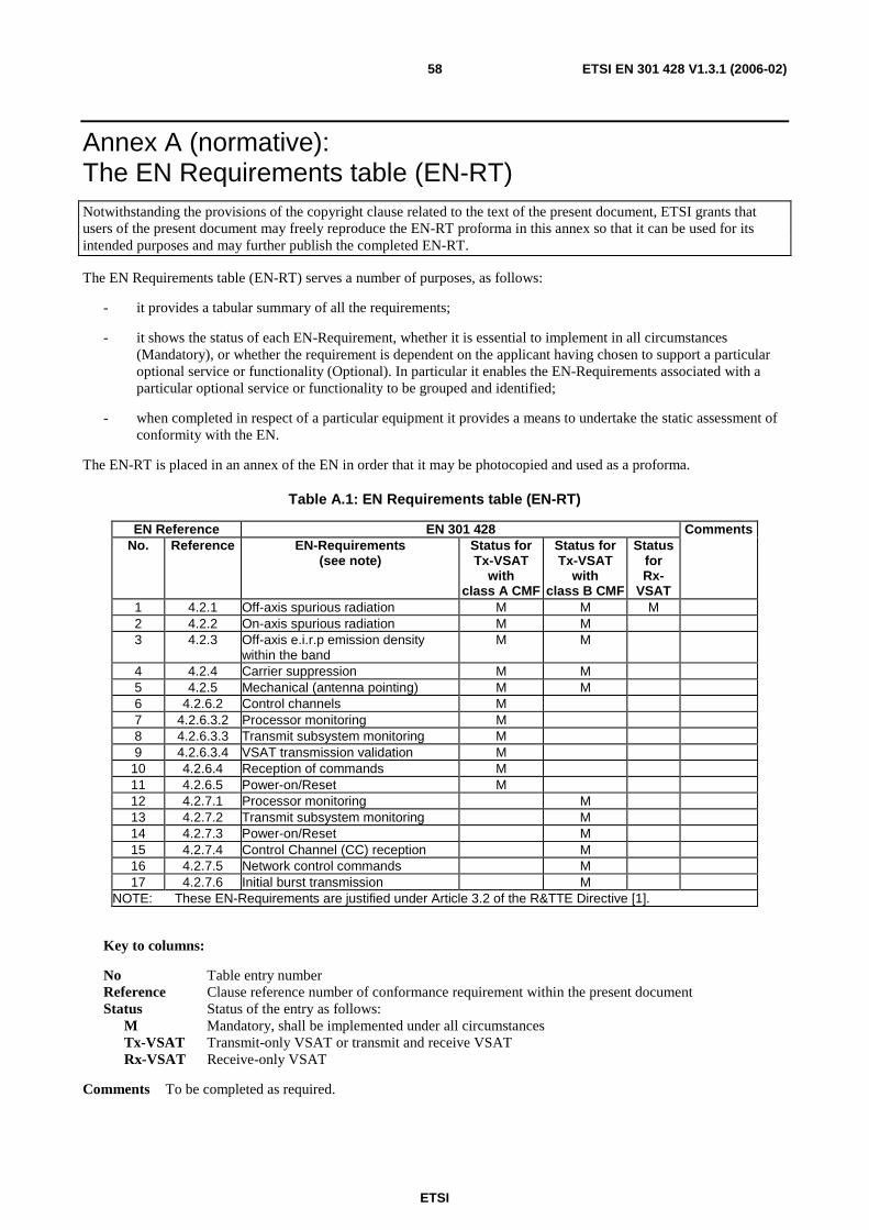
ETSI
ETSI EN 301 428 V1.3.1 (2006-02) 58
Annex A (normative): The EN Requirements table (EN-RT) Notwithstanding the provisions of the copyright clause related to the text of the present document, ETSI grants that users of the present document may freely reproduce the EN-RT proforma in this annex so that it can be used for its intended purposes and may further publish the completed EN-RT.
The EN Requirements table (EN-RT) serves a number of purposes, as follows:
- it provides a tabular summary of all the requirements;
- it shows the status of each EN-Requirement, whether it is essential to implement in all circumstances (Mandatory), or whether the requirement is dependent on the applicant having chosen to support a particular optional service or functionality (Optional). In particular it enables the EN-Requirements associated with a particular optional service or functionality to be grouped and identified;
- when completed in respect of a particular equipment it provides a means to undertake the static assessment of conformity with the EN.
The EN-RT is placed in an annex of the EN in order that it may be photocopied and used as a proforma.
Table A.1: EN Requirements table (EN-RT)
EN Reference EN 301 428 Comments No. Reference EN-Requirements
(see note) Status for Tx-VSAT
with class A CMF
Status for Tx-VSAT
with class B CMF
Status for Rx-
VSAT
1 4.2.1 Off-axis spurious radiation M M M 2 4.2.2 On-axis spurious radiation M M 3 4.2.3 Off-axis e.i.r.p emission density
within the band M M
4 4.2.4 Carrier suppression M M 5 4.2.5 Mechanical (antenna pointing) M M 6 4.2.6.2 Control channels M 7 4.2.6.3.2 Processor monitoring M 8 4.2.6.3.3 Transmit subsystem monitoring M 9 4.2.6.3.4 VSAT transmission validation M
10 4.2.6.4 Reception of commands M 11 4.2.6.5 Power-on/Reset M 12 4.2.7.1 Processor monitoring M 13 4.2.7.2 Transmit subsystem monitoring M 14 4.2.7.3 Power-on/Reset M 15 4.2.7.4 Control Channel (CC) reception M 16 4.2.7.5 Network control commands M 17 4.2.7.6 Initial burst transmission M
NOTE: These EN-Requirements are justified under Article 3.2 of the R&TTE Directive [1].
Key to columns:
No Table entry number Reference Clause reference number of conformance requirement within the present document Status Status of the entry as follows: M Mandatory, shall be implemented under all circumstances Tx-VSAT Transmit-only VSAT or transmit and receive VSAT Rx-VSAT Receive-only VSAT
Comments To be completed as required.

ETSI
ETSI EN 301 428 V1.3.1 (2006-02) 59
Annex B (informative): Pointing stability methodology This test based on a numerical analysis shall be performed in two stages.
a) In the first stage the effects of maximum wind speed shall be computed on the outdoor unit using a numerical analysis method (finite elements method by computer) taking into account the intrinsic properties of the materials.
b) In the second stage the computed loads shall be applied to the structure.
The purpose of the numerical analysis is twofold:
a) to show that the torque and the fields of force applied to the outdoor unit structure under nominated conditions do not reach the breakpoint limit of any element of the structure;
b) to compute equivalent static loads (force and torque) applied to the critical attachment points of the structures, e.g.:
- reflector-mounting legs fixing point;
- reflector-struts;
- LNB- struts.
Numerical analysis and load applications procedure:
a) The air related parameters, namely the kinetic viscosity used to calculate drags at the rims of the structure shall be calculated with the standard atmospheric environmental conditions (temperature = 293 K, air pressure = 1,013 × 105 Pascal).
b) The computations needed to derive the field of force and torque and the equivalent static stresses shall be carried out for each of the following variables:
- elevation angle: maximum and minimum;
- wind direction: in steps of 45° around the outdoor unit;
- wind speed: 180 km/h.
c) It shall be verified with the simulated results that break point limits are not exceeded for any self-contained element.
d) The calculated equivalent static loads shall be applied at any identified critical fixing point of the assembly.
e) Whilst the loads are applied the outdoor unit shall be observed and any distortion noted.
f) The test report shall contain the following information:
- the computation method used;
- description of the test equipment;
- description of the tests performed;
- results of the safety margin test;
- any signs of distortion observed;
- results of the measurements of the deviation of the antenna position;
- component deviation with respect to each other.
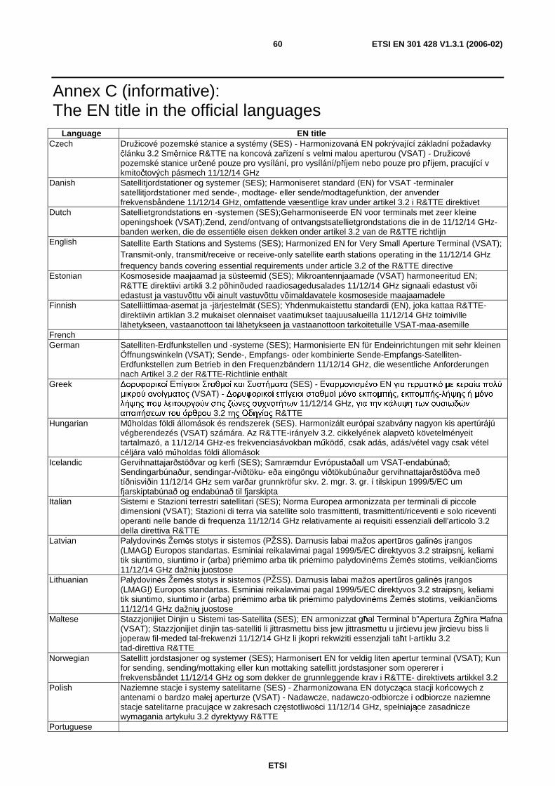
ETSI
ETSI EN 301 428 V1.3.1 (2006-02) 60
Annex C (informative): The EN title in the official languages
Language EN title Czech Družicové pozemské stanice a systémy (SES) - Harmonizovaná EN pokrývající základní požadavky
článku 3.2 Směrnice R&TTE na koncová zařízení s velmi malou aperturou (VSAT) - Družicové pozemské stanice určené pouze pro vysílání, pro vysílání/příjem nebo pouze pro příjem, pracující v kmitočtových pásmech 11/12/14 GHz
Danish Satellitjordstationer og systemer (SES); Harmoniseret standard (EN) for VSAT -terminaler satellitjordstationer med sende-, modtage- eller sende/modtagefunktion, der anvender frekvensbåndene 11/12/14 GHz, omfattende væsentlige krav under artikel 3.2 i R&TTE direktivet
Dutch Satellietgrondstations en -systemen (SES);Geharmoniseerde EN voor terminals met zeer kleine openingshoek (VSAT);Zend, zend/ontvang of ontvangstsatellietgrondstations die in de 11/12/14 GHz-banden werken, die de essentiële eisen dekken onder artikel 3.2 van de R&TTE richtlijn
English Satellite Earth Stations and Systems (SES); Harmonized EN for Very Small Aperture Terminal (VSAT); Transmit-only, transmit/receive or receive-only satellite earth stations operating in the 11/12/14 GHz frequency bands covering essential requirements under article 3.2 of the R&TTE directive
Estonian Kosmoseside maajaamad ja süsteemid (SES); Mikroantennjaamade (VSAT) harmoneeritud EN; R&TTE direktiivi artikli 3.2 põhinõuded raadiosagedusalades 11/12/14 GHz signaali edastust või edastust ja vastuvõttu või ainult vastuvõttu võimaldavatele kosmoseside maajaamadele
Finnish Satelliittimaa-asemat ja -järjestelmät (SES); Yhdenmukaistettu standardi (EN), joka kattaa R&TTE-direktiivin artiklan 3.2 mukaiset olennaiset vaatimukset taajuusalueilla 11/12/14 GHz toimiville lähetykseen, vastaanottoon tai lähetykseen ja vastaanottoon tarkoitetuille VSAT-maa-asemille
French German Satelliten-Erdfunkstellen und -systeme (SES); Harmonisierte EN für Endeinrichtungen mit sehr kleinen
Öffnungswinkeln (VSAT); Sende-, Empfangs- oder kombinierte Sende-Empfangs-Satelliten-Erdfunkstellen zum Betrieb in den Frequenzbändern 11/12/14 GHz, die wesentliche Anforderungen nach Artikel 3.2 der R&TTE-Richtlinie enthält
Greek ∆ορυφορικοί Επίγειοι Σταθµοί και Συστήµατα (SES) - Εναρµονισµένο EN για τερµατικό µε κεραία πολύ µικρού ανοίγµατος (VSAT) - ∆ορυφορικοί επίγειοι σταθµοί µόνο εκποµπής, εκποµπής-λήψης ή µόνο λήψης που λειτουργούν στις ζώνες συχνοτήτων 11/12/14 GHz, για την κάλυψη των ουσιωδών απαιτήσεων του άρθρου 3.2 της Οδηγίας R&TTE
Hungarian Műholdas földi állomások és rendszerek (SES). Harmonizált európai szabvány nagyon kis apertúrájú végberendezés (VSAT) számára. Az R&TTE-irányelv 3.2. cikkelyének alapvető követelményeit tartalmazó, a 11/12/14 GHz-es frekvenciasávokban működő, csak adás, adás/vétel vagy csak vétel céljára való műholdas földi állomások
Icelandic Gervihnattajarðstöðvar og kerfi (SES); Samræmdur Evrópustaðall um VSAT-endabúnað; Sendingarbúnaður, sendingar-/viðtöku- eða eingöngu viðtökubúnaður gervihnattajarðstöðva með tíðnisviðin 11/12/14 GHz sem varðar grunnkröfur skv. 2. mgr. 3. gr. í tilskipun 1999/5/EC um fjarskiptabúnað og endabúnað til fjarskipta
Italian Sistemi e Stazioni terrestri satellitari (SES); Norma Europea armonizzata per terminali di piccole dimensioni (VSAT); Stazioni di terra via satellite solo trasmittenti, trasmittenti/riceventi e solo riceventi operanti nelle bande di frequenza 11/12/14 GHz relativamente ai requisiti essenziali dell'articolo 3.2 della direttiva R&TTE
Latvian Palydovinės Žemės stotys ir sistemos (PŽSS). Darnusis labai mažos apertūros galinės įrangos (LMAGĮ) Europos standartas. Esminiai reikalavimai pagal 1999/5/EC direktyvos 3.2 straipsnį, keliami tik siuntimo, siuntimo ir (arba) priėmimo arba tik priėmimo palydovinėms Žemės stotims, veikiančioms 11/12/14 GHz dažnių juostose
Lithuanian Palydovinės Žemės stotys ir sistemos (PŽSS). Darnusis labai mažos apertūros galinės įrangos (LMAGĮ) Europos standartas. Esminiai reikalavimai pagal 1999/5/EC direktyvos 3.2 straipsnį, keliami tik siuntimo, siuntimo ir (arba) priėmimo arba tik priėmimo palydovinėms Žemės stotims, veikiančioms 11/12/14 GHz dažnių juostose
Maltese Stazzjonijiet Dinjin u Sistemi tas-Satellita (SES); EN armonizzat għal Terminal b"Apertura Żgħira Ħafna (VSAT); Stazzjonijiet dinjin tas-satelliti li jittrasmettu biss jew jittrasmettu u jirċievu jew jirċievu biss li joperaw fil-meded tal-frekwenzi 11/12/14 GHz li jkopri rekwiżiti essenzjali taħt l-artiklu 3.2 tad-direttiva R&TTE
Norwegian Satellitt jordstasjoner og systemer (SES); Harmonisert EN for veldig liten apertur terminal (VSAT); Kun for sending, sending/mottaking eller kun mottaking satellitt jordstasjoner som opererer i frekvensbåndet 11/12/14 GHz og som dekker de grunnleggende krav i R&TTE- direktivets artikkel 3.2
Polish Naziemne stacje i systemy satelitarne (SES) - Zharmonizowana EN dotycząca stacji końcowych z antenami o bardzo małej aperturze (VSAT) - Nadawcze, nadawczo-odbiorcze i odbiorcze naziemne stacje satelitarne pracujące w zakresach częstotliwości 11/12/14 GHz, spełniające zasadnicze wymagania artykułu 3.2 dyrektywy R&TTE
Portuguese
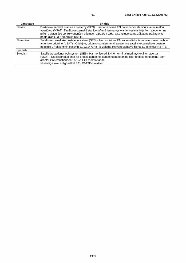
ETSI
ETSI EN 301 428 V1.3.1 (2006-02) 61
Language EN title Slovak Družicové zemské stanice a systémy (SES). Harmonizovaná EN na koncovú stanicu s veľmi malou
apertúrou (VSAT). Družicové zemské stanice určené len na vysielanie, vysielanie/príjem alebo len na príjem, pracujúce vo frekvenčných pásmach 11/12/14 GHz, vzťahujúce sa na základné požiadavky podľa článku 3.2 smernice R&TTE
Slovenian Satelitske zemeljske postaje in sistemi (SES) - Harmonizirani EN za satelitske terminale z zelo majhno antensko odprtino (VSAT) - Oddajne, oddajno-sprejemne ali sprejemne satelitske zemeljske postaje, delujoče v frekvenčnih pasovih 11/12/14 GHz - ki zajema bistvene zahteve člena 3.2 direktive R&TTE
Spanish Swedish Satellitjordstationer och system (SES); Harmoniserad EN för terminal med mycket liten apertur
(VSAT); Satellitjordstationer för endast sändning, sändning/mottagning eller endast mottagning, som arbetar i frekvensbanden 11/12/14 GHz omfattande väsentliga krav enligt artikel 3.2 i R&TTE-direktivet
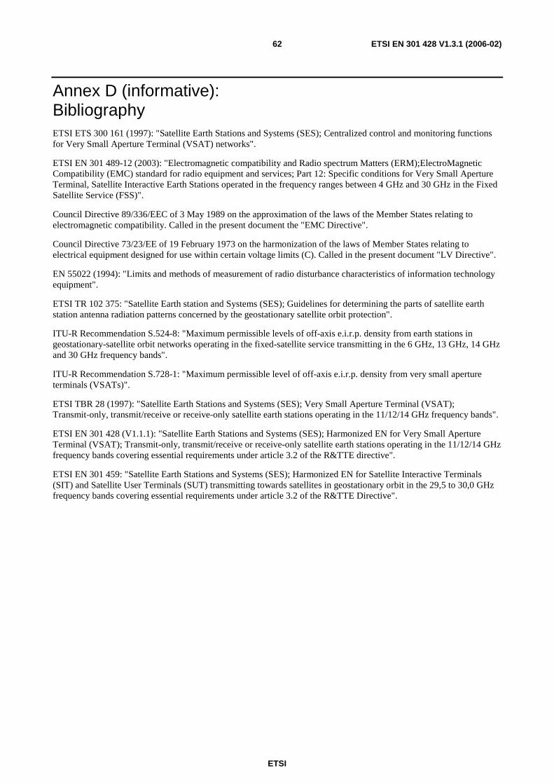
ETSI
ETSI EN 301 428 V1.3.1 (2006-02) 62
Annex D (informative): Bibliography ETSI ETS 300 161 (1997): "Satellite Earth Stations and Systems (SES); Centralized control and monitoring functions for Very Small Aperture Terminal (VSAT) networks".
ETSI EN 301 489-12 (2003): "Electromagnetic compatibility and Radio spectrum Matters (ERM);ElectroMagnetic Compatibility (EMC) standard for radio equipment and services; Part 12: Specific conditions for Very Small Aperture Terminal, Satellite Interactive Earth Stations operated in the frequency ranges between 4 GHz and 30 GHz in the Fixed Satellite Service (FSS)".
Council Directive 89/336/EEC of 3 May 1989 on the approximation of the laws of the Member States relating to electromagnetic compatibility. Called in the present document the "EMC Directive".
Council Directive 73/23/EE of 19 February 1973 on the harmonization of the laws of Member States relating to electrical equipment designed for use within certain voltage limits (C). Called in the present document "LV Directive".
EN 55022 (1994): "Limits and methods of measurement of radio disturbance characteristics of information technology equipment".
ETSI TR 102 375: "Satellite Earth station and Systems (SES); Guidelines for determining the parts of satellite earth station antenna radiation patterns concerned by the geostationary satellite orbit protection".
ITU-R Recommendation S.524-8: "Maximum permissible levels of off-axis e.i.r.p. density from earth stations in geostationary-satellite orbit networks operating in the fixed-satellite service transmitting in the 6 GHz, 13 GHz, 14 GHz and 30 GHz frequency bands".
ITU-R Recommendation S.728-1: "Maximum permissible level of off-axis e.i.r.p. density from very small aperture terminals (VSATs)".
ETSI TBR 28 (1997): "Satellite Earth Stations and Systems (SES); Very Small Aperture Terminal (VSAT); Transmit-only, transmit/receive or receive-only satellite earth stations operating in the 11/12/14 GHz frequency bands".
ETSI EN 301 428 (V1.1.1): "Satellite Earth Stations and Systems (SES); Harmonized EN for Very Small Aperture Terminal (VSAT); Transmit-only, transmit/receive or receive-only satellite earth stations operating in the 11/12/14 GHz frequency bands covering essential requirements under article 3.2 of the R&TTE directive".
ETSI EN 301 459: "Satellite Earth Stations and Systems (SES); Harmonized EN for Satellite Interactive Terminals (SIT) and Satellite User Terminals (SUT) transmitting towards satellites in geostationary orbit in the 29,5 to 30,0 GHz frequency bands covering essential requirements under article 3.2 of the R&TTE Directive".
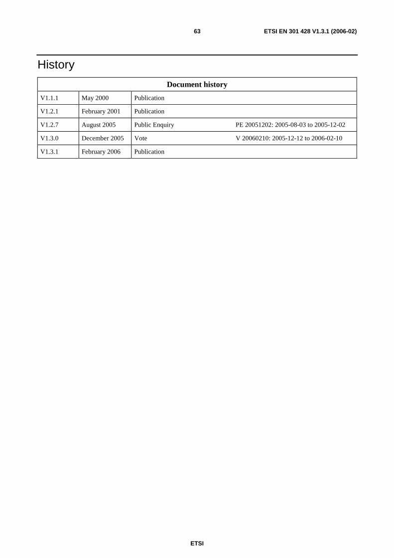
ETSI
ETSI EN 301 428 V1.3.1 (2006-02) 63
History
Document history
V1.1.1 May 2000 Publication
V1.2.1 February 2001 Publication
V1.2.7 August 2005 Public Enquiry PE 20051202: 2005-08-03 to 2005-12-02
V1.3.0 December 2005 Vote V 20060210: 2005-12-12 to 2006-02-10
V1.3.1 February 2006 Publication