Embed Size (px)
Citation preview
EMC® ViPR SRMVersion 3.7
SolutionPack Installation and ConfigurationGuideP/N 302-002-357
REV 06

Copyright © 2015-2016 EMC Corporation. All rights reserved. Published in the USA.
Published February, 2016
EMC believes the information in this publication is accurate as of its publication date. The information is subject to changewithout notice.
The information in this publication is provided as is. EMC Corporation makes no representations or warranties of any kind withrespect to the information in this publication, and specifically disclaims implied warranties of merchantability or fitness for aparticular purpose. Use, copying, and distribution of any EMC software described in this publication requires an applicablesoftware license.
EMC², EMC, and the EMC logo are registered trademarks or trademarks of EMC Corporation in the United States and othercountries. All other trademarks used herein are the property of their respective owners.
For the most up-to-date regulatory document for your product line, go to EMC Online Support (https://support.emc.com).
EMC CorporationHopkinton, Massachusetts 01748-91031-508-435-1000 In North America 1-866-464-7381www.EMC.com
2 EMC ViPR SRM 3.7 SolutionPack Installation and Configuration Guide

11
13
15
Getting started 17
What are SolutionPacks?...............................................................................18Licenses........................................................................................................19Browse and install.........................................................................................19Reconfigure an installed SolutionPack.......................................................... 21Update SolutionPacks................................................................................... 23Where to find the latest SolutionPack software..............................................23ViPR SRM and SolutionPack privileges.......................................................... 24
SolutionPack for Block Chargeback 31
Overview....................................................................................................... 32Chargeable and non-chargeable metrics .......................................................32Installing the SolutionPack............................................................................33Running the chargeback preprocessor task manually.................................... 35Enable collecting component level metrics for a limited set of hosts..............36Limitations ................................................................................................... 36
SolutionPack for Brocade FC Switch 39
Overview....................................................................................................... 40Brocade switch and SMI agent configuration................................................. 41
Configuring Brocade SMI Agents...................................................... 41Configuring Brocade switches for alert consolidation....................... 41Configuring Brocade switches for SNMP discovery........................... 42
Installing the SolutionPack............................................................................42Passive host discovery configuration options................................................ 45
SolutionPack for Cisco MDS 47
Overview....................................................................................................... 48Performing pre-configuration tasks................................................................48
Known issue with user-defined roles................................................ 49Configuring switches for SNMPv1 and SNMPv2c............................................49Configuring switches for SNMPv3.................................................................. 50Configuring Cisco switches for alert consolidation.........................................51Installing the SolutionPack............................................................................51Enabling passive host discovery through Generic-SNMP................................52Enable and edit customized zone naming patterns........................................53Limitations....................................................................................................53
Figures
Tables
Preface
Chapter 1
Chapter 2
Chapter 3
Chapter 4
CONTENTS
EMC ViPR SRM 3.7 SolutionPack Installation and Configuration Guide 3

SolutionPack for Cisco UCS 55
Overview....................................................................................................... 56Configuring the UCS Manager........................................................................56Installing the SolutionPack............................................................................56Importing the new database schema.............................................................58
SolutionPack for Converged Infrastructure 61
Overview....................................................................................................... 62Preparing Converged Infrastructure............................................................... 62Installing the SolutionPack............................................................................62
SolutionPack for EMC Atmos 65
Overview....................................................................................................... 66Installing the SolutionPack............................................................................66Limitations....................................................................................................67
SolutionPack for EMC Centera 69
Overview....................................................................................................... 70Preparing Centera arrays for discovery and data collection............................ 70
Configuring Centera arrays for alert consolidation............................ 70Installing the SolutionPack............................................................................71Limitations....................................................................................................72
SolutionPack for EMC Data Domain 73
Overview....................................................................................................... 74Preparing EMC Data Domain for discovery and data collection.......................74Configuring Data Domain devices for alert consolidation............................... 74Installing the SolutionPack ...........................................................................75Discover the SNMP Collector......................................................................... 76
SolutionPack for EMC Data Protection Advisor 77
Overview....................................................................................................... 78Installing the SolutionPack............................................................................78Verifying scheduled reports in DPA................................................................80Troubleshooting report generation errors...................................................... 80Limitations....................................................................................................80
SolutionPack for EMC ECS 81
Overview....................................................................................................... 82Installing the SolutionPack for EMC ECS........................................................ 85Remove old ECS hosts from the Physical Host SP.......................................... 87Expand ECS...................................................................................................87Limitations....................................................................................................88
SolutionPack for EMC Host Interface 91
Overview....................................................................................................... 92Installing the SolutionPack............................................................................92Recommendations........................................................................................ 93
Chapter 5
Chapter 6
Chapter 7
Chapter 8
Chapter 9
Chapter 10
Chapter 11
Chapter 12
CONTENTS
4 EMC ViPR SRM 3.7 SolutionPack Installation and Configuration Guide

Limitations....................................................................................................94
SolutionPack for EMC Isilon 95
Overview....................................................................................................... 96Installing the SolutionPack............................................................................97Updating SolutionPack alert definitions........................................................ 98Limitations....................................................................................................98
SolutionPack for EMC M&R Health 99
Overview..................................................................................................... 100Installing the SolutionPack..........................................................................100
SolutionPack for EMC Recoverpoint 103
Overview..................................................................................................... 104Installing the SolutionPack..........................................................................104
SolutionPack for EMC ViPR Controller 107
Overview..................................................................................................... 108Installing the SolutionPack for EMC ViPR Controller..................................... 109
SolutionPack for EMC VMAX 113
Overview..................................................................................................... 114Configuring the access credentials.............................................................. 115Preparing EMC VMAX for discovery and data collection ...............................115
VMAX3 discovery scenario ............................................................ 115VMAX/DMX discovery scenario ......................................................117Creating VMAX3/VMAX collectors for discovery of Symmetrix arrays(local discovery configuration)....................................................... 118Solutions Enabler proxy scenario .................................................. 119Configuring VMAX arrays for consolidation of availability alerts......120
Installing the SolutionPack..........................................................................121Troubleshooting Discovery Center connectivity failures............................... 124
Viewing the Test button test results................................................124Understanding the test messages.................................................. 126
Updating SolutionPack alert definitions...................................................... 127Configuring Solutions Enabler client access for VMAX................................. 128
Configuring host access................................................................. 129Adding client hosts to existing SYMAUTH configuration..................129Enabling client authorization..........................................................130Validating Symmetrix access controls............................................ 131Limitation: some alerts not displayed.............................................131
Resolving SMI-S Provider port conflicts........................................................132Limitations..................................................................................................132
SolutionPack for EMC VNX 135
Overview..................................................................................................... 136Preparing your VNX for discovery and data collection.................................. 137
Configuring simple authentication................................................. 137Unisphere security file authentication............................................ 137
Chapter 13
Chapter 14
Chapter 15
Chapter 16
Chapter 17
Chapter 18
CONTENTS
EMC ViPR SRM 3.7 SolutionPack Installation and Configuration Guide 5
Configuring VNX arrays for file storage discovery............................ 138Installing the SolutionPack..........................................................................139Updating SolutionPack alert definitions...................................................... 141Changing VNX object credentials using Discovery Center.............................142Resolving collector communication errors................................................... 143Limitations..................................................................................................144
SolutionPack for EMC VPLEX 145
Overview..................................................................................................... 146Installing the SolutionPack..........................................................................147
Troubleshooting performance data collection issues......................149Configure VPLEX SNMP................................................................................149Limitations..................................................................................................149
SolutionPack for EMC ScaleIO 151
Overview..................................................................................................... 152Installing the SolutionPack for EMC ScaleIO................................................ 153Limitations..................................................................................................154
SolutionPack for EMC XtremIO 155
Overview..................................................................................................... 156Installing the SolutionPack..........................................................................156Limitations..................................................................................................158
SolutionPack for Hitachi Device Manager 159
Overview..................................................................................................... 160Preparing Hitachi Device Manager for discovery and data collection............160Installing the SolutionPack..........................................................................161Troubleshooting Device Manager collection................................................ 163Embedded Performance Collection..............................................................163
Enabling the SMI-S certificate........................................................ 163Restarting the SMI-S provider.........................................................163Enabling performance monitoring in Storage Navigator.................. 164Configuring embedded performance monitoring............................ 164Troubleshooting the Embedded SMI-S Provider..............................165
Limitations..................................................................................................166
SolutionPack for HP 3PAR Storeserv 167
Overview..................................................................................................... 168Preparing your system for discovery and data collection..............................168Installing the SolutionPack..........................................................................169
SolutionPack for HP EVA 171
Overview..................................................................................................... 172Preparing your HP EVA system for discovery and data collection..................172Installing the SolutionPack..........................................................................172
SolutionPack for HP Storageworks XP 175
Chapter 19
Chapter 20
Chapter 21
Chapter 22
Chapter 23
Chapter 24
Chapter 25
CONTENTS
6 EMC ViPR SRM 3.7 SolutionPack Installation and Configuration Guide
Overview..................................................................................................... 176Installing the SolutionPack..........................................................................176Troubleshooting Device Manager collection................................................ 179Embedded Performance Collection..............................................................179
Enabling the SMI-S certificate........................................................ 179Restarting the SMI-S provider.........................................................179Enabling performance monitoring in Storage Navigator.................. 180Configuring embedded performance monitoring............................ 180Troubleshooting the Embedded SMI-S Provider..............................181
SolutionPack for IBM DS 183
Overview..................................................................................................... 184Preparing your IBM DS system for discovery and data collection..................184Installing the SolutionPack..........................................................................185
SolutionPack for IBM LPAR 187
Overview..................................................................................................... 188Configuring VIO for discovery...................................................................... 188
Configuring sudo for VIO Server and VIO Client host discovery........189Configuring PowerBroker for VIO Server and VIO Client discovery... 190Generating a public and private key pair........................................ 192Importing a private key into the Collector ...................................... 192
Verify adapter IDs in NPIV configuration...................................................... 193Installing the SolutionPack and configuring the devices for discovery..........193Using Discovery Center to discover the VIO Servers and Clients................... 194Setting up key-based discovery for HMC......................................................195Using Discovery Center to discover an HMC................................................. 195SolutionPack Reconfiguration..................................................................... 195
SolutionPack for IBM SAN Volume Controller/Storwize 197
Overview..................................................................................................... 198Preparing for discovery and data collection................................................. 198Installing the SolutionPack..........................................................................199Limitations..................................................................................................200
SolutionPack for IBM XIV 201
Overview..................................................................................................... 202Preparing your IBM XIV system for discovery and data collection................. 202Installing the SolutionPack..........................................................................203Limitations..................................................................................................204Known problems ........................................................................................ 205
SolutionPack for Microsoft Hyper-V 207
Overview..................................................................................................... 208Configuring credentials for SolutionPack for Microsoft Hyper-V....................208Requirements for data collection.................................................................208Installing the SolutionPack..........................................................................209Using a test script to query WMI objects...................................................... 210
SolutionPack for Microsoft SQL Server 211
Chapter 26
Chapter 27
Chapter 28
Chapter 29
Chapter 30
Chapter 31
CONTENTS
EMC ViPR SRM 3.7 SolutionPack Installation and Configuration Guide 7
Overview..................................................................................................... 212User privilege requirements for SolutionPack for Microsoft SQL...................212Configuring the SolutionPack with an unprivileged account.........................213Installing the SolutionPack for Microsoft SQL.............................................. 214Limitations for Microsoft SQL Server............................................................215
SolutionPack for NetApp Filer 217
Overview..................................................................................................... 218Configuring access credentials....................................................................218Preparing NetApp Filer for discovery and data collection..............................219Installing the SolutionPack..........................................................................219Supported use cases and limitations.......................................................... 220
SolutionPack for Oracle Database 223
Overview..................................................................................................... 224Installing the SolutionPack..........................................................................224Topology for the SolutionPack for Oracle Database......................................226Configuring the SolutionPack with an unprivileged account.........................226Discovery Center requirements....................................................................227Configuring sudo rights for ASM scripts....................................................... 227Limitations..................................................................................................228
SolutionPack for Oracle MySQL Database 229
Overview..................................................................................................... 230Preparing MySQL database for discovery and data collection ..................... 230Installing the SolutionPack .........................................................................231
SolutionPack for Physical Hosts 233
Overview..................................................................................................... 234Preparing your hosts for discovery and data collection................................ 234
Guidelines for hostnames and IP addresses...................................234Guidelines for SNIA libraries and HBA drivers................................. 234Windows host configuration for discovery and data collection........235Unix host configuration for discovery and data collection...............245Configuring ESX hosts to collect PowerPath metrics....................... 250Configuring hosts to collect PowerPath metrics.............................. 251
Installing the SolutionPack and configuring devices for discovery............... 252SolutionPack reconfiguration...................................................................... 254Recommendations...................................................................................... 254Limitations..................................................................................................254
SolutionPack for Storage Compliance 257
Overview..................................................................................................... 258Where to find the latest SolutionPack software............................................258Installing the SolutionPack..........................................................................258
SolutionPack for VI VirtualWisdom 261
Overview..................................................................................................... 262Preparing VI VirtualWisdom.........................................................................262
Chapter 32
Chapter 33
Chapter 34
Chapter 35
Chapter 36
Chapter 37
CONTENTS
8 EMC ViPR SRM 3.7 SolutionPack Installation and Configuration Guide

Connecting to multiple VirtualWisdom Portal Servers..................... 263Installing the SolutionPack..........................................................................264
SolutionPack for VMware vCenter 267
Overview..................................................................................................... 268Configuring the SolutionPack to collect Powerpath data.............................. 268Installing this SolutionPack.........................................................................268Post-install requirements............................................................................ 271Limitations..................................................................................................271
Discovery Center 273
Adding devices to discovery groups............................................................ 274
Troubleshooting 277
Confirming report creation...........................................................................278What to do if data does not appear in any reports........................................278
Running a scheduled task to import data into reports.....................278What to do if data does not appear in some reports.....................................278
Searching for metrics in the database............................................ 279External storage capacity is counted more than once in capacity reports..... 279Authorization fails for passwords having special characters........................ 279Troubleshooting discovery issues, slow reports, and missing data ............. 279Viewing collector errors in the Collector-Manager log files........................... 280
Chapter 38
Chapter 39
Chapter 40
CONTENTS
EMC ViPR SRM 3.7 SolutionPack Installation and Configuration Guide 9

CONTENTS
10 EMC ViPR SRM 3.7 SolutionPack Installation and Configuration Guide

Sample sudoers file for Linux OS................................................................................. 190Verify that the host is ready for discovery with HTTP.....................................................241Set Negotiate authtype................................................................................................ 241Sample sudoers file for Linux OS................................................................................. 247ESX PowerPath metrics collection................................................................................ 251
12345
FIGURES
EMC ViPR SRM 3.7 SolutionPack Installation and Configuration Guide 11

FIGURES
12 EMC ViPR SRM 3.7 SolutionPack Installation and Configuration Guide

ViPR SRM and SolutionPack privilege levels...................................................................24Shared disk with no storage used ................................................................................. 33Shared disk with some storage used............................................................................. 33Sample zone naming patterns....................................................................................... 45Sample output of show snmp user command................................................................ 50Sample zone naming patterns....................................................................................... 53Known problems..........................................................................................................205Supported use cases and limitations...........................................................................220Allowed discovery types.............................................................................................. 236Host Configuration utility command options................................................................ 240
12345678910
TABLES
EMC ViPR SRM 3.7 SolutionPack Installation and Configuration Guide 13

TABLES
14 EMC ViPR SRM 3.7 SolutionPack Installation and Configuration Guide
Preface
Note
For the latest ViPR SRM documentation, go to the EMC Community Network.
Related documentationThe following EMC publications provide additional ViPR SRM information and areavailable on EMC Online Support:
l ViPR SRM SolutionPack Release NotesThis publication contains known issues and supplemental information for eachSolutionPack.
l EMC M&R Release NotesThis publication contains known issues and supplemental information related to theM&R platform, which provides the foundation for ViPR SRM.
l ViPR SRM Support MatrixThis publication lists SolutionPack compatibility, prerequisites, data collectioninterfaces, and ports.
Your commentsYour suggestions will help us continue to improve the accuracy, organization, and overallquality of the user publications. Send your opinions of this document to SRMDocumentation.
EMC ViPR SRM 3.7 SolutionPack Installation and Configuration Guide 15

Preface
16 EMC ViPR SRM 3.7 SolutionPack Installation and Configuration Guide

CHAPTER 1
Getting started
l What are SolutionPacks?.......................................................................................18l Licenses................................................................................................................19l Browse and install.................................................................................................19l Reconfigure an installed SolutionPack...................................................................21l Update SolutionPacks........................................................................................... 23l Where to find the latest SolutionPack software......................................................23l ViPR SRM and SolutionPack privileges...................................................................24
Getting started 17
What are SolutionPacks?Understand the role of SolutionPacks in the ViPR SRM product and gain a high-levelunderstanding of how they are licensed, installed, reconfigured, and updated.
A SolutionPack is an installable application that provides data collection and reportingcapabilities for specific entities in your infrastructure. The SolutionPacks support EMCstorage systems along with many common third-party storage infrastructure components.
The SolutionPacks provide asset-specific support to an enterprise installation. Yourorganization purchases licenses to provide visibility into only those assets that exist inits installed infrastructure.
With a new installation, most SolutionPacks are initially available for you to try for 30days using a trial license. You can obtain a permanent license that enables any numberand combination of available SolutionPacks in your environment.
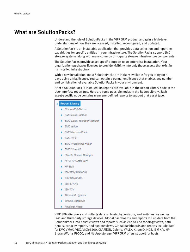
After a SolutionPack is installed, its reports are available in the Report Library node in theUser Interface report tree. Here are some possible nodes in the Report Library. Eachasset-specific node contains many pre-defined reports to support that asset type.
ViPR SRM discovers and collects data on hosts, hypervisors, and switches, as well asEMC and third-party storage devices. Global dashboards and reports roll up data from theSolutionPacks into holistic views and reports such as end-to-end topology views, pathdetails, capacity reports, and explore views. Global dashboards and reports include datafor EMC VMAX, VNX, VNXe3200, CLARiiON, Celerra, VPLEX, XtremIO, HDS, IBM XIV, HPStorageWorks P9000, and NetApp storage. ViPR SRM offers support for hosts,
Getting started
18 EMC ViPR SRM 3.7 SolutionPack Installation and Configuration Guide
hypervisors, switches, and arrays using SolutionPacks that provide in-depth reporting forthe individual objects. Most of the available SolutionPack data is rolled up into the globalreports and dashboards, although not all are included. As EMC normalizes theSolutionPack data, EMC will continue to add data from those SolutionPacks to the globalreports and dashboard views.
LicensesYou must have a license to install SolutionPacks.
With the installation of ViPR SRM, all SolutionPacks are initially available for you to try for30 days using a trial license.
A permanent license can enable any number and combination of SolutionPacks for anenvironment.
To add SolutionPacks to an initial license, see your EMC Account representative. They canhelp issue temporary licenses for evaluation purposes or set up the sale of additionalSolutionPacks. New entitlements are added to the existing license. To obtain the updatedlicense, download it from the license portal.
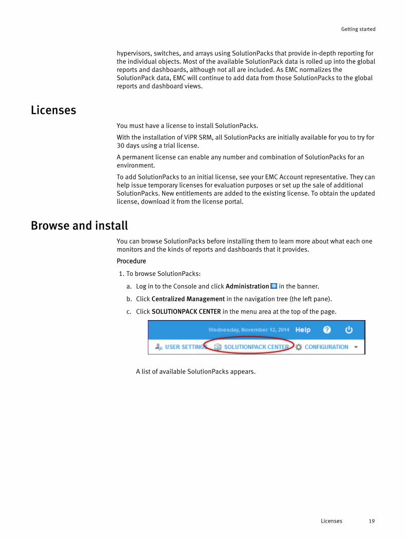
Browse and installYou can browse SolutionPacks before installing them to learn more about what each onemonitors and the kinds of reports and dashboards that it provides.
Procedure
1. To browse SolutionPacks:
a. Log in to the Console and click Administration in the banner.
b. Click Centralized Management in the navigation tree (the left pane).
c. Click SOLUTIONPACK CENTER in the menu area at the top of the page.
A list of available SolutionPacks appears.
Getting started
Licenses 19
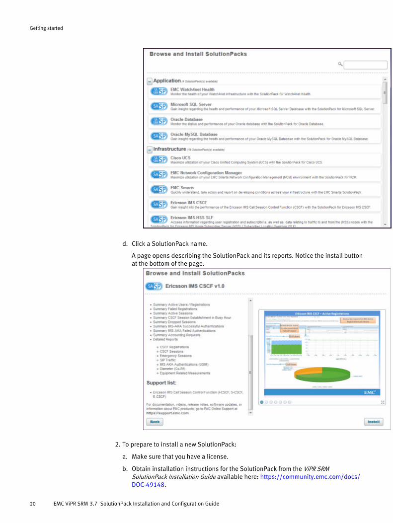
d. Click a SolutionPack name.
A page opens describing the SolutionPack and its reports. Notice the install buttonat the bottom of the page.
2. To prepare to install a new SolutionPack:
a. Make sure that you have a license.
b. Obtain installation instructions for the SolutionPack from the ViPR SRMSolutionPack Installation Guide available here: https://community.emc.com/docs/DOC-49148.
Getting started
20 EMC ViPR SRM 3.7 SolutionPack Installation and Configuration Guide
Each chapter in that guide describes installation and configuration steps forintegrating a particular SolutionPack into an installed ViPR SRM environment.
3. To install a new SolutionPack:
a. Navigate to the SolutionPack page as described in Step 1.
b. Click Install on the description page to start the installation.
c. Continue by following instructions in the installation guide.
Reconfigure an installed SolutionPackYou can change the configuration options that are initially set during a SolutionPackinstallation.
To reconfigure a SolutionPack:
Procedure
1. Log in to the Console and click Administration in the banner.
2. Click Centralized Management in the navigation tree (the left pane).
A new browser tab opens.
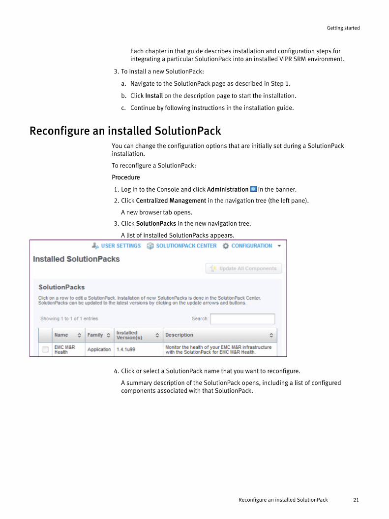
3. Click SolutionPacks in the new navigation tree.
A list of installed SolutionPacks appears.
4. Click or select a SolutionPack name that you want to reconfigure.
A summary description of the SolutionPack opens, including a list of configuredcomponents associated with that SolutionPack.
Getting started
Reconfigure an installed SolutionPack 21
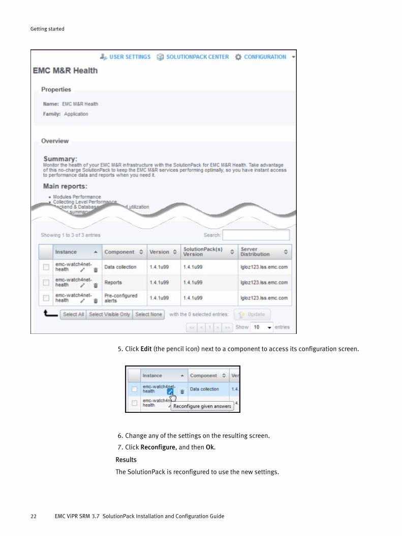
5. Click Edit (the pencil icon) next to a component to access its configuration screen.
6. Change any of the settings on the resulting screen.
7. Click Reconfigure, and then Ok.
Results
The SolutionPack is reconfigured to use the new settings.
Getting started
22 EMC ViPR SRM 3.7 SolutionPack Installation and Configuration Guide
Update SolutionPacksYou can configure ViPR SRM to automatically download updates and enhancements toSolutionPacks.
The Online Update feature helps you to quickly take advantage of new capabilities asthey are provided in each SolutionPack. You can configure, enable, and disableautomatic downloads of SolutionPack updates. You can also see currently availabledownloads and download history.
To access the Online Update feature:
Procedure
1. Log in to the Console, and click Administration in the banner.
2. Click Centralized Management in the navigation tree (the left pane).
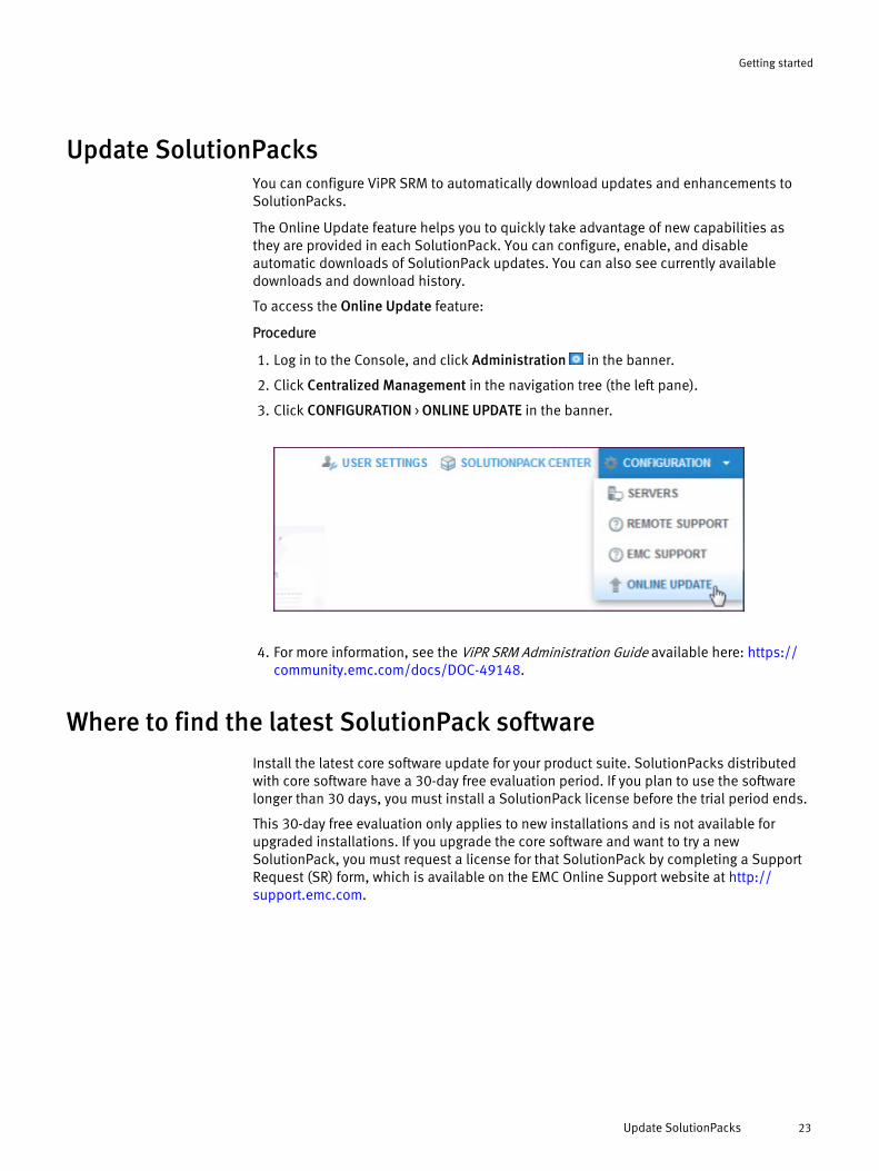
3. Click CONFIGURATION > ONLINE UPDATE in the banner.
4. For more information, see the ViPR SRM Administration Guide available here: https://community.emc.com/docs/DOC-49148.
Where to find the latest SolutionPack softwareInstall the latest core software update for your product suite. SolutionPacks distributedwith core software have a 30-day free evaluation period. If you plan to use the softwarelonger than 30 days, you must install a SolutionPack license before the trial period ends.
This 30-day free evaluation only applies to new installations and is not available forupgraded installations. If you upgrade the core software and want to try a newSolutionPack, you must request a license for that SolutionPack by completing a SupportRequest (SR) form, which is available on the EMC Online Support website at http://support.emc.com.
Getting started
Update SolutionPacks 23
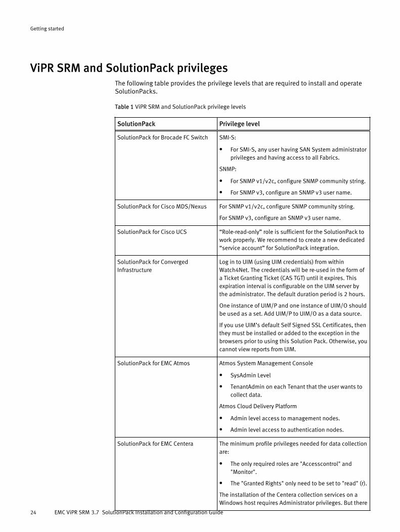
ViPR SRM and SolutionPack privilegesThe following table provides the privilege levels that are required to install and operateSolutionPacks.
Table 1 ViPR SRM and SolutionPack privilege levels
SolutionPack Privilege level
SolutionPack for Brocade FC Switch SMI-S:
l For SMI-S, any user having SAN System administratorprivileges and having access to all Fabrics.
SNMP:
l For SNMP v1/v2c, configure SNMP community string.
l For SNMP v3, configure an SNMP v3 user name.
SolutionPack for Cisco MDS/Nexus For SNMP v1/v2c, configure SNMP community string.
For SNMP v3, configure an SNMP v3 user name.
SolutionPack for Cisco UCS “Role-read-only” role is sufficient for the SolutionPack towork properly. We recommend to create a new dedicated“service account” for SolutionPack integration.
SolutionPack for ConvergedInfrastructure
Log in to UIM (using UIM credentials) from withinWatch4Net. The credentials will be re-used in the form ofa Ticket Granting Ticket (CAS TGT) until it expires. Thisexpiration interval is configurable on the UIM server bythe administrator. The default duration period is 2 hours.
One instance of UIM/P and one instance of UIM/O shouldbe used as a set. Add UIM/P to UIM/O as a data source.
If you use UIM’s default Self Signed SSL Certificates, thenthey must be installed or added to the exception in thebrowsers prior to using this Solution Pack. Otherwise, youcannot view reports from UIM.
SolutionPack for EMC Atmos Atmos System Management Console
l SysAdmin Level
l TenantAdmin on each Tenant that the user wants tocollect data.
Atmos Cloud Delivery Platform
l Admin level access to management nodes.
l Admin level access to authentication nodes.
SolutionPack for EMC Centera The minimum profile privileges needed for data collectionare:
l The only required roles are "Accesscontrol" and"Monitor".
l The "Granted Rights" only need to be set to "read" (r).
The installation of the Centera collection services on aWindows host requires Administrator privileges. But there
Getting started
24 EMC ViPR SRM 3.7 SolutionPack Installation and Configuration Guide

Table 1 ViPR SRM and SolutionPack privilege levels (continued)
SolutionPack Privilege level
is a workaround described in KnowledgeBase article188584 that will allow the post-install running of theseservices as a non-Administrator user.
SolutionPack for EMC Data Domain No user authentication required. ViPR SRM will extract thedata using SNMP "V2C" with the community string as"Public."
SolutionPack for EMC Data ProtectionAdvisor
DPA user needs a custom role with Manage ScheduledReports privileges enabled on DPA server.Enabling the Manage Scheduled Reports will also enableRun reports and View existing scheduled reports andschedules. These privileges are sufficient for the DPASolutionPack to pull data from DPA server.
SolutionPack for EMC Host Interface Privileges are controlled by the configuration of the hostagent. No special privileges are required for a host to bediscovered.
SolutionPack for EMC Isilon Collection will work with root/admin users who haveadministrative privileges. Collection also works for a non-admin user that is a member of the AuditAdmin role. Thisrole has mostly READ ONLY privileges.
SolutionPack for EMC RecoverPoint l monitor account - read-only privileges
l admin account - has all privileges except security andweb-download
SolutionPack for EMC VMAX For ViPR SRM to collect all masking views whenSymmetrix Access Control (symacl) is enabled, theSolutions Enabler host must be added to an AccessGroup which has Access Type "BASE" and "VLOGIX" to alldevices.
For ViPR SRM to collect all masking views whenSymmetrix Authorization (symauth) is enabled the userperforming the collection only needs the Monitor role.
IMPORTANT: symauth "Monitor" role only works toretrieve all masking views with latest Solutions Enabler7.6.2.25 (hotfix 1843/service alert 1708). Older versionsof Solutions Enabler 7.6.2 (ex. 7.6.2.8 which wasrequired in ViPR SRM 3.5 release) required "StorageAdmin" or "Admin" role in order to retrieve all maskingviews.
Windows-based collector host running VMAX SolutionPack and using "remote" SYMAPI Server:
l The Windows "System" account runs the Collectorservice which performs the VMAX collection
l The Windows "System" account therefore executesthe SYMCLI commands to get the masking view.
l In order for symauth to retrieve all masking views thecollector hosts's "System" user account must at least
Getting started
ViPR SRM and SolutionPack privileges 25

Table 1 ViPR SRM and SolutionPack privilege levels (continued)
SolutionPack Privilege level
have the "Monitor" role authorized. Again, thisassumes Solutions Enabler 7.6.2.25 or higher isinstalled
l Otherwise if an older 7.6.2 Solutions Enabler isinstalled then "Storage Admin" or "Admin" role wouldbe required.
Linux-based collector host running VMAX SolutionPack:
l The "apg" user account runs the Collector servicewhich performs the VMAX collection
l The "apg" user therefore executes the SYMCLIcommands to get the masking views
l In order for symauth to retrieve all masking views theSRM ViPR Linux collector hosts's "apg" user accountmust at least have the "Monitor" role authorized.Again, this assumes Solutions Enabler 7.6.2.25 orhigher is installed
l Otherwise, if an older 7.6.2 Solutions Enabler isinstalled, then "Storage Admin" or "Admin" rolewould be required.
SolutionPack for EMC VNX VNX Block -- User with Operator role or higher. NOTE: Ifthe user only has the Operator role and you run the status"Test" from Discovery Center, the "statistics logging" testwill always fail. To confirm Statistics Logging is enabled,you should login to Unisphere as a user withAdministrator privileges. Once Statistics Logging isenabled, the Operartor user will be able to collectperformance data from the array.
VNX File -- A local user for file with Operator role or higher.The "CLI access allowed" check box must be checked.
SolutionPack for EMC ViPR Controller Set the following roles in the Virtual Data Center
l System Monitor - Retrieves metering and monitoringrecords for the Virtual Data Center.
l System Auditor - Retrieves audit logs for the VirtualData Center.
SolutionPack for EMC VPLEX Use the management CLI and the Linux shell account tonavigate on the management station. The service accountthat is used by default is both a Linux account and a CLIaccount.
From the perspective of the management CLI, the serviceuser is not read-only, because you can perform someprovisioning operations on the VPLEX, although it doesnot have full administrative capabilities.
Getting started
26 EMC ViPR SRM 3.7 SolutionPack Installation and Configuration Guide

Table 1 ViPR SRM and SolutionPack privilege levels (continued)
SolutionPack Privilege level
From the perspective of the Linux shell, the serviceaccount is a regular user account so you cannot dooperations that require root privilege.
For a non-service account, follow these additional stepsonce the user has been created. This is assuming theSolutionPack is already installed using the serviceaccount. If it is being installed for the first time with anon-service user, you do not need this procedure.
1. Change the permission to the virt-volumes folder withfollowing command: chmod g+w virt-volumes // run under /var/log/Vplex/cli/w4
2. Reconfigure the VPLEX SolutionPack with thealternate account
SolutionPack for EMC XtremIO Non-admin account with read-only privileges.
SolutionPack for Hitachi DeviceManager
Non-privileged account with rights to view all.
SolutionPack for HP 3PAR StoreServ Non-privileged account with rights to view all.
SolutionPack for HP EVA Admin rights are required.
SolutionPack for HP StorageWorksP9000
Non-privileged account with rights to view all.
SolutionPack for IBM DS Non-admin account with read-only privileges.
Discover DS8000 devices with Monitor privileges.
SolutionPack for IBM LPAR HMC credentials
l User role or Operator (recommended), or HMC Viewer(minimum).
l Refer to table 4 at http://www-01.ibm.com/support/knowledgecenter/POWER6/ipha1/hmctasksanduserroles.htm
SolutionPack for IBM SAN VolumeController/Storwize
All the performance, topology and capacity metrics aresupported for a user who is a member of the"Administrator" user group. Performance data such asCPU usage, Port traffic statistics of non-configurationnodes are not supported for a user who is not a memberof the "Administrator" user group.
SolutionPack for IBM XIV Discovery works with Read Only, Storage Administrator,Application Administrator access.
Read Only is the minimum required.
Getting started
ViPR SRM and SolutionPack privileges 27

Table 1 ViPR SRM and SolutionPack privilege levels (continued)
SolutionPack Privilege level
Note
Due to limitations with the IBM software, discovery usingthe LDAP users will not happen if there is no active IBMXIV GUI user session, either by the corresponding LDAPuser or a stroage administrator.
SolutionPack for Microsoft Hyper-V Admin rights are required in order to run unsignedPowerShell scripts.In order to do this, you must run the following commandas an administrative user:
PowerShell -C Set-ExecutionPolicyUnrestrictedOn Microsoft Windows Server 2008 R2 and MicrosoftWindows Server 2012 Hyper-V hosts, the domainadministrative user must use be member of domaingroup Domain Admins. In other words, is not enough tomake a domain user member of local groupAdministrators in Hyper-V hosts.
On Microsoft Windows Server 2008 R2 and MicrosoftWindows Server 2012 Hyper-V hosts, the WMI queries canbe performed only using the build-in Administrator localuser. Any other local administrative local user will beunable to perform the queries because the UAC controls.
On Microsoft Hyper-V Server 2012 and Microsoft WindowsServer 2012 Hyper-V hosts, is possible to collect datausing a non-administrative local or domain user. Thisuser must be member of local groups Hyper-VAdministrators and Performance Log Users groups.Unfortunately, this will not possible in Microsoft Hyper-VServer 2008 R2 and Microsoft Windows Server 2008 R2.
SolutionPack for Microsoft SQL Server l SQL authentication requires that the user be amember of the SYSADMIN group
l Windows user account requires the user be amember of the Guests group or the Domain Guestsgroup
l The default database must be the master
l Windows user account must be imported into theMicrosoft SQL Server with settings similar to these:
n Server roles of public
n Securable grants for Connect SQL, View anydefinitions, and View server state
SolutionPack for NetApp Filer SSH connection to the 7-Mode NetApp devices with thefollowing role:
Getting started
28 EMC ViPR SRM 3.7 SolutionPack Installation and Configuration Guide

Table 1 ViPR SRM and SolutionPack privilege levels (continued)
SolutionPack Privilege level
l login-ssh, cli-stats*, cli-snap*, cli-aggr*, cli-vol*, cli-disk*, cli-nfs*, cli-cifs*, cli-df, cli-sysconfig, cli-ifconfig, cli-qtree, cli-quota, cli-storage, cli-maxfiles,cli-echo, cli-lun, cli-fcp, cli-vfiler, cli-exportfs
SSH connection to the C-Mode NetApp devices with thefollowing role:
l Access level 'readonly' for the commands : volume,df, lun, storage, statistics, network, vserver, cluster,sleep, snapmirror
l Access level 'all' for the commands: set, system
SolutionPack for Oracle Database The Watch4net collector must connect to each instance ofOracle databases and perform SQL queries. You can useeither an administrator equivalent system account, orcreate a dedicated system account for the collector. If youwant to use the last option, ask the DBA administrator torun the query described in the SolutionPack for Oraclechapter.
This will create a "watch4net" account, which specificgrant for the Watch4net collector.
SolutionPack for Oracle MySQLDatabase
This SolutionPack requires MySQL database user loginprivileges to collect information from MySQL databaseservers running remotely.
SolutionPack for Physical Hosts Windows user privileges
l Domain user in the local administrator's group(recommended), or
l Local administrator for the host.
UNIX user privileges
l Sudo user with read/execute permissions forcommands, or
l SSH public/private key pair with execute permissionfor commands.
Refer to the SolutionPack for Physical Hosts chapter formore information.
VIO server
l SUDO user role with elevated (root) privileges toexecute commands to be run on the VIOS host.
l Note: The padmin role is not required for VIO Servers.
VIO Client/LPAR
l SUDO user role (or)
l SSH Keys (or)
l root user (optional)
Getting started
ViPR SRM and SolutionPack privileges 29

Table 1 ViPR SRM and SolutionPack privilege levels (continued)
SolutionPack Privilege level
SolutionPack for VI VirtualWisdom Windows Administrator privileges are required to installthe VI proxy software.
SolutionPack for VMware vCenter Discovery works with read-only non-admin user.
Getting started
30 EMC ViPR SRM 3.7 SolutionPack Installation and Configuration Guide

CHAPTER 2
SolutionPack for Block Chargeback
l Overview............................................................................................................... 32l Chargeable and non-chargeable metrics ...............................................................32l Installing the SolutionPack....................................................................................33l Running the chargeback preprocessor task manually............................................ 35l Enable collecting component level metrics for a limited set of hosts......................36l Limitations ........................................................................................................... 36
SolutionPack for Block Chargeback 31

OverviewThe SolutionPack for Block Chargeback provides visibility into block storage usage andassociated costs by host or by defined groups of hosts in your environment.
When you install the SolutionPack, it creates a chargeback preprocessor task that runs asconfigured during SolutionPack installation and collects block chargeback metrics for allphysical hosts and virtual machines. Primary Used, Primary Presented, Total Used, andTotal Presented are the four use cases. The reports display chargeable capacities andcost for every physical host, virtual machine, hypervisor cluster and defined device groupfor each of these use cases. The reports also display chargeable capacity by service level.
The block chargeback reports are available under Reports Library > Chargeback and alsounder Explore > Storage > More Reports > Chargeback by Host and Dashboards > Storage >Chargeback by Group.
Main reports
Chargeback by Host > Chargeback by Host/Hypervisors
Shows the Primary Used Chargeable, Primary Presented Chargeable, Total UsedChargeable, and Total Presented Chargeable capacities and costs for each host orhypervisor.
Chargeback by Host > Chargeback by Virtual Machines
Shows the Primary Used Chargeable, Primary Presented Chargeable, Total UsedChargeable, and Total Presented Chargeable capacities and costs for each virtualmachine.
Chargeback by Host > Chargeback by Hypervisor Cluster
Shows the Primary Used Chargeable, Primary Presented Chargeable, Total UsedChargeable, and Total Presented Chargeable capacities and costs for all hypervisorclusters.
Chargeback by Group
Shows the Primary Used Chargeable, Primary Presented Chargeable, Total UsedChargeable, and Total Presented Chargeable capacities and costs for groups ofhosts.
Chargeable and non-chargeable metricsThis SolutionPack can generate both chargeable and non-chargeable metrics. Non-chargeable metrics are optional, and are disabled by default during SolutionPackinstallation.
If storage is not shared across hosts, there is no difference in chargeable and non-chargeable metric values.
The values are different when multiple hosts share a storage disk.
l Non-chargeable metrics are the values as seen directly by the host. The same valuesare duplicated for each of the hosts sharing that storage, without regard for howmany hosts are sharing it.
l Chargeable metrics take host sharing into account, and divide the metrics by thenumber of hosts that are sharing it. The metrics are deduplicated, making themrepresentative of chargeability.
SolutionPack for Block Chargeback
32 EMC ViPR SRM 3.7 SolutionPack Installation and Configuration Guide

ExamplesIf two hosts are sharing 500GB of block storage from the same disk, and none of thatstorage is used, the capacity metrics are as shown in the following table.
Table 2 Shared disk with no storage used
Metric name Host A - Disk1 Host B - Disk1
Non-Chargeable Presented(= total capacity of the disk)
500GB 500GB
Non-Chargeable Used( = used capacity of the disk)
0 0
Chargeable Presented( = total capacity of the disk ÷ # hosts sharing it)
250GB 250GB
Chargeable Used(= used capacity of the disk ÷ # hosts sharing it)
0 0
Alternatively, if Host A uses 100GB of this storage, the capacity metrics are as follows.
Table 3 Shared disk with some storage used
Metric name Host A - Disk1 Host B - Disk1
Non-Chargeable Presented(= total capacity of the disk)
500GB 500GB
Non-Chargeable Used(this has changed from 0 to 100 GB)
100GB 100GB
Chargeable Presented( = total capacity of the disk ÷ # hosts sharing it)
250GB 250GB
Chargeable Used(= used capacity of the disk ÷ # hosts sharing it)
50GB 50GB
Installing the SolutionPackBefore you beginl Identify the collector host to use for the chargeback preprocessor.l Identify the chargeback use case that you are interested in. Possible options are:
n Presented—Only presented capacity and cost metrics are computed. Presentedcapacity is based on the total capacity provisioned to the host but not necessarilywritten.
n Used—Only used capacity and cost metrics are computed. Used capacity is basedon the actual capacity written by the host.
n Both (Default)—Both used and presented capacity and cost metrics are computed.l Identify whether or not non-chargeable capacity and cost metrics are needed. If the
Enable non-chargeable metrics option is enabled, non-chargeable metrics arecreated in addition to the chargeable metrics. Non-chargeable metrics are key-performance indicators of storage, showing the capacities and costs for the storagebefore deduplication is applied for the hosts sharing that storage.
SolutionPack for Block Chargeback
Installing the SolutionPack 33
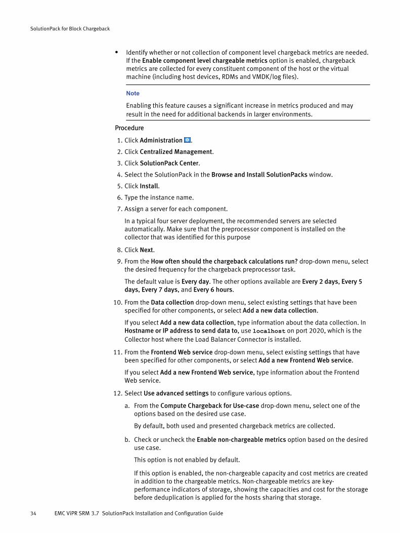
l Identify whether or not collection of component level chargeback metrics are needed.If the Enable component level chargeable metrics option is enabled, chargebackmetrics are collected for every constituent component of the host or the virtualmachine (including host devices, RDMs and VMDK/log files).
Note
Enabling this feature causes a significant increase in metrics produced and mayresult in the need for additional backends in larger environments.
Procedure
1. Click Administration .
2. Click Centralized Management.
3. Click SolutionPack Center.
4. Select the SolutionPack in the Browse and Install SolutionPacks window.
5. Click Install.
6. Type the instance name.
7. Assign a server for each component.
In a typical four server deployment, the recommended servers are selectedautomatically. Make sure that the preprocessor component is installed on thecollector that was identified for this purpose
8. Click Next.
9. From the How often should the chargeback calculations run? drop-down menu, selectthe desired frequency for the chargeback preprocessor task.
The default value is Every day. The other options available are Every 2 days, Every 5days, Every 7 days, and Every 6 hours.
10. From the Data collection drop-down menu, select existing settings that have beenspecified for other components, or select Add a new data collection.
If you select Add a new data collection, type information about the data collection. InHostname or IP address to send data to, use localhost on port 2020, which is theCollector host where the Load Balancer Connector is installed.
11. From the Frontend Web service drop-down menu, select existing settings that havebeen specified for other components, or select Add a new Frontend Web service.
If you select Add a new Frontend Web service, type information about the FrontendWeb service.
12. Select Use advanced settings to configure various options.
a. From the Compute Chargeback for Use-case drop-down menu, select one of theoptions based on the desired use case.
By default, both used and presented chargeback metrics are collected.
b. Check or uncheck the Enable non-chargeable metrics option based on the desireduse case.
This option is not enabled by default.
If this option is enabled, the non-chargeable capacity and cost metrics are createdin addition to the chargeable metrics. Non-chargeable metrics are key-performance indicators of storage, showing the capacities and cost for the storagebefore deduplication is applied for the hosts sharing that storage.
SolutionPack for Block Chargeback
34 EMC ViPR SRM 3.7 SolutionPack Installation and Configuration Guide

c. Check or uncheck the Enable component level chargeable metrics option basedon what was identified earlier.
This option is not enabled by default.
If this option is enabled, chargeback metrics are collected for every constituentcomponent of the host or the virtual machine (including host devices, RDMs, andVMDK/log files).
Note
Enabling this feature causes a significant increase in metrics produced and mayresult in the need for additional backends in larger environments.
13. Click Next.
The window displays reports settings.
14. Click Install.
15. Click OK when the installation is complete.
After you finish
Chargeback reports are available under Reports Library > Chargeback and also underExplore > Storage > More Reports > Chargeback by Host and Dashboards > Storage >Chargeback by Group.
The reports are empty immediately after the SolutionPack is installed. They startdisplaying data only after the chargeback preprocessor task completes successfully anddata has had sufficient time to propagate through the environment. This task runs usingthe schedule selected during installation.
Chargeback data is affected by user configuration changes in Centralized Management >Groups Management, such as changes to service level tags and user-defined groupdefinitions. In general, expect to wait one day plus the frequency of the chargeback taskto see reconfigured chargeback data after such changes.
To shorten these wait times, wait for data collection to occur and then manually run thechargeback preprocessor task. For example, if the chargeback preprocessor task isscheduled to run every 5 days, wait the one day for data to settle and then manually runthe task.
Running the chargeback preprocessor task manuallyYou can run the chargeback preprocessor task manually rather than waiting for thescheduled run
Procedure
1. Go to Administration > Centralized Management > Scheduled Tasks.
2. Expand the Chargeback node.
3. Select the chargeback processor instance. The default instance name ischargeback-processor-generic-chargeback.
4. In the right pane, click Run Now.
SolutionPack for Block Chargeback
Running the chargeback preprocessor task manually 35

Enable collecting component level metrics for a limited set ofhosts
You can specify a list of hosts to the collector to limit collection.
Use this procedure to enable full collection of certain hosts regardless of SolutionPackconfiguration settings.
Procedure
1. Go to Administration > Logical Overview > Miscellaneous > Tools > ChargebackProcessor::Generic Chargeback.
2. In the right pane, click the arrow on the Configuration files row to expand it.
3. Select the file named /conf/chargeback-processor.properties, and clickEdit.
4. In the editing window, add the following entry to the end of the file:
cbp.usecase.whitelist=<hosts>
where <hosts> is a comma-separated list of hostnames.
5. If the whitelist separator must be changed to a character other than comma, add thefollowing additional entry:
cbp.usecase.whitelist.separator=separator
where separator is the character. For example, to use the pipe character as separator,enter:
cbp.usecase.whitelist.separator=|
Here are example entries:
#cbp.usecase.whitelist=host1,host2,host3#cpb.usecase.whitelist.separator=,
6. Click Save.
Note
Direct modifications to this file are lost if the SolutionPack is reconfigured. In thatcase, the modifications must be reentered.
Limitationsl When you upgrade from a previous version to ViPR SRM 3.7, the SolutionPack for
Block Chargeback is not installed by default and the old chargeback reports referencea broken link. You need to install the SolutionPack for Block Chargeback to obtainchargeback reports and resolve this link.
SolutionPack for Block Chargeback
36 EMC ViPR SRM 3.7 SolutionPack Installation and Configuration Guide

l Hosts that are not completely discovered and hosts with only local disks do not showup in chargeback reports.
l Delegation of chargeable capacities to host disk capacity when the backend array isnot discovered is not supported for passive hosts nor for Windows hosts discoveredthrough the SolutionPack for Physical Hosts using a user with non-admin privileges.
l This SolutionPack does not support chargeback reporting for:
n Microsoft Hyper-V
n Virtual Machines where the datastore on which the VM resides is backed by BOTHa LUN and a virtual volume
n Virtual Machines where the datastore on which the VM resides is backed by BOTHa local virtual volume and a remote virtual volume
n Virtual volumes backed by RAID 1 (mirrored) LUNs
n Hosts with disks that are backed by a distributed virtual volume if any of thearrays contributing to the storage of that distributed virtual volume areundiscovered
l If two or more VMs have the same display name, but different host names and IPaddresses, their chargeback capacities get grouped under one VM.
SolutionPack for Block Chargeback
Limitations 37

SolutionPack for Block Chargeback
38 EMC ViPR SRM 3.7 SolutionPack Installation and Configuration Guide

CHAPTER 3
SolutionPack for Brocade FC Switch
l Overview............................................................................................................... 40l Brocade switch and SMI agent configuration......................................................... 41l Installing the SolutionPack....................................................................................42l Passive host discovery configuration options........................................................ 45
SolutionPack for Brocade FC Switch 39

OverviewThe SolutionPack for Brocade FC Switch accesses performance data information that wasautomatically collected and interpreted (using resource grouping and mathematicalcalculations) from across multiple fabrics. Alerts are consolidated from Brocade FCSwitches and shown on the All Alerts Console
Data collection methods
Note
Choose one of the options below. Do not use both options simultaneously.
SMI-S Only
Discover switch topology, performance and zoning details through SMI-S.
SNMP + SMI-S (Zoning only through SMI-S)
Discover switch topology and performance metrics through SNMP. SNMP does notsupport zoning discovery. Restrict SMI-S discovery to zoning details only.
Main reports
FC Switches Summary
Overviews the FC switches, including key indicators such as name, IP addresses,firmware version, and operational status.
# FC Ports with Errors
Reports the FC ports with errors, such as invalid CRCs, signal losses, or link failures.
Fabrics Overall Health
Reports the current operational status of the switch.
Inventory & Performance
Reports Inter-Switch-Link (ISL) trunking resource usage. ISL monitoring helpsadministrators determine the sources of traffic on ISLs and identify potential pointsof congestion in the SAN fabric.
Throughput by Switches (/s)
Reports the Throughput by switches. Typically, this is the sum of throughput for allFC ports belonging to a switch.
Throughput by Port Type (/s)
Reports the Throughput by port type. Typically, this is the sum of throughput of all FCports of each port type on the switches.
Traffic by Domains (/s)
Reports the Throughput by domains. Typically, this is the sum of throughput of all FCPorts grouped by Domain ID of switches.
Situation To Watch
Highlights risk situations such as FC ports errors.
Virtual Fabrics
Reports the virtual Fabrics configured on all switches available in the environment
SolutionPack for Brocade FC Switch
40 EMC ViPR SRM 3.7 SolutionPack Installation and Configuration Guide

Recommendations on using SolutionPack for Brocade FC SwitchThe recommended discovery approach is to use SMI-S only data collection (in both freshdeployment of ViPR SRM and upgrade from previous versions).SNMP + SMI-S (Zoning only through SMI-S) data collection is supported for backwardcompatibility with previous versions and will be deprecated in a future release.
Supported collection interfacesFor information about supported collection interfaces, refer to the ViPR SRM SupportMatrix.
Brocade switch and SMI agent configurationYou must configure Brocade switches and SMI agents for discovery and alertconsolidation in ViPR SRM.
l Configuring Brocade SMI Agents on page 41
l Configuring Brocade switches for alert consolidation on page 41
l Configuring Brocade Switches for SNMP discovery on page 42
Configuring Brocade SMI AgentsInstall and configure Brocade SMI agent for complete switch discovery (if you chooseSMI-S Only discovery option) or zoning discovery only (if you choose the SNMP+SMI-Sdiscovery option).
Procedure
1. Install Brocade SMI agent in one of the following modes:
Installation mode Description
Integrated Brocade SMIAgent
The Brocade SMI agent is integrated with CMCNE, BNA,CMDCE, DCFM and gets installed when you install anyof these products.
Brocade SMI Agent only(headless installation)
Headless installation (silent mode installation) doesnot need a license and installs the SMI agent only.
Refer to the CMCNE/CMDCE installation guide for more details on installation andconfiguration of Brocade SMI agent.
Configuring Brocade switches for alert consolidationUse the snmpConfig command to forward SNMP v1 traps from Brocade switches toViPR SRM.
Trap-based alerts for Brocade switches are supported through SNMP regardless of thediscovery option you choose. In other words, even if you choose the SMI-S Only discoveryapproach, configure the switches for SNMP trap forwarding.
Use the snmpConfig command to forward SNMP v1 traps from Brocade switches to ViPRSRM.
Procedure
1. Log into the Brocade FC switch as the administrator.
2. Type snmpConfig ––set snmpv1 , and press Enter.
SolutionPack for Brocade FC Switch
Brocade switch and SMI agent configuration 41

3. Type the following details, when prompted:
Option Input
Community [public]
Trap recipient's IPaddress
The ViPR SRM trap recipient IP which, in a single vAppinstallation is the ViPR SRM IP, and in a distributedenvironment, is the Backend server's IP.
Trap recipient severitylevel
(0..5)
Trap recipient port 2041, which is the ViPR SRM trap listening port.
4. If you have multiple Brocade FC switches in your storage environment, repeat thisprocedure on each switch.
Configuring Brocade switches for SNMP discovery
Brocade switches have to be configured with SNMP v1/v2c/v3 credentials if you chooseSNMP+SMI-S (zoning only through SMI-S) discovery option.
Procedure
1. Launch a command line interface for the Brocade switch and log in with Administratorcredentials.
2. Perform the following steps to configure the switch for SNMPv1/v2c:
a. Type snmpConfig --show snmpv1The community strings will be listed.
b. If you wish to change a community string, type snmpConfig --set snmpv1c. Enter the new community string and proceed.
3. Perform the following steps to configure the switch for SNMPv3:
a. Type snmpConfig --show snmpv3.
The configuration parameters will be listed.
b. If you wish to change the parameters, type snmpConfig --set snmpv3c. Enter the parameters and proceed.
4. Repeat these steps for each Brocade switch in your storage environment.
Installing the SolutionPack
Before you begin
l To discover the switch topology (switch details and switch port details) and switchperformance using SNMP and zoning details through SMIS, you must be aware ofSNMP v1/v2 community strings and SNMP ports, or SNMP v3 user details and privacyand authentication details for the v3 username. In addition, the username, password,port number, and SSL enabled/status for the SMI-S provider are required to discoverthe zoning details
SolutionPack for Brocade FC Switch
42 EMC ViPR SRM 3.7 SolutionPack Installation and Configuration Guide

l To discover the switch topology, switch performance, and zoning details throughSMIS, the username, password, port number, and SSL enabled/status for the SMI-Sprovider are required
l The ViPR SRM Alerting Guide explains how to configure alerts consolidation.
l The Topology Mapping files that push the switch details to the topology store residesin the Generic-SNMP block. The Generic-SNMP block should be present on theBrocade collector to push the switch data to the topology store.
Procedure
1. Click Administration .
2. Click Centralized Management.
3. Click SolutionPack Center.
4. Select the SolutionPack in the Browse and Install SolutionPacks window.
5. Click Install.
6. Type the instance name.
7. Assign a server for each component.
In a typical four server deployment, the recommended servers are selectedautomatically.
8. Click Next.
The window displays a note about Alert Consolidation.
9. Click Next.
The window displays pre-configured alert details.
10. From the Alerting on data collection drop-down menu, select existing settings thathave been specified for other components, or select Add a new alerting datacollection.
If you select Add a new alerting on data collection, choose an alerting web-serviceinstance.
11. Click Next.
The window displays SMI data collection details.
12. From the Data collection drop-down menu, select existing settings that have beenspecified for other components, or select Add a new data collection.
If you select Add a new data collection, type information about the data collection. InHostname or IP address to send data to, use localhost on port 2020, which is theCollector host where the Load Balancer Connector is installed.
13. Leave Enable Topology Backend on data collected checked.
14. From the Topology Service drop-down menu, select existing settings that have beenspecified for other components, or select Add a new Topology Service.
If you select Add a new Topology service, provide information about the topologyservice and the web service. In Topology Service hostname or IP address, specify thePrimary Backend.
From the Web-Service Gateway drop-down menu, select existing settings that havebeen specified for other components, or select Add new gateway. If you select Addnew gateway, provide information about the web-service gateway where the topologyservice resides.
SolutionPack for Brocade FC Switch
Installing the SolutionPack 43
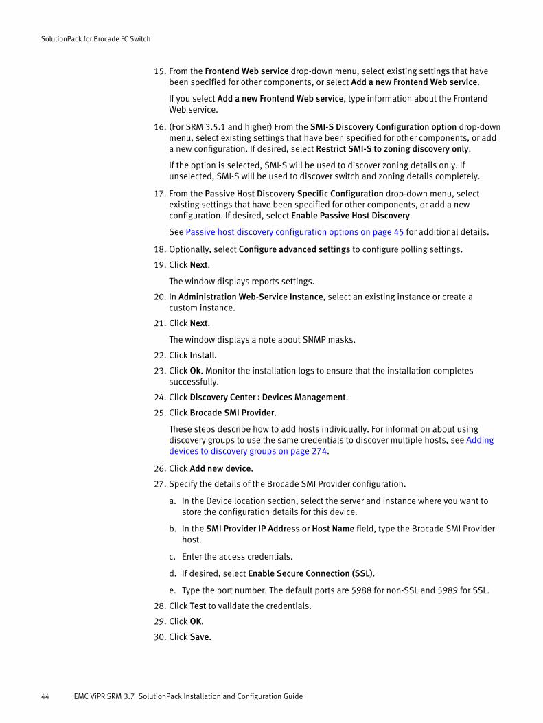
15. From the Frontend Web service drop-down menu, select existing settings that havebeen specified for other components, or select Add a new Frontend Web service.
If you select Add a new Frontend Web service, type information about the FrontendWeb service.
16. (For SRM 3.5.1 and higher) From the SMI-S Discovery Configuration option drop-downmenu, select existing settings that have been specified for other components, or adda new configuration. If desired, select Restrict SMI-S to zoning discovery only.
If the option is selected, SMI-S will be used to discover zoning details only. Ifunselected, SMI-S will be used to discover switch and zoning details completely.
17. From the Passive Host Discovery Specific Configuration drop-down menu, selectexisting settings that have been specified for other components, or add a newconfiguration. If desired, select Enable Passive Host Discovery.
See Passive host discovery configuration options on page 45 for additional details.
18. Optionally, select Configure advanced settings to configure polling settings.
19. Click Next.
The window displays reports settings.
20. In Administration Web-Service Instance, select an existing instance or create acustom instance.
21. Click Next.
The window displays a note about SNMP masks.
22. Click Install.
23. Click Ok. Monitor the installation logs to ensure that the installation completessuccessfully.
24. Click Discovery Center > Devices Management.
25. Click Brocade SMI Provider.
These steps describe how to add hosts individually. For information about usingdiscovery groups to use the same credentials to discover multiple hosts, see Addingdevices to discovery groups on page 274.
26. Click Add new device.
27. Specify the details of the Brocade SMI Provider configuration.
a. In the Device location section, select the server and instance where you want tostore the configuration details for this device.
b. In the SMI Provider IP Address or Host Name field, type the Brocade SMI Providerhost.
c. Enter the access credentials.
d. If desired, select Enable Secure Connection (SSL).
e. Type the port number. The default ports are 5988 for non-SSL and 5989 for SSL.
28. Click Test to validate the credentials.
29. Click OK.
30. Click Save.
SolutionPack for Brocade FC Switch
44 EMC ViPR SRM 3.7 SolutionPack Installation and Configuration Guide

Passive host discovery configuration optionsEnable passive host discovery to see end-to-end topology from hosts to arrays, andidentify chargeback on SAN enabled hosts without active host discovery.
You can passively resolve hosts, discovered through the SolutionPack for Brocade FCSwitch, from zoning records.The default zone naming patterns in ViPR SRM are:
z_%h%
z_%h%_*
z_%h%_*_*
%h%_*
After you have enabled passive host discovery, there are two options for passive hostconfiguration.
l Enable DNS Resolution: This option, which is enabled by default, resolves the "IP"property by using the DNS lookup handler. You can un-check this option to avoidusing the DNS lookup feature.
l Customize zone naming patterns: This option allows you to customize the zonenaming pattern. By default, this option is disabled, and ViPR SRM uses the fourdefault zone naming patterns. You can enable this option to add, delete, or modifythe default zone naming patterns and host name positions in zones.
You can enable passive host discovery while installing the SolutionPack, or you canenable it by reconfiguring the SMI Data Collection component of an existing instance ofthe SolutionPack.
To enable and add/edit customized zone naming patterns:
Procedure
1. Select the Enable Passive Host Discovery checkbox.
2. Select the Customized zone naming patterns checkbox.
The system displays the four default zone naming templates.
3. Click the Add button (plus icon) to view the zone naming pattern and host position fora template. Edit the pattern or position if desired.
Only Java-based zone naming patterns are supported.
Only plain numbers can be used for the position. Special characters (like $) are notrequired.
Table 4 Sample zone naming patterns
Regex is ^(z_)([A-Z0-9a-z]+)$and hostname position is 2
Matches all the zone names that start with 'z_' and extracts thehostname from the rest of the string that follows 'z_'Example: For zone name z_lingz099, the hostname extracted islingz099.
Regex is ^([^z_][A-Z0-9a-z]+)_([A-Za-z0-9]+) andhostname position is 1
Matches all the zone names that doesn't start with 'z_' andextracts the hostname from zone name that is before the firstunderscore.Example: For lgloe111_1106, the hostname extracted islgloe111.
SolutionPack for Brocade FC Switch
Passive host discovery configuration options 45

Table 4 Sample zone naming patterns (continued)
For more information on writing Java's regular expression refer to http://docs.oracle.com/javase/tutorial/essential/regex/
SolutionPack for Brocade FC Switch
46 EMC ViPR SRM 3.7 SolutionPack Installation and Configuration Guide
CHAPTER 4
SolutionPack for Cisco MDS
l Overview............................................................................................................... 48l Performing pre-configuration tasks........................................................................48l Configuring switches for SNMPv1 and SNMPv2c....................................................49l Configuring switches for SNMPv3.......................................................................... 50l Configuring Cisco switches for alert consolidation.................................................51l Installing the SolutionPack....................................................................................51l Enabling passive host discovery through Generic-SNMP........................................52l Enable and edit customized zone naming patterns................................................53l Limitations............................................................................................................53
SolutionPack for Cisco MDS 47
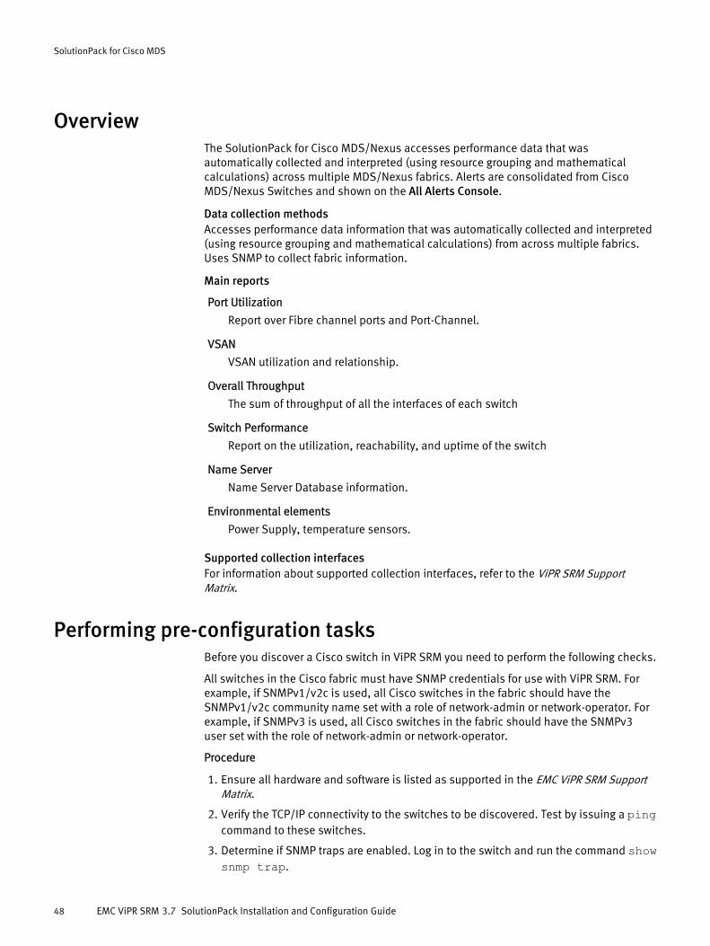
OverviewThe SolutionPack for Cisco MDS/Nexus accesses performance data that wasautomatically collected and interpreted (using resource grouping and mathematicalcalculations) across multiple MDS/Nexus fabrics. Alerts are consolidated from CiscoMDS/Nexus Switches and shown on the All Alerts Console.
Data collection methodsAccesses performance data information that was automatically collected and interpreted(using resource grouping and mathematical calculations) from across multiple fabrics.Uses SNMP to collect fabric information.
Main reports
Port Utilization
Report over Fibre channel ports and Port-Channel.
VSAN
VSAN utilization and relationship.
Overall Throughput
The sum of throughput of all the interfaces of each switch
Switch Performance
Report on the utilization, reachability, and uptime of the switch
Name Server
Name Server Database information.
Environmental elements
Power Supply, temperature sensors.
Supported collection interfacesFor information about supported collection interfaces, refer to the ViPR SRM SupportMatrix.
Performing pre-configuration tasksBefore you discover a Cisco switch in ViPR SRM you need to perform the following checks.
All switches in the Cisco fabric must have SNMP credentials for use with ViPR SRM. Forexample, if SNMPv1/v2c is used, all Cisco switches in the fabric should have theSNMPv1/v2c community name set with a role of network-admin or network-operator. Forexample, if SNMPv3 is used, all Cisco switches in the fabric should have the SNMPv3user set with the role of network-admin or network-operator.
Procedure
1. Ensure all hardware and software is listed as supported in the EMC ViPR SRM SupportMatrix.
2. Verify the TCP/IP connectivity to the switches to be discovered. Test by issuing a pingcommand to these switches.
3. Determine if SNMP traps are enabled. Log in to the switch and run the command showsnmp trap.
SolutionPack for Cisco MDS
48 EMC ViPR SRM 3.7 SolutionPack Installation and Configuration Guide
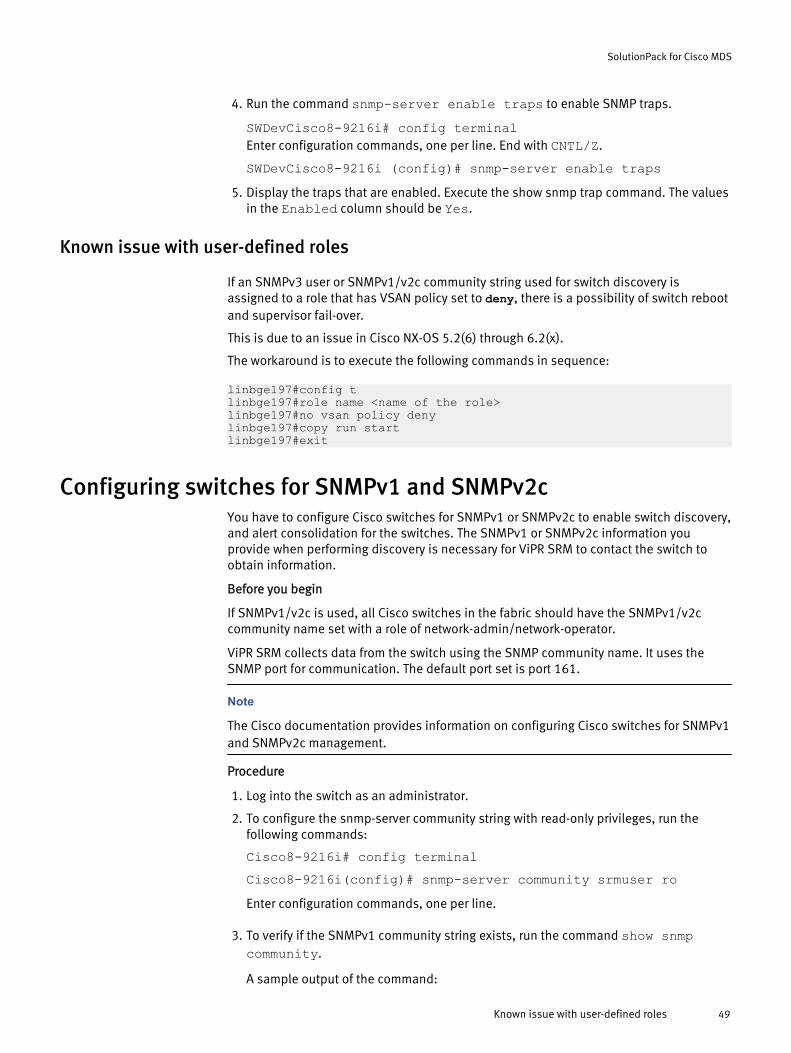
4. Run the command snmp-server enable traps to enable SNMP traps.
SWDevCisco8-9216i# config terminalEnter configuration commands, one per line. End with CNTL/Z.
SWDevCisco8-9216i (config)# snmp-server enable traps5. Display the traps that are enabled. Execute the show snmp trap command. The values
in the Enabled column should be Yes.
Known issue with user-defined roles
If an SNMPv3 user or SNMPv1/v2c community string used for switch discovery isassigned to a role that has VSAN policy set to deny, there is a possibility of switch rebootand supervisor fail-over.
This is due to an issue in Cisco NX-OS 5.2(6) through 6.2(x).
The workaround is to execute the following commands in sequence:
linbge197#config tlinbge197#role name <name of the role>linbge197#no vsan policy denylinbge197#copy run startlinbge197#exit
Configuring switches for SNMPv1 and SNMPv2cYou have to configure Cisco switches for SNMPv1 or SNMPv2c to enable switch discovery,and alert consolidation for the switches. The SNMPv1 or SNMPv2c information youprovide when performing discovery is necessary for ViPR SRM to contact the switch toobtain information.
Before you begin
If SNMPv1/v2c is used, all Cisco switches in the fabric should have the SNMPv1/v2ccommunity name set with a role of network-admin/network-operator.
ViPR SRM collects data from the switch using the SNMP community name. It uses theSNMP port for communication. The default port set is port 161.
Note
The Cisco documentation provides information on configuring Cisco switches for SNMPv1and SNMPv2c management.
Procedure
1. Log into the switch as an administrator.
2. To configure the snmp-server community string with read-only privileges, run thefollowing commands:
Cisco8-9216i# config terminalCisco8-9216i(config)# snmp-server community srmuser roEnter configuration commands, one per line.
3. To verify if the SNMPv1 community string exists, run the command show snmpcommunity.
A sample output of the command:
SolutionPack for Cisco MDS
Known issue with user-defined roles 49
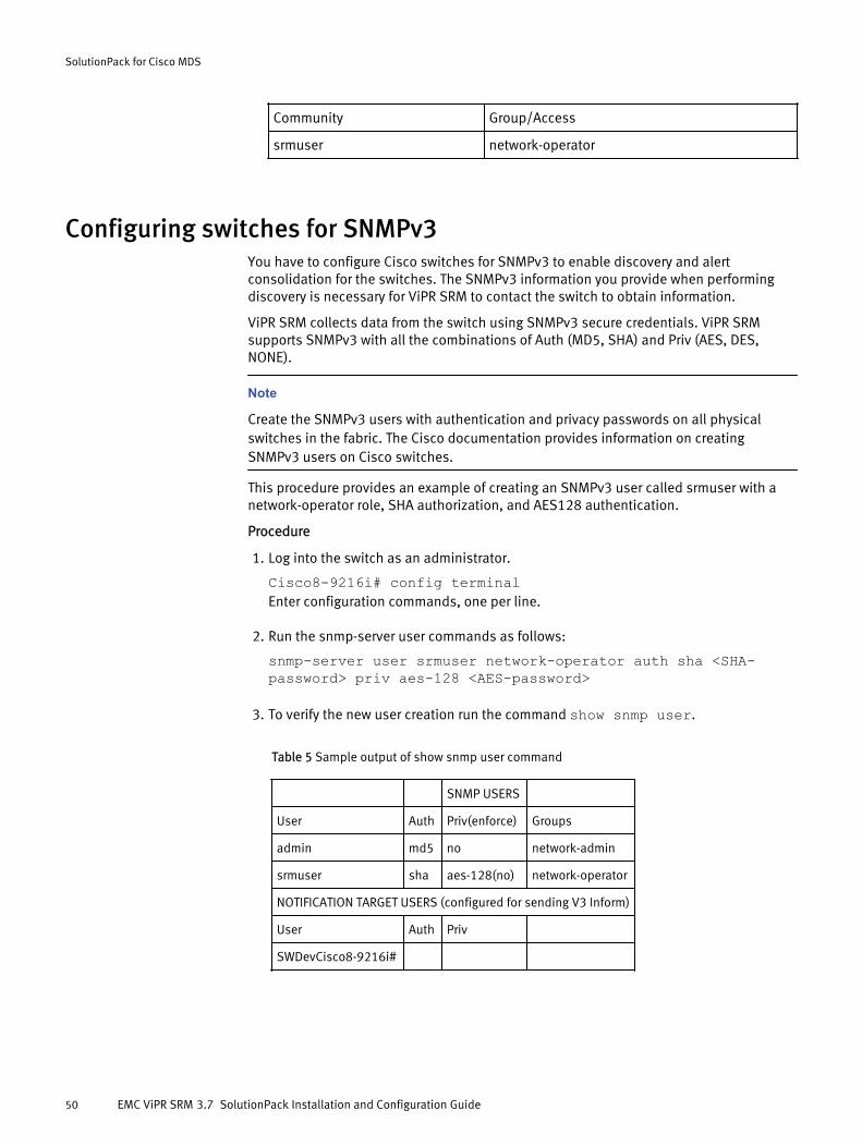
Community Group/Access
srmuser network-operator
Configuring switches for SNMPv3You have to configure Cisco switches for SNMPv3 to enable discovery and alertconsolidation for the switches. The SNMPv3 information you provide when performingdiscovery is necessary for ViPR SRM to contact the switch to obtain information.
ViPR SRM collects data from the switch using SNMPv3 secure credentials. ViPR SRMsupports SNMPv3 with all the combinations of Auth (MD5, SHA) and Priv (AES, DES,NONE).
Note
Create the SNMPv3 users with authentication and privacy passwords on all physicalswitches in the fabric. The Cisco documentation provides information on creatingSNMPv3 users on Cisco switches.
This procedure provides an example of creating an SNMPv3 user called srmuser with anetwork-operator role, SHA authorization, and AES128 authentication.
Procedure
1. Log into the switch as an administrator.
Cisco8-9216i# config terminalEnter configuration commands, one per line.
2. Run the snmp-server user commands as follows:
snmp-server user srmuser network-operator auth sha <SHA-password> priv aes-128 <AES-password>
3. To verify the new user creation run the command show snmp user.
Table 5 Sample output of show snmp user command
SNMP USERS
User Auth Priv(enforce) Groups
admin md5 no network-admin
srmuser sha aes-128(no) network-operator
NOTIFICATION TARGET USERS (configured for sending V3 Inform)
User Auth Priv
SWDevCisco8-9216i#
SolutionPack for Cisco MDS
50 EMC ViPR SRM 3.7 SolutionPack Installation and Configuration Guide
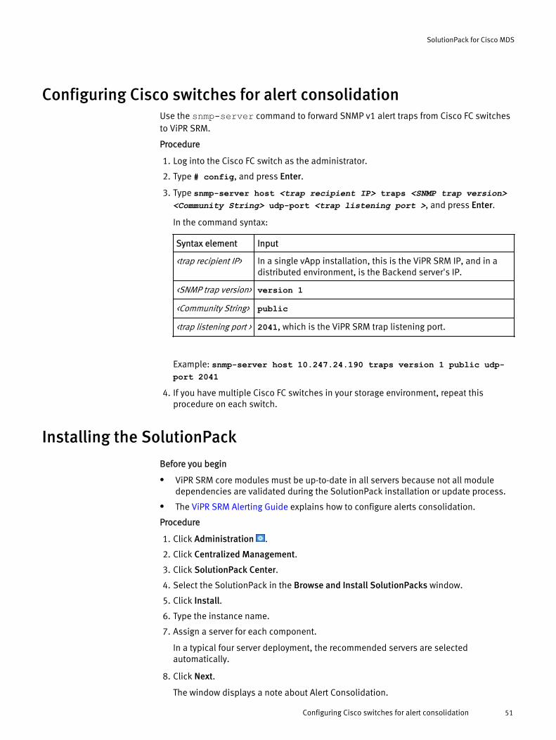
Configuring Cisco switches for alert consolidationUse the snmp-server command to forward SNMP v1 alert traps from Cisco FC switchesto ViPR SRM.
Procedure
1. Log into the Cisco FC switch as the administrator.
2. Type # config, and press Enter.
3. Type snmp-server host <trap recipient IP> traps <SNMP trap version><Community String> udp-port <trap listening port >, and press Enter.
In the command syntax:
Syntax element Input
<trap recipient IP> In a single vApp installation, this is the ViPR SRM IP, and in adistributed environment, is the Backend server's IP.
<SNMP trap version> version 1
<Community String> public
<trap listening port > 2041, which is the ViPR SRM trap listening port.
Example: snmp-server host 10.247.24.190 traps version 1 public udp-port 2041
4. If you have multiple Cisco FC switches in your storage environment, repeat thisprocedure on each switch.
Installing the SolutionPack
Before you begin
l ViPR SRM core modules must be up-to-date in all servers because not all moduledependencies are validated during the SolutionPack installation or update process.
l The ViPR SRM Alerting Guide explains how to configure alerts consolidation.
Procedure
1. Click Administration .
2. Click Centralized Management.
3. Click SolutionPack Center.
4. Select the SolutionPack in the Browse and Install SolutionPacks window.
5. Click Install.
6. Type the instance name.
7. Assign a server for each component.
In a typical four server deployment, the recommended servers are selectedautomatically.
8. Click Next.
The window displays a note about Alert Consolidation.
SolutionPack for Cisco MDS
Configuring Cisco switches for alert consolidation 51
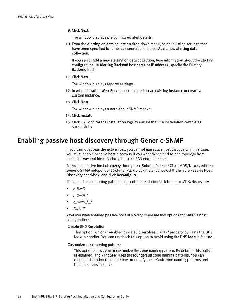
9. Click Next.
The window displays pre-configured alert details.
10. From the Alerting on data collection drop-down menu, select existing settings thathave been specified for other components, or select Add a new alerting datacollection.
If you select Add a new alerting on data collection, type information about the alertingconfiguration. In Alerting Backend hostname or IP address, specify the PrimaryBackend host.
11. Click Next.
The window displays reports settings.
12. In Administration Web-Service Instance, select an existing instance or create acustom instance.
13. Click Next.
The window displays a note about SNMP masks.
14. Click Install.
15. Click Ok. Monitor the installation logs to ensure that the installation completessuccessfully.
Enabling passive host discovery through Generic-SNMPIf you cannot access the active host, you cannot use active host discovery. In this case,you must enable passive host discovery if you want to see end-to-end topology fromhosts to array and identify chargeback on SAN enabled hosts.
To enable passive host discovery through the SolutionPack for Cisco MDS/Nexus, edit theGeneric-SNMP independent SolutionPack block instance, select the Enable Passive HostDiscovery checkbox, and click Reconfigure.
The default zone naming patterns supported in SolutionPack for Cisco MDS/Nexus are:
l z_%h%
l z_%h%_*
l z_%h%_*_*
l %h%_*
After you have enabled passive host discovery, there are two options for passive hostconfiguration:
Enable DNS Resolution
This option, which is enabled by default, resolves the "IP" property by using the DNSlookup handler. You can un-check this option to avoid using the DNS lookup feature.
Customize zone naming patterns
This option allows you to customize the zone naming pattern. By default, this optionis disabled, and ViPR SRM uses the four default zone naming patterns. You canenable this option to add, delete, or modify the default zone naming patterns andhost positions in zones.
SolutionPack for Cisco MDS
52 EMC ViPR SRM 3.7 SolutionPack Installation and Configuration Guide
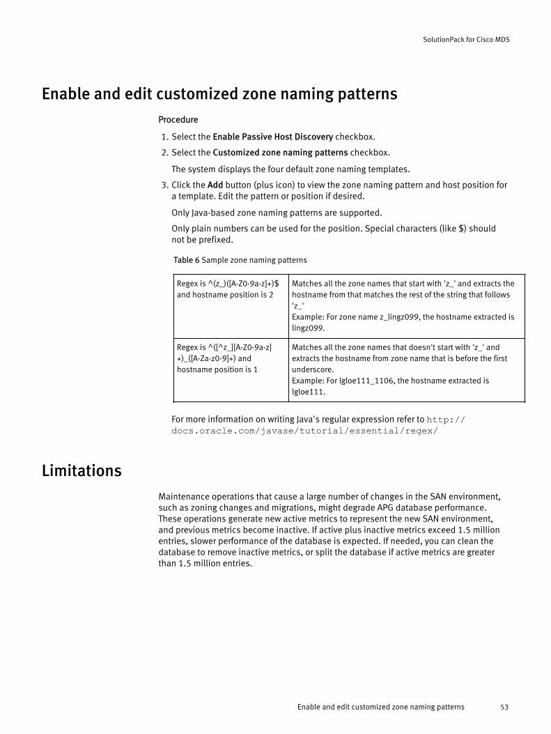
Enable and edit customized zone naming patternsProcedure
1. Select the Enable Passive Host Discovery checkbox.
2. Select the Customized zone naming patterns checkbox.
The system displays the four default zone naming templates.
3. Click the Add button (plus icon) to view the zone naming pattern and host position fora template. Edit the pattern or position if desired.
Only Java-based zone naming patterns are supported.
Only plain numbers can be used for the position. Special characters (like $) shouldnot be prefixed.
Table 6 Sample zone naming patterns
Regex is ^(z_)([A-Z0-9a-z]+)$and hostname position is 2
Matches all the zone names that start with 'z_' and extracts thehostname from that matches the rest of the string that follows'z_'Example: For zone name z_lingz099, the hostname extracted islingz099.
Regex is ^([^z_][A-Z0-9a-z]+)_([A-Za-z0-9]+) andhostname position is 1
Matches all the zone names that doesn't start with 'z_' andextracts the hostname from zone name that is before the firstunderscore.Example: For lgloe111_1106, the hostname extracted islgloe111.
For more information on writing Java's regular expression refer to http://docs.oracle.com/javase/tutorial/essential/regex/
LimitationsMaintenance operations that cause a large number of changes in the SAN environment,such as zoning changes and migrations, might degrade APG database performance.These operations generate new active metrics to represent the new SAN environment,and previous metrics become inactive. If active plus inactive metrics exceed 1.5 millionentries, slower performance of the database is expected. If needed, you can clean thedatabase to remove inactive metrics, or split the database if active metrics are greaterthan 1.5 million entries.
SolutionPack for Cisco MDS
Enable and edit customized zone naming patterns 53

SolutionPack for Cisco MDS
54 EMC ViPR SRM 3.7 SolutionPack Installation and Configuration Guide

CHAPTER 5
SolutionPack for Cisco UCS
l Overview............................................................................................................... 56l Configuring the UCS Manager................................................................................56l Installing the SolutionPack....................................................................................56l Importing the new database schema.....................................................................58
SolutionPack for Cisco UCS 55
OverviewThe SolutionPack for Cisco UCS generates reports that encompass compute, network,and storage access components of the unified fabric.
The SolutionPack generates uptime reports for the UCS Managers and enables you to seeinto the solution as managed by the unified management domain. In addition, theSolutionPack for Cisco UCS obtains real-time and historical data through various reportsthat indicate events and faults in the system.
Data collection methodsUCS XML API
Main reportsPower Consumption over Time
Fabric Interconnects
Chassis
System Statistics, Fans, PSU, Interfaces
Events
Configuring the UCS ManagerEnable XML API for the Cisco UCS Manager.
Before you begin
Procedure
1. Log in to the Cisco UCS Manager web console.
2. Navigate to Admin > Communication Management > Communication Services.
3. Verify that the HTTP & CIM XML services are enabled.
If the Redirect HTTP to HTTPS option is enabled, you will need to use securecommunication when configuring your SolutionPack block.
4. If you want to use secure communications between the collector and the UCSManager:
l Choose the secure communication option when adding the UCS Manager.
l Configure HTTPS on the Communication Services page of UCS Manager.
After you finish
EMC recommends that you create a new dedicated service account for SolutionPackintegration. Role-read-only role is sufficient for the SolutionPack to work properly.
Installing the SolutionPack
Before you begin
Core modules must be up-to-date in all servers because not all module dependencies arevalidated during the SolutionPack installation or update process.
SolutionPack for Cisco UCS
56 EMC ViPR SRM 3.7 SolutionPack Installation and Configuration Guide

Procedure
1. Click Administration .
2. Click Centralized Management.
3. Click SolutionPack Center.
4. Select the SolutionPack in the Browse and Install SolutionPacks window.
5. Click Install.
6. Type the instance name.
7. Assign a server for each component.
In a typical four server deployment, the recommended servers are selectedautomatically.
8. Click Next.
The window displays pre-configured alert details.
9. From the Alerting on data collection drop-down menu, select existing settings thathave been specified for other components, or select Add a new alerting datacollection.
If you select Add a new alerting on data collection, type information about the alertingconfiguration. In Alerting Backend hostname or IP address, specify the PrimaryBackend host.
10. Click Next.
The window displays data collection details.
11. From the Data collection drop-down menu, select existing settings that have beenspecified for other components, or select Add a new data collection.
If you select Add a new data collection, type information about the data collection. InHostname or IP address to send data to, use localhost on port 2020, which is theCollector host where the Load Balancer Connector is installed.
12. From the Frontend Web service drop-down menu, select existing settings that havebeen specified for other components, or select Add a new Frontend Web service.
If you select Add a new Frontend Web service, type information about the FrontendWeb service.
13. Select the Enable events collection checkbox.
14. In the Event server hostname or IP address field, select the Backend host where theevents server runs. The default port is 52007.
15. In the Even server port number field, enter a port number for events collection.
16. Select Configure advanced settings to configure polling settings.
17. Click Next.
The window displays event settings.
18. Select an Event database. If you select Add a new Events database, type informationfor the new events database. Type the database information for the events databasethat runs on the Primary Backend host. The default Database port is 53306. Thedefault Event server port number is 52007.
19. Click Next.
The window displays reports settings.
20. In Administration Web-Service Instance, select an existing instance or create acustom instance.
SolutionPack for Cisco UCS
Installing the SolutionPack 57

21. Click Install.
22. Click Ok. Monitor the installation logs to ensure that the installation completessuccessfully.
23. Click Discovery Center > Devices Management.
24. Click Cisco UCS.
25. Click Add new device.
26. Specify the details of the Cisco UCS configuration.
a. In the Device location section, select the server and instance where you want tostore the configuration details for this device.
b. In the UCS type field, select UCS Manager (Blade Chassis) or UCS C-Series (Server).
c. In Hostname or IP address type the UCS management host.
d. In the Username and Password fields, type the credentials for the managementserver.
e. Select Enable secure connection, if desired.
f. In the Communication port field, type the port number for the management server.
27. Click Test to validate the credentials.
28. Click OK.
29. Click Save.
After you finish
If you want to discover the Cisco UCS Fabric Interconnects in your environment via SNMP,you must install the Cisco MDS /Nexus SolutionPack in your environment to provide fullSNMP masks and capabilities for the SNMP discovery.
Cisco UCS events are commented out by default in frontend configuration files. To enableCisco UCS events, uncomment Cisco UCS events in the following configuration files:APG.xml, APG-WS.xml, and report-generation-config.xml.
Importing the new database schema
Before you begin
Starting with Watch4net 6.2u4, schema are preloaded. If you installed from an earlierversion, import the new database schema.
Procedure
1. Load the events block file Event-Processing/Generic-Live-Writer/cisco-ucs/ddl/my-ucs_live.sql.
2. Run mysql-client.sh (mysql-client.cmd on Windows).
3. Type username, database name, and password.
4. Copy the contents of the /my-ucs_live.sql file and paste it into the mysql clientat the mysql> prompt.
This creates the ucs_live table.
5. Start the event processing manager service.
6. To enable events reporting from the frontend:
SolutionPack for Cisco UCS
58 EMC ViPR SRM 3.7 SolutionPack Installation and Configuration Guide

a. Edit the Web-Application configuration file Web-Servers/Tomcat/Default/conf/Catalina/localhost/APG.xml.
b. If the cisco-ucs-events section is present, uncomment it.
c. If the cisco-ucs-events section is missing, add the following lines:
<!-- cisco-ucs-events --> <ResourceLink name="jdbc/FLOW-UCS-LIVE:{ mapping=FLOW-UCS.xml, table=ucs_live }" global="jdbc/FLOW-EVENTS" type="javax.sql.DataSource" />
7. Restart the tomcat service.
SolutionPack for Cisco UCS
Importing the new database schema 59

SolutionPack for Cisco UCS
60 EMC ViPR SRM 3.7 SolutionPack Installation and Configuration Guide
CHAPTER 6
SolutionPack for Converged Infrastructure
l Overview............................................................................................................... 62l Preparing Converged Infrastructure....................................................................... 62l Installing the SolutionPack....................................................................................62
SolutionPack for Converged Infrastructure 61
OverviewThe SolutionPack for Converged Infrastructure generates reports for hardware systemsummary, available capacity, hardware systems capacity by location, logical poolcapacity by type, and total capacity by service quality.
In addition, the SolutionPack obtains a topology view of the underlying system or serviceas discovered by the Unified Infrastructure Manager (UIM) view.
Data collection methodsThe XML collector is the only collector used to collect the data. Client must have UnitedInfrastructure Manager/Provisioning (UIM/P) and Unified Infrastructure Manager/Operations (UIM/O) virtual appliances installed in his environment with appropriateconnectivity before deploying the SolutionPack for Converged Infrastructure.
Main reportsVblock/VSPEX Inventory
UIM Dashboard
Topology
Supported collection interfacesFor information about supported collection interfaces, refer to the ViPR SRM SupportMatrix.
Preparing Converged InfrastructureIdentify the information required to support resource discovery and data collection beforeinstalling the SolutionPack for Converged Infrastructure.
ViPR SRM communicates with Unified Infrastructure Manager using credentials withaccess to the UIM host.
Procedure
1. Identify the user account credentials used to access the UIM host.
2. Record this information for use when you install the SolutionPack.
Installing the SolutionPack
Before you begin
l ViPR SRM core modules must be up-to-date in all servers because not all moduledependencies are validated during the SolutionPack installation or update process.
Procedure
1. Click Administration .
2. Click Centralized Management.
3. Click SolutionPack Center.
4. Select the SolutionPack in the Browse and Install SolutionPacks window.
5. Click Install.
6. Type the instance name.
7. Assign a server for each component.
SolutionPack for Converged Infrastructure
62 EMC ViPR SRM 3.7 SolutionPack Installation and Configuration Guide

In a typical four server deployment, the recommended servers are selectedautomatically.
8. Click Next.
The windows displays topology collector details.
9. From the Data collection drop-down menu, select existing settings that have beenspecified for other components, or select Add a new data collection.
If you select Add a new data collection, type information about the data collection. InHostname or IP address to send data to, use localhost on port 2020, which is theCollector host where the Load Balancer Connector is installed.
10. Leave Enable alerting on data collected checked.
11. From the Alerting on data collection drop-down menu, select existing settings thathave been specified for other components, or select Add a new alerting datacollection.
If you select Add a new alerting on data collection, type information about the alertingconfiguration. In Alerting Backend hostname or IP address, specify the PrimaryBackend host.
12. In the UIM/P hostname or IP address field, type the UIM/P host.
13. In the Username and Password fields, type the required credentials for the UIM/Phost.
14. In the UIM/O hostname or IP address field, type the UIM/P host.
15. In the Username and Password fields, type the required credentials for the UIM/Ohost.
16. Select Use advanced settings to configure polling settings.
17. Click Next.
The window displays reports settings.
18. From the Web-Service Gateway drop-down menu, select existing settings that havebeen specified for other components, or select Add a new Web-Service Gateway.
If you select Add a new Web-Service Gateway, type information about the web-servicegateway.
19. In Administration Web-Service Instance, select an existing instance or create acustom instance.
20. Click Install.
21. Click Ok. Monitor the installation logs to ensure that the installation completessuccessfully.
SolutionPack for Converged Infrastructure
Installing the SolutionPack 63

SolutionPack for Converged Infrastructure
64 EMC ViPR SRM 3.7 SolutionPack Installation and Configuration Guide

CHAPTER 7
SolutionPack for EMC Atmos
l Overview............................................................................................................... 66l Installing the SolutionPack....................................................................................66l Limitations............................................................................................................67
SolutionPack for EMC Atmos 65
OverviewThe SolutionPack accesses system summary reports for Resource Management Groups(RMGs), as well as for the nodes being monitored within the RMGs. In addition,SolutionPack generates reports summarizing key storage parameters for the entire Atmosmulti-tenant system.
Data collection methodsThe XML data collector is used to collect time series data. There are two sources of data:the Atmos System Management API and the Atmos Cloud Delivery Platform (ACDP).
Event Data from Atmos can be received using SNMP Traps. The M&R EPM server and theSNMP agent need to be configured in Atmos to send traps. Alternatively, the traps can besent to the SMARTS platform and the data can be populated using Smarts Listener.
Main reportsSystem Overview
RMG Summary
RMG Dashboard
Node Dashboard
Cluster Dashboard
Atmos cloud deliverery platform
ACDP Metering Data (Aggregated)
ACDP Nodes
Tenant Summary
Tenant Dashboard
Subtenant Dashboard
User Dashboard
Supported collection interfacesFor information about supported collection interfaces, refer to the ViPR SRM SupportMatrix.
Installing the SolutionPack
Before you begin
l EMC ViPR SRM core modules must be up-to-date in all servers because not all moduledependencies are validated during the SolutionPack installation or update process.
l Data imported in the 2.0 version of this SolutionPack will not be compatible with the1.0 version of SolutionPack for EMC Atmos. Data continuity with previously importeddata will be broken.
Procedure
1. Click Administration .
2. Click Centralized Management.
3. Click SolutionPack Center.
4. Select the SolutionPack in the Browse and Install SolutionPacks window.
SolutionPack for EMC Atmos
66 EMC ViPR SRM 3.7 SolutionPack Installation and Configuration Guide

5. Click Install.
6. Type the instance name.
7. Assign a server for each component.
In a typical four server deployment, the recommended servers are selectedautomatically.
8. Click Next.
The window displays data collection details.
9. From the Data collection drop-down menu, select existing settings that have beenspecified for other components, or select Add a new data collection.
If you select Add a new data collection, type information about the data collection. InHostname or IP address to send data to, use localhost on port 2020, which is theCollector host where the Load Balancer Connector is installed.
10. Make a selection in the EMC Atmos field. If you select Add a new EMC Atmos, enterthe Atmos configuration settings.
11. Configure polling settings.
12. Click Next.
The window displays reports settings.
13. In Administration Web-Service Instance, select an existing instance or create acustom instance.
14. Click Install.
15. Click Ok. Monitor the installation logs to ensure that the installation completessuccessfully.
LimitationsThe Atmos SMI interface reports capacity based on the storage available for objectcreation, while ViPR SRM reports combined object storage capacity along with thecapacity used to store the object's metadata. Therefore the ViPR SRM number will behigher than the number reported by the Atmos SMI console, the difference being thecapacity dedicated to metadata storage.
SolutionPack for EMC Atmos
Limitations 67

SolutionPack for EMC Atmos
68 EMC ViPR SRM 3.7 SolutionPack Installation and Configuration Guide
CHAPTER 8
SolutionPack for EMC Centera
l Overview............................................................................................................... 70l Preparing Centera arrays for discovery and data collection.................................... 70l Installing the SolutionPack....................................................................................71l Limitations............................................................................................................72
SolutionPack for EMC Centera 69
OverviewThe SolutionPack accesses the inventory of the Centera storage system and generatesreports on usage capacity for pools and nodes, pool file counts, and c-clip counts.
Supported systemsCentera Viewer CLI (v4.3)
Data collection methodsCLI
Main reportsCentera Cluster Summary
Pool usage details
Node detail
Utilization
Supported collection interfacesFor information about supported collection interfaces, refer to the ViPR SRM SupportMatrix.
Preparing Centera arrays for discovery and data collectionProcedure
1. Identify the ViPR SRM Collector host which supports EMC Centera Viewer CLI software.
2. Identify the username (with monitor role enabled) and password.
3. Record this information. You need it to install the SolutionPack.
Configuring Centera arrays for alert consolidationUse the set snmp target command to forward SNMP v1 traps from Centera to ViPRSRM.
Procedure
1. Log into the Centera as the administrator.
2. Type set snmp target, and press Enter.
3. Enter the following details, when prompted:
Option Input
Management station: <trap_recipient_IP_address> : 2041In a single vApp installation, <trap_recipient_IP_address> isthe ViPR SRM IP address. In a distributed environment,<trap_recipient_IP_address> is the Backend server IPaddress.
SNMP version (v2, v3)[v2]:
v2
Community name: public
SolutionPack for EMC Centera
70 EMC ViPR SRM 3.7 SolutionPack Installation and Configuration Guide
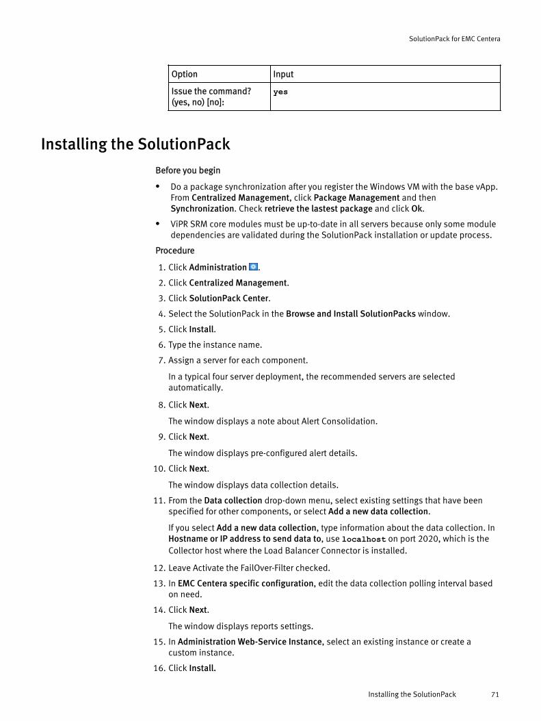
Option Input
Issue the command?(yes, no) [no]:
yes
Installing the SolutionPack
Before you begin
l Do a package synchronization after you register the Windows VM with the base vApp.From Centralized Management, click Package Management and thenSynchronization. Check retrieve the lastest package and click Ok.
l ViPR SRM core modules must be up-to-date in all servers because only some moduledependencies are validated during the SolutionPack installation or update process.
Procedure
1. Click Administration .
2. Click Centralized Management.
3. Click SolutionPack Center.
4. Select the SolutionPack in the Browse and Install SolutionPacks window.
5. Click Install.
6. Type the instance name.
7. Assign a server for each component.
In a typical four server deployment, the recommended servers are selectedautomatically.
8. Click Next.
The window displays a note about Alert Consolidation.
9. Click Next.
The window displays pre-configured alert details.
10. Click Next.
The window displays data collection details.
11. From the Data collection drop-down menu, select existing settings that have beenspecified for other components, or select Add a new data collection.
If you select Add a new data collection, type information about the data collection. InHostname or IP address to send data to, use localhost on port 2020, which is theCollector host where the Load Balancer Connector is installed.
12. Leave Activate the FailOver-Filter checked.
13. In EMC Centera specific configuration, edit the data collection polling interval basedon need.
14. Click Next.
The window displays reports settings.
15. In Administration Web-Service Instance, select an existing instance or create acustom instance.
16. Click Install.
SolutionPack for EMC Centera
Installing the SolutionPack 71

17. Click Ok. Monitor the installation logs to ensure that the installation completessuccessfully.
18. Click Discovery Center > Devices Management.
19. Click Centera Configuration.
These steps describe how to add hosts individually. For information about usingdiscovery groups to use the same credentials to discover multiple hosts, see Addingdevices to discovery groups on page 274.
20. Click Add New Device.
21. From Server, select the server where the device will be dispatched.
22. From Instance, select the instance of the emc-centera where the device will bedispatched.
23. In the Centera configuration section, enter the IP and credentials of the Centeraarray’s Management IP address or hostname.
a. In Management IP address or hostname, type the array management IP orhostname.
b. Add the username and password of the Centera array.
c. Chose the Connection method from the drop-down menu.
24. Click Test to validate the credentials.
25. Click Ok.
26. Click Save in the Centera Configuration page.
Limitationsl If a Centera system does not have its serial number configured, it will be reported in a
separate table. If there are two or more systems that do not have their serial numberconfigured, the Capacity information will be incorrect.
l The Centera Device Summary report in Explore does not display Health alerts. It onlydisplays Threshold alerts.
l Health alerts are not displayed in the Devices Summary report.
SolutionPack for EMC Centera
72 EMC ViPR SRM 3.7 SolutionPack Installation and Configuration Guide
CHAPTER 9
SolutionPack for EMC Data Domain
l Overview............................................................................................................... 74l Preparing EMC Data Domain for discovery and data collection...............................74l Configuring Data Domain devices for alert consolidation....................................... 74l Installing the SolutionPack ...................................................................................75l Discover the SNMP Collector................................................................................. 76
SolutionPack for EMC Data Domain 73
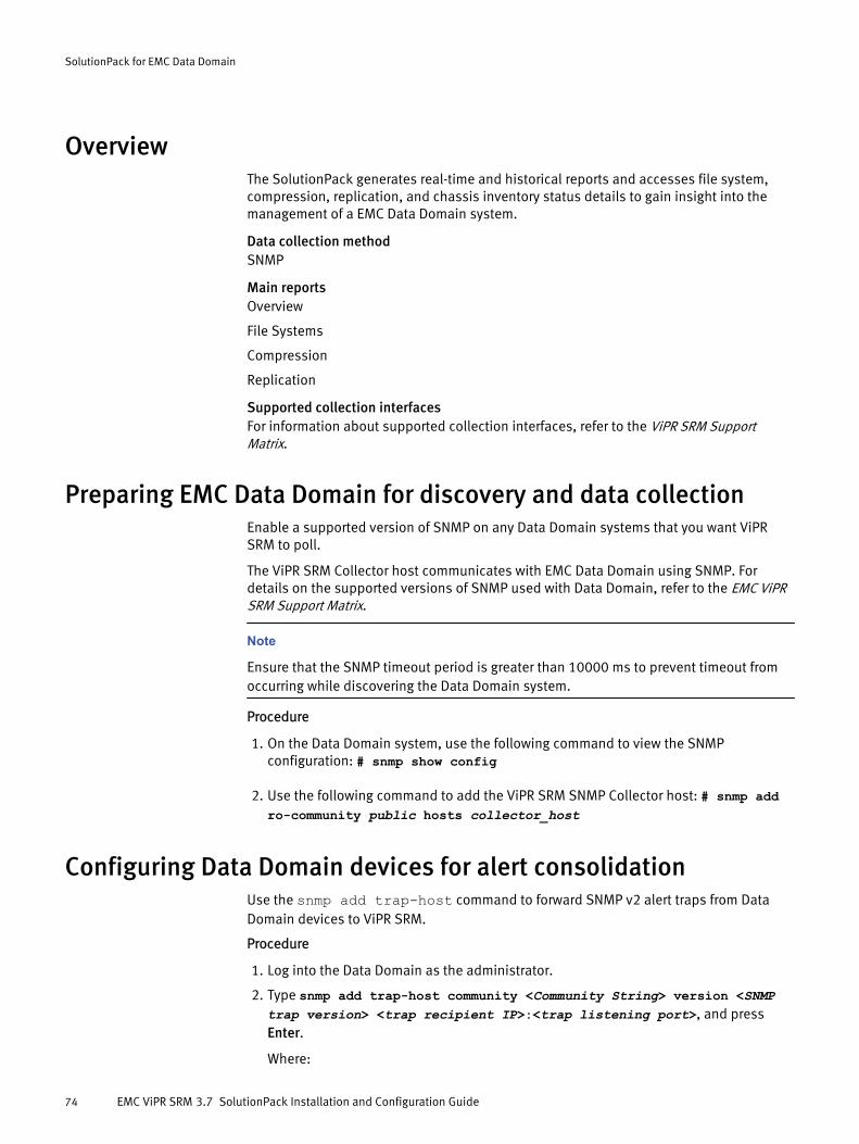
OverviewThe SolutionPack generates real-time and historical reports and accesses file system,compression, replication, and chassis inventory status details to gain insight into themanagement of a EMC Data Domain system.
Data collection methodSNMP
Main reportsOverview
File Systems
Compression
Replication
Supported collection interfacesFor information about supported collection interfaces, refer to the ViPR SRM SupportMatrix.
Preparing EMC Data Domain for discovery and data collectionEnable a supported version of SNMP on any Data Domain systems that you want ViPRSRM to poll.
The ViPR SRM Collector host communicates with EMC Data Domain using SNMP. Fordetails on the supported versions of SNMP used with Data Domain, refer to the EMC ViPRSRM Support Matrix.
Note
Ensure that the SNMP timeout period is greater than 10000 ms to prevent timeout fromoccurring while discovering the Data Domain system.
Procedure
1. On the Data Domain system, use the following command to view the SNMPconfiguration: # snmp show config
2. Use the following command to add the ViPR SRM SNMP Collector host: # snmp addro-community public hosts collector_host
Configuring Data Domain devices for alert consolidationUse the snmp add trap-host command to forward SNMP v2 alert traps from DataDomain devices to ViPR SRM.
Procedure
1. Log into the Data Domain as the administrator.
2. Type snmp add trap-host community <Community String> version <SNMPtrap version> <trap recipient IP>:<trap listening port>, and pressEnter.
Where:
SolutionPack for EMC Data Domain
74 EMC ViPR SRM 3.7 SolutionPack Installation and Configuration Guide
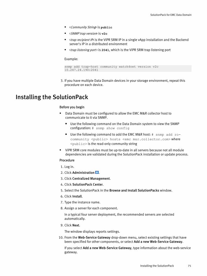
l <Community String> is publicl <SNMP trap version> is v2cl <trap recipient IP> is the ViPR SRM IP in a single vApp installation and the Backend
server's IP in a distributed environment
l <trap listening port > is 2041, which is the ViPR SRM trap listening port
Example:
snmp add trap-host community watch4net version v2c 10.247.24.190:2041
3. If you have multiple Data Domain devices in your storage environment, repeat thisprocedure on each device.
Installing the SolutionPack
Before you begin
l Data Domain must be configured to allow the EMC M&R collector host tocommunicate to it via SNMP.
n Use the following command on the Data Domain system to view the SNMPconfiguration: # snmp show config
n Use the following command to add the EMC M&R host: # snmp add ro-community <public> hosts <emc m&r.collector.com> where<public> is the read-only community string
l ViPR SRM core modules must be up-to-date in all servers because not all moduledependencies are validated during the SolutionPack installation or update process.
Procedure
1. Log in.
2. Click Administration .
3. Click Centralized Management.
4. Click SolutionPack Center.
5. Select the SolutionPack in the Browse and Install SolutionPacks window.
6. Click Install.
7. Type the instance name.
8. Assign a server for each component.
In a typical four server deployment, the recommended servers are selectedautomatically.
9. Click Next.
The window displays reports settings.
10. From the Web-Service Gateway drop-down menu, select existing settings that havebeen specified for other components, or select Add a new Web-Service Gateway.
If you select Add a new Web-Service Gateway, type information about the web-servicegateway.
SolutionPack for EMC Data Domain
Installing the SolutionPack 75

11. In Administration Web-Service Instance, select an existing instance or create acustom instance.
12. Click Next.
13. Click Install.
14. Click Ok. Monitor the installation logs to ensure that the installation completessuccessfully.
Discover the SNMP CollectorProcedure
1. Log in to EMC M&R.
Use http://<localhost>:58080/device-discovery/.
2. Go to Collector > New Collector.
This option collects configuration data from the SNMP Collector.
3. Click Save.
4. The Collector is listed with orange color in the STATE column.
5. Click Check reachability of the x selected collector(s) to verify that the collector isreachable, and if it is, click Send configurations to the x selected collector(s).
The Collector is listed with green color in STATE.
6. Select Devices and click New Device.
7. Fill in the details for the new device on all tabs.
8. Click Save.
If the STATE column is green for the device, no error occurred. If an error occurred,mouseover the STATE column for the device to display the error.
9. If STATE is green, click Execute Action. This will discover the device with thecapabilities that are selected.
10. Go to the Dashboard and send the configurations.
11. Go to the device and check that the Collector is listed.
After you finish
If all steps are successful, device details begin to appear in the ViPR SRM User Interface.
If you encounter any problems, use the Events Log to begin troubleshooting. For example,the log might point to problems with SNMP communications or configuration settings. Toopen the log, scroll to the bottom of the Device Discovery pane (http://<localhost>:58080/device-discovery/#/devices) and click Show EventsLog.
SolutionPack for EMC Data Domain
76 EMC ViPR SRM 3.7 SolutionPack Installation and Configuration Guide
CHAPTER 10
SolutionPack for EMC Data Protection Advisor
l Overview............................................................................................................... 78l Installing the SolutionPack....................................................................................78l Verifying scheduled reports in DPA........................................................................80l Troubleshooting report generation errors...............................................................80l Limitations............................................................................................................80
SolutionPack for EMC Data Protection Advisor 77
OverviewThis SolutionPack enables users to generate real-time and historical reports onreplication technologies, EMC Data Domain backup-to-disk platform, backuptechnologies for Symantec Netbackup, and EMC Avamar supported by Data ProtectionAdvisor.
Data collection methodsThe SolutionPack collector uses REST API requests to fetch XML report files from the DPAserver (<EMC DPA Installation directory>\EMC\services\shared\report-results\scheduled\<backuptechnology-selected>). When DPAis added to Discovery Center, scheduled reports are created and generated once a week.Once the scheduled reports are generated, report data is collected hourly.
The Stream Collector uses REST APIs to collect the data for the following:
l Symantec-NetBackup
l EMC-Avamar
l EMC-NetWorker
l IBM-Tivoli-Storage-Manager
l EMC-Recover Point
l Data Domain
Main reportsReplication: RPO Compliance, Capacity
Symantec-NetBackup: Inventory, BackupSummary, RestoreSummary, Client Reports
EMC-Avamar: Inventory, BackupSummary, RestoreSummary, Client Reports
EMC-NetWorker: Inventory, BackupSummary, RestoreSummary, Client Reports
IBM-Tivoli-Storage-Manager: Inventory, BackupSummary, RestoreSummary, ClientReports
Installing the SolutionPack
Before you begin
l ViPR SRM core modules must be up-to-date in all servers because not all moduledependencies are validated during the SolutionPack installation or update process.
Procedure
1. Click Administration .
2. Click Centralized Management.
3. Click SolutionPack Center.
4. Select the SolutionPack in the Browse and Install SolutionPacks window.
5. Click Install.
6. Type the instance name.
7. Assign a server for each component.
In a typical four server deployment, the recommended servers are selectedautomatically.
SolutionPack for EMC Data Protection Advisor
78 EMC ViPR SRM 3.7 SolutionPack Installation and Configuration Guide

8. Click Next.
The window displays a note about Alert Consolidation.
9. Click Next.
The window displays data collection details.
10. From the Data collection drop-down menu, select existing settings that have beenspecified for other components, or select Add a new data collection.
If you select Add a new data collection, type information about the data collection. InHostname or IP address to send data to, use localhost on port 2020, which is theCollector host where the Load Balancer Connector is installed.
11. From the Alert Consolidation drop-down menu, select existing settings that have beenspecified for other components, or select Add a new Alert consolidation.
If you select Add a new Alert consolidation, type information about the alertconfiguration. In Alerting HostName or IP address, use localhost on port 2020,which is the Collector host where the Load Balancer Connector is installed.
12. Select the backup technologies to monitor.
If you do not select any of these options, there will be no DPA reports to collect. If youselect all of these options, data will be collected for all DPA reports.
13. Select Enable EMC DataProtectionAdvisor Alerts.
14. Select Do you want to configure advanced settings to configure the alert pollinginterval.
By default, the polling interval for Data Protection Advisor backup alerts is 5 minutes.You can change the polling period to 30 minutes.
15. Click Next.
The window displays reports settings.
16. Click Install.
17. Click Ok. Monitor the installation logs to ensure that the installation completessuccessfully.
18. Click Discovery Center > Devices Management.
19. Click EMC Data Protection Advisor.
20. Click Add new device.
21. In DPA appliance Host name or IP, type the host information for the DPA appliance.
22. Provide the access credentials for the DPA appliance.
23. Provide the protocol and DPA server port.
24. Click Test to validate the credentials.
25. Click Ok.
26. Click Save.
DPA requires specific licenses to monitor replication technologies, backuptechnologies, and Data Domain. These licenses must be installed on DPA for ViPRSRM to monitor these technologies.
DPA reports may take up to one hour to populate. Some of the performance data/graphs take two collection cycles for the graphs to be plotted.
SolutionPack for EMC Data Protection Advisor
Installing the SolutionPack 79
After installing the SolutionPack for EMC Data Protection Advisor, there may bescheduling related errors in the collector logs.
Verifying scheduled reports in DPAOnce DPA is added to Discovery Center, ViPR SRM connects to DPA with the usernamespecified and creates scheduled reports for the backup technology selected.
Procedure
1. Login to DPA.
2. Navigate to Reports > Report Jobs > Scheduled reports.
Report names starting with W4N - should be created hourly.
3. On the DPA server console, XML files should be seen in the directory <EMC DPAInstallation directory>\EMC\services\shared\report-results\scheduled\<backuptechnology-selected>.
Troubleshooting report generation errorsReconfigure the data collection options in the SolutionPack for EMC Data ProtectionAdvisor if reports are not being generated. This procedure applies to each DPA instancefor which reports are not being generated.
Procedure
1. Click Administration .
2. Click Centralized Management.
3. Click SolutionPacks.
4. Click EMC Data Protection Advisor.
5. Within the Instance column, click on the edit icon to reconfigure the Data Collectioncomponent.
6. Select the technology you want to collect data from.
7. Select Do you want to configure advanced settings and enable Number of collectingthreads, if required.
8. Click Reconfigure.
LimitationsWhile updating the SolutionPack from 3.5.x to 3.7, you need to select advanced settingsand select the backup technology required. This is due to the fact that Avamar andNetbackup Technology Support was introduced from 3.6. For updates to 3.7, you need tojust select the backup technology required.
SolutionPack for EMC Data Protection Advisor
80 EMC ViPR SRM 3.7 SolutionPack Installation and Configuration Guide
CHAPTER 11
SolutionPack for EMC ECS
l Overview............................................................................................................... 82l Installing the SolutionPack for EMC ECS................................................................ 85l Remove old ECS hosts from the Physical Host SP...................................................87l Expand ECS...........................................................................................................87l Limitations............................................................................................................88
SolutionPack for EMC ECS 81

OverviewThe SolutionPack for EMC ECS 2.x collects inventory, capacity, performance, and healthmetrics for object storage on EMC ECS 2.x systems. Detailed metrics for the virtual datacenters, nodes, and disks for object storage managed by ECS are included.
Licenses and installation scenariosThe SolutionPack for EMC ECS 2.x supports two licensing scenarios.
Note
These scenarios require a ViPR SRM 3.7.1 or greater installation to support ECS 2.2.
ECS Reporting
ECS Reporting is an optional feature of ECS 2.x. It provides reporting for ECS 2.x in alimited version of ViPR SRM. For this feature, the SolutionPack for EMC ECS installsthe following features:
l Basic set of reports about ECS 2.x resources in the Report Library node of ViPRSRM
l Consolidated alerts and health in the global Operations reports
ECS Reporting requires the VIPR_ECS_SP ELMS license embedded in the ViPR SRMlicense file. If you upgraded from a previous version of ECS, you have this license.For new ECS installations, you received a ViPR SRM license file containing thislicense with the ECS purchase.
Full EMC ViPR SRM
Full ViPR SRM discovers, collect metrics for, and reports on an enterprise-widestorage environment. Global reports merge capacity, chargeback, storage usage,operational, and performance information across all storage platforms, providing acomprehensive view of the entire storage infrastructure. For a full ViPR SRMinstallation, the SolutionPack for EMC ECS installs the following features:
l Basic set of reports about ECS 2.x resources in the Report Library node of ViPRSRM
l Consolidated alerts and health in the global Operations reports
l ECS object capacity metrics merged into the global capacity Dashboards andExplore reports
l Additional inventory reports for ECS Namespaces and Buckets added to theReport Library
l Chargeback reporting for ECS object storage, by Namespace and Bucket,including computed costs by service level
l A new Bucket Service Level group based on replication policy, with costassignments and capability to create custom service levels
To get all of the above features requires the VIPRSRM_ECS_TB ELMS licenseembedded in the ViPR SRM license file. You receive this license with the purchase ofthe SolutionPack for EMC ECS and ViPR SRM.
For information about installing license files, refer to the ViPR SRM Administrator's Guide.
SolutionPack for EMC ECS
82 EMC ViPR SRM 3.7 SolutionPack Installation and Configuration Guide

Main reports
Summary Reports
Degraded or Bad Disks
Identifies rack and node location, disk ID, and affected storage pool. Providesdrill-down into health and stress factors.
Degraded or Bad Nodes
Summarizes health statistics by node and supports drill-down into health andstress factors.
Health Dashboard/Virtual Data Centers
Shows general health and stress ratings; percentages of CPU usage, memoryusage, and network usage; and network bandwidth rate. Provides drill-downcapabilities into nodes, and then into services and disks of each node.
Health Dashboard/Remote Replication Status
Shows the local and remote virtual data center pairings and status of each.Supports drill-down into each replication group for graphs of the table columns.
Inventory Reports
Namespaces (available only with full ViPR SRM license)
For each namespace, provides bucket and object counts, bucket owners,objects created and deleted during the reporting period, amount of datauploaded and downloaded during the reporting period, namespace quota, andamounts and percentage of quota used. Supports drill-down into buckets withina namespace and other namespace details.
Nodes
By physical node and storage pool, shows number of associated disks, andamount of Usable, Used, and Available storage capacity. Also shows rack ID andversion of node and supports drill-down into a node's disks.
Replication Groups
For each group, shows number of virtual data centers and buckets. Click a groupname to display the storage pools in that group. Supports drill-down into nodesand disks.
Storage Pools
Summarizes number of nodes and number of disks in each storage pool, andshows total amount of Used and Available capacity per storage pool. Supportsdrill-down into nodes and then disks.
Virtual Data Centers
Provides the management IP address for each virtual data center, andsummarizes Usable, Used, and Available capacity in various dashboard reports.Click a data center to see its capacity, storage pools, and nodes.
Performance Reports
Nodes
For each node, shows data transfer metrics for transactions, disks, andnetworks. Also shows transaction error rate per node. Supports drill-down intographs for each column.
SolutionPack for EMC ECS
Overview 83

Storage Pools
For each storage pool, shows data transfer metrics for transactions, disks, andnetworks. Also shows transaction error rate per storage pool. Supports drill-down into graphs for each column.
Virtual Data Centers
For each virtual data center, shows data transfer metrics for transactions, disks,and networks. Also shows transaction error rate per virtual data center.Supports drill-down into graphs for each column.
Remote Replication Status
For each replication group, shows local and remote virtual data centers, ingressand egress data transfer rates, and percentage of progress on bootstrap andfailover processes.
Capacity Reports
These reports show object capacity.
Configured Usable Capacity and Trends
Summarizes metrics for configured free, configured used, and reserved forsystem use. A trend report shows enterprise-wide historical usable capacity.Provides drill-down into storage pools and various graphs.
Object Count Trend
Shows enterprise-wide historical object count usage.
Used Capacity by Purpose
Summarizes used capacity by unprotected (not replicated), locally protected,remotely protected, and system used.
Storage Pools
Summarizes each storage pool, showing virtual data center, numbers of nodesand disks, and amount of usable, used, and available storage.
Operations Reports
Health Dashboard
Shows general health and stress ratings; percentages of CPU usage, memoryusage, and network usage; and network bandwidth rate. Provides drill-downcapabilities into nodes, and then into services and disks of each node.
Situations to Watch
The following reports flag possible developing problems:
l Buckets Near Quota
l Degraded or Bad Disks
l Degraded or Bad Nodes
l Namespaces Near Quota
Global Chargeback Reports (available only with full ViPR SRM license)
Object chargeback reports appear in the ViPR SRM global Dashboard area.
l Chargeback by Namespace shows namespace usage by characteristics such asLocally vs Remotely protected, object counts, data downloads/uploads, buckets
SolutionPack for EMC ECS
84 EMC ViPR SRM 3.7 SolutionPack Installation and Configuration Guide
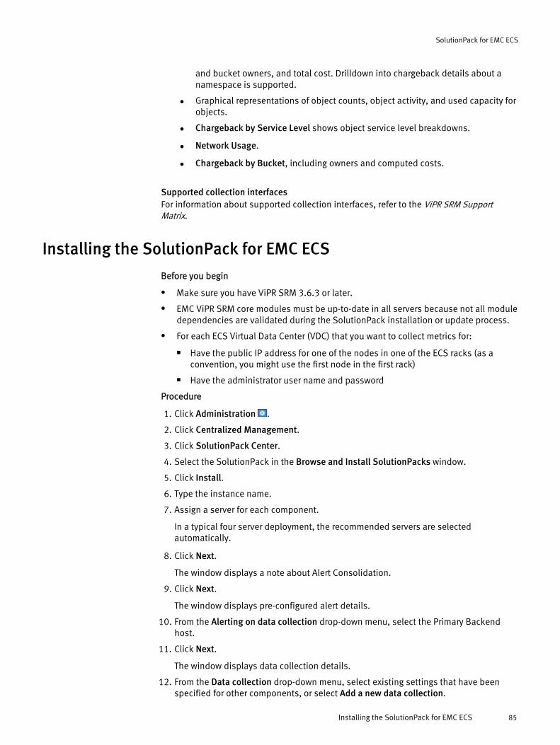
and bucket owners, and total cost. Drilldown into chargeback details about anamespace is supported.
l Graphical representations of object counts, object activity, and used capacity forobjects.
l Chargeback by Service Level shows object service level breakdowns.
l Network Usage.
l Chargeback by Bucket, including owners and computed costs.
Supported collection interfacesFor information about supported collection interfaces, refer to the ViPR SRM SupportMatrix.
Installing the SolutionPack for EMC ECS
Before you begin
l Make sure you have ViPR SRM 3.6.3 or later.
l EMC ViPR SRM core modules must be up-to-date in all servers because not all moduledependencies are validated during the SolutionPack installation or update process.
l For each ECS Virtual Data Center (VDC) that you want to collect metrics for:
n Have the public IP address for one of the nodes in one of the ECS racks (as aconvention, you might use the first node in the first rack)
n Have the administrator user name and password
Procedure
1. Click Administration .
2. Click Centralized Management.
3. Click SolutionPack Center.
4. Select the SolutionPack in the Browse and Install SolutionPacks window.
5. Click Install.
6. Type the instance name.
7. Assign a server for each component.
In a typical four server deployment, the recommended servers are selectedautomatically.
8. Click Next.
The window displays a note about Alert Consolidation.
9. Click Next.
The window displays pre-configured alert details.
10. From the Alerting on data collection drop-down menu, select the Primary Backendhost.
11. Click Next.
The window displays data collection details.
12. From the Data collection drop-down menu, select existing settings that have beenspecified for other components, or select Add a new data collection.
SolutionPack for EMC ECS
Installing the SolutionPack for EMC ECS 85

If you select Add a new data collection, type information about the data collection. InHostname or IP address to send data to, use localhost on port 2020, which is theCollector host where the Load Balancer Connector is installed.
13. From the Alert Consolidation drop-down menu, select existing settings that have beenspecified for other components, or select Add a new Alert consolidation.
If you select Add a new Alert consolidation, type information about the alertingconfiguration. In Alerting Backend hostname or IP address, specify the PrimaryBackend host.
14. Select Use advanced settings to configure polling settings or to disable a polling type.
15. In each polling period drop-down menu, select a polling period or select Disabled toturn off the polling.
16. Click Next.
The window displays reports settings.
17. Click Install.
18. Click Ok. Monitor the installation logs to ensure that the installation completessuccessfully.
19. Click Discovery Center > Devices Management.
20. Click EMC ECS.
21. Click Add new device.
For ECS, a device is a VDC, and the term ECS system refers to a VDC. A VDC consists ofone or more ECS appliances (racks) with 4 or 8 nodes each and attached storagesystems.
In a multi-site federation of VDCs, provide information for each VDC as a separatedevice.
22. Verify that the first two fields are correct for the collection instance.
23. In Virtual Data Center name, type the VDC name as configured in ECS.
24. In IP address or host name, provide the public IP address for one of the nodes in oneof the ECS racks in the VDC. For example, use the public IP address for the first nodein the first rack in the VDC.
25. For Username and Password, provide the administrator credentials configured for theVDC.
The authentication user account must have System Administrator privileges on theECS system. On ECS, navigate to Manage > Users > Management Users > accountname,and make sure the System Administrator field is set to Yes.
26. For Configured for remote replication, check this box if the VDC is part of a geo-replicated federation of VDCs.
When you check this box, the Collect namespace and bucket data field appears.
27. In Collect namespace and bucket data, check this box for only one of the VDCs in ageo-replicated federation of VDCs.
This field configures the one VDC in the geo-replicated federation that provides thenamespace and bucket metrics for reporting.
SolutionPack for EMC ECS
86 EMC ViPR SRM 3.7 SolutionPack Installation and Configuration Guide
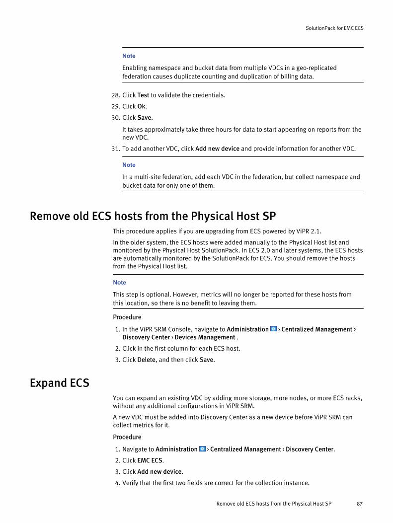
Note
Enabling namespace and bucket data from multiple VDCs in a geo-replicatedfederation causes duplicate counting and duplication of billing data.
28. Click Test to validate the credentials.
29. Click Ok.
30. Click Save.
It takes approximately take three hours for data to start appearing on reports from thenew VDC.
31. To add another VDC, click Add new device and provide information for another VDC.
Note
In a multi-site federation, add each VDC in the federation, but collect namespace andbucket data for only one of them.
Remove old ECS hosts from the Physical Host SPThis procedure applies if you are upgrading from ECS powered by ViPR 2.1.
In the older system, the ECS hosts were added manually to the Physical Host list andmonitored by the Physical Host SolutionPack. In ECS 2.0 and later systems, the ECS hostsare automatically monitored by the SolutionPack for ECS. You should remove the hostsfrom the Physical Host list.
Note
This step is optional. However, metrics will no longer be reported for these hosts fromthis location, so there is no benefit to leaving them.
Procedure
1. In the ViPR SRM Console, navigate to Administration > Centralized Management >Discovery Center > Devices Management .
2. Click in the first column for each ECS host.
3. Click Delete, and then click Save.
Expand ECSYou can expand an existing VDC by adding more storage, more nodes, or more ECS racks,without any additional configurations in ViPR SRM.
A new VDC must be added into Discovery Center as a new device before ViPR SRM cancollect metrics for it.
Procedure
1. Navigate to Administration > Centralized Management > Discovery Center.
2. Click EMC ECS.
3. Click Add new device.
4. Verify that the first two fields are correct for the collection instance.
SolutionPack for EMC ECS
Remove old ECS hosts from the Physical Host SP 87
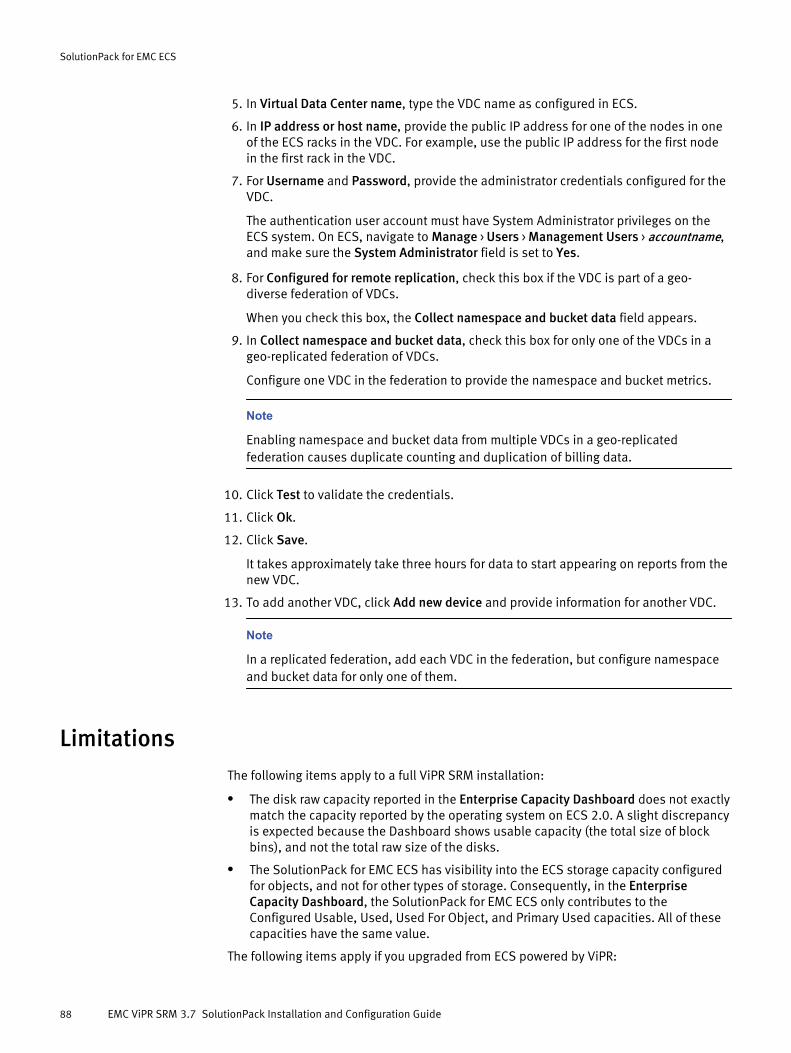
5. In Virtual Data Center name, type the VDC name as configured in ECS.
6. In IP address or host name, provide the public IP address for one of the nodes in oneof the ECS racks in the VDC. For example, use the public IP address for the first nodein the first rack in the VDC.
7. For Username and Password, provide the administrator credentials configured for theVDC.
The authentication user account must have System Administrator privileges on theECS system. On ECS, navigate to Manage > Users > Management Users > accountname,and make sure the System Administrator field is set to Yes.
8. For Configured for remote replication, check this box if the VDC is part of a geo-diverse federation of VDCs.
When you check this box, the Collect namespace and bucket data field appears.
9. In Collect namespace and bucket data, check this box for only one of the VDCs in ageo-replicated federation of VDCs.
Configure one VDC in the federation to provide the namespace and bucket metrics.
Note
Enabling namespace and bucket data from multiple VDCs in a geo-replicatedfederation causes duplicate counting and duplication of billing data.
10. Click Test to validate the credentials.
11. Click Ok.
12. Click Save.
It takes approximately take three hours for data to start appearing on reports from thenew VDC.
13. To add another VDC, click Add new device and provide information for another VDC.
Note
In a replicated federation, add each VDC in the federation, but configure namespaceand bucket data for only one of them.
LimitationsThe following items apply to a full ViPR SRM installation:
l The disk raw capacity reported in the Enterprise Capacity Dashboard does not exactlymatch the capacity reported by the operating system on ECS 2.0. A slight discrepancyis expected because the Dashboard shows usable capacity (the total size of blockbins), and not the total raw size of the disks.
l The SolutionPack for EMC ECS has visibility into the ECS storage capacity configuredfor objects, and not for other types of storage. Consequently, in the EnterpriseCapacity Dashboard, the SolutionPack for EMC ECS only contributes to theConfigured Usable, Used, Used For Object, and Primary Used capacities. All of thesecapacities have the same value.
The following items apply if you upgraded from ECS powered by ViPR:
SolutionPack for EMC ECS
88 EMC ViPR SRM 3.7 SolutionPack Installation and Configuration Guide

l The SolutionPack for EMC ECS applies to ECS 2.0 and later. For metrics on earlierversions of ECS, use the SolutionPack for EMC ViPR Controller that was delivered withthe earlier ECS system.
l The Dashboards > Storage > Object Chargeback report is an artifact from the earliersystem. After you upgrade all ECS systems, the metrics in this report will age out butthe report itself will remain visible.
l For this patch release of the SolutionPack for EMC ECS, the new ECS chargebackreport is temporarily located under Report Library > EMC ECS > Operations.
SolutionPack for EMC ECS
Limitations 89

SolutionPack for EMC ECS
90 EMC ViPR SRM 3.7 SolutionPack Installation and Configuration Guide
CHAPTER 12
SolutionPack for EMC Host Interface
l Overview............................................................................................................... 92l Installing the SolutionPack....................................................................................92l Recommendations................................................................................................ 93l Limitations............................................................................................................94
SolutionPack for EMC Host Interface 91
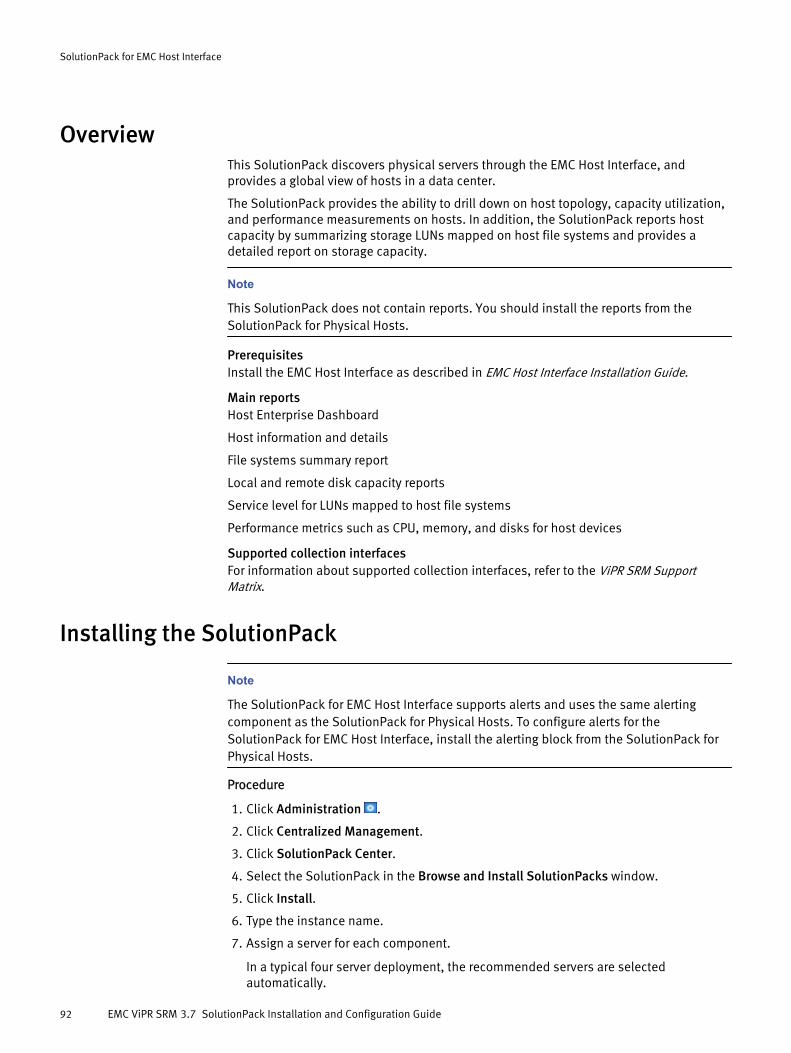
OverviewThis SolutionPack discovers physical servers through the EMC Host Interface, andprovides a global view of hosts in a data center.
The SolutionPack provides the ability to drill down on host topology, capacity utilization,and performance measurements on hosts. In addition, the SolutionPack reports hostcapacity by summarizing storage LUNs mapped on host file systems and provides adetailed report on storage capacity.
Note
This SolutionPack does not contain reports. You should install the reports from theSolutionPack for Physical Hosts.
PrerequisitesInstall the EMC Host Interface as described in EMC Host Interface Installation Guide.
Main reportsHost Enterprise Dashboard
Host information and details
File systems summary report
Local and remote disk capacity reports
Service level for LUNs mapped to host file systems
Performance metrics such as CPU, memory, and disks for host devices
Supported collection interfacesFor information about supported collection interfaces, refer to the ViPR SRM SupportMatrix.
Installing the SolutionPack
Note
The SolutionPack for EMC Host Interface supports alerts and uses the same alertingcomponent as the SolutionPack for Physical Hosts. To configure alerts for theSolutionPack for EMC Host Interface, install the alerting block from the SolutionPack forPhysical Hosts.
Procedure
1. Click Administration .
2. Click Centralized Management.
3. Click SolutionPack Center.
4. Select the SolutionPack in the Browse and Install SolutionPacks window.
5. Click Install.
6. Type the instance name.
7. Assign a server for each component.
In a typical four server deployment, the recommended servers are selectedautomatically.
SolutionPack for EMC Host Interface
92 EMC ViPR SRM 3.7 SolutionPack Installation and Configuration Guide
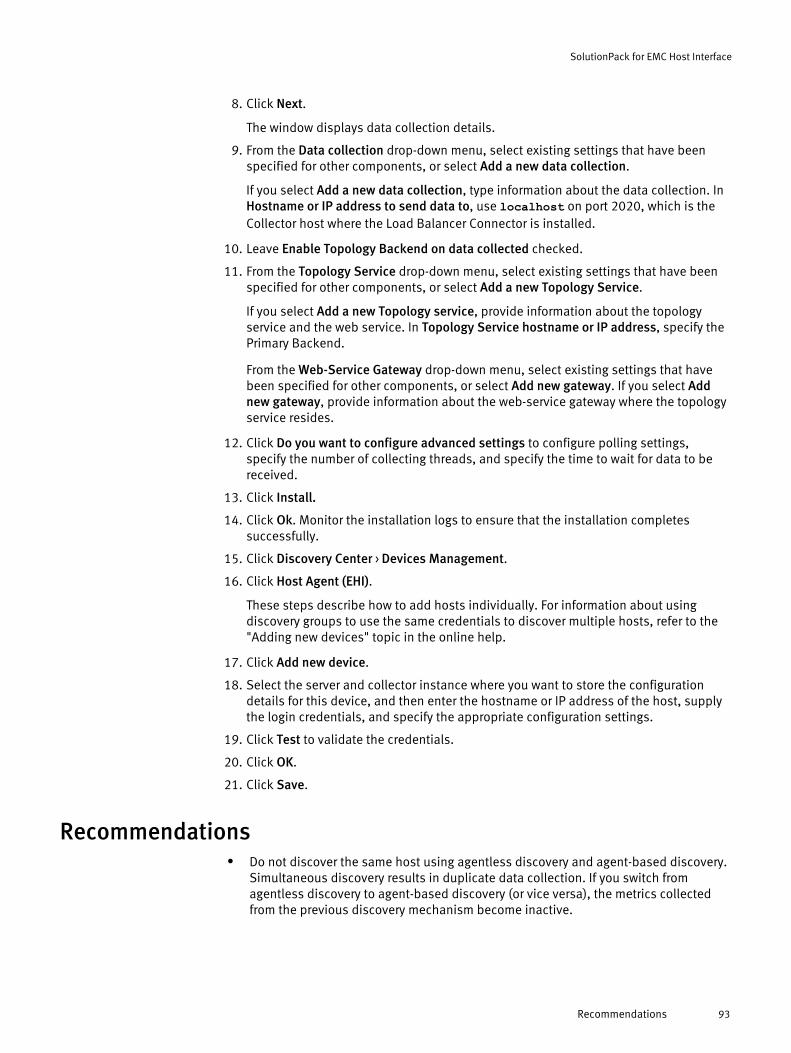
8. Click Next.
The window displays data collection details.
9. From the Data collection drop-down menu, select existing settings that have beenspecified for other components, or select Add a new data collection.
If you select Add a new data collection, type information about the data collection. InHostname or IP address to send data to, use localhost on port 2020, which is theCollector host where the Load Balancer Connector is installed.
10. Leave Enable Topology Backend on data collected checked.
11. From the Topology Service drop-down menu, select existing settings that have beenspecified for other components, or select Add a new Topology Service.
If you select Add a new Topology service, provide information about the topologyservice and the web service. In Topology Service hostname or IP address, specify thePrimary Backend.
From the Web-Service Gateway drop-down menu, select existing settings that havebeen specified for other components, or select Add new gateway. If you select Addnew gateway, provide information about the web-service gateway where the topologyservice resides.
12. Click Do you want to configure advanced settings to configure polling settings,specify the number of collecting threads, and specify the time to wait for data to bereceived.
13. Click Install.
14. Click Ok. Monitor the installation logs to ensure that the installation completessuccessfully.
15. Click Discovery Center > Devices Management.
16. Click Host Agent (EHI).
These steps describe how to add hosts individually. For information about usingdiscovery groups to use the same credentials to discover multiple hosts, refer to the"Adding new devices" topic in the online help.
17. Click Add new device.
18. Select the server and collector instance where you want to store the configurationdetails for this device, and then enter the hostname or IP address of the host, supplythe login credentials, and specify the appropriate configuration settings.
19. Click Test to validate the credentials.
20. Click OK.
21. Click Save.
Recommendationsl Do not discover the same host using agentless discovery and agent-based discovery.
Simultaneous discovery results in duplicate data collection. If you switch fromagentless discovery to agent-based discovery (or vice versa), the metrics collectedfrom the previous discovery mechanism become inactive.
SolutionPack for EMC Host Interface
Recommendations 93

Limitationsl If you add or remove a LUN and this information is not reflected on reports, you must
manually restart the EHI Agent on the host.
SolutionPack for EMC Host Interface
94 EMC ViPR SRM 3.7 SolutionPack Installation and Configuration Guide
CHAPTER 13
SolutionPack for EMC Isilon
l Overview............................................................................................................... 96l Installing the SolutionPack....................................................................................97l Updating SolutionPack alert definitions................................................................ 98l Limitations............................................................................................................98
SolutionPack for EMC Isilon 95

OverviewThe SolutionPack for EMC Isilon optimizes service availability for the EMC Isilon scale-outNAS storage solution and displays the data in easy-to-use reports within ViPR SRM.
This SolutionPack enables you to see and understand performance and utilization acrossEMC Isilon devices in real-time, to know which node is the bottleneck in a cluster, whatthe peak/busy hours are, and more.
Main reports
All cluster sizes
HDD Free, HDD Used, SSD Free, SSD Used capacities for all clusters
Clusters CPU Usage (%)
Average CPU utilization per cluster
Clusters Throughput
Inbound and outbound file system throughput across all clusters
Cluster Size
HDD Free, HDD Used, SSD Free, SSD Used capacities
Cluster Throughput
Inbound and outbound filesystem throughput
CPU Usage (%)
Average CPU utilization
Connected Connection per Protocol/Node
Maximum connected connections for CIFS, FTP, HDFS, HTTP, iSCSI, NFS, PAPI, SIQ
Active Connection per Protocol/Node
Maximum active connections for CIFS, FTP, HDFS, HTTP, iSCSI, NFS, PAPI, SIQ
Node Pools & Tiers
Free, Used, Size, Time to full, Will reach 90% on, and Utilization for pools and tiers
OneFS
Free, Used, Size, and Utilization (%)
Node Details
Node Size, Node Throughput, Node CPU Usage (%), File Systems, Bays, Interfaces
Shares
# NFS export, # CIFS share counts
More reports
Snapshot Summary, Quota Usage, Protocols performance
Supported collection interfacesFor information about supported collection interfaces, refer to the ViPR SRM SupportMatrix.
SolutionPack for EMC Isilon
96 EMC ViPR SRM 3.7 SolutionPack Installation and Configuration Guide
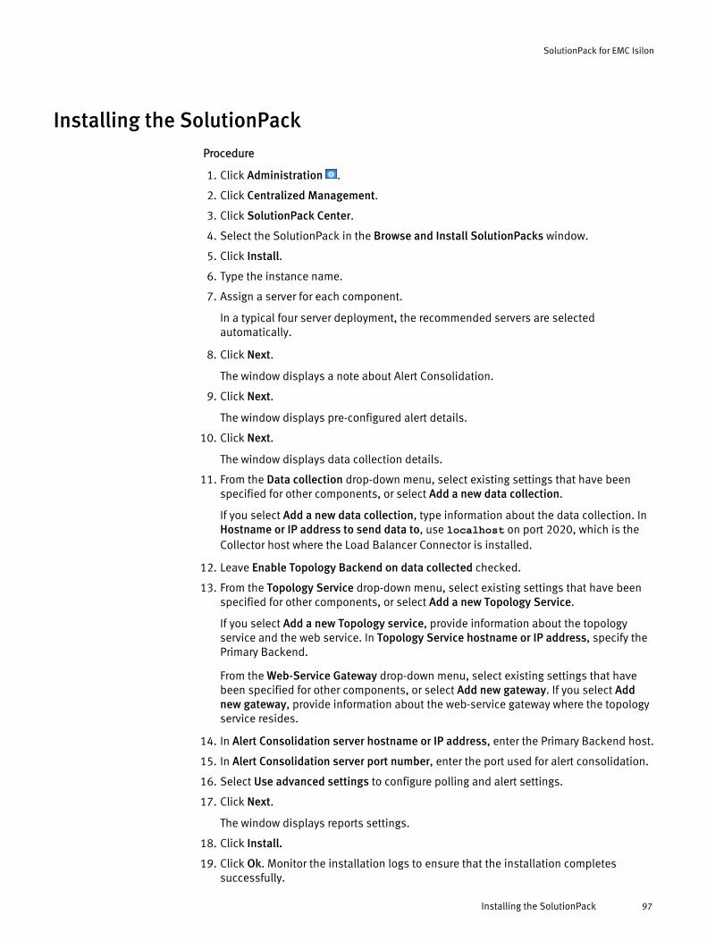
Installing the SolutionPackProcedure
1. Click Administration .
2. Click Centralized Management.
3. Click SolutionPack Center.
4. Select the SolutionPack in the Browse and Install SolutionPacks window.
5. Click Install.
6. Type the instance name.
7. Assign a server for each component.
In a typical four server deployment, the recommended servers are selectedautomatically.
8. Click Next.
The window displays a note about Alert Consolidation.
9. Click Next.
The window displays pre-configured alert details.
10. Click Next.
The window displays data collection details.
11. From the Data collection drop-down menu, select existing settings that have beenspecified for other components, or select Add a new data collection.
If you select Add a new data collection, type information about the data collection. InHostname or IP address to send data to, use localhost on port 2020, which is theCollector host where the Load Balancer Connector is installed.
12. Leave Enable Topology Backend on data collected checked.
13. From the Topology Service drop-down menu, select existing settings that have beenspecified for other components, or select Add a new Topology Service.
If you select Add a new Topology service, provide information about the topologyservice and the web service. In Topology Service hostname or IP address, specify thePrimary Backend.
From the Web-Service Gateway drop-down menu, select existing settings that havebeen specified for other components, or select Add new gateway. If you select Addnew gateway, provide information about the web-service gateway where the topologyservice resides.
14. In Alert Consolidation server hostname or IP address, enter the Primary Backend host.
15. In Alert Consolidation server port number, enter the port used for alert consolidation.
16. Select Use advanced settings to configure polling and alert settings.
17. Click Next.
The window displays reports settings.
18. Click Install.
19. Click Ok. Monitor the installation logs to ensure that the installation completessuccessfully.
SolutionPack for EMC Isilon
Installing the SolutionPack 97
20. Click Discovery Center > Devices Management.
21. Click EMC Isilon.
These steps describe how to add hosts individually. For information about usingdiscovery groups to use the same credentials to discover multiple hosts, see Addingdevices to discovery groups on page 274.
22. Click Add New Device.
23. In the Cluster hostname or IP address field, type the hostname or IP address of theSmartConnect service, or of any node in the cluster.
24. Type the username (default is admin).
25. Type the password.
26. Click Test to validate the credentials.
27. Click Ok.
28. Click Save.
Updating SolutionPack alert definitionsWhen you update a SolutionPack, any modified alert definitions supported in theupdated version are not updated by default. This is expected behavior.
To update all of the alerts:
Procedure
1. In the Alerting Frontend, navigate to Local Manager > Alert definitions > <SolutionPackName> definitions.
2. Highlight <SolutionPack Name> definitions, and click the Export icon to create abackup of the old alerts.
3. Delete all of the non-custom alerts below the <SolutionPack Name> definitions node.
4. In Centralized Management, navigate to SolutionPacks > Storage > <SolutionPackName> in the tree.
5. In the table, click the Reconfigure icon in the Pre-configured alerts row.
6. Click Reconfigure.
7. In the Alerting Frontend, navigate to Local Manager > Alert definitions > <SolutionPackName> definitions to see the updated alert definitions.
LimitationsIsilon RestAPI has a limitation that it cannot get StoragePool information for OneFS 7.0.So the Isilon SolutionPack cannot show any StoragePool information on OneFS 7.0.StoragePool information is only available for OneFS 7.1 and above.
SolutionPack for EMC Isilon
98 EMC ViPR SRM 3.7 SolutionPack Installation and Configuration Guide
CHAPTER 14
SolutionPack for EMC M&R Health
l Overview............................................................................................................. 100l Installing the SolutionPack..................................................................................100
SolutionPack for EMC M&R Health 99
OverviewThis SolutionPack monitors the health of your EMC M&R infrastructure. Take advantage ofthis no-charge SolutionPack to keep the EMC M&R services performing optimally, so youhave instant access to performance data and reports when you need it.
Supported systemsEMC M&R 6.4 and later
Data collection methodsJMX
Main reportsModules Performance
Collecting Level Performance
Backend & Databases events and utilization
Server summary
Installing the SolutionPackInstall this SolutionPack on all core software hosts in your environment.
Before you begin
l Core modules must be up-to-date in all servers because not all module dependenciesare validated during the SolutionPack installation or update process.
Procedure
1. Click Administration .
2. Click Centralized Management.
3. Click SolutionPack Center.
4. Select the SolutionPack in the Browse and Install SolutionPacks window.
5. Click Install.
6. Type the instance name.
7. Assign a server for each component.
In a typical four server deployment, the recommended servers are selectedautomatically.
8. Click Next.
The window displays pre-configured alert details.
9. Click Next.
The window displays data collection details.
10. From the Data collection drop-down menu, select existing settings that have beenspecified for other components, or select Add a new data collection.
If you select Add a new data collection, type information about the data collection. InHostname or IP address to send data to, use localhost on port 2020, which is theCollector host where the Load Balancer Connector is installed.
SolutionPack for EMC M&R Health
100 EMC ViPR SRM 3.7 SolutionPack Installation and Configuration Guide

11. From the Alerting on data collection drop-down menu, select existing settings thathave been specified for other components, or select Add a new alerting datacollection.
If you select Add a new alerting on data collection, type information about the alertingconfiguration. In Alerting Backend hostname or IP address, specify the PrimaryBackend host.
12. Select Configure advanced settings to configure polling settings.
13. Click Next.
The window displays reports settings.
14. Click Install.
15. Click Ok once installation is complete.
Performance data will displayed in about an hour.The following message might appear in the collection log during operation: WARNING-- [2014-04-25 05:26:38 EDT] -- f::a(): JVM IO ERROR 'No such process'. ID: '17032',NAME: 'lib/module-manager.jar exit'. You can ignore this message.
SolutionPack for EMC M&R Health
Installing the SolutionPack 101

SolutionPack for EMC M&R Health
102 EMC ViPR SRM 3.7 SolutionPack Installation and Configuration Guide
CHAPTER 15
SolutionPack for EMC Recoverpoint
l Overview............................................................................................................. 104l Installing the SolutionPack..................................................................................104
SolutionPack for EMC Recoverpoint 103
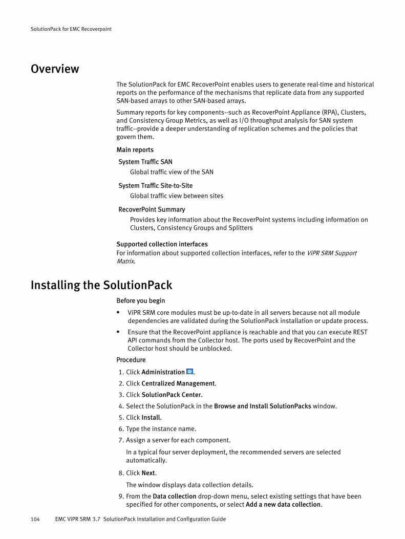
OverviewThe SolutionPack for EMC RecoverPoint enables users to generate real-time and historicalreports on the performance of the mechanisms that replicate data from any supportedSAN-based arrays to other SAN-based arrays.
Summary reports for key components--such as RecoverPoint Appliance (RPA), Clusters,and Consistency Group Metrics, as well as I/O throughput analysis for SAN systemtraffic--provide a deeper understanding of replication schemes and the policies thatgovern them.
Main reports
System Traffic SAN
Global traffic view of the SAN
System Traffic Site-to-Site
Global traffic view between sites
RecoverPoint Summary
Provides key information about the RecoverPoint systems including information onClusters, Consistency Groups and Splitters
Supported collection interfacesFor information about supported collection interfaces, refer to the ViPR SRM SupportMatrix.
Installing the SolutionPackBefore you begin
l ViPR SRM core modules must be up-to-date in all servers because not all moduledependencies are validated during the SolutionPack installation or update process.
l Ensure that the RecoverPoint appliance is reachable and that you can execute RESTAPI commands from the Collector host. The ports used by RecoverPoint and theCollector host should be unblocked.
Procedure
1. Click Administration .
2. Click Centralized Management.
3. Click SolutionPack Center.
4. Select the SolutionPack in the Browse and Install SolutionPacks window.
5. Click Install.
6. Type the instance name.
7. Assign a server for each component.
In a typical four server deployment, the recommended servers are selectedautomatically.
8. Click Next.
The window displays data collection details.
9. From the Data collection drop-down menu, select existing settings that have beenspecified for other components, or select Add a new data collection.
SolutionPack for EMC Recoverpoint
104 EMC ViPR SRM 3.7 SolutionPack Installation and Configuration Guide
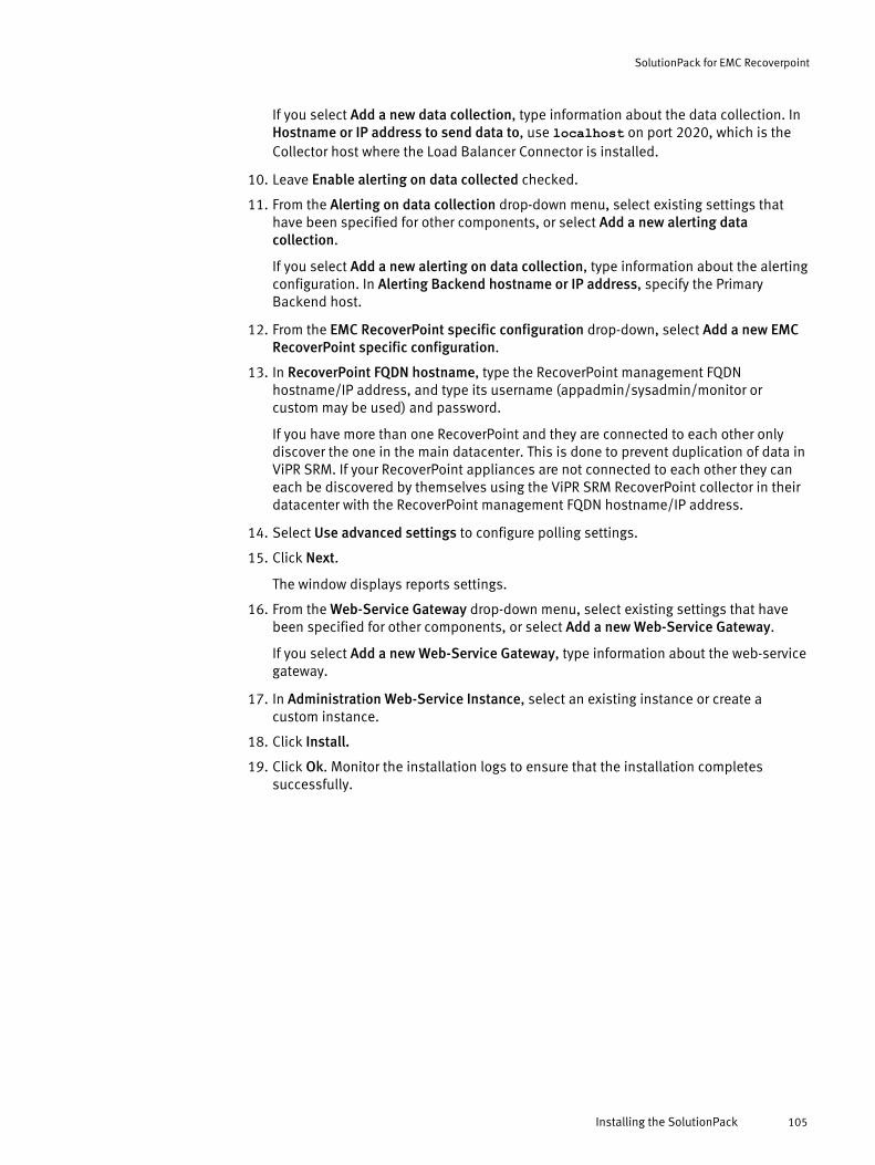
If you select Add a new data collection, type information about the data collection. InHostname or IP address to send data to, use localhost on port 2020, which is theCollector host where the Load Balancer Connector is installed.
10. Leave Enable alerting on data collected checked.
11. From the Alerting on data collection drop-down menu, select existing settings thathave been specified for other components, or select Add a new alerting datacollection.
If you select Add a new alerting on data collection, type information about the alertingconfiguration. In Alerting Backend hostname or IP address, specify the PrimaryBackend host.
12. From the EMC RecoverPoint specific configuration drop-down, select Add a new EMCRecoverPoint specific configuration.
13. In RecoverPoint FQDN hostname, type the RecoverPoint management FQDNhostname/IP address, and type its username (appadmin/sysadmin/monitor orcustom may be used) and password.
If you have more than one RecoverPoint and they are connected to each other onlydiscover the one in the main datacenter. This is done to prevent duplication of data inViPR SRM. If your RecoverPoint appliances are not connected to each other they caneach be discovered by themselves using the ViPR SRM RecoverPoint collector in theirdatacenter with the RecoverPoint management FQDN hostname/IP address.
14. Select Use advanced settings to configure polling settings.
15. Click Next.
The window displays reports settings.
16. From the Web-Service Gateway drop-down menu, select existing settings that havebeen specified for other components, or select Add a new Web-Service Gateway.
If you select Add a new Web-Service Gateway, type information about the web-servicegateway.
17. In Administration Web-Service Instance, select an existing instance or create acustom instance.
18. Click Install.
19. Click Ok. Monitor the installation logs to ensure that the installation completessuccessfully.
SolutionPack for EMC Recoverpoint
Installing the SolutionPack 105

SolutionPack for EMC Recoverpoint
106 EMC ViPR SRM 3.7 SolutionPack Installation and Configuration Guide
CHAPTER 16
SolutionPack for EMC ViPR Controller
l Overview............................................................................................................. 108l Installing the SolutionPack for EMC ViPR Controller............................................. 109
SolutionPack for EMC ViPR Controller 107

OverviewThe SolutionPack for EMC ViPR Controller provides a global view of the underlying EMCViPR Controller host and disk infrastructure, and detailed insight into ViPR-defined virtualdata centers, including the projects, tenants, virtual arrays, and virtual pools.
Main reports
Summary
Lists virtual data center names, IP addresses, and number of virtual arrays, virtualpools, hosts, block volumes, and file systems associated with each virtual datacenter. Click a row to drill into capacity summaries, an inventory list of allcomponents, and a detailed view of capacity available to each virtual array.
Storage Capacity
Raw Capacity, Usable Capacity, Usable Capacity Trends
A set of graphs showing daily capacity values.
Capacity Available to Virtual Arrays
Lists subscribed, used, and free capacity, plus percentages for subscribed andused amounts, for each virtual array/virtual pool combination.
Operations
Health Dashboard
A set of reports showing ViPR Controller health, including:
l Availability is a visual dashboard of availability percentages for each virtualdata center. Click a percentage to see a historical trend chart.
l ViPR Nodes shows host name and IP address for each node, along with %availability, % memory usage, system load averages, and disk partitionusage.
l Virtual data centers shows availability in addition to committed SLAcompared to current and probable SLA.
Performance
A set of reports showing number of read and write requests, bandwidth usagerates for read and write requests, and descriptive details for:
l File systems
l Block volumes
l Storage systems
l Virtual data center
l Virtual pools
Situations to Watch/Tenants Near Quota
Shows metrics about tenants whose %Usage is over configured thresholds andnumber of days until quota. Click a row to drill into details about the tenant.
SolutionPack for EMC ViPR Controller
108 EMC ViPR SRM 3.7 SolutionPack Installation and Configuration Guide
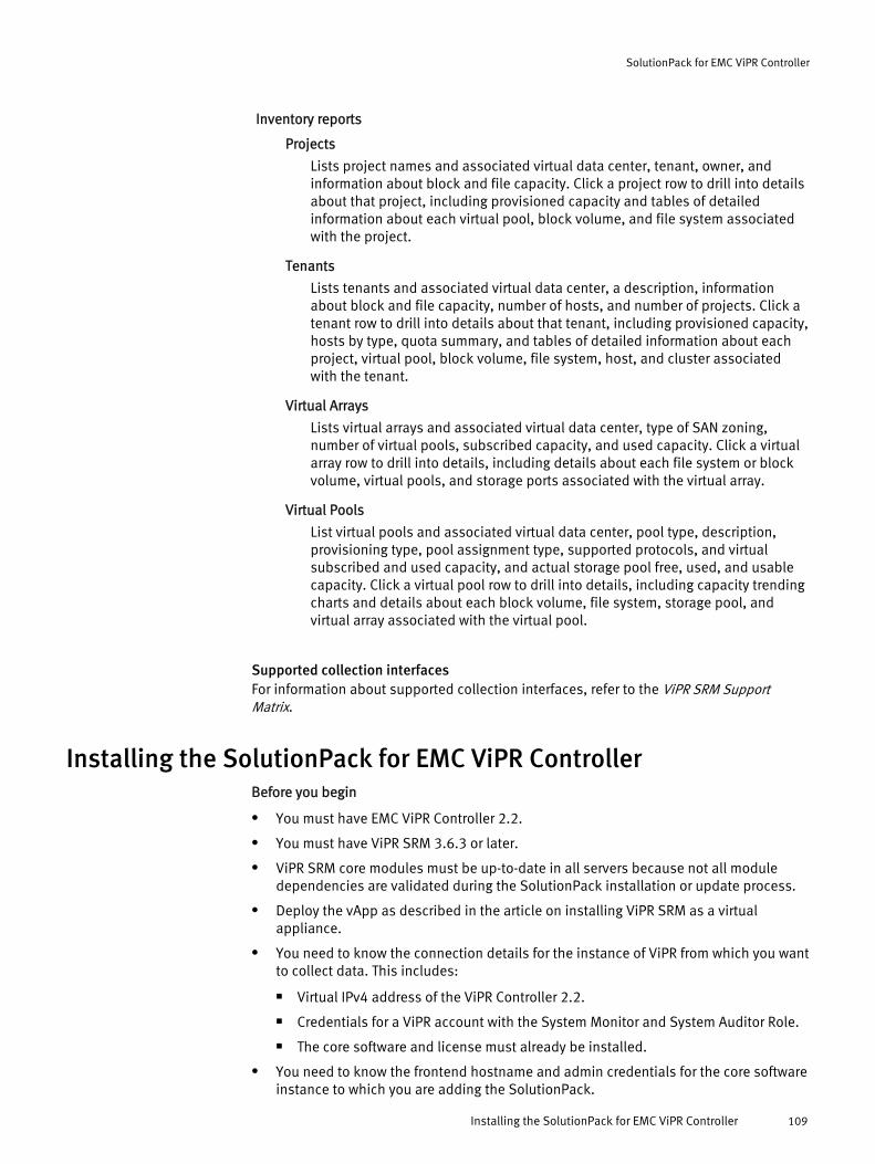
Inventory reports
Projects
Lists project names and associated virtual data center, tenant, owner, andinformation about block and file capacity. Click a project row to drill into detailsabout that project, including provisioned capacity and tables of detailedinformation about each virtual pool, block volume, and file system associatedwith the project.
Tenants
Lists tenants and associated virtual data center, a description, informationabout block and file capacity, number of hosts, and number of projects. Click atenant row to drill into details about that tenant, including provisioned capacity,hosts by type, quota summary, and tables of detailed information about eachproject, virtual pool, block volume, file system, host, and cluster associatedwith the tenant.
Virtual Arrays
Lists virtual arrays and associated virtual data center, type of SAN zoning,number of virtual pools, subscribed capacity, and used capacity. Click a virtualarray row to drill into details, including details about each file system or blockvolume, virtual pools, and storage ports associated with the virtual array.
Virtual Pools
List virtual pools and associated virtual data center, pool type, description,provisioning type, pool assignment type, supported protocols, and virtualsubscribed and used capacity, and actual storage pool free, used, and usablecapacity. Click a virtual pool row to drill into details, including capacity trendingcharts and details about each block volume, file system, storage pool, andvirtual array associated with the virtual pool.
Supported collection interfacesFor information about supported collection interfaces, refer to the ViPR SRM SupportMatrix.
Installing the SolutionPack for EMC ViPR ControllerBefore you begin
l You must have EMC ViPR Controller 2.2.
l You must have ViPR SRM 3.6.3 or later.
l ViPR SRM core modules must be up-to-date in all servers because not all moduledependencies are validated during the SolutionPack installation or update process.
l Deploy the vApp as described in the article on installing ViPR SRM as a virtualappliance.
l You need to know the connection details for the instance of ViPR from which you wantto collect data. This includes:
n Virtual IPv4 address of the ViPR Controller 2.2.
n Credentials for a ViPR account with the System Monitor and System Auditor Role.
n The core software and license must already be installed.
l You need to know the frontend hostname and admin credentials for the core softwareinstance to which you are adding the SolutionPack.
SolutionPack for EMC ViPR Controller
Installing the SolutionPack for EMC ViPR Controller 109

Procedure
1. Click Administration .
2. Click Centralized Management.
3. Click SolutionPack Center.
4. Select the SolutionPack in the Browse and Install SolutionPacks window.
5. Click Install.
6. Type the instance name.
7. Assign a server for each component.
In a typical four server deployment, the recommended servers are selectedautomatically.
8. Click Next.
The window displays a note about Alert Consolidation.
9. Click Next.
The window displays pre-configured alert details.
10. From the Alerting on data collection drop-down menu, select the Primary Backendhost.
11. Click Next.
The window displays data collection details.
12. From the Data collection drop-down menu, select existing settings that have beenspecified for other components, or select Add a new data collection.
If you select Add a new data collection, type information about the data collection. InHostname or IP address to send data to, use localhost on port 2020, which is theCollector host where the Load Balancer Connector is installed.
13. From the Alert Consolidation drop-down menu, select existing settings that have beenspecified for other components, or select Add a new Alert consolidation.
If you select Add a new Alert consolidation, type information about the alertingconfiguration. In Alerting Backend hostname or IP address, specify the PrimaryBackend host.
14. From the Frontend Web service drop-down menu, select existing settings that havebeen specified for other components, or select Add a new Frontend Web service.
If you select Add a new Frontend Web service, type information about the FrontendWeb service.
15. Leave Enable Topology Backend on data collected checked.
16. From the Topology Service drop-down menu, select existing settings that have beenspecified for other components, or select Add a new Topology Service.
If you select Add a new Topology service, provide information about the topologyservice and the web service. In Topology Service hostname or IP address, specify thePrimary Backend.
From the Web-Service Gateway drop-down menu, select existing settings that havebeen specified for other components, or select Add new gateway. If you select Addnew gateway, provide information about the web-service gateway where the topologyservice resides.
17. Select Use advanced settings to configure polling settings or to disable a polling type.
SolutionPack for EMC ViPR Controller
110 EMC ViPR SRM 3.7 SolutionPack Installation and Configuration Guide

18. In each polling period drop-down menu, select a polling period or select Disabled toturn off the polling.
19. Click Next.
The window displays reports settings.
20. In Administration Web-Service Instance, select an existing instance or create acustom instance.
21. Click Install.
22. Click Ok. Monitor the installation logs to ensure that the installation completessuccessfully.
23. Click Discovery Center > Devices Management.
24. Click ViPR.
25. Click Add new device.
26. In Server, select the ViPR Collector.
27. In Instance, select the ViPR instance.
28. For each ViPR Controller server from which you want to collect data, enter a uniquename, its public virtual IPv4 address, and credentials for an account with the SystemAdministrator role.
29. Click Test to validate the credentials.
30. Click Ok, and then Save.
SolutionPack for EMC ViPR Controller
Installing the SolutionPack for EMC ViPR Controller 111

SolutionPack for EMC ViPR Controller
112 EMC ViPR SRM 3.7 SolutionPack Installation and Configuration Guide

CHAPTER 17
SolutionPack for EMC VMAX
l Overview............................................................................................................. 114l Configuring the access credentials...................................................................... 115l Preparing EMC VMAX for discovery and data collection .......................................115l Installing the SolutionPack..................................................................................121l Troubleshooting Discovery Center connectivity failures....................................... 124l Updating SolutionPack alert definitions.............................................................. 127l Configuring Solutions Enabler client access for VMAX......................................... 128l Resolving SMI-S Provider port conflicts................................................................132l Limitations..........................................................................................................132
SolutionPack for EMC VMAX 113

OverviewThe SolutionPack for EMC VMAX reports Input/Output Operations Per Second (IOPS) onDisks, directors, and devices to measure performance and assure service availability.Alerts are consolidated from EMC VMAX and shown on the All Alerts Console.
Main reports
Storage Pool Capacity Planning
Trending and forecasting capacity for all arrays and pools, giving expected capacitybased on trend
Thin Devices
Trending and forecasting capacity for all Thin Devices, giving bound devices capacityand the total Thin Devices consumed
Tiers
Trending and forecasting capacity for all arrays and tiers, giving expected capacitybased on trend
All disks
Table listing information from all of the disks, including it's array, name, type, groupRPM, director, IOPS, throughput and capacity
By DiskGroup
Table listing information from all of the disk groups, including it's array, disk groupname, director, raw capacity, hyper capacity, free capacity and usage percentage
Masking views Summary
Capacity as seen by hosts in the masking view
Pool Capacity
Capacity information for all of the Pools available, including array, pool name, poolstate and capacity used
Configured Usable
Trending and forecasting on the sum of all thick devices (including standard, BCVand R1 devices) plus the sum of all data devices (pool storage)
Hot Spares
Trending and forecasting on the sum of disks dedicated as hot spares
RAID overhead
Report on the array capacity used to support RAID protection overhead
Unconfigured
Report on all thick devices plus the sum of all data devices (pool storage)
Array ID
Overview of all VMAX main components, physical and logical
Arrays
Lists all the VMAX systems
Disks
Lists all disks and related key information, for all arrays
SolutionPack for EMC VMAX
114 EMC ViPR SRM 3.7 SolutionPack Installation and Configuration Guide
Directors
Lists all directors and related key information, for all arrays
Ports
Lists all ports and status for all arrays
Pools
Lists all pools and related key information, for all array.
Storage Groups
Lists all Storage Groups and related key information
Ports
Lists all ports and status for all arrays
Devices
Lists all devices and related key information, for all arrays
Storage Groups Summary
Performance and capacity of all storage groups for this array, including IO Densityand Response Time
FE|BE|RDF Directors
Key performance metrics for all directors and ports
Supported collection interfacesFor information about supported collection interfaces, refer to the ViPR SRM SupportMatrix.
Configuring the access credentialsM&R uses different accounts when running SolutionPacks.
SMI-S Provider default credentials are provided during SolutionPack installation:
l Username - the default is adminl Password - the default is #1PasswordUnisphere for VMAX credentials:
l Username - the default is smcl Password - the default is smc
Preparing EMC VMAX for discovery and data collectionIdentify the information required to support data collection before installing theSolutionPack for EMC VMAX and perform the necessary pre-configuration.
VMAX3 discovery scenario
Array Provider HostVMAX3 arrays are collected using the VMAX SMI-S Provider and optionally Unisphere forVMAX. The SMI-S Provider is used to collect capacity, topology, basic performance data,and LUN performance data. Unisphere for VMAX can be used to collect the basicperformance data as well as several additional performance data, but it cannot collect
SolutionPack for EMC VMAX
Configuring the access credentials 115

LUN performance data. Therefore, the VMAX collector should be configured to use boththe SMI-S Provider and Unisphere for VMAX so that all VMAX report fields will have data.It is recommended that both the SMI-S Provider and Unisphere for VMAX are installed tothe same Array Provider Host. This Array Provider Host should have six or more dedicatedgatekeepers for each VMAX array that is connected to it.
"Remote Discovery Configuration" is referred to when SMI-S Provider and Unisphere areinstalled on an Array Provider Host which is separate from the VMAX Collector Host. Theminimum Array Provider Host configuration is 4 CPUs and 16 GB memory. More memorywill be required when managing more than 50k total devices, with a maximum of 100kdevices per Array Provider Host. Refer to the Unisphere for VMAX Release Notes todetermine the Array Provider Host's scalability and CPU/Memory requirements.
The SMI-S Provider and Unisphere for VMAX can be installed on the ViPR SRM CollectorHost (this is referred to as "Local Discovery Configuration"). Local Discovery Configurationrequires a minimum of 4 to 8 CPUs and 32GB memory to support the VMAX Collector aswell as the SMI-S Provider and Unisphere for VMAX. Sufficient memory and CPU must beprovided on the Collector Host to support all of these components as well as any otherhosted collectors or processes.
Unisphere for VMAX and the SMI-S Provider will gather performance data for arrays thatare directly SAN-attached to the Array Provider Host (called a "Local connection" to thearray). Performance data is not available for arrays that are indirectly attached to theArray Provider Host through another array's SRDF connection (called a "Remoteconnection" to the array). Arrays must be registered in the Unisphere for VMAXPerformance UI to provide performance data. Once performance data is available inUnisphere/SMI-S and the array is collected, it may take 2 to 3 hours before theperformance data will be seen in the VMAX reports.
Collector Host (Remote Discovery Configuration)Collector Hosts are installed with the SolutionPack for VMAX and configured to connect tothe SMI-S Provider and Unisphere for VMAX on the Array Provider Host. Refer to the ViPRSRM Performance & Scalability Guidelines for SolutionPack for VMAX planning based uponthe number of arrays and array configurations being managed. As a rule, ViPR SRMCollector Hosts should be installed as near as possible to the Array Provider Host to avoidnetwork latency between the collector and SMI-S Provider and Unisphere. For example, ifthere is high network latency (100 ms or greater) from the local datacenter to the remotedatacenter then the VMAX Collector Host and Array Provider Host should be co-locatedwithin the remote datacenter.
Verifying the configurationVerify the VMAX collector configuration is correct by using the Discovery Center Testoption for each VMAX array. Tests performed include basic SMI-S/Unisphere connectivitytests, SMI-S/Unisphere version checks, and an array existence test. The configureddiscovery settings can be confirmed by using the Test utility as described in Troubleshooting Discovery Center connectivity failures on page 124. Alternately, the SMI-S TestSmiProvider utility's dv command can be used to confirm the software versionand connected arrays on the Array Provider Host.
# cd /opt/emc/ECIM/ECOM/bin or ?:\Program Files\EMC\ECIM\ECOM\bin#./TestSmiProvider or TestSmiProvider.exeSolutionPack for EMC VMAXConfiguring the access credentials 103Connection Type (ssl,no_ssl,native) [no_ssl]:Host [localhost]:Port [5988]:Username [admin]:Password [#1Password]:Log output to console [y|n (default y)]:
SolutionPack for EMC VMAX
116 EMC ViPR SRM 3.7 SolutionPack Installation and Configuration Guide
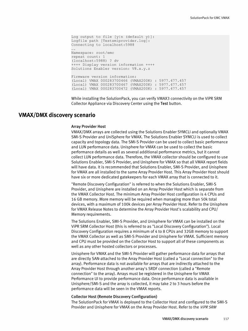
Log output to file [y|n (default y)]:Logfile path [Testsmiprovider.log]:Connecting to localhost:5988….Namespace: root/emcrepeat count: 1(localhost:5988) ? dv++++ Display version information ++++Solutions Enabler version: V8.x.y.z
Firmware version information:(Local) VMAX 000283700466 (VMAX200K) : 5977.477.457(Local) VMAX 000283700467 (VMAX200K) : 5977.477.457(Local) VMAX 000283700472 (VMAX200K) : 5977.477.457
While installing the SolutionPack, you can verify VMAX3 connectivity on the ViPR SRMCollector Appliance via Discovery Center using the Test button.
VMAX/DMX discovery scenario
Array Provider HostVMAX/DMX arrays are collected using the Solutions Enabler SYMCLI and optionally VMAXSMI-S Provider and UniSphere for VMAX. The Solutions Enabler SYMCLI is used to collectcapacity and topology data. The SMI-S Provider can be used to collect basic performanceand LUN performance data. Unisphere for VMAX can be used to collect the basicperformance details as well as several additional performance metrics, but it cannotcollect LUN performance data. Therefore, the VMAX collector should be configured to useSolutions Enabler, SMI-S Provider, and Unisphere for VMAX so that all VMAX report fieldswill have data. It is recommended that Solutions Enabler, SMI-S Provider, and Unispherefor VMAX are all installed to the same Array Provider Host. This Array Provider Host shouldhave six or more dedicated gatekeepers for each VMAX array that is connected to it.
"Remote Discovery Configuration" is referred to when the Solutions Enabler, SMI-SProvider, and Unisphere are installed on an Array Provider Host which is separate fromthe VMAX Collector Host. The minimum Array Provider Host configuration is 4 CPUs and16 GB memory. More memory will be required when managing more than 50k totaldevices, with a maximum of 100k devices per Array Provider Host. Refer to the Unispherefor VMAX Release Notes to determine the Array Provider Host's scalability and CPU/Memory requirements.
The Solutions Enabler, SMI-S Provider, and Unisphere for VMAX can be installed on theViPR SRM Collector Host (this is referred to as "Local Discovery Configuration"). LocalDiscovery Configuration requires a minimum of 4 to 8 CPUs and 32GB memory to supportthe VMAX Collector as well as SMI-S Provider and Unisphere for VMAX. Sufficient memoryand CPU must be provided on the Collector Host to support all of these components aswell as any other hosted collectors or processes.
Unisphere for VMAX and the SMI-S Provider will gather performance data for arrays thatare directly SAN-attached to the Array Provider Host (called a "Local connection" to thearray). Performance data is not available for arrays that are indirectly attached to theArray Provider Host through another array's SRDF connection (called a "Remoteconnection" to the array). Arrays must be registered in the Unisphere for VMAXPerformance UI to provide performance data. Once performance data is available inUnisphere/SMI-S and the array is collected, it may take 2 to 3 hours before theperformance data will be seen in the VMAX reports.
Collector Host (Remote Discovery Configuration)The SolutionPack for VMAX is deployed to the Collector Host and configured to the SMI-SProvider and Unisphere for VMAX on the Array Provider Host. Refer to the ViPR SRM
SolutionPack for EMC VMAX
VMAX/DMX discovery scenario 117

Performance & Scalability Guidelines for SolutionPack for VMAX planning based upon thenumber of arrays and array configurations being managed. As a rule, ViPR SRM CollectorHosts should be installed as near as possible to the Array Provider Host to avoid networklatency between the collector and SMI-S Provider and Unisphere. For example, if there ishigh network latency (100 ms or greater) from the local datacenter to the remotedatacenter then the VMAX Collector Host and Array Provider Host should be collocatedwithin the remote datacenter.
Verifying the configurationVerify the VMAX collector configuration is correct by using the Discovery Center Testoption for each VMAX array. Tests performed include basic SYMCLI/SMI-S/Unisphereconnectivity tests, SYMCLI/SMI-S/Unisphere version checks, and an array existence test.The configured discovery settings can be confirmed by using the Test utility as describedin Troubleshooting Discovery Center connectivity failures on page 124. Alternately, theSYMCLI symcfg list -v and SMI-S TestSmiProvider utility's dv command canbe used to confirm the software version and connected arrays on the Array Provider Host.
Creating VMAX3/VMAX collectors for discovery of Symmetrix arrays (local discoveryconfiguration)
The following procedure describes how to create VMAX collectors for discovery ofSymmetrix arrays in ViPR SRM.
Procedure
1. Create a Windows (2008, 2012, 2012R2) or Linux (RH 5+, Suse 10+) Vmguest with 8RDM gatekeepers allocated to the server from each local Symmetrix array (have beentested for 60,000 volumes total).
2. Size the server as follows: 4-8 CPUs, 32 GB RAM, 200 GB Storage.
3. Install Solutions Enabler with SMI-S and Unisphere for VMAX on the VMAX collectorserver. This server will only be used for ViPR SRM data collection (no productionallocation use).
4. Make sure the server can see no more than 50,000 Symmetrix volumes (64,000 forjumbo arrays) and be sure to leave room for growth. Run symcfg list from SolutionsEnabler to verify.
5. Create a symavoid file if too many Symmetrix arrays are visible until you get thevolume count on the server below 50,000 volumes (64,000 for jumbo arrays) and besure to allow for growth. You will be blocking the remote arrays as well in thesymavoid file. Remote arrays will be discovered in remote datacenters locally by aVMAX collector server there.
6. Install ViPR SRM collector software on this server. Add this server to ViPR SRM as ascale out collector.
7. Install only the VMAX SolutionPack collector on this server.
8. Set the Java heap for the VMAX collector to 8 GB (8192) (refer to the ViPR SRMPerformance and Scalability guidelines for more information).
9. In ViPR SRM, use only the local discovery option and enter the Solutions Enablerinstall directory, if it is not the default.
10. This server will be used to fill in the Unisphere for VMAX and SMI-S fields for discoveryin ViPR SRM.
SolutionPack for EMC VMAX
118 EMC ViPR SRM 3.7 SolutionPack Installation and Configuration Guide
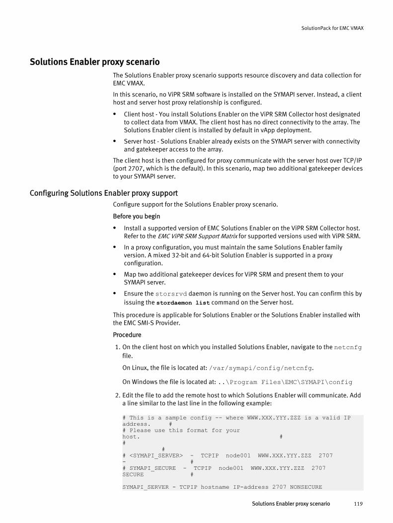
Solutions Enabler proxy scenarioThe Solutions Enabler proxy scenario supports resource discovery and data collection forEMC VMAX.
In this scenario, no ViPR SRM software is installed on the SYMAPI server. Instead, a clienthost and server host proxy relationship is configured.
l Client host - You install Solutions Enabler on the ViPR SRM Collector host designatedto collect data from VMAX. The client host has no direct connectivity to the array. TheSolutions Enabler client is installed by default in vApp deployment.
l Server host - Solutions Enabler already exists on the SYMAPI server with connectivityand gatekeeper access to the array.
The client host is then configured for proxy communicate with the server host over TCP/IP(port 2707, which is the default). In this scenario, map two additional gatekeeper devicesto your SYMAPI server.
Configuring Solutions Enabler proxy supportConfigure support for the Solutions Enabler proxy scenario.
Before you begin
l Install a supported version of EMC Solutions Enabler on the ViPR SRM Collector host.Refer to the EMC ViPR SRM Support Matrix for supported versions used with ViPR SRM.
l In a proxy configuration, you must maintain the same Solutions Enabler familyversion. A mixed 32-bit and 64-bit Solution Enabler is supported in a proxyconfiguration.
l Map two additional gatekeeper devices for ViPR SRM and present them to yourSYMAPI server.
l Ensure the storsrvd daemon is running on the Server host. You can confirm this byissuing the stordaemon list command on the Server host.
This procedure is applicable for Solutions Enabler or the Solutions Enabler installed withthe EMC SMI-S Provider.
Procedure
1. On the client host on which you installed Solutions Enabler, navigate to the netcnfgfile.
On Linux, the file is located at: /var/symapi/config/netcnfg.
On Windows the file is located at: ..\Program Files\EMC\SYMAPI\config2. Edit the file to add the remote host to which Solutions Enabler will communicate. Add
a line similar to the last line in the following example:
# This is a sample config -- where WWW.XXX.YYY.ZZZ is a valid IP address. ## Please use this format for your host. ## ## <SYMAPI_SERVER> - TCPIP node001 WWW.XXX.YYY.ZZZ 2707 - ## SYMAPI_SECURE - TCPIP node001 WWW.XXX.YYY.ZZZ 2707 SECURE # SYMAPI_SERVER - TCPIP hostname IP-address 2707 NONSECURE
SolutionPack for EMC VMAX
Solutions Enabler proxy scenario 119
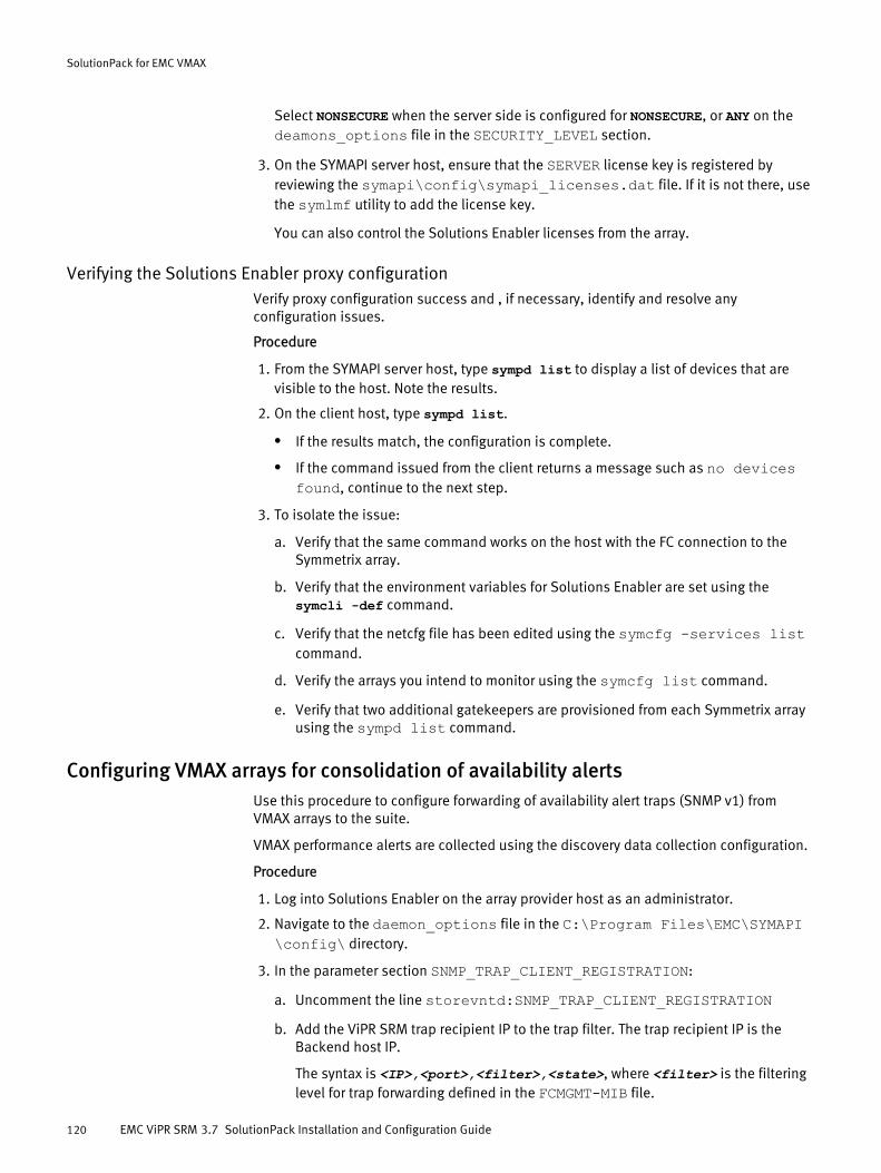
Select NONSECURE when the server side is configured for NONSECURE, or ANY on thedeamons_options file in the SECURITY_LEVEL section.
3. On the SYMAPI server host, ensure that the SERVER license key is registered byreviewing the symapi\config\symapi_licenses.dat file. If it is not there, usethe symlmf utility to add the license key.
You can also control the Solutions Enabler licenses from the array.
Verifying the Solutions Enabler proxy configurationVerify proxy configuration success and , if necessary, identify and resolve anyconfiguration issues.
Procedure
1. From the SYMAPI server host, type sympd list to display a list of devices that arevisible to the host. Note the results.
2. On the client host, type sympd list.
l If the results match, the configuration is complete.
l If the command issued from the client returns a message such as no devicesfound, continue to the next step.
3. To isolate the issue:
a. Verify that the same command works on the host with the FC connection to theSymmetrix array.
b. Verify that the environment variables for Solutions Enabler are set using thesymcli -def command.
c. Verify that the netcfg file has been edited using the symcfg -services listcommand.
d. Verify the arrays you intend to monitor using the symcfg list command.
e. Verify that two additional gatekeepers are provisioned from each Symmetrix arrayusing the sympd list command.
Configuring VMAX arrays for consolidation of availability alertsUse this procedure to configure forwarding of availability alert traps (SNMP v1) fromVMAX arrays to the suite.
VMAX performance alerts are collected using the discovery data collection configuration.
Procedure
1. Log into Solutions Enabler on the array provider host as an administrator.
2. Navigate to the daemon_options file in the C:\Program Files\EMC\SYMAPI\config\ directory.
3. In the parameter section SNMP_TRAP_CLIENT_REGISTRATION:
a. Uncomment the line storevntd:SNMP_TRAP_CLIENT_REGISTRATIONb. Add the ViPR SRM trap recipient IP to the trap filter. The trap recipient IP is the
Backend host IP.
The syntax is <IP>,<port>,<filter>,<state>, where <filter> is the filteringlevel for trap forwarding defined in the FCMGMT-MIB file.
SolutionPack for EMC VMAX
120 EMC ViPR SRM 3.7 SolutionPack Installation and Configuration Guide
Example: 10.31.90.148, 2041,10,ACTIVE4. In the parameter section LOG_EVENT_TARGETS, uncomment the linestorevntd:LOG_EVENT_TARGETS = snmp file.
5. To identify the arrays from which traps should be forwarded to the suite, type symcfglist, and press Enter.
6. For each array that should forward alert traps to ViPR SRM:
a. Type symcfg list, and press Enter.
b. In the parameter section LOG_SYMMETRIX_EVENTS, specify the appropriateevent categories in the format:
sid=<SYM serial number>, <event category 1>, <eventcategory 2>\
Example: SID=000194900854, disk, device, device pool,director, srdf consistency group, srdfa session, srdflink, srdf system, service processor, environmental,diagnostic, checksum, status, events, array subsystem,groups, optimizer, thresh_critical=3, thresh_major=2,thresh_warning=1, thresh_info=0 ;\
7. To reload the changes to the daemon_options file, type stordaemon actionstorevntd -cmd reload, and press Enter.
8. Ensure that the storevntd Event Daemon is running on the provider host.
9. If you have multiple VMAX array provider hosts in your storage environment, repeatthis procedure on each array provider host.
Installing the SolutionPackBefore you begin
l ViPR SRM core modules must be up-to-date in all servers because not all moduledependencies are validated during the SolutionPack installation or update process.
l The ViPR SRM Alerting Guide explains how to configure alerts consolidation.
Note
Data collection instances cannot collect data for both VMAX2/DMX and VMAX3 andarrays at the same time. You need to define separate instances if you plan to collect bothVMAX2/DMX and VMAX3 data. It is recommended to include "V2" or "V3" in the name ofthe instance to easily select the right instance in the Discovery Center when adding serialnumbers to collect.
Procedure
1. Click Administration .
2. Click Centralized Management.
3. Click SolutionPack Center.
4. Select the SolutionPack in the Browse and Install SolutionPacks window.
5. Click Install.
6. Type the instance name.
SolutionPack for EMC VMAX
Installing the SolutionPack 121

You cannot collect VMAX3 and VMAX2 arrays using the same instance. It is suggestedto indicate the type of VMAX in the instance name ("V2" or "V3") to ease the deviceconfiguration.
7. Assign a server for each component.
In a typical four server deployment, the recommended servers are selectedautomatically.
8. Click Next.
The window displays a note about Alert Consolidation.
9. Click Next.
The window displays pre-configured alert details.
10. Click Next.
The window displays data collection details.
11. From the Data collection drop-down menu, select existing settings that have beenspecified for other components, or select Add a new data collection.
If you select Add a new data collection, type information about the data collection. InHostname or IP address to send data to, use localhost on port 2020, which is theCollector host where the Load Balancer Connector is installed.
12. From the Frontend Web service drop-down menu, select existing settings that havebeen specified for other components, or select Add a new Frontend Web service.
If you select Add a new Frontend Web service, type information about the FrontendWeb service.
13. From the Topology Service drop-down menu, select existing settings that have beenspecified for other components, or select Add a new Topology Service.
If you select Add a new Topology service, provide information about the topologyservice and the web service. In Topology Service hostname or IP address, specify thePrimary Backend.
From the Web-Service Gateway drop-down menu, select existing settings that havebeen specified for other components, or select Add new gateway. If you select Addnew gateway, provide information about the web-service gateway where the topologyservice resides.
14. From the Type of VMAX array collected drop-down menu, select the type of VMAXarrays collected with this data collection instance.
You cannot collect VMAX3 and VMAX2 arrays using the same instance.
15. Configure the collection intervals as needed.
16. Click Next.
The window displays reports settings.
17. Click Install.
18. Click Ok when the installation is complete.
19. Click Discovery Center > Devices Management.
20. Click EMC VMAX.
21. Click Add new device.
22. In Server, select the server where the device will be dispatched.
SolutionPack for EMC VMAX
122 EMC ViPR SRM 3.7 SolutionPack Installation and Configuration Guide

23. In Instance, select the instance of the emc-vmax-collect where the device will bedispatched.
Select the same type of VMAX array as the selected SolutionPack Block instance.
24. In Array Full Serial Number, type the Symmetrix 12-digit serial number for which datawill be collected.
To view the list of arrays, enter * in place of the Array Full Serial Number and click Testor run the symcli command symcfg list.
Note
EMC recommends not to exceed six medium-sized (30K-40K devices) VMAX arrays foreach VMAX collector.
25. In Type of performance collection (excluding LUN), select the type of source forperformance metrics related to the array and its components (except LUN).
Option Description
None Do not collect performance metrics
SMI-S Collect performance metrics via SMI-S
Unisphere for VMAX Collect performance metrics via Unisphere for VMAX
26. In Type of performance collection for LUN, select the type of source for performancemetrics related to the array LUNs.
Option Description
None Do not collect LUN performance metrics
SMI-S Collect LUN performance metrics via SMI-S
27. Check Enable SRDF Groups Collection if you want to see fully populated SRDF reports.
28. If you are collecting data for VMAX2/DMX arrays, enter the following settings in theSYMCLI configuration section:
a. If Solutions Enabler was installed in the default location, leave the SolutionsEnabler bin directory empty. If Solutions Enabler was installed in another location,type the path to the bin directory.
b. In Connection type, select Remote if you are using the Solutions Enabler proxyscenario or Local if you are using a local Solutions Enabler scenario. Refer to Preparing EMC VMAX for discovery and data collection on page 115.
c. In SYMCLI Connection name, type the remote connection name. This is the nameof a SYMCLI service, which is configured in the netconfig file (netcnfg). This isnot a host name. To view the name that is configured, use the symcfg list -services command.
d. Check Use -offline mode as needed.
Enabling SYMCLI offline mode reduces CPU load on front-end directors whereSolutions Enabler gatekeeper devices are located. Use this option only if the SMI-SProvider or Unisphere for VMAX are running on the same Solutions Enabler wherethe SYMCLI commands will be executed.
SolutionPack for EMC VMAX
Installing the SolutionPack 123
29. If you are collecting data for VMAX3 arrays, or collecting performance data via SMI-S,enter the following settings in the SMI-S configuration section:
a. In SMI-S Provider/CIMOM host, type the name, FQDN, or IP address of the SMI-Sprovider host.
b. In SMI-S Provider/CIMOM port, type the port on which the SMI-S provider islistening if it is different from the default port.
c. In Username and Password, type the SMI-S credentials to use.
d. Check Enable Secure Connection (SSL) to enable SSL for all communicationsbetween the collector and the SMI-S provider.
e. In SMI-S version, select the appropriate version of the SMI-S provider.
30. If you are collecting performance data via Unisphere for VMAX, enter the followingsettings in the Unisphere for VMAX configuration section:
a. In Unisphere hostname or IP address, type the name, FQDN, or IP address of theUnisphere for VMAX host.
b. In Unisphere network port, type the port on which Unisphere for VMAX is listening.
c. In Username and Password, type the Unisphere for VMAX credentials to use.
d. In Unisphere version, select the appropriate version of Unisphere for VMAX.
e. Check Collect MAX values from Unisphere to collect additional performancemetrics (maximum values of some of the metrics usually collected).
31. Click Test to validate the credentials.
For information about connectivity test failures, refer to Troubleshooting DiscoveryCenter connectivity failures on page 124.
32. Click Ok.
33. Click Save.
Performance data will be displayed in about an hour.
Discovery of large (> 20K devices) Symmetrix arrays may take long periods of time dueto the number of volumes. To address this, discover the Symmetrix on its owninstance. This will prevent the discovery from impacting the discovery of other arrayson the same SYMAPI connection and allows the smaller arrays to complete during thepolling schedule.
Troubleshooting Discovery Center connectivity failuresDiscovery Center enables you to test connectivity between the ViPR SRM VMAX collectorand the VMAX array providers.
Viewing the Test button test resultsTest results are displayed in the Test button tool tip.
In addition to providing error and warning messages, the test results tool tip alsoprovides useful information such as: SYMCLI version, SYMAPI version, SYMAPI Run Timeversion, SYMAPI Server version, number of dedicated gate keepers per array, andSYMAUTH users.
SolutionPack for EMC VMAX
124 EMC ViPR SRM 3.7 SolutionPack Installation and Configuration Guide
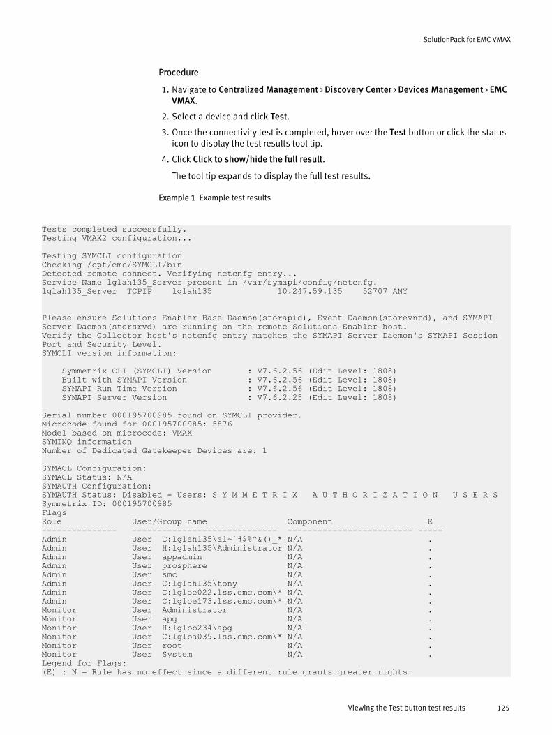
Procedure
1. Navigate to Centralized Management > Discovery Center > Devices Management > EMCVMAX.
2. Select a device and click Test.
3. Once the connectivity test is completed, hover over the Test button or click the statusicon to display the test results tool tip.
4. Click Click to show/hide the full result.
The tool tip expands to display the full test results.
Example 1 Example test results
Tests completed successfully. Testing VMAX2 configuration...
Testing SYMCLI configurationChecking /opt/emc/SYMCLI/binDetected remote connect. Verifying netcnfg entry...Service Name lglah135_Server present in /var/symapi/config/netcnfg.lglah135_Server TCPIP lglah135 10.247.59.135 52707 ANY
Please ensure Solutions Enabler Base Daemon(storapid), Event Daemon(storevntd), and SYMAPI Server Daemon(storsrvd) are running on the remote Solutions Enabler host.Verify the Collector host's netcnfg entry matches the SYMAPI Server Daemon's SYMAPI Session Port and Security Level.SYMCLI version information:
Symmetrix CLI (SYMCLI) Version : V7.6.2.56 (Edit Level: 1808) Built with SYMAPI Version : V7.6.2.56 (Edit Level: 1808) SYMAPI Run Time Version : V7.6.2.56 (Edit Level: 1808) SYMAPI Server Version : V7.6.2.25 (Edit Level: 1808)
Serial number 000195700985 found on SYMCLI provider.Microcode found for 000195700985: 5876Model based on microcode: VMAXSYMINQ informationNumber of Dedicated Gatekeeper Devices are: 1
SYMACL Configuration:SYMACL Status: N/ASYMAUTH Configuration:SYMAUTH Status: Disabled - Users: S Y M M E T R I X A U T H O R I Z A T I O N U S E R SSymmetrix ID: 000195700985FlagsRole User/Group name Component E--------------- ----------------------------- ------------------------- -----Admin User C:lglah135\a1~`#$%^&()_* N/A .Admin User H:lglah135\Administrator N/A .Admin User appadmin N/A .Admin User prosphere N/A .Admin User smc N/A .Admin User C:lglah135\tony N/A .Admin User C:lgloe022.lss.emc.com\* N/A .Admin User C:lgloe173.lss.emc.com\* N/A .Monitor User Administrator N/A .Monitor User apg N/A .Monitor User H:lglbb234\apg N/A .Monitor User C:lglba039.lss.emc.com\* N/A .Monitor User root N/A .Monitor User System N/A .Legend for Flags:(E) : N = Rule has no effect since a different rule grants greater rights.
SolutionPack for EMC VMAX
Viewing the Test button test results 125
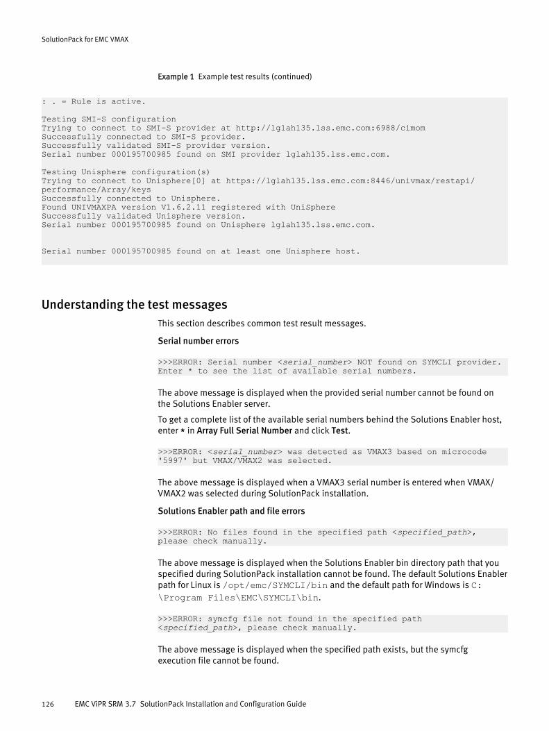
Example 1 Example test results (continued)
: . = Rule is active.
Testing SMI-S configurationTrying to connect to SMI-S provider at http://lglah135.lss.emc.com:6988/cimomSuccessfully connected to SMI-S provider.Successfully validated SMI-S provider version.Serial number 000195700985 found on SMI provider lglah135.lss.emc.com.
Testing Unisphere configuration(s)Trying to connect to Unisphere[0] at https://lglah135.lss.emc.com:8446/univmax/restapi/performance/Array/keysSuccessfully connected to Unisphere.Found UNIVMAXPA version V1.6.2.11 registered with UniSphereSuccessfully validated Unisphere version.Serial number 000195700985 found on Unisphere lglah135.lss.emc.com.
Serial number 000195700985 found on at least one Unisphere host.
Understanding the test messagesThis section describes common test result messages.
Serial number errors
>>>ERROR: Serial number <serial_number> NOT found on SYMCLI provider. Enter * to see the list of available serial numbers.
The above message is displayed when the provided serial number cannot be found onthe Solutions Enabler server.
To get a complete list of the available serial numbers behind the Solutions Enabler host,enter * in Array Full Serial Number and click Test.
>>>ERROR: <serial_number> was detected as VMAX3 based on microcode '5997' but VMAX/VMAX2 was selected.
The above message is displayed when a VMAX3 serial number is entered when VMAX/VMAX2 was selected during SolutionPack installation.
Solutions Enabler path and file errors
>>>ERROR: No files found in the specified path <specified_path>, please check manually.
The above message is displayed when the Solutions Enabler bin directory path that youspecified during SolutionPack installation cannot be found. The default Solutions Enablerpath for Linux is /opt/emc/SYMCLI/bin and the default path for Windows is C:\Program Files\EMC\SYMCLI\bin.
>>>ERROR: symcfg file not found in the specified path <specified_path>, please check manually.
The above message is displayed when the specified path exists, but the symcfgexecution file cannot be found.
SolutionPack for EMC VMAX
126 EMC ViPR SRM 3.7 SolutionPack Installation and Configuration Guide
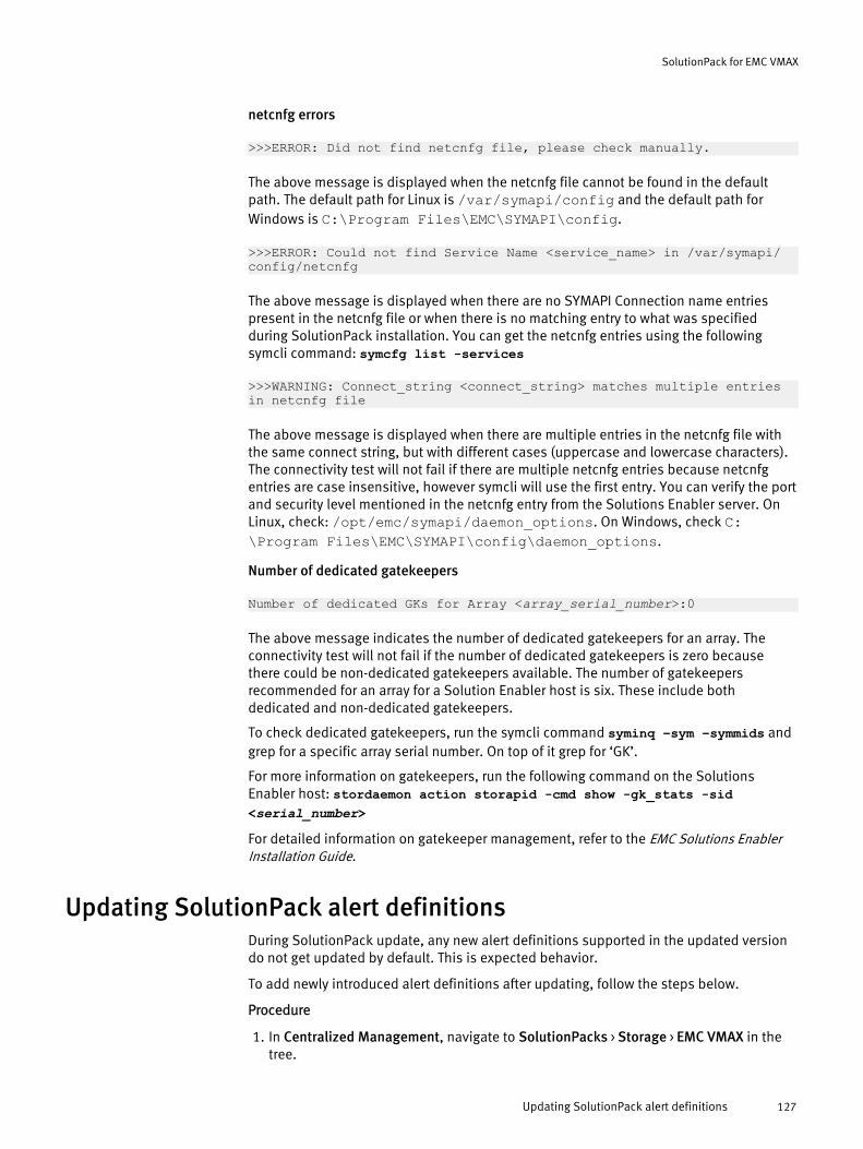
netcnfg errors
>>>ERROR: Did not find netcnfg file, please check manually.
The above message is displayed when the netcnfg file cannot be found in the defaultpath. The default path for Linux is /var/symapi/config and the default path forWindows is C:\Program Files\EMC\SYMAPI\config.
>>>ERROR: Could not find Service Name <service_name> in /var/symapi/config/netcnfg
The above message is displayed when there are no SYMAPI Connection name entriespresent in the netcnfg file or when there is no matching entry to what was specifiedduring SolutionPack installation. You can get the netcnfg entries using the followingsymcli command: symcfg list -services
>>>WARNING: Connect_string <connect_string> matches multiple entries in netcnfg file
The above message is displayed when there are multiple entries in the netcnfg file withthe same connect string, but with different cases (uppercase and lowercase characters).The connectivity test will not fail if there are multiple netcnfg entries because netcnfgentries are case insensitive, however symcli will use the first entry. You can verify the portand security level mentioned in the netcnfg entry from the Solutions Enabler server. OnLinux, check: /opt/emc/symapi/daemon_options. On Windows, check C:\Program Files\EMC\SYMAPI\config\daemon_options.
Number of dedicated gatekeepers
Number of dedicated GKs for Array <array_serial_number>:0
The above message indicates the number of dedicated gatekeepers for an array. Theconnectivity test will not fail if the number of dedicated gatekeepers is zero becausethere could be non-dedicated gatekeepers available. The number of gatekeepersrecommended for an array for a Solution Enabler host is six. These include bothdedicated and non-dedicated gatekeepers.
To check dedicated gatekeepers, run the symcli command syminq –sym –symmids andgrep for a specific array serial number. On top of it grep for ‘GK’.
For more information on gatekeepers, run the following command on the SolutionsEnabler host: stordaemon action storapid -cmd show -gk_stats -sid<serial_number>For detailed information on gatekeeper management, refer to the EMC Solutions EnablerInstallation Guide.
Updating SolutionPack alert definitionsDuring SolutionPack update, any new alert definitions supported in the updated versiondo not get updated by default. This is expected behavior.
To add newly introduced alert definitions after updating, follow the steps below.
Procedure
1. In Centralized Management, navigate to SolutionPacks > Storage > EMC VMAX in thetree.
SolutionPack for EMC VMAX
Updating SolutionPack alert definitions 127
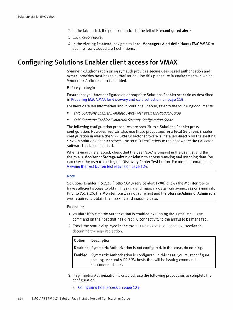
2. In the table, click the pen icon button to the left of Pre-configured alerts.
3. Click Reconfigure.
4. In the Alerting Frontend, navigate to Local Mananger > Alert definitions > EMC VMAX tosee the newly added alert definitions.
Configuring Solutions Enabler client access for VMAXSymmetrix Authorization using symauth provides secure user-based authorization andsymacl provides host-based authorization. Use this procedure in environments in whichSymmetrix Authorization is enabled.
Before you begin
Ensure that you have configured an appropriate Solutions Enabler scenario as describedin Preparing EMC VMAX for discovery and data collection on page 115.
For more detailed information about Solutions Enabler, refer to the following documents:
l EMC Solutions Enabler Symmetrix Array Management Product Guide
l EMC Solutions Enabler Symmetrix Security Configuration Guide
The following configuration procedures are specific to a Solutions Enabler proxyconfiguration. However, you can also use these procedures for a local Solutions Enablerconfiguration in which the ViPR SRM Collector software is installed directly on the existingSYMAPI Solutions Enabler server. The term "client" refers to the host where the Collectorsoftware has been installed.
When symauth is enabled, check that the user ‘apg’ is present in the user list and thatthe role is Monitor or Storage Admin or Admin to access masking and mapping data. Youcan check the user role using the Discovery Center Test button. For more information, see Viewing the Test button test results on page 124.
Note
Solutions Enabler 7.6.2.25 (hotfix 1843/service alert 1708) allows the Monitor role tohave sufficient access to obtain masking and mapping data from symaccess or symmask.Prior to 7.6.2.25, the Monitor role was not sufficient and the Storage Admin or Admin rolewas required to obtain the masking and mapping data.
Procedure
1. Validate if Symmetrix Authorization is enabled by running the symauth listcommand on the host that has direct FC connectivity to the arrays to be managed.
2. Check the status displayed in the the Authorization Control section todetermine the required action:
Option Description
Disabled Symmetrix Authorization is not configured. In this case, do nothing.
Enabled Symmetrix Authorization is configured. In this case, you must configurethe apg user and ViPR SRM hosts that will be issuing commands.Continue to step 3.
3. If Symmetrix Authorization is enabled, use the following procedures to complete theconfiguration:
a. Configuring host access on page 129
SolutionPack for EMC VMAX
128 EMC ViPR SRM 3.7 SolutionPack Installation and Configuration Guide
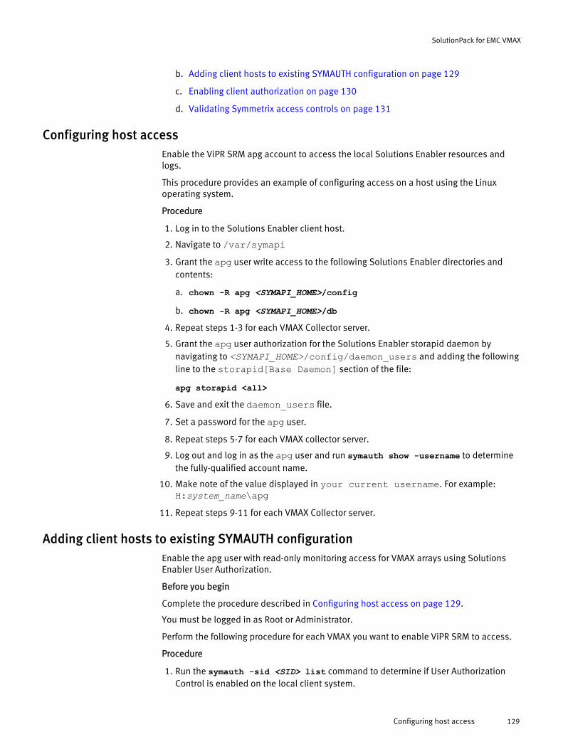
b. Adding client hosts to existing SYMAUTH configuration on page 129
c. Enabling client authorization on page 130
d. Validating Symmetrix access controls on page 131
Configuring host accessEnable the ViPR SRM apg account to access the local Solutions Enabler resources andlogs.
This procedure provides an example of configuring access on a host using the Linuxoperating system.
Procedure
1. Log in to the Solutions Enabler client host.
2. Navigate to /var/symapi3. Grant the apg user write access to the following Solutions Enabler directories and
contents:
a. chown -R apg <SYMAPI_HOME>/config
b. chown -R apg <SYMAPI_HOME>/db4. Repeat steps 1-3 for each VMAX Collector server.
5. Grant the apg user authorization for the Solutions Enabler storapid daemon bynavigating to <SYMAPI_HOME>/config/daemon_users and adding the followingline to the storapid[Base Daemon] section of the file:
apg storapid <all>6. Save and exit the daemon_users file.
7. Set a password for the apg user.
8. Repeat steps 5-7 for each VMAX collector server.
9. Log out and log in as the apg user and run symauth show -username to determinethe fully-qualified account name.
10. Make note of the value displayed in your current username. For example:H:system_name\apg
11. Repeat steps 9-11 for each VMAX Collector server.
Adding client hosts to existing SYMAUTH configurationEnable the apg user with read-only monitoring access for VMAX arrays using SolutionsEnabler User Authorization.
Before you begin
Complete the procedure described in Configuring host access on page 129.
You must be logged in as Root or Administrator.
Perform the following procedure for each VMAX you want to enable ViPR SRM to access.
Procedure
1. Run the symauth -sid <SID> list command to determine if User AuthorizationControl is enabled on the local client system.
SolutionPack for EMC VMAX
Configuring host access 129
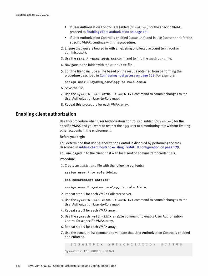
l If User Authorization Control is disabled (Disabled) for the specific VMAX,proceed to Enabling client authorization on page 130.
l If User Authorization Control is enabled (Enabled) and in use (Enforced) for thespecific VMAX, continue with this procedure.
2. Ensure that you are logged in with an existing privileged account (e.g., root oradministrator).
3. Use the find / -name auth.txt command to find the auth.txt file.
4. Navigate to the folder with the auth.txt file.
5. Edit the file to include a line based on the results obtained from performing theprocedure described in Configuring host access on page 129. For example:
assign user H:system_name\apg to role Admin;6. Save the file.
7. Use the symauth -sid <SID> -f auth.txt command to commit changes to theUser Authorization User-to-Role map.
8. Repeat this procedure for each VMAX array.
Enabling client authorizationUse this procedure when User Authorization Control is disabled (Disabled) for thespecific VMAX and you want to restrict the apg user to a monitoring role without limitingother accounts in the environment.
Before you begin
You determined that User Authorization Control is disabled by performing the taskdescribed in Adding client hosts to existing SYMAUTH configuration on page 129.
You are logged in to the client host with local root or administrator credentials.
Procedure
1. Create an auth.txt file with the following contents:
assign user * to role Admin;
set enforcement enforce;
assign user H:system_name\apg to role Admin;
2. Repeat step 1 for each VMAX Collector server.
3. Use the symauth -sid <SID> -f auth.txt command to commit changes to theUser Authorization User-to-Role map.
4. Repeat step 3 for each VMAX array.
5. Use the symauth -sid <SID> enable command to enable User AuthorizationControl for a specific VMAX array.
6. Repeat step 5 for each VMAX array.
7. Use the symauth list command to validate that User Authorization Control is enabledand enforced.
S Y M M E T R I X A U T H O R I Z A T I O N S T A T U S
Symmetrix ID: 000195700363
SolutionPack for EMC VMAX
130 EMC ViPR SRM 3.7 SolutionPack Installation and Configuration Guide
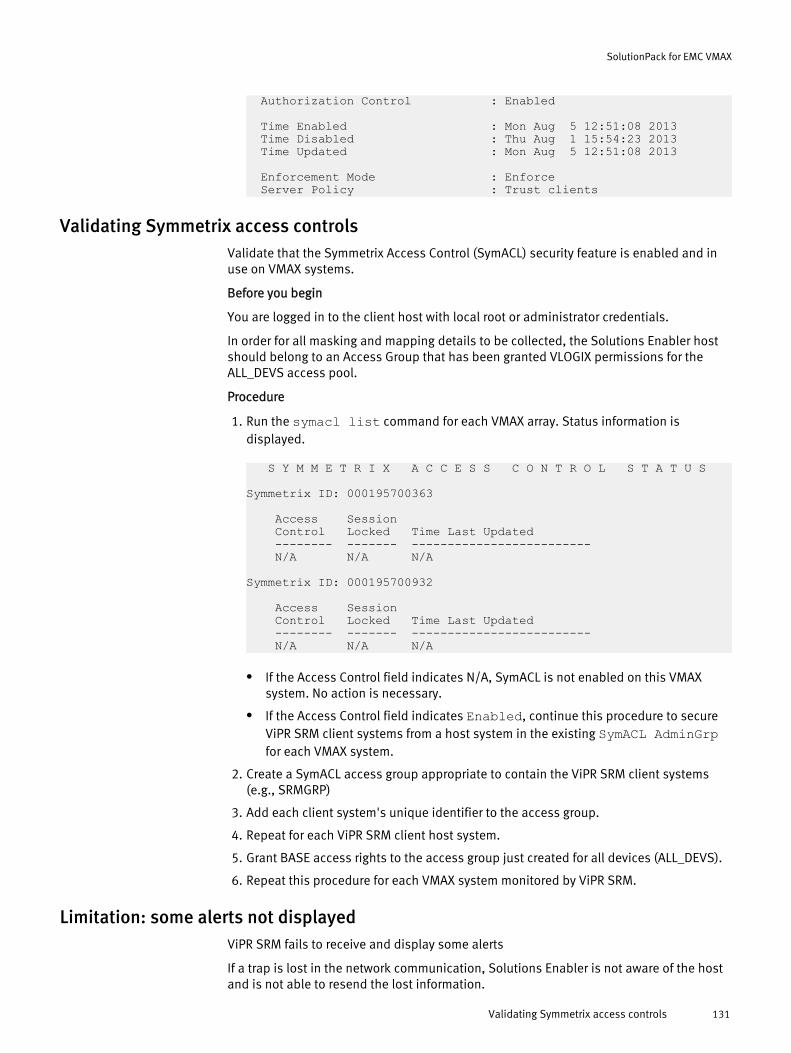
Authorization Control : Enabled
Time Enabled : Mon Aug 5 12:51:08 2013 Time Disabled : Thu Aug 1 15:54:23 2013 Time Updated : Mon Aug 5 12:51:08 2013
Enforcement Mode : Enforce Server Policy : Trust clients
Validating Symmetrix access controlsValidate that the Symmetrix Access Control (SymACL) security feature is enabled and inuse on VMAX systems.
Before you begin
You are logged in to the client host with local root or administrator credentials.
In order for all masking and mapping details to be collected, the Solutions Enabler hostshould belong to an Access Group that has been granted VLOGIX permissions for theALL_DEVS access pool.
Procedure
1. Run the symacl list command for each VMAX array. Status information isdisplayed.
S Y M M E T R I X A C C E S S C O N T R O L S T A T U S
Symmetrix ID: 000195700363
Access Session Control Locked Time Last Updated -------- ------- ------------------------- N/A N/A N/A
Symmetrix ID: 000195700932
Access Session Control Locked Time Last Updated -------- ------- ------------------------- N/A N/A N/A
l If the Access Control field indicates N/A, SymACL is not enabled on this VMAXsystem. No action is necessary.
l If the Access Control field indicates Enabled, continue this procedure to secureViPR SRM client systems from a host system in the existing SymACL AdminGrpfor each VMAX system.
2. Create a SymACL access group appropriate to contain the ViPR SRM client systems(e.g., SRMGRP)
3. Add each client system's unique identifier to the access group.
4. Repeat for each ViPR SRM client host system.
5. Grant BASE access rights to the access group just created for all devices (ALL_DEVS).
6. Repeat this procedure for each VMAX system monitored by ViPR SRM.
Limitation: some alerts not displayedViPR SRM fails to receive and display some alerts
If a trap is lost in the network communication, Solutions Enabler is not aware of the hostand is not able to resend the lost information.
SolutionPack for EMC VMAX
Validating Symmetrix access controls 131
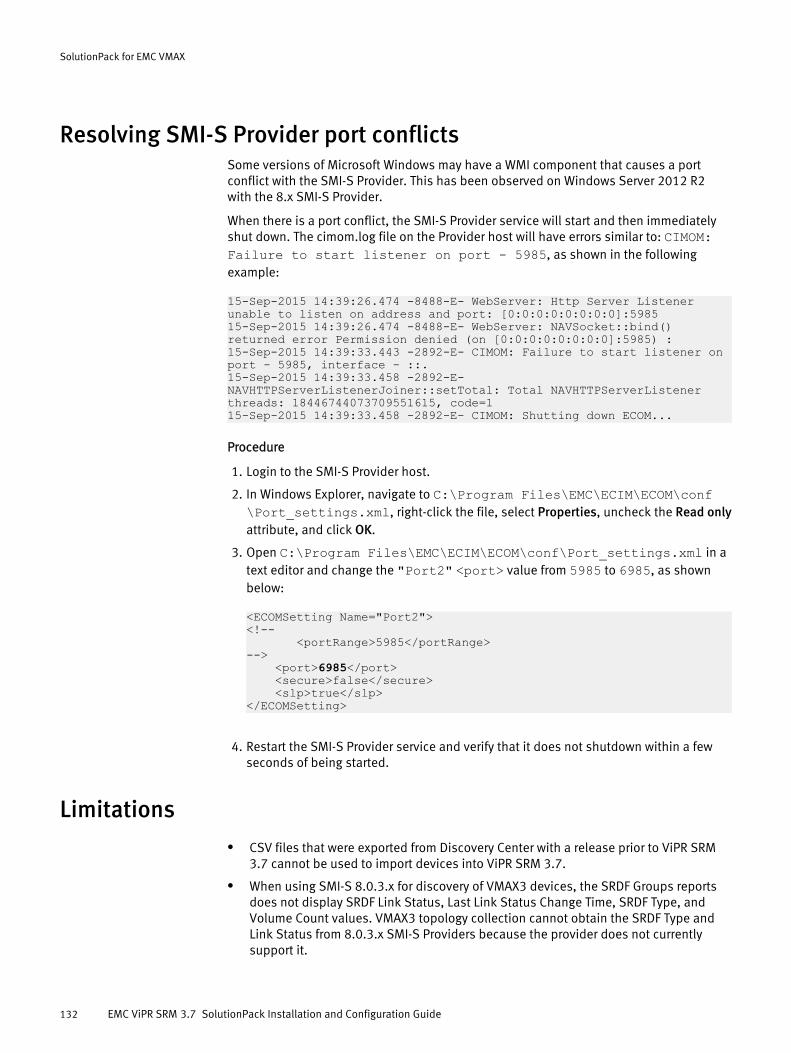
Resolving SMI-S Provider port conflictsSome versions of Microsoft Windows may have a WMI component that causes a portconflict with the SMI-S Provider. This has been observed on Windows Server 2012 R2with the 8.x SMI-S Provider.
When there is a port conflict, the SMI-S Provider service will start and then immediatelyshut down. The cimom.log file on the Provider host will have errors similar to: CIMOM:Failure to start listener on port - 5985, as shown in the followingexample:
15-Sep-2015 14:39:26.474 -8488-E- WebServer: Http Server Listener unable to listen on address and port: [0:0:0:0:0:0:0:0]:598515-Sep-2015 14:39:26.474 -8488-E- WebServer: NAVSocket::bind() returned error Permission denied (on [0:0:0:0:0:0:0:0]:5985) : 15-Sep-2015 14:39:33.443 -2892-E- CIMOM: Failure to start listener on port - 5985, interface - ::.15-Sep-2015 14:39:33.458 -2892-E- NAVHTTPServerListenerJoiner::setTotal: Total NAVHTTPServerListener threads: 18446744073709551615, code=115-Sep-2015 14:39:33.458 -2892-E- CIMOM: Shutting down ECOM...
Procedure
1. Login to the SMI-S Provider host.
2. In Windows Explorer, navigate to C:\Program Files\EMC\ECIM\ECOM\conf\Port_settings.xml, right-click the file, select Properties, uncheck the Read onlyattribute, and click OK.
3. Open C:\Program Files\EMC\ECIM\ECOM\conf\Port_settings.xml in atext editor and change the "Port2" <port> value from 5985 to 6985, as shownbelow:
<ECOMSetting Name="Port2"><!-- <portRange>5985</portRange>--> <port>6985</port> <secure>false</secure> <slp>true</slp></ECOMSetting>
4. Restart the SMI-S Provider service and verify that it does not shutdown within a fewseconds of being started.
Limitationsl CSV files that were exported from Discovery Center with a release prior to ViPR SRM
3.7 cannot be used to import devices into ViPR SRM 3.7.
l When using SMI-S 8.0.3.x for discovery of VMAX3 devices, the SRDF Groups reportsdoes not display SRDF Link Status, Last Link Status Change Time, SRDF Type, andVolume Count values. VMAX3 topology collection cannot obtain the SRDF Type andLink Status from 8.0.3.x SMI-S Providers because the provider does not currentlysupport it.
SolutionPack for EMC VMAX
132 EMC ViPR SRM 3.7 SolutionPack Installation and Configuration Guide

l When using versions of SMI-S earlier than 8.1.0.0 for VMAX collection, unmaskedGatekeeper or SRDF devices may have LUN metrics with an incorrect"ismapped=false" property when the devices are actually mapped.
l After upgrading to ViPR SRM 3.7, it is possible that some VMAX devices will notcollect Unisphere for VMAX performance metrics. This can occur because only thefirst Unisphere for VMAX host in the SolutionPack configuration is configured tocollect metrics after the upgrade while others are ignored. It is recommended to runthe Test script in Discovery Center on all VMAX devices to identify the devices thatmust be reconfigured.
SolutionPack for EMC VMAX
Limitations 133

SolutionPack for EMC VMAX
134 EMC ViPR SRM 3.7 SolutionPack Installation and Configuration Guide

CHAPTER 18
SolutionPack for EMC VNX
l Overview............................................................................................................. 136l Preparing your VNX for discovery and data collection.......................................... 137l Installing the SolutionPack..................................................................................139l Updating SolutionPack alert definitions.............................................................. 141l Changing VNX object credentials using Discovery Center.....................................142l Resolving collector communication errors........................................................... 143l Limitations..........................................................................................................144
SolutionPack for EMC VNX 135
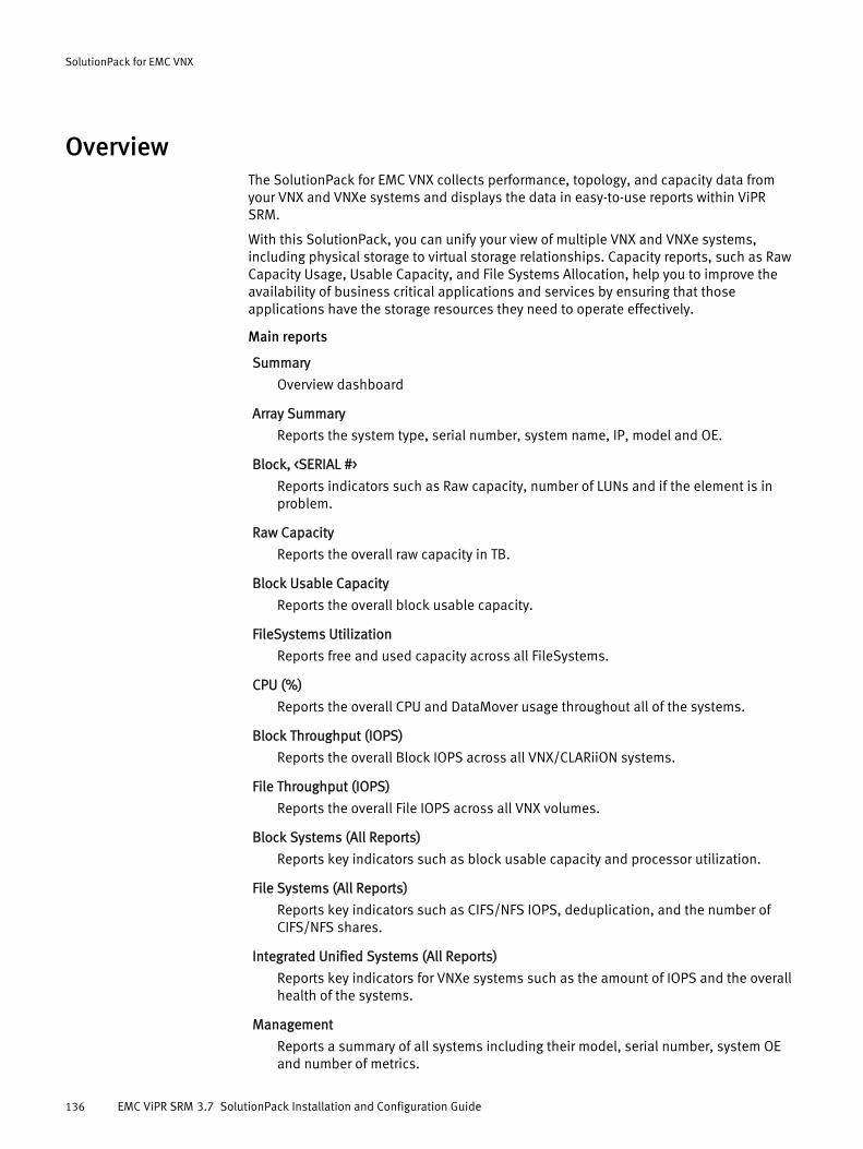
OverviewThe SolutionPack for EMC VNX collects performance, topology, and capacity data fromyour VNX and VNXe systems and displays the data in easy-to-use reports within ViPRSRM.
With this SolutionPack, you can unify your view of multiple VNX and VNXe systems,including physical storage to virtual storage relationships. Capacity reports, such as RawCapacity Usage, Usable Capacity, and File Systems Allocation, help you to improve theavailability of business critical applications and services by ensuring that thoseapplications have the storage resources they need to operate effectively.
Main reports
Summary
Overview dashboard
Array Summary
Reports the system type, serial number, system name, IP, model and OE.
Block, <SERIAL #>
Reports indicators such as Raw capacity, number of LUNs and if the element is inproblem.
Raw Capacity
Reports the overall raw capacity in TB.
Block Usable Capacity
Reports the overall block usable capacity.
FileSystems Utilization
Reports free and used capacity across all FileSystems.
CPU (%)
Reports the overall CPU and DataMover usage throughout all of the systems.
Block Throughput (IOPS)
Reports the overall Block IOPS across all VNX/CLARiiON systems.
File Throughput (IOPS)
Reports the overall File IOPS across all VNX volumes.
Block Systems (All Reports)
Reports key indicators such as block usable capacity and processor utilization.
File Systems (All Reports)
Reports key indicators such as CIFS/NFS IOPS, deduplication, and the number ofCIFS/NFS shares.
Integrated Unified Systems (All Reports)
Reports key indicators for VNXe systems such as the amount of IOPS and the overallhealth of the systems.
Management
Reports a summary of all systems including their model, serial number, system OEand number of metrics.
SolutionPack for EMC VNX
136 EMC ViPR SRM 3.7 SolutionPack Installation and Configuration Guide
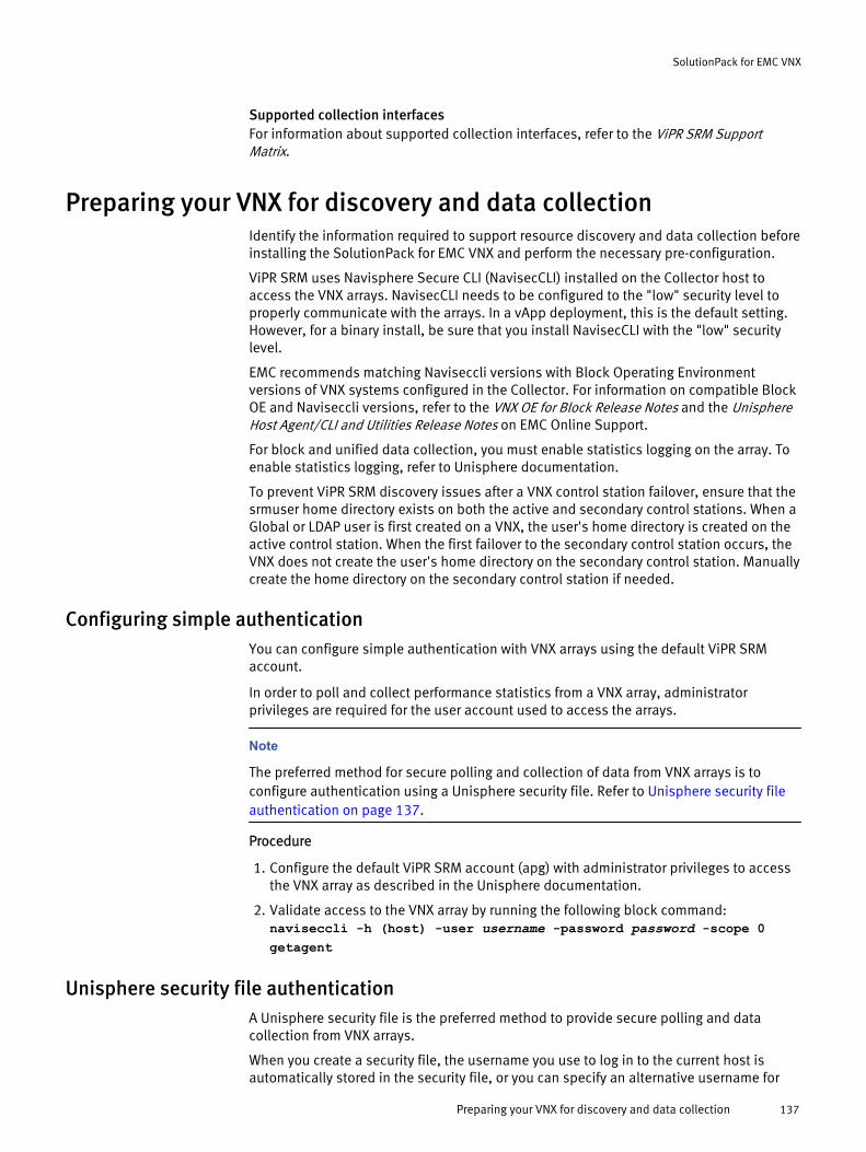
Supported collection interfacesFor information about supported collection interfaces, refer to the ViPR SRM SupportMatrix.
Preparing your VNX for discovery and data collectionIdentify the information required to support resource discovery and data collection beforeinstalling the SolutionPack for EMC VNX and perform the necessary pre-configuration.
ViPR SRM uses Navisphere Secure CLI (NavisecCLI) installed on the Collector host toaccess the VNX arrays. NavisecCLI needs to be configured to the "low" security level toproperly communicate with the arrays. In a vApp deployment, this is the default setting.However, for a binary install, be sure that you install NavisecCLI with the "low" securitylevel.
EMC recommends matching Naviseccli versions with Block Operating Environmentversions of VNX systems configured in the Collector. For information on compatible BlockOE and Naviseccli versions, refer to the VNX OE for Block Release Notes and the UnisphereHost Agent/CLI and Utilities Release Notes on EMC Online Support.
For block and unified data collection, you must enable statistics logging on the array. Toenable statistics logging, refer to Unisphere documentation.
To prevent ViPR SRM discovery issues after a VNX control station failover, ensure that thesrmuser home directory exists on both the active and secondary control stations. When aGlobal or LDAP user is first created on a VNX, the user's home directory is created on theactive control station. When the first failover to the secondary control station occurs, theVNX does not create the user's home directory on the secondary control station. Manuallycreate the home directory on the secondary control station if needed.
Configuring simple authenticationYou can configure simple authentication with VNX arrays using the default ViPR SRMaccount.
In order to poll and collect performance statistics from a VNX array, administratorprivileges are required for the user account used to access the arrays.
Note
The preferred method for secure polling and collection of data from VNX arrays is toconfigure authentication using a Unisphere security file. Refer to Unisphere security fileauthentication on page 137.
Procedure
1. Configure the default ViPR SRM account (apg) with administrator privileges to accessthe VNX array as described in the Unisphere documentation.
2. Validate access to the VNX array by running the following block command:naviseccli -h (host) -user username -password password -scope 0getagent
Unisphere security file authenticationA Unisphere security file is the preferred method to provide secure polling and datacollection from VNX arrays.
When you create a security file, the username you use to log in to the current host isautomatically stored in the security file, or you can specify an alternative username for
SolutionPack for EMC VNX
Preparing your VNX for discovery and data collection 137
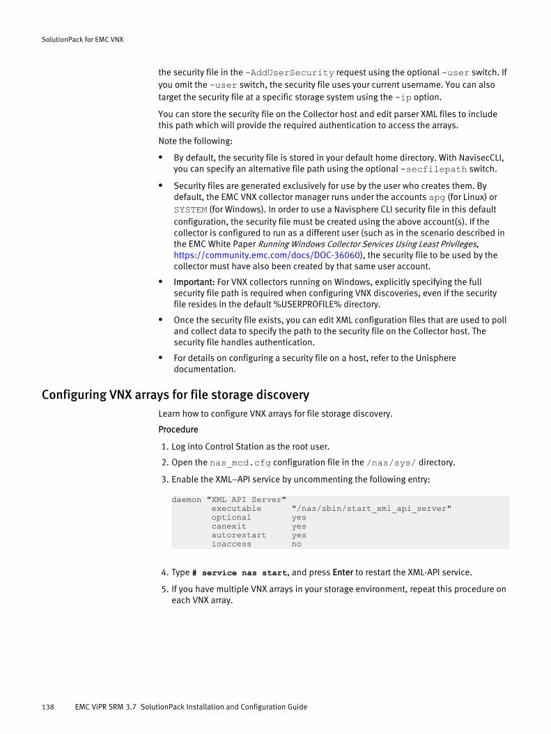
the security file in the -AddUserSecurity request using the optional -user switch. Ifyou omit the -user switch, the security file uses your current username. You can alsotarget the security file at a specific storage system using the -ip option.
You can store the security file on the Collector host and edit parser XML files to includethis path which will provide the required authentication to access the arrays.
Note the following:
l By default, the security file is stored in your default home directory. With NavisecCLI,you can specify an alternative file path using the optional -secfilepath switch.
l Security files are generated exclusively for use by the user who creates them. Bydefault, the EMC VNX collector manager runs under the accounts apg (for Linux) orSYSTEM (for Windows). In order to use a Navisphere CLI security file in this defaultconfiguration, the security file must be created using the above account(s). If thecollector is configured to run as a different user (such as in the scenario described inthe EMC White Paper Running Windows Collector Services Using Least Privileges, https://community.emc.com/docs/DOC-36060), the security file to be used by thecollector must have also been created by that same user account.
l Important: For VNX collectors running on Windows, explicitly specifying the fullsecurity file path is required when configuring VNX discoveries, even if the securityfile resides in the default %USERPROFILE% directory.
l Once the security file exists, you can edit XML configuration files that are used to polland collect data to specify the path to the security file on the Collector host. Thesecurity file handles authentication.
l For details on configuring a security file on a host, refer to the Unispheredocumentation.
Configuring VNX arrays for file storage discoveryLearn how to configure VNX arrays for file storage discovery.
Procedure
1. Log into Control Station as the root user.
2. Open the nas_mcd.cfg configuration file in the /nas/sys/ directory.
3. Enable the XML–API service by uncommenting the following entry:
daemon "XML API Server" executable "/nas/sbin/start_xml_api_server" optional yes canexit yes autorestart yes ioaccess no
4. Type # service nas start, and press Enter to restart the XML-API service.
5. If you have multiple VNX arrays in your storage environment, repeat this procedure oneach VNX array.
SolutionPack for EMC VNX
138 EMC ViPR SRM 3.7 SolutionPack Installation and Configuration Guide
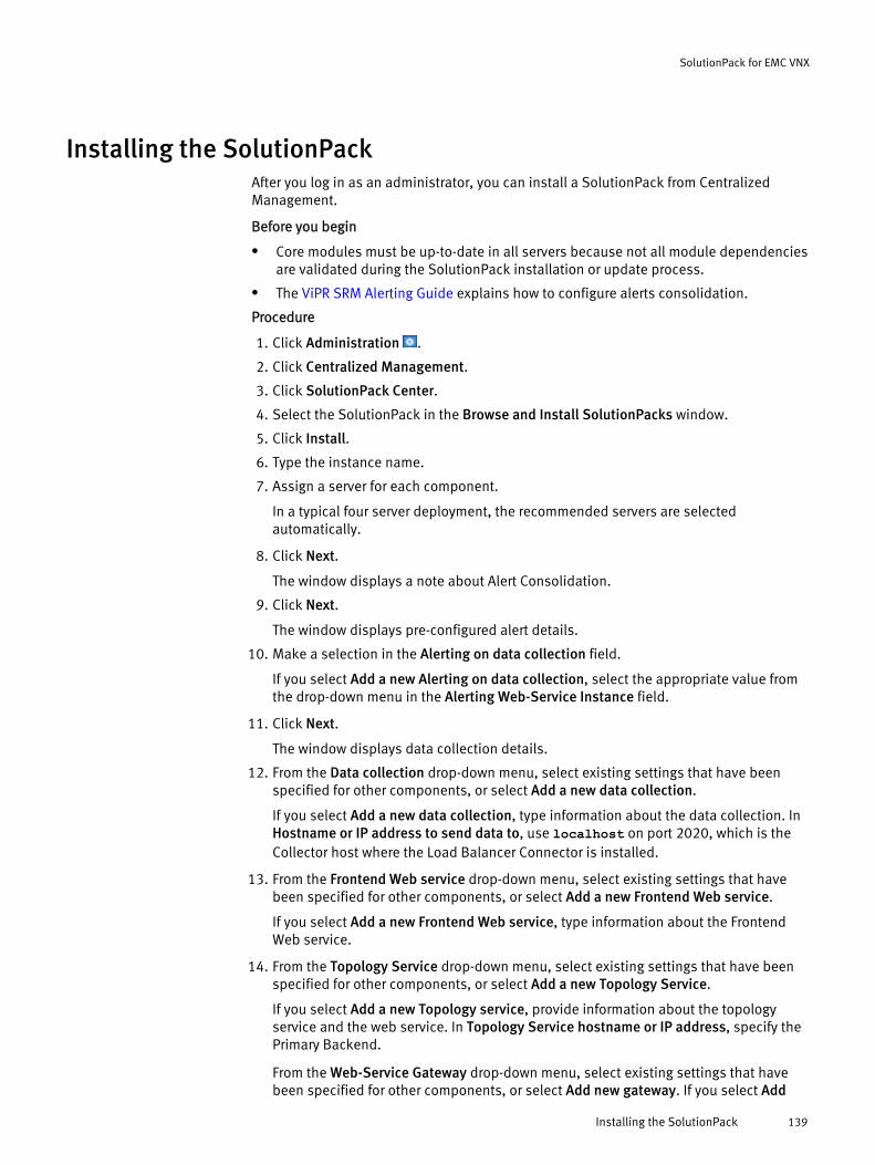
Installing the SolutionPackAfter you log in as an administrator, you can install a SolutionPack from CentralizedManagement.
Before you begin
l Core modules must be up-to-date in all servers because not all module dependenciesare validated during the SolutionPack installation or update process.
l The ViPR SRM Alerting Guide explains how to configure alerts consolidation.
Procedure
1. Click Administration .
2. Click Centralized Management.
3. Click SolutionPack Center.
4. Select the SolutionPack in the Browse and Install SolutionPacks window.
5. Click Install.
6. Type the instance name.
7. Assign a server for each component.
In a typical four server deployment, the recommended servers are selectedautomatically.
8. Click Next.
The window displays a note about Alert Consolidation.
9. Click Next.
The window displays pre-configured alert details.
10. Make a selection in the Alerting on data collection field.
If you select Add a new Alerting on data collection, select the appropriate value fromthe drop-down menu in the Alerting Web-Service Instance field.
11. Click Next.
The window displays data collection details.
12. From the Data collection drop-down menu, select existing settings that have beenspecified for other components, or select Add a new data collection.
If you select Add a new data collection, type information about the data collection. InHostname or IP address to send data to, use localhost on port 2020, which is theCollector host where the Load Balancer Connector is installed.
13. From the Frontend Web service drop-down menu, select existing settings that havebeen specified for other components, or select Add a new Frontend Web service.
If you select Add a new Frontend Web service, type information about the FrontendWeb service.
14. From the Topology Service drop-down menu, select existing settings that have beenspecified for other components, or select Add a new Topology Service.
If you select Add a new Topology service, provide information about the topologyservice and the web service. In Topology Service hostname or IP address, specify thePrimary Backend.
From the Web-Service Gateway drop-down menu, select existing settings that havebeen specified for other components, or select Add new gateway. If you select Add
SolutionPack for EMC VNX
Installing the SolutionPack 139

new gateway, provide information about the web-service gateway where the topologyservice resides.
15. In Event server hostname or IP address, select the Backend host on which the EventsListener is installed.
16. In Event server port number select the port number for the event server.
17. Select Configure Alert consolidation.
18. In Alert consolidation server hostname or IP address, select the Primary Backendhost.
19. In Alert consolidation server port number, select the port used for alert consolidation.
20. In Naviseccli Path, type the path if using a non-default path, or leave blank if you areusing the default path.
21. Select Use advanced settings to configure polling and alert settings.
22. Click Next.
23. From the Event database drop-down menu, select existing settings that have beenspecified for other components, or select Add a new Event database.
If you select Add a new Event database, type the information about the new eventdatabase.
24. Click Next.
25. In Administration Web-Service Instance, select the Frontend host.
26. Click Install.
27. Click Ok. Monitor the installation logs to ensure that the installation completessuccessfully.
28. Click Discovery Center > Devices Management.
29. Click VNX.
30. Click Add new device.
31. From Server, select the server where the device will be dispatched.
32. From Instance, select the instance of the emc-vnx-collect where the device will bedispatched.
33. In VNX type, select Block Only, NAS Gateway, Unified/File, or Integrated Unified(VNXe).
If the following fields appear, enter the information specified:
a. In Unique friendly name for the VNX system, type the name.
b. In SP A IP, type the IP address of the SPA.
c. In SP B IP, type the IP address of the SPB.
d. In Use Naviseccli security file, select this checkbox if you are using the securityfile.
e. In Naviseccli User Scope, select LDAP, Global or Local.
f. In Naviseccli Username and Naviseccli Password, type the Naviseccli credentialsfor the block storage systems.
g. In Primary control station IP, type the IP address of the primary control station.
h. In Secondary control station IP, type the IP address of the secondary controlstation.
SolutionPack for EMC VNX
140 EMC ViPR SRM 3.7 SolutionPack Installation and Configuration Guide
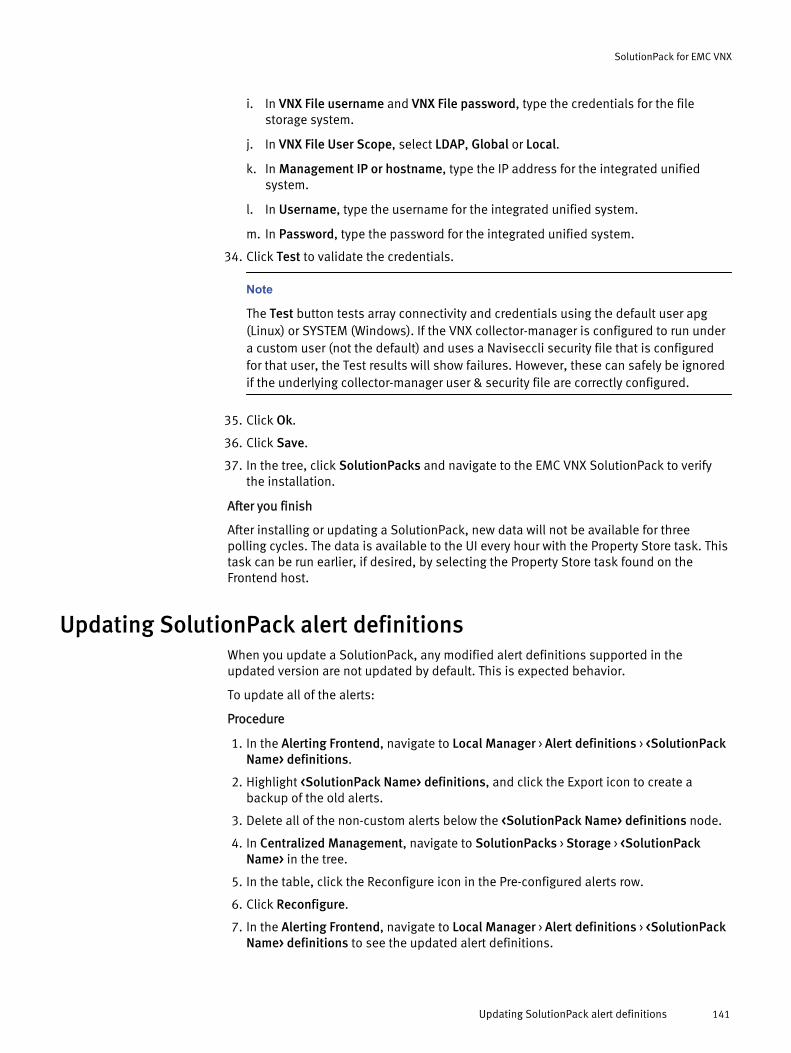
i. In VNX File username and VNX File password, type the credentials for the filestorage system.
j. In VNX File User Scope, select LDAP, Global or Local.
k. In Management IP or hostname, type the IP address for the integrated unifiedsystem.
l. In Username, type the username for the integrated unified system.
m. In Password, type the password for the integrated unified system.
34. Click Test to validate the credentials.
Note
The Test button tests array connectivity and credentials using the default user apg(Linux) or SYSTEM (Windows). If the VNX collector-manager is configured to run undera custom user (not the default) and uses a Naviseccli security file that is configuredfor that user, the Test results will show failures. However, these can safely be ignoredif the underlying collector-manager user & security file are correctly configured.
35. Click Ok.
36. Click Save.
37. In the tree, click SolutionPacks and navigate to the EMC VNX SolutionPack to verifythe installation.
After you finish
After installing or updating a SolutionPack, new data will not be available for threepolling cycles. The data is available to the UI every hour with the Property Store task. Thistask can be run earlier, if desired, by selecting the Property Store task found on theFrontend host.
Updating SolutionPack alert definitionsWhen you update a SolutionPack, any modified alert definitions supported in theupdated version are not updated by default. This is expected behavior.
To update all of the alerts:
Procedure
1. In the Alerting Frontend, navigate to Local Manager > Alert definitions > <SolutionPackName> definitions.
2. Highlight <SolutionPack Name> definitions, and click the Export icon to create abackup of the old alerts.
3. Delete all of the non-custom alerts below the <SolutionPack Name> definitions node.
4. In Centralized Management, navigate to SolutionPacks > Storage > <SolutionPackName> in the tree.
5. In the table, click the Reconfigure icon in the Pre-configured alerts row.
6. Click Reconfigure.
7. In the Alerting Frontend, navigate to Local Manager > Alert definitions > <SolutionPackName> definitions to see the updated alert definitions.
SolutionPack for EMC VNX
Updating SolutionPack alert definitions 141
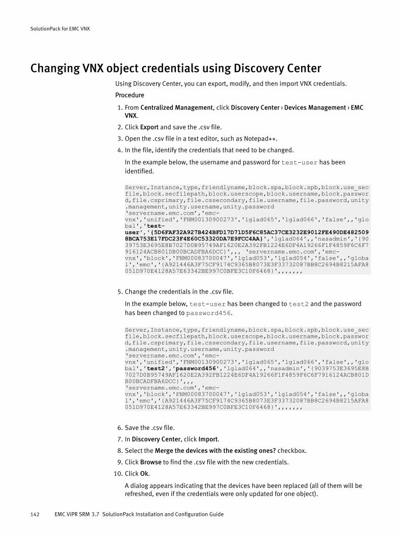
Changing VNX object credentials using Discovery CenterUsing Discovery Center, you can export, modify, and then import VNX credentials.
Procedure
1. From Centralized Management, click Discovery Center > Devices Management > EMCVNX.
2. Click Export and save the .csv file.
3. Open the .csv file in a text editor, such as Notepad++.
4. In the file, identify the credentials that need to be changed.
In the example below, the username and password for test-user has beenidentified.
Server,Instance,type,friendlyname,block.spa,block.spb,block.use_secfile,block.secfilepath,block.userscope,block.username,block.password,file.csprimary,file.cssecondary,file.username,file.password,unity.management,unity.username,unity.password ‘servername.emc.com’,'emc-vnx','unified','FNM00130900273','lglad065','lglad066','false',,'global','test-user','{5D6FAF32A927B424BFD17D71D5F6C85AC37CE3232E9012FE490DE4825098BCA753E17FDC23F4E60C53320DA7E9FCC4AA}','lglad064',,'nasadmin','{9039753E3695E8B7027D0B95749AF1620E2A392FB1224E6DF4A19266F1F4859F6C6F7916124ACB801DB00BCADFBA6DCC}',,, ‘servername.emc.com’,'emc-vnx','block','FNM00083700047','lglad053','lglad054','false',,'global','emc','{A921446A3F75CF9174C9365B8073E3F33732087BB8C2694B8215AFA8051D970E4128A57E63342BE997C0BFE3C10F6468}',,,,,,,
5. Change the credentials in the .csv file.
In the example below, test-user has been changed to test2 and the passwordhas been changed to password456.
Server,Instance,type,friendlyname,block.spa,block.spb,block.use_secfile,block.secfilepath,block.userscope,block.username,block.password,file.csprimary,file.cssecondary,file.username,file.password,unity.management,unity.username,unity.password‘servername.emc.com’,'emc-vnx','unified','FNM00130900273','lglad065','lglad066','false',,'global','test2','password456','lglad064',,'nasadmin','{9039753E3695E8B7027D0B95749AF1620E2A392FB1224E6DF4A19266F1F4859F6C6F7916124ACB801DB00BCADFBA6DCC}',,,‘servername.emc.com’,'emc-vnx','block','FNM00083700047','lglad053','lglad054','false',,'global','emc','{A921446A3F75CF9174C9365B8073E3F33732087BB8C2694B8215AFA8051D970E4128A57E63342BE997C0BFE3C10F6468}',,,,,,,
6. Save the .csv file.
7. In Discovery Center, click Import.
8. Select the Merge the devices with the existing ones? checkbox.
9. Click Browse to find the .csv file with the new credentials.
10. Click Ok.
A dialog appears indicating that the devices have been replaced (all of them will berefreshed, even if the credentials were only updated for one object).
SolutionPack for EMC VNX
142 EMC ViPR SRM 3.7 SolutionPack Installation and Configuration Guide
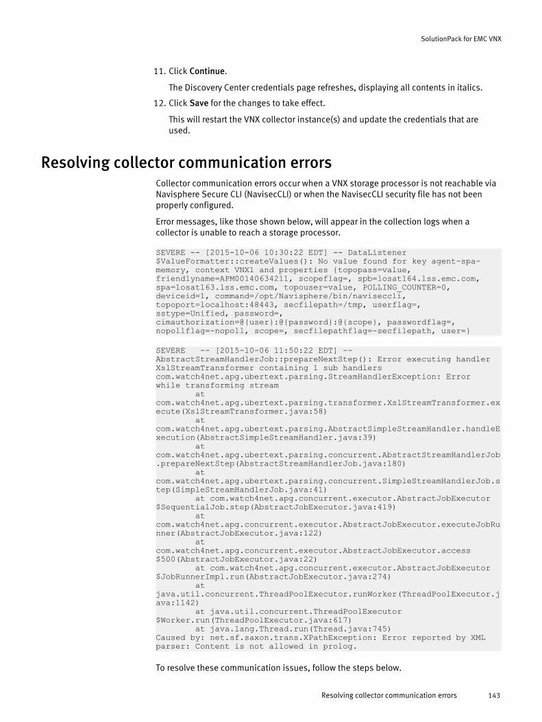
11. Click Continue.
The Discovery Center credentials page refreshes, displaying all contents in italics.
12. Click Save for the changes to take effect.
This will restart the VNX collector instance(s) and update the credentials that areused.
Resolving collector communication errorsCollector communication errors occur when a VNX storage processor is not reachable viaNavisphere Secure CLI (NavisecCLI) or when the NavisecCLI security file has not beenproperly configured.
Error messages, like those shown below, will appear in the collection logs when acollector is unable to reach a storage processor.
SEVERE -- [2015-10-06 10:30:22 EDT] -- DataListener$ValueFormatter::createValues(): No value found for key agent-spa-memory, context VNX1 and properties {topopass=value, friendlyname=APM00140634211, scopeflag=, spb=losat164.lss.emc.com, spa=losat163.lss.emc.com, topouser=value, POLLING_COUNTER=0, deviceid=1, command=/opt/Navisphere/bin/naviseccli, topoport=localhost:48443, secfilepath=/tmp, userflag=, sstype=Unified, password=, cimauthorization=@{user}:@{password}:@{scope}, passwordflag=, nopollflag=-nopoll, scope=, secfilepathflag=-secfilepath, user=}
SEVERE -- [2015-10-06 11:50:22 EDT] -- AbstractStreamHandlerJob::prepareNextStep(): Error executing handler XslStreamTransformer containing 1 sub handlerscom.watch4net.apg.ubertext.parsing.StreamHandlerException: Error while transforming stream at com.watch4net.apg.ubertext.parsing.transformer.XslStreamTransformer.execute(XslStreamTransformer.java:58) at com.watch4net.apg.ubertext.parsing.AbstractSimpleStreamHandler.handleExecution(AbstractSimpleStreamHandler.java:39) at com.watch4net.apg.ubertext.parsing.concurrent.AbstractStreamHandlerJob.prepareNextStep(AbstractStreamHandlerJob.java:180) at com.watch4net.apg.ubertext.parsing.concurrent.SimpleStreamHandlerJob.step(SimpleStreamHandlerJob.java:41) at com.watch4net.apg.concurrent.executor.AbstractJobExecutor$SequentialJob.step(AbstractJobExecutor.java:419) at com.watch4net.apg.concurrent.executor.AbstractJobExecutor.executeJobRunner(AbstractJobExecutor.java:122) at com.watch4net.apg.concurrent.executor.AbstractJobExecutor.access$500(AbstractJobExecutor.java:22) at com.watch4net.apg.concurrent.executor.AbstractJobExecutor$JobRunnerImpl.run(AbstractJobExecutor.java:274) at java.util.concurrent.ThreadPoolExecutor.runWorker(ThreadPoolExecutor.java:1142) at java.util.concurrent.ThreadPoolExecutor$Worker.run(ThreadPoolExecutor.java:617) at java.lang.Thread.run(Thread.java:745)Caused by: net.sf.saxon.trans.XPathException: Error reported by XML parser: Content is not allowed in prolog.
To resolve these communication issues, follow the steps below.
SolutionPack for EMC VNX
Resolving collector communication errors 143
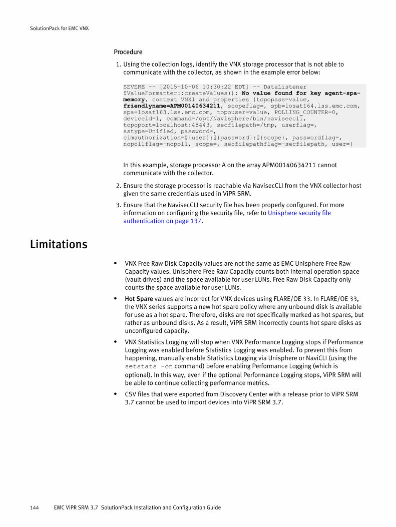
Procedure
1. Using the collection logs, identify the VNX storage processor that is not able tocommunicate with the collector, as shown in the example error below:
SEVERE -- [2015-10-06 10:30:22 EDT] -- DataListener$ValueFormatter::createValues(): No value found for key agent-spa-memory, context VNX1 and properties {topopass=value, friendlyname=APM00140634211, scopeflag=, spb=losat164.lss.emc.com, spa=losat163.lss.emc.com, topouser=value, POLLING_COUNTER=0, deviceid=1, command=/opt/Navisphere/bin/naviseccli, topoport=localhost:48443, secfilepath=/tmp, userflag=, sstype=Unified, password=, cimauthorization=@{user}:@{password}:@{scope}, passwordflag=, nopollflag=-nopoll, scope=, secfilepathflag=-secfilepath, user=}
In this example, storage processor A on the array APM00140634211 cannotcommunicate with the collector.
2. Ensure the storage processor is reachable via NavisecCLI from the VNX collector hostgiven the same credentials used in ViPR SRM.
3. Ensure that the NavisecCLI security file has been properly configured. For moreinformation on configuring the security file, refer to Unisphere security fileauthentication on page 137.
Limitationsl VNX Free Raw Disk Capacity values are not the same as EMC Unisphere Free Raw
Capacity values. Unisphere Free Raw Capacity counts both internal operation space(vault drives) and the space available for user LUNs. Free Raw Disk Capacity onlycounts the space available for user LUNs.
l Hot Spare values are incorrect for VNX devices using FLARE/OE 33. In FLARE/OE 33,the VNX series supports a new hot spare policy where any unbound disk is availablefor use as a hot spare. Therefore, disks are not specifically marked as hot spares, butrather as unbound disks. As a result, ViPR SRM incorrectly counts hot spare disks asunconfigured capacity.
l VNX Statistics Logging will stop when VNX Performance Logging stops if PerformanceLogging was enabled before Statistics Logging was enabled. To prevent this fromhappening, manually enable Statistics Logging via Unisphere or NaviCLI (using thesetstats -on command) before enabling Performance Logging (which isoptional). In this way, even if the optional Performance Logging stops, ViPR SRM willbe able to continue collecting performance metrics.
l CSV files that were exported from Discovery Center with a release prior to ViPR SRM3.7 cannot be used to import devices into ViPR SRM 3.7.
SolutionPack for EMC VNX
144 EMC ViPR SRM 3.7 SolutionPack Installation and Configuration Guide
CHAPTER 19
SolutionPack for EMC VPLEX
l Overview............................................................................................................. 146l Installing the SolutionPack..................................................................................147l Configure VPLEX SNMP........................................................................................149l Limitations..........................................................................................................149
SolutionPack for EMC VPLEX 145

OverviewThe SolutionPack for EMC VPLEX collects performance, topology, and capacity data fromyour VPLEX systems and displays the data in easy-to-use reports within ViPR SRM.
With this SolutionPack, you can unify your view of multiple VPLEX systems, includingphysical storage to virtual storage relationships. Capacity reports, such as Thick, Thin,Allocated and Not Allocated, help you to improve the availability of business criticalapplications and services by ensuring that those applications have the storage resourcesthey need to operate effectively.
Main reports
SolutionPack / EMC VPLEX
Overview dashboard
Back-end Throughput (IOPS)
Reports the Back-end throughput (IOPS) for all VPLEX systems
Front-end Throughput (IOPS)
Reports the Front-end throughput (IOPS) for all VPLEX systems
Front-end Bandwidth (KB/s)
Reports the Front-end bandwidth (KB/s) for all VPLEX systems
Local Storage Capacity
Reports the overall storage capacity, including key indicators related to Capacity andVolumes
Distributed Storage Capacity
Reports the overall distributed storage capacity for all VPLEX systems
Shared Storage Capacity
Reports the overall shared storage capacity for all VPLEX systems
Clusters
Drill-down report containing a summary of all clusters, including the cluster name,version, management IP, directors count, arrays count and virtual volumes count
Performance Reports
Drill-down report that reports Directors Processor (Global), Directors Processor (perCPU), and the Heap Used (%)
Capacity Reports
Drill-down report containing key indicators of Host to Physical Array End-To-EndView, Capacity per Array and Thick versus Thin
Port Inventory
Summarizes the ports on VPLEX systems
TopN Storage View Reports
Drill-down report containing key indicators of the TopN Storage Views per Capacity,IOPs and Throughput
Distributed Storage
Summarizes the distributed storage devices on VPLEX systems
SolutionPack for EMC VPLEX
146 EMC ViPR SRM 3.7 SolutionPack Installation and Configuration Guide
Inactive Device and Components reports
Shows devices & sub-components which haven't been updated in more than 24hours
Supported collection interfacesFor information about supported collection interfaces, refer to the ViPR SRM SupportMatrix.
Installing the SolutionPack
Before you begin
l Before installing confirm that the VPLEX model is supported.
l ViPR SRM core modules must be up-to-date in all servers because not all moduledependencies are validated during the SolutionPack installation or update process.
l Identify the VPLEX type (Geo, Metro or Local), VPLEX Cluster IP/Hostname, VPLEXCluster Serial Number, and valid credentials.
l Check that a sink file is listed for each of the directors on the cluster.If the sink file is not listed for a director, check that the clusters and their associateddirectors are operating correctly. If the monitors are not created the SolutionPack canstill be installed, but the performance data will be missing for the correspondingdirectors. For instance, if cluster-2 is down then you could still install theSolutionPack but it will not collect any performance data for directors on that cluster.
l While adding a new device, ensure that the correct VPLEX type is selected. Do not adda Geo or Metro VPLEX System as two separate Local VPLEX Systems.
l While adding a new device, ensure that cluster 1 IP and serial number are notinterchanged with the cluster 2 IP and Serial Number.
Procedure
1. Click Administration .
2. Click Centralized Management.
3. Click SolutionPack Center.
4. Select the SolutionPack in the Browse and Install SolutionPacks window.
5. Click Install.
6. Type the instance name.
7. Assign a server for each component.
In a typical four server deployment, the recommended servers are selectedautomatically.
8. Click Next.
The window displays pre-configured alert details.
9. From the Alerting Consolidation drop-down menu, select the Primary Backend host.
10. Click Next.
The window displays data collection details.
11. From the Data collection drop-down menu, select existing settings that have beenspecified for other components, or select Add a new data collection.
SolutionPack for EMC VPLEX
Installing the SolutionPack 147

If you select Add a new data collection, type information about the data collection. InHostname or IP address to send data to, use localhost on port 2020, which is theCollector host where the Load Balancer Connector is installed.
12. Leave Enable Topology Backend on data collected checked.
13. From the Topology Service drop-down menu, select existing settings that have beenspecified for other components, or select Add a new Topology Service.
If you select Add a new Topology service, provide information about the topologyservice and the web service. In Topology Service hostname or IP address, specify thePrimary Backend.
From the Web-Service Gateway drop-down menu, select existing settings that havebeen specified for other components, or select Add new gateway. If you select Addnew gateway, provide information about the web-service gateway where the topologyservice resides.
14. Select Use advanced settings to configure polling settings.
15. Click Next.
The window displays reports settings.
16. Click Install.
17. Click Ok. Monitor the installation logs to ensure that the installation completessuccessfully.
18. Click Discovery Center > Devices Management.
19. Click VPLEX.
20. Click Add new device.
21. In the VPLEX section, provide the cluster host and authentication details for yourVPLEX system.
The default username for the VPLEX is service and the default password isMi@Dim7T.
It is important to enter the cluster information correctly, clusters are mapped to theircorrect number. Interchanging cluster IPs and SN results in a failure to collectperformance data.
Be sure to select the correct VPLEX type while adding the device. If you are adding aVPLEX Metro or VPLEX Geo, select the Geo/Metro VPLEX type from the drop-down andenter both VPLEX cluster details. If you are adding a VPLEX Local, select the LocalVPLEX type from the drop-down and enter the VPLEX cluster details. Do not add a Geoor Metro VPLEX System as two separate Local VPLEX Systems.
22. Click Test to validate the credentials.
23. Click Ok.
24. Click Save.
It will take approximately take three hours for data to start appearing on reports.
After you finish
Note
Threshold based alerts are disabled by default. To manually enable threshold basedalerts, go to Administration > Modules > Alerting > Alert Definitions > EMC VPLEX AlertDefinitions. (SNMP based alerts are enabled by default.)
SolutionPack for EMC VPLEX
148 EMC ViPR SRM 3.7 SolutionPack Installation and Configuration Guide
Troubleshooting performance data collection issues
Ensure that on each VPLEX cluster, VPLEX Perpetual monitors are not stopped and arelogging director and virtual volume performance data. To do this, login to VPLEX and lookfor the Perpetual Monitor log files located at /var/log/VPlex/cli/director*PERPETUAL*.log. There are separate perpetual monitor log files for VPLEXDirectors and VPLEX virtual volumes. And for each type, there is one log file per director.ViPR SRM uses these log files to collect performance data. Ensure that the last modifiedtime stamp for all such log files is not older than a few minutes.
In case the perpetual monitor log files are old, it means that the perpetual monitors havestopped and you may not see ViPR SRM collecting this data. VPLEX KB articles have moreinformation on how to resolve this issue.
Configure VPLEX SNMPConfigure your VPLEX server to send SNMP traps to ViPR SRM on port 2041.
For more information about configuring SNMP on VPLEX, refer to the EMC VPLEXAdministration Guide.
Procedure
1. Log into the VPLEX CLI.
2. From the VPlexcli:/> prompt, enter: cd notifications/call-home/snmp-traps/
3. Create a trap using the command: create <trap-name>
Where <trap-name> is any string that you want to use.
4. cd to <trap-name>.
5. Configure the trap to send notifications to ViPR SRM using the command: setremote-host <IP address>
Where <IP address> is the IP address of the server receiving the traps. For example, ona four VM deployment, this is the IP address of the Primary Backend.
6. Configure the trap to send data to port 2041 using the command: set remote-port2041
7. Start sending notifications by using the command: set started true
LimitationsThis SolutionPack supports the following backend arrays: EMC VMAX, EMC VNX, NetApp,EMC XtremIO, IBM XIV, Hitachi Device Manager, HP StorageWorks P9000, and HP 3PAR.This SolutionPack does not support IBM DS arrays, ScaleIO, or Isilon at the backend ofEMC VPLEX.
Only encapsulated virtual volumes are supported. LVM virtual volumes are notsupported.
Chargeback, path details, and end-to-end reports only support encapsulated virtualvolumes. Virtual Volumes created using logical volume management is not supported.
When an underlying virtual disk, on which the virtual volume is created, is alsocontributing to other virtual volumes, VPLEX and Host path details show incorrect values
SolutionPack for EMC VPLEX
Troubleshooting performance data collection issues 149

in the Storage View column for that particular virtual volume. Instead of listing only theStorage Views that it belongs to, it shows a pipe separated list of all the Storage Viewsthat the underlying virtual disk is contributing to.
SolutionPack for EMC VPLEX
150 EMC ViPR SRM 3.7 SolutionPack Installation and Configuration Guide
CHAPTER 20
SolutionPack for EMC ScaleIO
l Overview............................................................................................................. 152l Installing the SolutionPack for EMC ScaleIO........................................................ 153l Limitations..........................................................................................................154
SolutionPack for EMC ScaleIO 151

OverviewThe SolutionPack for EMC ScaleIO collects capacity, inventory, and performance datafrom ScaleIO REST Gateways and displays the data in easy-to-use reports within ViPRSRM.
Capacity reports provide details on free capacity, used capacity, and spare capacity atsystem level. Capacity reports per storage pools, per data servers, per drive, and perprotection domain levels provides details on free capacity and used capacity. Inventoryreports provide details on the data servers, storage pools, protection domains, drivecomponents, snapshots, and volumes. Performance reports provide detailed ScaleIOperformance metrics.
Main reports
Raw Capacity Usage
Configured Usable, Hot Spare, RAID Overhead, Unconfigured, Unusable
Usable Capacity
Free, Pool Free, Used For Block, Used For File, Used For Virtual Storage
Throughput per ScaleIO System
Bandwidth per ScaleIO System
Forward Rebuild Throughput per ScaleIO System
Backward Rebuild Throughput per ScaleIO System
Rebalance Throughput per ScaleIO System
Forward Rebuild Bandwidth per ScaleIO System(MB/s)
Backward Rebuild Bandwidth per ScaleIO System(MB/s)
Rebalance Bandwidth per ScaleIO System(MB/s)
Capacity
Volumes, Storage Pools, Snapshots, Pool Capacity Planning
ScaleIO System Inventory
ScaleIO Data Servers (Drilled down reports containing Capacity, Throughput,Bandwidth, RelanceThroughput, ForwardRebuildThroughput,BackwardRebuildThroughput, ForwardRebuildBandwidth,BackwardRebuildBandwidth, and RebalanceBandwidth)
Protection Domains (Drilled down reports containing Capacity, Throughput,Bandwidth, RelanceThroughput,ForwardRebuildThroughput,BackwardRebuildThroughput,ForwardRebuildBandwidth, BackwardRebuildBandwidth, and RebalanceBandwidth)
Storage Pools (Drilled down reports containing Capacity, Throughput, Bandwidth,RelanceThroughput, ForwardRebuildThroughput, BackwardRebuildThroughput,ForwardRebuildBandwidth, BackwardRebuildBandwidth, and RebalanceBandwidth)
SolutionPack for EMC ScaleIO
152 EMC ViPR SRM 3.7 SolutionPack Installation and Configuration Guide
Drives (Drilled down reports containing Capacity, Throughput, Bandwidth,RelanceThroughput, ForwardRebuildThroughput, BackwardRebuildThroughput,ForwardRebuildBandwidth, BackwardRebuildBandwidth, and RebalanceBandwidth)
Volumes (Throughput, Bandwidth)
Snapshots
Faultset
ScaleIO Data Clients(Throughput,Bandwidth)
Installing the SolutionPack for EMC ScaleIOAfter you log in as an administrator, you can install a SolutionPack from CentralizedManagement.
Before you begin
l Core modules must be up-to-date in all servers because not all module dependenciesare validated during the SolutionPack installation or update process.
Procedure
1. Click Administration .
2. Click Centralized Management.
3. Click SolutionPack Center.
4. Select the SolutionPack in the Browse and Install SolutionPacks window.
5. Click Install.
6. Type the instance name.
7. Assign a server for each component.
In a typical four server deployment, the recommended servers are selectedautomatically.
8. Click Next.
The window displays data collection details.
9. From the Data collection drop-down menu, select existing settings that have beenspecified for other components, or select Add a new data collection.
If you select Add a new data collection, type information about the data collection. InHostname or IP address to send data to, use localhost on port 2020, which is theCollector host where the Load Balancer Connector is installed.
10. Select Do you want to configure advanced settings to configure polling settings.
11. Click Next.
The window displays reports settings.
12. Click Install.
13. Click Ok. Monitor the installation logs to ensure that the installation completessuccessfully.
14. Click Discovery Center > Devices Management.
15. Click EMC ScaleIO.
16. Click Add new device.
SolutionPack for EMC ScaleIO
Installing the SolutionPack for EMC ScaleIO 153

17. From ScaleIO version drop-down, select the ScaleIO version.
18. In ScaleIO REST Gateway IP or hostname, enter the IP Address, name, or FQDN of theScaleIO REST Gateway host to be configured.
19. Select Do you want to configure failover gateway to configure the failover settings.
20. In ScaleIO username, enter the username for the ScaleIO REST Gateway.
21. In ScaleIO password, enter the password to access the ScaleIO REST Gateway.
22. Click Test to validate the credentials.
23. Click Ok.
24. Click Save.
Limitations
l ScaleIO currently only supports reporting the AllocatedCapacity and notPresentedCapacity of thin volumes. Therefore, UsedCapacity/PresentedCapacity ofthin volumes is mapped to AllocatedCapacity until ScaleIO reportsPresentedCapacity. Because of this there may be a mismatch found in the capacity ofScaleIO Disks for Hosts.
l CSV files that were exported from Discovery Center with a release prior to ViPR SRM3.7 cannot be used to import devices into ViPR SRM 3.7. To import devices using theearlier ViPR SRM CSV file, delete the "version" column prior to importing.
l The Availability metric for ScaleIO disks is not available from the ScaleIO array.Therefore, the Availability metric cannot be displayed in the All LUNs and IP baseddisk host reports.
l The All >> Explore >> Storage >> More Reports >> Storage Pools report will not displayScaleIO storage pools if there are multiple storage pools with the same name, butwith different domains. In this case, verify the specific storage pool report under theSolutionPack for EMC ScaleIO reports.
SolutionPack for EMC ScaleIO
154 EMC ViPR SRM 3.7 SolutionPack Installation and Configuration Guide

CHAPTER 21
SolutionPack for EMC XtremIO
l Overview............................................................................................................. 156l Installing the SolutionPack..................................................................................156l Limitations..........................................................................................................158
SolutionPack for EMC XtremIO 155
OverviewThe SolutionPack for XtremIO generates real-time and historical reports and accesscapacity, performance, and inventory details. This gives insight into the management ofyour EMC XtremIO flash based storage platform.
Main reportsXtremIO Information and details
XtremIO health
XtremIO Capacity dashboard, de-duplication and thin provisioning
XtremIO Performance metrics
XtremIO path details and connectivity
XtremIO Alerts
Supported collection interfacesFor information about supported collection interfaces, refer to the ViPR SRM SupportMatrix.
Installing the SolutionPack
Before you begin
l ViPR SRM core modules must be up-to-date in all servers because not all moduledependencies are validated during the SolutionPack installation or update process.
Procedure
1. Click Administration .
2. Click Centralized Management.
3. Click SolutionPack Center.
4. Select the SolutionPack in the Browse and Install SolutionPacks window.
5. Click Install.
6. Type the instance name.
7. Assign a server for each component.
In a typical four server deployment, the recommended servers are selectedautomatically.
8. Click Next.
The window displays a note about Alert Consolidation.
9. Click Next.
The window displays pre-configured alert details.
10. Click Next.
The window displays data collection details.
11. From the Data collection drop-down, select existing settings that have been specifiedfor other components, or select Add a new data collection.
If you select Add a new data collection, type information about the data collection.
SolutionPack for EMC XtremIO
156 EMC ViPR SRM 3.7 SolutionPack Installation and Configuration Guide

l FailOver-Filter must be enabled, which is the default.
l Hostname or the IP address to send data to must point to the host where thecollector is installed (localhost in a one-VM deployment and collector host in amulti-VM deployment).
l Network port to send data to must be set to the port to which the collected datawill sent. Specify your Arbiter port or legacy Backend data port. If you have chosena port other than 2020 for Arbiter, then the same port has to be configured in thisfield.
12. Leave Enable Topology Backend on data collected checked.
13. From the Topology Service drop-down menu, select existing settings that have beenspecified for other components, or select Add a new Topology Service.
If you select Add a new Topology service, provide information about the topologyservice and the web service. In Topology Service hostname or IP address, specify thePrimary Backend.
From the Web-Service Gateway drop-down menu, select existing settings that havebeen specified for other components, or select Add new gateway. If you select Addnew gateway, provide information about the web-service gateway where the topologyservice resides.
14. Select Enable Alert consolidation.
a. In Alert consolidation server hostname or IP address, select the Primary Backendhost.
b. In Alert consolidation server port number, select the port used for alertconsolidation.
15. Select Do you want to configure advanced settings to configure polling settings.
For XtremIO 4.0 arrays, use Performance Polling Interval (4.0 or later) to configure theperformance interval separately. Intervals of 5 (default), 15, and 30 minutes areavailable.
16. Click Next.
The window displays reports settings.
17. Click Install.
18. Click Ok. Monitor the installation logs to ensure that the installation completessuccessfully.
19. Click Discovery Center > Devices Management.
20. Click XtremIO.
21. Click Add new device.
22. From Server, select the server where the device will be dispatched.
23. From Instance, select the instance of the emc-xtremio-collect where the device will bedispatched.
24. In the section XtremIO configuration, enter the IP and credentials of the XtremIOarray’s Management IP address or hostname.
l In Management IP address or hostname, type the array management IP orhostname.
l Add the username and password of the XtremIO array
l Select the Timezone of the XtremIO system in UTC format
SolutionPack for EMC XtremIO
Installing the SolutionPack 157

l In RestAPI Version, select V2 (default) for XtremIO 4.0 or later arrays. Select V1 forarrays earlier than version 4.0.
25. Click Test to validate the credentials.
26. Click Ok.
27. Click Save.
28. In the tree, clickSolutionPacks and navigate to the EMC XtremIO SolutionPack to verifythe installation.
Performance data will displayed in about an hour.
Limitations
l CSV files that were exported from Discovery Center with a release prior to ViPR SRM3.7 cannot be used to import devices into ViPR SRM 3.7 as is. To import devices usingthe earlier CSV file, add a "version" column to the CSV file and specify the version tobe discovered.
l As part of XtremIO 4.0 support, the following new reports have been added to theSolutionPack: Battery Backup Unit, Disk Array Enclosure, Local Disks, and Folders.When XtremIO 3.0 or earlier arrays are discovered, these new reports will not displayany data.
l If you upgrade your XtremIO array from version 3.0 to version 4.0, you will need torediscover the array in ViPR SRM using V2 of the RESTful API. This will enable you todiscover multiple clusters, which was introduced in XtremIO 4.0.
l Performance and capacity polling is separated in ViPR SRM 3.7 due to the newXtremIO 4.0 RESTful API Ver. 2.0. While discovering, you can configure theperformance interval separately (the default is five minutes). Even though you areable to see the performance interval to be selected while discovering an earlierversion of XtremIO (3.0 or less), it won't be taken as performance polling and willwork like the earlier versions.
l After upgrading to ViPR SRM 3.7, any existing XtremIO 4.0 arrays will need to berediscovered using V2 of the RESTful API to enable the new 4.0 reports to bedisplayed. It will take two polling cycles to have values collected after reconfigure.Some reports will be empty for one hour. As the array is being upgraded there will beinactive metrics in the reports.
SolutionPack for EMC XtremIO
158 EMC ViPR SRM 3.7 SolutionPack Installation and Configuration Guide

CHAPTER 22
SolutionPack for Hitachi Device Manager
l Overview............................................................................................................. 160l Preparing Hitachi Device Manager for discovery and data collection....................160l Installing the SolutionPack..................................................................................161l Troubleshooting Device Manager collection........................................................ 163l Embedded Performance Collection......................................................................163l Limitations..........................................................................................................166
SolutionPack for Hitachi Device Manager 159
OverviewThe SolutionPack for Hitachi Device Manager accesses performance data, configurationdata, and capacity planning data pertaining to the Volumes, Disks, Ports, DynamicallyProvisioned Pools, and Parity Groups of Hitachi storage systems.
Main reports
Data center utilization
Capacity utilization across all Hitachi arrays
Disk utilization
Capacity utilization across various types of disks
Storage system -> Detailed Information
Summary report containing inventory information of all Hitachi devices:
l Parity groups
l Volumes
l Disks
l Frontend controllers
Resources
Contains various reports connected to the array
l Hosts
l Logical groups
Analytics
l Capacity Reports - Breaks down capacity across storage pool, tier, host for eachHDS array
l Performance collection troubleshooting - Helps troubleshooting performancedata collection
Supported collection interfacesFor information about supported collection interfaces, refer to the ViPR SRM SupportMatrix.
Preparing Hitachi Device Manager for discovery and datacollection
Identify the information required to support resource discovery and data collection beforeinstalling the SolutionPack for Hitachi Device Manager
ViPR SRM communicates with the Hitachi Device Manager to poll information for HDSarrays.
Procedure
1. Identify read only account credentials with the ability to view all on the Hitachi DeviceManager system
SolutionPack for Hitachi Device Manager
160 EMC ViPR SRM 3.7 SolutionPack Installation and Configuration Guide
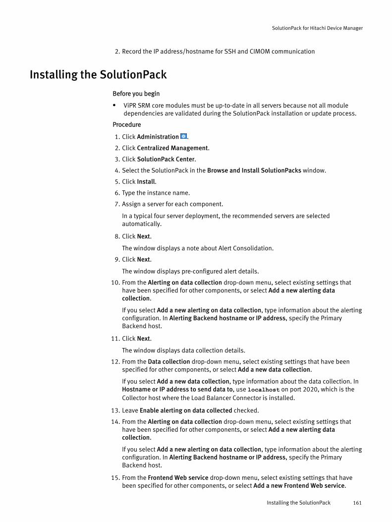
2. Record the IP address/hostname for SSH and CIMOM communication
Installing the SolutionPack
Before you begin
l ViPR SRM core modules must be up-to-date in all servers because not all moduledependencies are validated during the SolutionPack installation or update process.
Procedure
1. Click Administration .
2. Click Centralized Management.
3. Click SolutionPack Center.
4. Select the SolutionPack in the Browse and Install SolutionPacks window.
5. Click Install.
6. Type the instance name.
7. Assign a server for each component.
In a typical four server deployment, the recommended servers are selectedautomatically.
8. Click Next.
The window displays a note about Alert Consolidation.
9. Click Next.
The window displays pre-configured alert details.
10. From the Alerting on data collection drop-down menu, select existing settings thathave been specified for other components, or select Add a new alerting datacollection.
If you select Add a new alerting on data collection, type information about the alertingconfiguration. In Alerting Backend hostname or IP address, specify the PrimaryBackend host.
11. Click Next.
The window displays data collection details.
12. From the Data collection drop-down menu, select existing settings that have beenspecified for other components, or select Add a new data collection.
If you select Add a new data collection, type information about the data collection. InHostname or IP address to send data to, use localhost on port 2020, which is theCollector host where the Load Balancer Connector is installed.
13. Leave Enable alerting on data collected checked.
14. From the Alerting on data collection drop-down menu, select existing settings thathave been specified for other components, or select Add a new alerting datacollection.
If you select Add a new alerting on data collection, type information about the alertingconfiguration. In Alerting Backend hostname or IP address, specify the PrimaryBackend host.
15. From the Frontend Web service drop-down menu, select existing settings that havebeen specified for other components, or select Add a new Frontend Web service.
SolutionPack for Hitachi Device Manager
Installing the SolutionPack 161

If you select Add a new Frontend Web service, type information about the FrontendWeb service.
16. Leave Enable Topology Backend on data collected checked.
17. From the Topology Service drop-down menu, select existing settings that have beenspecified for other components, or select Add a new Topology Service.
If you select Add a new Topology service, provide information about the topologyservice and the web service. In Topology Service hostname or IP address, specify thePrimary Backend.
From the Web-Service Gateway drop-down menu, select existing settings that havebeen specified for other components, or select Add new gateway. If you select Addnew gateway, provide information about the web-service gateway where the topologyservice resides.
18. Select Enable Passive Host Discovery if you want the system to intelligently resolvehostnames from Hitachi Device Manager.
19. Select Use advanced settings to configure polling and alert settings.
20. Click Next.
The window displays reports settings.
21. In Administration Web-Service Instance, select an existing instance or create acustom instance.
22. Click Install.
23. Click Ok. Monitor the installation logs to ensure that the installation completessuccessfully.
24. Click Discovery Center > Devices Management.
25. Click Hitachi Device Manager.
These steps describe how to add hosts individually. For information about usingdiscovery groups to use the same credentials to discover multiple hosts, see Addingdevices to discovery groups on page 274.
26. Click Add new device.
27. Select the server and collector instance where you want to store the configurationdetails for this device.
28. From the HDS type drop-down menu, select Device Manager Collection, and enter aunique friendly name (such as the host or IP address) for the system. Supply the logincredentials, and specify the appropriate configuration settings. For the Array IPAddress or FQDN, enter the hostname or IP address of the Hitachi Command Suite.
29. If you want to configure Performance Collection against a specific array, selectEmbedded Performance Collection from the HDS type drop-down menu, and enter aunique friendly name (such as the host or IP address) for the system. Supply the logincredentials, and specify the appropriate configuration settings. For the Array IPAddress or FQDN enter the IP address of the array. For additional details, see Embedded Performance Collection on page 163.
30. Click Test to validate the credentials.
31. Click OK.
32. Click Save.
SolutionPack for Hitachi Device Manager
162 EMC ViPR SRM 3.7 SolutionPack Installation and Configuration Guide
Troubleshooting Device Manager collectionLearn how to troubleshoot Device Manager collection issues.
Procedure
1. Use a web browser to log in to Device Manager with http://<hitachi devicemanager IP or hostname>:<port #(example:23015)>/DeviceManagerWebService/index.jsp
2. Enter the same username and password credentials used for ViPR SRM discovery.
3. Validate that you can view all of the expected Hitachi Storage Systems under theResources tab.
Embedded Performance CollectionPerformance statistics are provided for the HUS VM, VSP, and VSP G1000 through theEmbedded SMI-S Provider.
The following components are supported:
l Storage system
l Front end port
l Volume
An SMI-S license is required, but it comes with the array for free. It must be enabled inStorage Navigator.
In Hitachi Storage Navigator, a user with the role of "Storage Administrator with view onlypermission" is required.
Enabling the SMI-S certificateLearn how to enable the SMI-S certificate on the array.
Procedure
1. Refer to the Hitachi Command Suite Administrator Guide for details.
The following chapters are related to enabling the SMI-S certificate:
l Uploading the signed certificate
l Returning the certificate to the default
Restarting the SMI-S providerLearn how to restart the SMI-S provider.
Procedure
1. Close all of the Device Manager - Storage Navigator sessions on the SVP (serviceprocessor).
2. Start the web browser.
3. In the browser on your Device Manager - Storage Navigator computer, enter thefollowing URL:
http://IP-address-or-host-name-of-SVP/cgi-bin/utility/toolpanel.cgi
SolutionPack for Hitachi Device Manager
Troubleshooting Device Manager collection 163
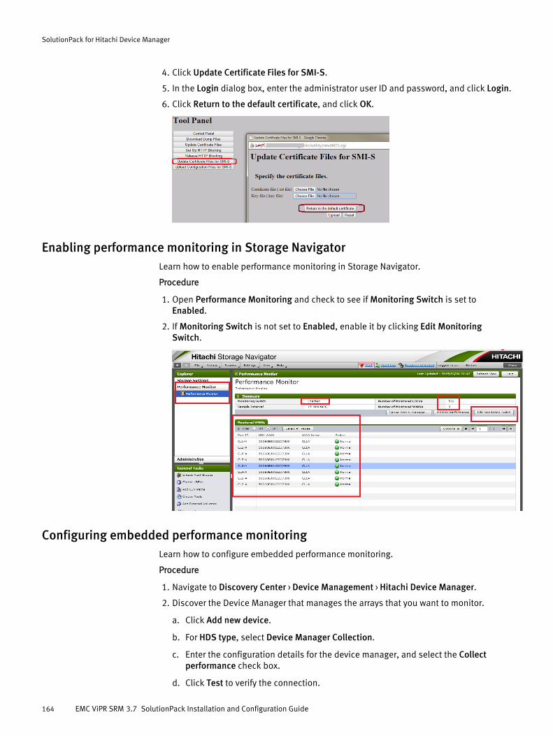
4. Click Update Certificate Files for SMI-S.
5. In the Login dialog box, enter the administrator user ID and password, and click Login.
6. Click Return to the default certificate, and click OK.
Enabling performance monitoring in Storage NavigatorLearn how to enable performance monitoring in Storage Navigator.
Procedure
1. Open Performance Monitoring and check to see if Monitoring Switch is set toEnabled.
2. If Monitoring Switch is not set to Enabled, enable it by clicking Edit MonitoringSwitch.
Configuring embedded performance monitoringLearn how to configure embedded performance monitoring.
Procedure
1. Navigate to Discovery Center > Device Management > Hitachi Device Manager.
2. Discover the Device Manager that manages the arrays that you want to monitor.
a. Click Add new device.
b. For HDS type, select Device Manager Collection.
c. Enter the configuration details for the device manager, and select the Collectperformance check box.
d. Click Test to verify the connection.
SolutionPack for Hitachi Device Manager
164 EMC ViPR SRM 3.7 SolutionPack Installation and Configuration Guide
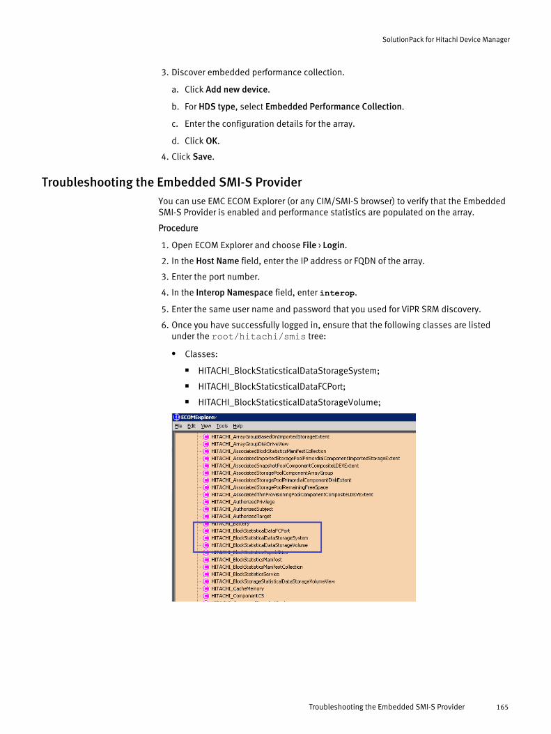
3. Discover embedded performance collection.
a. Click Add new device.
b. For HDS type, select Embedded Performance Collection.
c. Enter the configuration details for the array.
d. Click OK.
4. Click Save.
Troubleshooting the Embedded SMI-S ProviderYou can use EMC ECOM Explorer (or any CIM/SMI-S browser) to verify that the EmbeddedSMI-S Provider is enabled and performance statistics are populated on the array.
Procedure
1. Open ECOM Explorer and choose File > Login.
2. In the Host Name field, enter the IP address or FQDN of the array.
3. Enter the port number.
4. In the Interop Namespace field, enter interop.
5. Enter the same user name and password that you used for ViPR SRM discovery.
6. Once you have successfully logged in, ensure that the following classes are listedunder the root/hitachi/smis tree:
l Classes:
n HITACHI_BlockStaticsticalDataStorageSystem;
n HITACHI_BlockStaticsticalDataFCPort;
n HITACHI_BlockStaticsticalDataStorageVolume;
SolutionPack for Hitachi Device Manager
Troubleshooting the Embedded SMI-S Provider 165

Limitationsl LUNs from Hitachi AMS200 arrays do not appear in path details and end-to-end
reports.
SolutionPack for Hitachi Device Manager
166 EMC ViPR SRM 3.7 SolutionPack Installation and Configuration Guide
CHAPTER 23
SolutionPack for HP 3PAR Storeserv
l Overview............................................................................................................. 168l Preparing your system for discovery and data collection......................................168l Installing the SolutionPack..................................................................................169
SolutionPack for HP 3PAR Storeserv 167

OverviewThis SolutionPack enables you to generate real-time and historical reports and accesscapacity, performance, and inventory details about your HP 3PAR StoreServ systems.
Main reports
Hits Ratio
Reports the hits ratio distribution per subsystem as well as the hit ratio per array/controller for on all available subsystems
Inventory
Reports a summary containing the total count of all subsystems, controllers, powersupplies, ports, virtual volumes, logical disks, drive cages, and drives for allsubsystems, and reports details for these sub-components
IOPS Reports
Reports the total IOPS activities for the drives, LUNs, and ports on all availablesubsystems
Subsystems Summary
Drill-down report containing a summary of all subsystems, including key indicatorssuch as the subsystem name, version, IP address, drives, capacity, and model
TopN I/O
Reports the top 10 I/O activities for the drives, virtual volumes, and ports on allavailable subsystems
Usable Capacity
Reports the total array capacity available
Supported collection interfacesFor information about supported collection interfaces, refer to the ViPR SRM SupportMatrix.
Preparing your system for discovery and data collectionIdentify the information required to support resource discovery and data collection beforeinstalling the SolutionPack for HP 3PAR StoreServ.
ViPR SRM communicates with the HP 3PAR StoreServ system using an account with read-only privileges on the system.
Procedure
1. Identify an account with read-only privileges for the HP 3PAR StoreServ system.
2. Ensure that the array can be accessed on port 22 using SSH.
3. Ensure that the CIM server is enabled and can be accessed on the array.
SolutionPack for HP 3PAR Storeserv
168 EMC ViPR SRM 3.7 SolutionPack Installation and Configuration Guide
Installing the SolutionPackAfter you log in as an administrator, you can install a SolutionPack from CentralizedManagement.
Procedure
1. Click Administration .
2. Click Centralized Management.
3. Click SolutionPack Center.
4. Select the SolutionPack in the Browse and Install SolutionPacks window.
5. Click Install.
6. Type the instance name.
7. Assign a server for each component.
In a typical four server deployment, the recommended servers are selectedautomatically.
8. Click Next.
The windows displays alert details.
9. From the Alerting on data collection drop-down menu, select existing settings thathave been specified for other components, or select Add a new alerting datacollection.
If you select Add a new alerting on data collection, type information about the alertingconfiguration. In Alerting Backend hostname or IP address, specify the PrimaryBackend host.
10. Click Next.
The window displays data collection details.
11. From the Data collection drop-down menu, select existing settings that have beenspecified for other components, or select Add a new data collection.
If you select Add a new data collection, type information about the data collection. InHostname or IP address to send data to, use localhost on port 2020, which is theCollector host where the Load Balancer Connector is installed.
12. Leave Enable Topology Backend on data collected checked.
13. From the Topology Service drop-down menu, select existing settings that have beenspecified for other components, or select Add a new Topology Service.
If you select Add a new Topology service, provide information about the topologyservice and the web service. In Topology Service hostname or IP address, specify thePrimary Backend.
From the Web-Service Gateway drop-down menu, select existing settings that havebeen specified for other components, or select Add new gateway. If you select Addnew gateway, provide information about the web-service gateway where the topologyservice resides.
14. Select Use Advanced Settings to configure the polling interval, specify the number ofcollecting threads, or enable the collection of logical drives.
15. Click Next.
The window displays reports settings.
SolutionPack for HP 3PAR Storeserv
Installing the SolutionPack 169

16. In Administration Web-Service Instance, select an existing instance or create acustom instance.
17. Click Install.
18. Click Ok. Monitor the installation logs to ensure that the installation completessuccessfully.
19. Click Discovery Center > Devices Management.
20. Click HP 3PAR.
These steps describe how to add hosts individually. For information about usingdiscovery groups to use the same credentials to discover multiple hosts, see Addingdevices to discovery groups on page 274.
21. Click Add new device.
22. Select the server and collector instance where you want to store the configurationdetails for this device, and then enter the IP address of the array, supply the logincredentials, and specify the appropriate configuration settings.
23. Click Test to validate the credentials.
24. Click OK.
25. Click Save.
After you finish
Depending on the numbers of Storage elements managed, you may need to edit theunix-services.properties file to increase the Heap Memory to a suitable level.The file is located at: /APG/Collecting/Collector-Manager/your_instance/conf/unix-services.properties.
SolutionPack for HP 3PAR Storeserv
170 EMC ViPR SRM 3.7 SolutionPack Installation and Configuration Guide

CHAPTER 24
SolutionPack for HP EVA
l Overview............................................................................................................. 172l Preparing your HP EVA system for discovery and data collection..........................172l Installing the SolutionPack..................................................................................172
SolutionPack for HP EVA 171
OverviewThe SolutionPack for HP EVA enables you to generate real-time and historical reports andaccess capacity, performance, and inventory details about your HP EVA systems.
Main reports
Storage System dashboard
General information about the storage system
Dashboards for components
Health and performance information for storage system components
Forecast for Disk Group Utilization and Free Capacity
Reports disk group utilization and free capacity future trends
Inventory
Dashboard with aggregated information for all HP EVA storage systems
Supported collection interfacesFor information about supported collection interfaces, refer to the ViPR SRM SupportMatrix.
Preparing your HP EVA system for discovery and data collectionIdentify the information required to support resource discovery and data collection beforeinstalling the SolutionPack for HP EVA.
ViPR SRM communicates with the HP EVA Element Manager to poll information for HP EVAsystems.
Procedure
1. Identify account credentials with administrator privileges on the HP EVA ElementManager system.
2. Ensure that SMIS is configured on each of the HP EVA Management Hosts.
3. Record the IP address/hostname for CIMOM communication.
Installing the SolutionPackAfter you log in as an administrator, you can install a SolutionPack from CentralizedManagement.
Procedure
1. Click Administration .
2. Click Centralized Management.
3. Click SolutionPack Center.
4. Select the SolutionPack in the Browse and Install SolutionPacks window.
5. Click Install.
6. Type the instance name.
7. Assign a server for each component.
SolutionPack for HP EVA
172 EMC ViPR SRM 3.7 SolutionPack Installation and Configuration Guide

In a typical four server deployment, the recommended servers are selectedautomatically.
8. Click Next.
The window displays data collection details.
9. From the Data collection drop-down menu, select existing settings that have beenspecified for other components, or select Add a new data collection.
If you select Add a new data collection, type information about the data collection. InHostname or IP address to send data to, use localhost on port 2020, which is theCollector host where the Load Balancer Connector is installed.
10. Select Configure advanced settings to configure polling settings.
11. Click Next.
The window displays reports settings.
12. From the Web-Service Gateway drop-down menu, select existing settings that havebeen specified for other components, or select Add a new Web-Service Gateway.
If you select Add a new Web-Service Gateway, type information about the web-servicegateway.
13. In Administration Web-Service Instance, select an existing instance or create acustom instance.
14. Click Install.
15. Click Ok. Monitor the installation logs to ensure that the installation completessuccessfully.
16. Click Discovery Center > Devices Management.
17. Click HP EVA.
18. Click Add new device.
19. Select the server and collector instance where you want to store the configurationdetails for this device, and then enter the hostname or IP address of the host, supplythe login credentials, and specify the appropriate configuration settings.
20. Click Test to validate the credentials.
21. Click OK.
22. Click Save.
SolutionPack for HP EVA
Installing the SolutionPack 173

SolutionPack for HP EVA
174 EMC ViPR SRM 3.7 SolutionPack Installation and Configuration Guide

CHAPTER 25
SolutionPack for HP Storageworks XP
l Overview............................................................................................................. 176l Installing the SolutionPack..................................................................................176l Troubleshooting Device Manager collection........................................................ 179l Embedded Performance Collection......................................................................179
SolutionPack for HP Storageworks XP 175

OverviewThe SolutionPack for HP StorageWorks P9000 enables you to access performance,configuration data, and capacity planning data pertaining to the volumes, disks, ports,dynamically provisioned pools, and parity groups of arrays monitored by the HPStorageWorks P9000 XP software.
Main reports
Data center utilization
Capacity utilization across all HP P9000 arrays
Disk utilization
Capacity utilization across various types of disks
Storage system -> Detailed Information
Summary report containing inventory information of all HP P9000 devices:
l Parity groups
l Volumes
l Disks
l Frontend controllers
Resources
Contains various reports connected to the array
l Hosts
l Logical groups
Analytics
l Capacity Reports - Breaks down capacity across storage pool, tier, host for eachHDS array
l Performance collection troubleshooting - Helps troubleshooting performancedata collection
Note
The Shared LUNs report does not report passive hosts. Hosts discovered via switches arereported.
Supported collection interfacesFor information about supported collection interfaces, refer to the ViPR SRM SupportMatrix.
Installing the SolutionPackAfter you log in as an administrator, you can install a SolutionPack from CentralizedManagement.
Procedure
1. Click Administration .
SolutionPack for HP Storageworks XP
176 EMC ViPR SRM 3.7 SolutionPack Installation and Configuration Guide

2. Click Centralized Management.
3. Click SolutionPack Center.
4. Select the SolutionPack in the Browse and Install SolutionPacks window.
5. Click Install.
6. Type the instance name.
7. Assign a server for each component.
In a typical four server deployment, the recommended servers are selectedautomatically.
8. Click Next.
The window displays a note about Alert Consolidation.
9. Click Next.
The window displays pre-configured alert details.
10. From the Alerting on data collection drop-down menu, select existing settings thathave been specified for other components, or select Add a new alerting datacollection.
If you select Add a new alerting on data collection, type information about the alertingconfiguration. In Alerting Backend hostname or IP address, specify the PrimaryBackend host.
11. Click Next.
The window displays data collection details.
12. From the Data collection drop-down menu, select existing settings that have beenspecified for other components, or select Add a new data collection.
If you select Add a new data collection, type information about the data collection. InHostname or IP address to send data to, use localhost on port 2020, which is theCollector host where the Load Balancer Connector is installed.
13. Leave Enable alerting on data collected checked.
14. From the Alerting on data collection drop-down menu, select existing settings thathave been specified for other components, or select Add a new alerting datacollection.
If you select Add a new alerting on data collection, type information about the alertingconfiguration. In Alerting Backend hostname or IP address, specify the PrimaryBackend host.
15. From the Frontend Web service drop-down menu, select existing settings that havebeen specified for other components, or select Add a new Frontend Web service.
If you select Add a new Frontend Web service, type information about the FrontendWeb service.
16. Leave Enable Topology Backend on data collected checked.
17. From the Topology Service drop-down menu, select existing settings that have beenspecified for other components, or select Add a new Topology Service.
If you select Add a new Topology service, provide information about the topologyservice and the web service. In Topology Service hostname or IP address, specify thePrimary Backend.
From the Web-Service Gateway drop-down menu, select existing settings that havebeen specified for other components, or select Add new gateway. If you select Add
SolutionPack for HP Storageworks XP
Installing the SolutionPack 177

new gateway, provide information about the web-service gateway where the topologyservice resides.
18. In the HP StorageWorks specific configurationsection, type the host information andaccess credentials.
a. Optionally, select the Enable Secure Connection (SSL) checkbox.
If you are using a secure connection, the default port is 5989. If you are using anon-secure connection, the default is 5988.
b. Click the plus (+) sign to add more systems.
19. Select Enable Alert consolidation.
a. In Alert consolidation server hostname or IP address, select the Primary Backendhost.
b. In Alert consolidation server port number, select the port used for alertconsolidation.
20. Select Enable Passive Host Discovery if you want to intelligently resolve hostnamesfrom your HP StorageWorks systems.
21. Select Use advanced settings to configure polling and alert settings.
22. Click Next.
The window displays reports settings.
23. In Administration Web-Service Instance, select an existing instance or create acustom instance.
24. Click Install.
25. Click Ok. Monitor the installation logs to ensure that the installation completessuccessfully.
26. Click Discovery Center > Devices Management.
27. Click HP StorageWorks.
These steps describe how to add hosts individually. For information about usingdiscovery groups to use the same credentials to discover multiple hosts, see Addingdevices to discovery groups on page 274.
28. Click Add new device.
29. Select the server and collector instance where you want to store the configurationdetails for this device.
30. From the HP type drop-down menu, select Device Manager Collection, and enter aunique friendly name (such as the host or IP address) for the system. Supply the logincredentials, and specify the appropriate configuration settings. For the Array IPAddress or FQDN, enter the hostname or IP address of the HP Command View devicemanager.
31. If you want to configure Performance Collection against a specific array, selectEmbedded Performance Collection from the HP type drop-down menu, and enter aunique friendly name (such as the host or IP address) for the system. Supply the logincredentials, and specify the appropriate configuration settings. For the Array IPAddress or FQDN enter the IP address of the array. For additional details, see Embedded Performance Collection on page 179.
32. Click Test to validate the credentials.
33. Click OK.
SolutionPack for HP Storageworks XP
178 EMC ViPR SRM 3.7 SolutionPack Installation and Configuration Guide
34. Click Save.
Troubleshooting Device Manager collectionLearn how to troubleshoot Device Manager collection issues.
Procedure
1. Use a web browser to log in to HP Command View Advanced Edition Suite (CVAE):
http://<HP CVAE suite IP or hostname>:<port # (example:23015)>/DeviceManagerWebService/index.jsp
2. Enter the same username and password credentials that you used for ViPR SRMdiscovery.
3. Validate that you can view all of the expected HP Storage Systems under theResources tab.
Embedded Performance CollectionPerformance statistics are provided for the P9500 through the Embedded SMI-S Provider.
The following components are supported:
l Storage system
l Front end port
l Volume
An SMI-S license is required, but it comes with the array for free. It must be enabled inStorage Navigator.
In Storage Navigator, a user with the role of "Storage Administrator with view onlypermission" is required.
Enabling the SMI-S certificateLearn how to enable the SMI-S certificate on the array.
Procedure
1. Refer to the HP Command View Advanced Edition Administrator Guide for details.
The following chapters are related to enabling the SMI-S certificate:
l Uploading the signed certificate
l Returning the certificate to the default
Restarting the SMI-S providerLearn how to restart the SMI-S provider.
Procedure
1. Close all of the Device Manager - Storage Navigator sessions on the SVP (serviceprocessor).
2. Start the web browser.
3. In the browser on your Device Manager - Storage Navigator computer, enter thefollowing URL:
http://IP-address-or-host-name-of-SVP/cgi-bin/utility/toolpanel.cgi
SolutionPack for HP Storageworks XP
Troubleshooting Device Manager collection 179
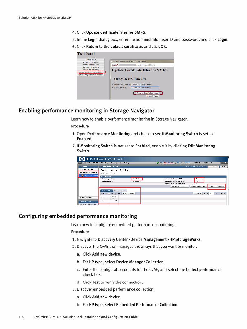
4. Click Update Certificate Files for SMI-S.
5. In the Login dialog box, enter the administrator user ID and password, and click Login.
6. Click Return to the default certificate, and click OK.
Enabling performance monitoring in Storage NavigatorLearn how to enable performance monitoring in Storage Navigator.
Procedure
1. Open Performance Monitoring and check to see if Monitoring Switch is set toEnabled.
2. If Monitoring Switch is not set to Enabled, enable it by clicking Edit MonitoringSwitch.
Configuring embedded performance monitoringLearn how to configure embedded performance monitoring.
Procedure
1. Navigate to Discovery Center > Device Management > HP StorageWorks.
2. Discover the CvAE that manages the arrays that you want to monitor.
a. Click Add new device.
b. For HP type, select Device Manager Collection.
c. Enter the configuration details for the CvAE, and select the Collect performancecheck box.
d. Click Test to verify the connection.
3. Discover embedded performance collection.
a. Click Add new device.
b. For HP type, select Embedded Performance Collection.
SolutionPack for HP Storageworks XP
180 EMC ViPR SRM 3.7 SolutionPack Installation and Configuration Guide
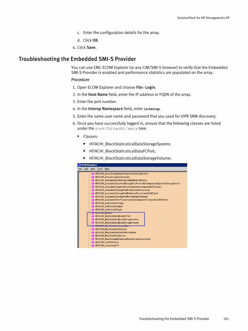
c. Enter the configuration details for the array.
d. Click OK.
4. Click Save.
Troubleshooting the Embedded SMI-S ProviderYou can use EMC ECOM Explorer (or any CIM/SMI-S browser) to verify that the EmbeddedSMI-S Provider is enabled and performance statistics are populated on the array.
Procedure
1. Open ECOM Explorer and choose File > Login.
2. In the Host Name field, enter the IP address or FQDN of the array.
3. Enter the port number.
4. In the Interop Namespace field, enter interop.
5. Enter the same user name and password that you used for ViPR SRM discovery.
6. Once you have successfully logged in, ensure that the following classes are listedunder the root/hitachi/smis tree:
l Classes:
n HITACHI_BlockStaticsticalDataStorageSystem;
n HITACHI_BlockStaticsticalDataFCPort;
n HITACHI_BlockStaticsticalDataStorageVolume;
SolutionPack for HP Storageworks XP
Troubleshooting the Embedded SMI-S Provider 181

SolutionPack for HP Storageworks XP
182 EMC ViPR SRM 3.7 SolutionPack Installation and Configuration Guide

CHAPTER 26
SolutionPack for IBM DS
l Overview............................................................................................................. 184l Preparing your IBM DS system for discovery and data collection..........................184l Installing the SolutionPack..................................................................................185
SolutionPack for IBM DS 183
OverviewThe SolutionPack for IBM DS enables you to generate real-time and historical reports andaccess capacity, performance, and inventory details about your IBM DS systems.
Main reports
IOPS
Total read and write requests per system
Throughput (/s)
Throughput of Read and Write operations for all systems
Subsystems Summary
Drill-down summary that contains key indicators such as the Controllers Ips, Drivecount, Logical Drive count, Array count, Raw Capacity, Configured Usable,Unconfigured, Free Capacity and Used Capacity for all Subsystems
Inventory
Total count of all Drives, Controllers, Logical Drives and Ports for all Subsystems
Arrays Utilization forecast
Key indicators such as Parity Group Name, Capacity, Free Capacity and UsedCapacity
Supported collection interfacesFor information about supported collection interfaces, refer to the ViPR SRM SupportMatrix.
Preparing your IBM DS system for discovery and data collectionIdentify the information required to support resource discovery and data collection beforeinstalling the SolutionPack for IBM DS.
ViPR SRM communicates with the IBM CIM/SMI-S provider that queries the storage array.
Procedure
1. Depending on your IBM DS model, do one of the following:
l IBM DS 3K/4K/5K models: Manually install and configure the IBM CIM/SMI-Sprovider on a management server.
l IBM DS 6K/8K models: The CIM/SMI-S provider is built into the HardwareManagement Console (HMC).
Note
Ensure that the CIM agent is enabled, as it was disabled by default in releasesprior to Release 4, Bundle 62.0.175.0.
2. Identify the CIM username and password used to access the array.
3. Record this information for use when you install the SolutionPack.
SolutionPack for IBM DS
184 EMC ViPR SRM 3.7 SolutionPack Installation and Configuration Guide
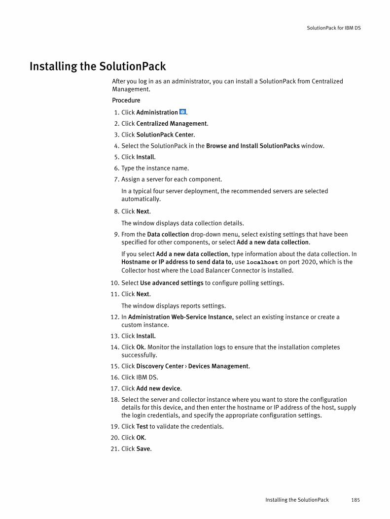
Installing the SolutionPackAfter you log in as an administrator, you can install a SolutionPack from CentralizedManagement.
Procedure
1. Click Administration .
2. Click Centralized Management.
3. Click SolutionPack Center.
4. Select the SolutionPack in the Browse and Install SolutionPacks window.
5. Click Install.
6. Type the instance name.
7. Assign a server for each component.
In a typical four server deployment, the recommended servers are selectedautomatically.
8. Click Next.
The window displays data collection details.
9. From the Data collection drop-down menu, select existing settings that have beenspecified for other components, or select Add a new data collection.
If you select Add a new data collection, type information about the data collection. InHostname or IP address to send data to, use localhost on port 2020, which is theCollector host where the Load Balancer Connector is installed.
10. Select Use advanced settings to configure polling settings.
11. Click Next.
The window displays reports settings.
12. In Administration Web-Service Instance, select an existing instance or create acustom instance.
13. Click Install.
14. Click Ok. Monitor the installation logs to ensure that the installation completessuccessfully.
15. Click Discovery Center > Devices Management.
16. Click IBM DS.
17. Click Add new device.
18. Select the server and collector instance where you want to store the configurationdetails for this device, and then enter the hostname or IP address of the host, supplythe login credentials, and specify the appropriate configuration settings.
19. Click Test to validate the credentials.
20. Click OK.
21. Click Save.
SolutionPack for IBM DS
Installing the SolutionPack 185

SolutionPack for IBM DS
186 EMC ViPR SRM 3.7 SolutionPack Installation and Configuration Guide
CHAPTER 27
SolutionPack for IBM LPAR
l Overview............................................................................................................. 188l Configuring VIO for discovery.............................................................................. 188l Verify adapter IDs in NPIV configuration.............................................................. 193l Installing the SolutionPack and configuring the devices for discovery..................193l Using Discovery Center to discover the VIO Servers and Clients........................... 194l Setting up key-based discovery for HMC..............................................................195l Using Discovery Center to discover an HMC......................................................... 195l SolutionPack Reconfiguration............................................................................. 195
SolutionPack for IBM LPAR 187
OverviewThe SolutionPack for IBM LPAR collects Inventory details about IBM's Power-Serversmanaged by Hardware Management Console (HMC) and displays the data in easy-to-usereports in ViPR SRM.
With this SolutionPack, you can generate reports to highlight key relationships in thevirtual environment such as:
l Power Systems managed by a HMC
l LPARs and VIOs residing on a Power System
l LPARs to the VIOs that provide the resource sharing capabilities for constituent LPARs
Capacity reports, such as File System Usage, help you to improve the availability ofbusiness critical applications and services by ensuring that applications have the storageresources they need to operate effectively.
Main reportsHMC Dashboard
LPAR/VIO Client Information and details
VIO Server basic details
Host Capacity Reports: Usable Capacity by FileSystem, Volume Manager Summary,Chargeable Capacity by Service Level, Disk Inventory
Topology end to end maps for VIOS/VIOC
Note
ViPR SRM Release 3.5 and earlier: Topology maps for VIOC will be reported only if therespective VIOS is discovered.
ViPR SRM Releases after 3.5: Topology maps for VIOC will be reported regardless of VIOSdiscovery.
Supported collection interfacesFor information about supported collection interfaces, refer to the ViPR SRM SupportMatrix.
Configuring VIO for discovery
The user credentials of VIO Server & VIO Clients should be configured in Discovery Center> Host Configuration.
ViPR SRM requires non-root user credentials or a SSH public/private key pair (keys can becreated for root / non-root users) to discover VIO Servers and VIO Clients.
When the VIOS Server is installed, the padmin user is automatically created and this userprovides restricted shell access. The ViPR SRM host data collection mechanism does notwork in the restricted shell environment, so you must create a non-root user andconfigure the non-root user via Sudo or PowerBroker to elevate the privileges to runcertain commands as root. Provide the non-root user credentials to ViPR SRM whilediscovering the VIO Server.
SolutionPack for IBM LPAR
188 EMC ViPR SRM 3.7 SolutionPack Installation and Configuration Guide
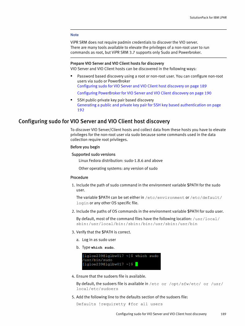
Note
ViPR SRM does not require padmin credentials to discover the VIO server.There are many tools available to elevate the privileges of a non-root user to runcommands as root, but ViPR SRM 3.7 supports only Sudo and Powerbroker.
Prepare VIO Server and VIO Client hosts for discoveryVIO Server and VIO Client hosts can be discovered in the following ways:
l Password based discovery using a root or non-root user. You can configure non-rootusers via sudo or PowerBrokerConfiguring sudo for VIO Server and VIO Client host discovery on page 189
Configuring PowerBroker for VIO Server and VIO Client discovery on page 190
l SSH public-private key pair based discoveryGenerating a public and private key pair for SSH key based authentication on page192
Configuring sudo for VIO Server and VIO Client host discoveryTo discover VIO Server/Client hosts and collect data from these hosts you have to elevateprivileges for the non-root user via sudo because some commands used in the datacollection require root privileges.
Before you begin
Supported sudo versions
Linux Fedora distribution: sudo-1.8.6 and above
Other operating systems: any version of sudo
Procedure
1. Include the path of sudo command in the environment variable $PATH for the sudouser.
The variable $PATH can be set either in /etc/environment or /etc/default/login or any other OS specific file.
2. Include the paths of OS commands in the environment variable $PATH for sudo user.
By default, most of the command files have the following location: /usr/local/sbin:/usr/local/bin:/sbin:/bin:/usr/sbin:/usr/bin
3. Verify that the $PATH is correct.
a. Log in as sudo user
b. Type which sudo.
4. Ensure that the sudoers file is available.
By default, the sudoers file is available in /etc or /opt/sfw/etc/ or /usr/local/etc/sudoers
5. Add the following line to the defaults section of the sudoers file:
Defaults !requiretty #for all users
SolutionPack for IBM LPAR
Configuring sudo for VIO Server and VIO Client host discovery 189
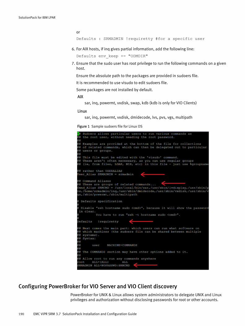
or
Defaults : SRMADMIN !requiretty #for a specific user
6. For AIX hosts, if inq gives partial information, add the following line:
Defaults env_keep += "ODMDIR"7. Ensure that the sudo user has root privilege to run the following commands on a given
host.
Ensure the absolute path to the packages are provided in sudoers file.
It is recommended to use visudo to edit sudoers file.
Some packages are not installed by default.
AIX
sar, inq, powermt, vxdisk, swap, kdb (kdb is only for VIO Clients)
Linux
sar, inq, powermt, vxdisk, dmidecode, lvs, pvs, vgs, multipath
Figure 1 Sample sudoers file for Linux OS
Configuring PowerBroker for VIO Server and VIO Client discoveryPowerBroker for UNIX & Linux allows system administrators to delegate UNIX and Linuxprivileges and authorization without disclosing passwords for root or other accounts.
SolutionPack for IBM LPAR
190 EMC ViPR SRM 3.7 SolutionPack Installation and Configuration Guide
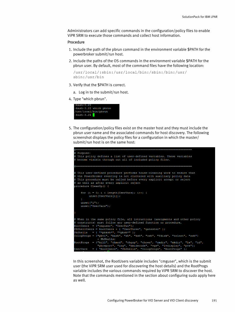
Administrators can add specific commands in the configuration/policy files to enableViPR SRM to execute those commands and collect host information.
Procedure
1. Include the path of the pbrun command in the environment variable $PATH for thepowerbroker submit/run host.
2. Include the paths of the OS commands in the environment variable $PATH for thepbrun user. By default, most of the command files have the following location:
/usr/local/:sbin:/usr/local/bin:/sbin:/bin:/usr/sbin:/usr/bin
3. Verify that the $PATH is correct.
a. Log in to the submit/run host.
4. Type "which pbrun".
5. The configuration/policy files exist on the master host and they must include thepbrun user name and the associated commands for host discovery. The followingscreenshot displays the policy files for a configuration in which the master/submit/run host is on the same host:
In this screenshot, the RootUsers variable includes "cmguser", which is the submituser (the ViPR SRM user used for discovering the host details) and the RootProgsvariable includes the various commands required by ViPR SRM to discover the host.Note that the commands mentioned in the section about configuring sudo apply hereas well.
SolutionPack for IBM LPAR
Configuring PowerBroker for VIO Server and VIO Client discovery 191

Generating a public and private key pairFor the SSH key method of discovering UNIX hosts, you must generate a valid public andprivate key pair. You can choose any key generation tool to generate a valid public andprivate key pair.
Before you begin
Before you begin host discovery, you must have a public key present on all the UNIXhosts that are to be discovered using the private key. You can create SSH keys in any Unixenvironment and import them onto the ViPR SRM collector. EMC recommends that youcreate public-private SSH keys on ViPR SRM collectors (Linux VMs) where host discoverywill be initiated.
These steps describe the procedure to generate a public and private key pair for UNIXhosts using the ssh-keygen tool.
Note
The public key is to be added to the authorized_keys file on the target hosts intended fordiscovery and the private key is to be imported to the collector VMs where discovery istriggered.
Procedure
1. A Public-Private key can be generated using the following command:
ssh-keygen -t rsa -f <location_of_the_private_key/name_of_private_key_file> -N ""For example: ssh-keygen -t rsa -f /root/.ssh/id_rsa -N ””
2. Ensure that the public and private key pair that is generated has the followingpermissions:
l chmod 600 /root/.ssh/id_rsal chmod 644 /root/.ssh/id_rsa.pub
The private key file is id_rsa.
The public key file is id_rsa.pub.
3. To make the key pair functional, append the public key to <user's homedirectory>/.ssh/authorized_keys in the target UNIX host using the commandcat <location_of_the_public_key/name_of_public_key_file> >> /<user's homedirectory>/.ssh/authorized_keysFor example: cat /root/.ssh/id_rsa.pub >> /<user's homedirectory>/.ssh/authorized_keys
Next, import the private key to the Collector used for discovery.
Importing a private key into the Collector
Procedure
1. The private key should be placed inside APG's HOME directory (where APG isinstalled).
For example: Unix: /opt/APG/
SolutionPack for IBM LPAR
192 EMC ViPR SRM 3.7 SolutionPack Installation and Configuration Guide
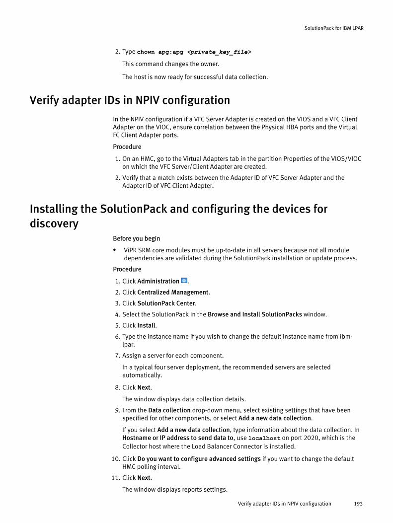
2. Type chown apg:apg <private_key_file>
This command changes the owner.
The host is now ready for successful data collection.
Verify adapter IDs in NPIV configuration
In the NPIV configuration if a VFC Server Adapter is created on the VIOS and a VFC ClientAdapter on the VIOC, ensure correlation between the Physical HBA ports and the VirtualFC Client Adapter ports.
Procedure
1. On an HMC, go to the Virtual Adapters tab in the partition Properties of the VIOS/VIOCon which the VFC Server/Client Adapter are created.
2. Verify that a match exists between the Adapter ID of VFC Server Adapter and theAdapter ID of VFC Client Adapter.
Installing the SolutionPack and configuring the devices fordiscovery
Before you begin
l ViPR SRM core modules must be up-to-date in all servers because not all moduledependencies are validated during the SolutionPack installation or update process.
Procedure
1. Click Administration .
2. Click Centralized Management.
3. Click SolutionPack Center.
4. Select the SolutionPack in the Browse and Install SolutionPacks window.
5. Click Install.
6. Type the instance name if you wish to change the default instance name from ibm-lpar.
7. Assign a server for each component.
In a typical four server deployment, the recommended servers are selectedautomatically.
8. Click Next.
The window displays data collection details.
9. From the Data collection drop-down menu, select existing settings that have beenspecified for other components, or select Add a new data collection.
If you select Add a new data collection, type information about the data collection. InHostname or IP address to send data to, use localhost on port 2020, which is theCollector host where the Load Balancer Connector is installed.
10. Click Do you want to configure advanced settings if you want to change the defaultHMC polling interval.
11. Click Next.
The window displays reports settings.
SolutionPack for IBM LPAR
Verify adapter IDs in NPIV configuration 193
12. In Administration Web-Service Instance, select an existing instance or create acustom instance.
13. Click Install.
14. Click Ok. Monitor the installation logs to ensure that the installation completessuccessfully.
15. Click Discovery Center > Devices Management.
16. Click IBM LPAR.
17. Click Add new device.
18. Select the server and collector instance where you want to store the configurationdetails for this device, and then enter the hostname or IP address of the host, supplythe login credentials, and specify the appropriate configuration settings.
19. Click Test to validate the credentials.
20. Click OK.
21. Click Save.
Results
The SolutionPack for Physical Hosts will collect data from Physical Host/LPAR/VIOServers. You can configure script block from SolutionPack for Physical Hosts on multiplecollector VMs where you intend to discover hosts/LPAR/VIO server. Based on yourdeployment plan, you can distribute host discovery on multiple collector VMs.
Using Discovery Center to discover the VIO Servers and ClientsProcedure
1. From the User Interface, click Administration .
2. Click Discovery Center.
3. Under Device Type, click Host configuration.
4. Click Add new device.
5. In Server, select the collector VM where script block from SolutionPack for PhysicalHosts is installed.
6. Enter the VIO Server/Client configuration details and click Ok.
7. Add a new device for each VIO Server and Client that will be discovered.
8. Select the Authentication Type as:
Option Description
Password based Authenticates with password.
Public key based Authenticates with SSH public private key.
9. Provide username (root or non-root user):
a. Provide the password of the host for password based authentication
b. Provide the location of the private key for public key based authentication( /opt/APG/<Name of private key>)
10. Click Ok.
11. Select the device added and click Save.
SolutionPack for IBM LPAR
194 EMC ViPR SRM 3.7 SolutionPack Installation and Configuration Guide
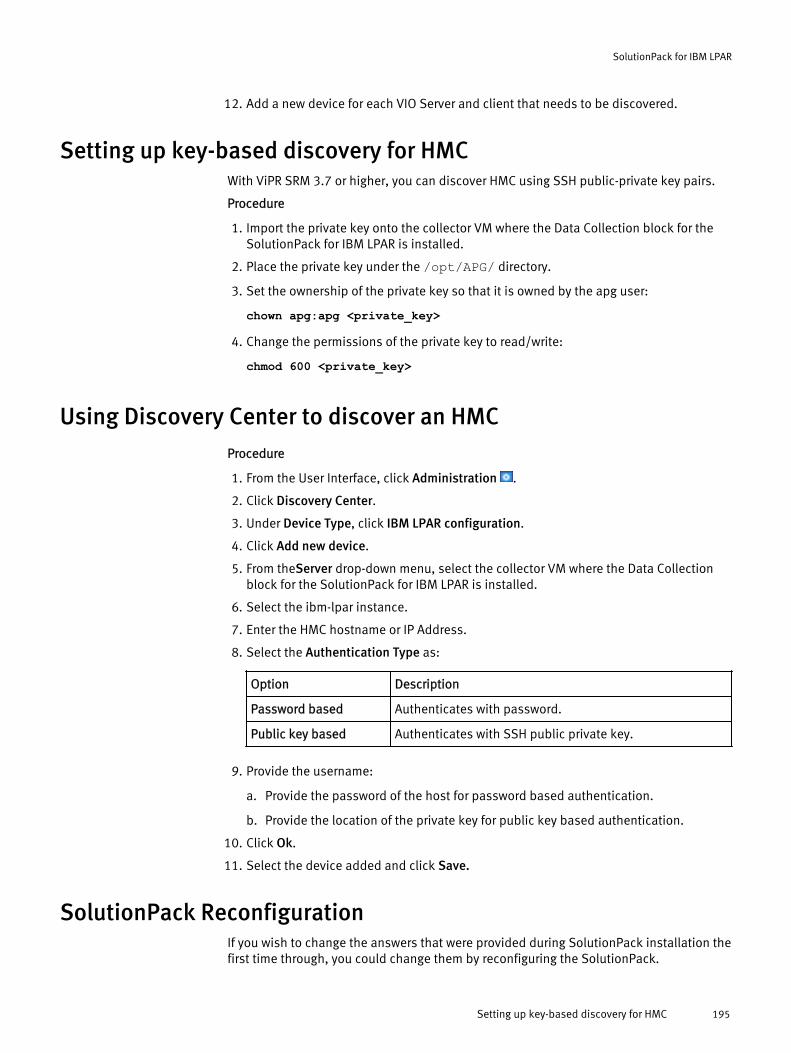
12. Add a new device for each VIO Server and client that needs to be discovered.
Setting up key-based discovery for HMCWith ViPR SRM 3.7 or higher, you can discover HMC using SSH public-private key pairs.
Procedure
1. Import the private key onto the collector VM where the Data Collection block for theSolutionPack for IBM LPAR is installed.
2. Place the private key under the /opt/APG/ directory.
3. Set the ownership of the private key so that it is owned by the apg user:
chown apg:apg <private_key>
4. Change the permissions of the private key to read/write:
chmod 600 <private_key>
Using Discovery Center to discover an HMCProcedure
1. From the User Interface, click Administration .
2. Click Discovery Center.
3. Under Device Type, click IBM LPAR configuration.
4. Click Add new device.
5. From theServer drop-down menu, select the collector VM where the Data Collectionblock for the SolutionPack for IBM LPAR is installed.
6. Select the ibm-lpar instance.
7. Enter the HMC hostname or IP Address.
8. Select the Authentication Type as:
Option Description
Password based Authenticates with password.
Public key based Authenticates with SSH public private key.
9. Provide the username:
a. Provide the password of the host for password based authentication.
b. Provide the location of the private key for public key based authentication.
10. Click Ok.
11. Select the device added and click Save.
SolutionPack ReconfigurationIf you wish to change the answers that were provided during SolutionPack installation thefirst time through, you could change them by reconfiguring the SolutionPack.
SolutionPack for IBM LPAR
Setting up key-based discovery for HMC 195

Procedure
1. Click Administration .
2. Under Centralized Management.
a. Click SolutionPacks > Other Components and select generic-rsc.
The SolutionPack Reconfiguration dialog box appears.
b. Click SolutionPacks > Infrastructure > IBM LPAR and select the instance for LPAR.
3. Change the configuration as desired.
4. Click Reconfigure.
SolutionPack for IBM LPAR
196 EMC ViPR SRM 3.7 SolutionPack Installation and Configuration Guide
CHAPTER 28
SolutionPack for IBM SAN Volume Controller/Storwize
l Overview............................................................................................................. 198l Preparing for discovery and data collection......................................................... 198l Installing the SolutionPack..................................................................................199l Limitations..........................................................................................................200
SolutionPack for IBM SAN Volume Controller/Storwize 197

OverviewThe IBM System Storage SAN Volume Controller (SVC) is a member of the IBM Storwizefamily, which provides storage virtualization with a single point of control for storageresources.
The SolutionPack for IBM SAN Volume Controller/Storwize enables you to generate real-time and historical reports and access capacity and performance details to gain insightinto the management of the underlying Storwize storage environment.
Main reports
Virtual Storage Dashboard
Drill-down report that provides details about virtual storage information of the VirtualDisks such as Configured Usable, Virtual Disks Usable, Virtual Disks Unused, VirtualVolume Usable, Virtual Volume Used, and Virtual Volume Free.
Clusters
Drill-down report that provides details about each cluster such as cluster nodes,virtual volumes, virtual disks, quorum disks, virtual pools, host association, pathdetails, and connectivity.
Performance Reports
Drill-down report that provides details about read and write requests, read and writethroughput on Virtual Disks, and Virtual Volumes for all SVC Clusters.
Capacity Reports
Drill-down report that provides a further breakdown of aggregated capacities such asConfigured Usable, Virtual Disks Usable, Virtual Disks Unused, Virtual VolumeUsable, Virtual Volume Used, Virtual Volume Free, and Usable Capacity by Pools.
Port Inventory
Drill-down report that provides details of ports per cluster node such as portconnectivity, speed, and availability.
Inactive Devices and Components
Drill-down report that provides details of devices and components which have notbeen recently discovered.
Supported collection interfacesFor information about supported collection interfaces, refer to the ViPR SRM SupportMatrix.
Preparing for discovery and data collectionIdentify the information required to support resource discovery and data collection beforeinstalling the SolutionPack for IBM SAN Volume Controller/Storwize .
Before you begin
l Confirm that the IBM SVC model and version are supported.
l ViPR SRM core modules must be up-to-date on all servers because not all moduledependencies are validated during the SolutionPack installation or update process.
l An SMI-S provider must be running on the IBM SVC server on port 5989.
SolutionPack for IBM SAN Volume Controller/Storwize
198 EMC ViPR SRM 3.7 SolutionPack Installation and Configuration Guide
Procedure
1. Record the IBM SVC/Storwize cluster IP address and hostname (for SSH and CIMOMcommunication).
2. Record the username and password for the cluster.
Note: All performance, topology, and capacity metrics are supported for users who aremembers of the "Administrator" or "SecurityAdmin" user group. Performance data(such as CPU usage and port traffic statistics of non-configuration nodes) are notsupported for users who are members of the "Service" or "CopyOperator" or "Monitor"user groups.
Installing the SolutionPackAfter you log in as an administrator, you can install a SolutionPack from CentralizedManagement.
Procedure
1. Click Administration .
2. Click Centralized Management.
3. Click SolutionPack Center.
4. Select the SolutionPack in the Browse and Install SolutionPacks window.
5. Click Install.
6. Type the instance name.
7. Assign a server for each component.
In a typical four server deployment, the recommended servers are selectedautomatically.
8. Click Next.
The window displays pre-configured alert details.
9. From the Alerting on data collection drop-down menu, select existing settings thathave been specified for other components, or select Add a new alerting datacollection.
If you select Add a new alerting on data collection, type information about the alertingconfiguration. In Alerting Backend hostname or IP address, specify the PrimaryBackend host.
10. Click Next.
The window displays data collection details.
11. From the Data collection drop-down menu, select existing settings that have beenspecified for other components, or select Add a new data collection.
If you select Add a new data collection, type information about the data collection. InHostname or IP address to send data to, use localhost on port 2020, which is theCollector host where the Load Balancer Connector is installed.
12. Leave Enable Topology Backend on data collected checked.
13. From the Topology Service drop-down menu, select existing settings that have beenspecified for other components, or select Add a new Topology Service.
If you select Add a new Topology service, provide information about the topologyservice and the web service. In Topology Service hostname or IP address, specify thePrimary Backend.
SolutionPack for IBM SAN Volume Controller/Storwize
Installing the SolutionPack 199
From the Web-Service Gateway drop-down menu, select existing settings that havebeen specified for other components, or select Add new gateway. If you select Addnew gateway, provide information about the web-service gateway where the topologyservice resides.
14. Select Use advanced settings to configure polling settings.
15. Click Next.
The window displays reports settings.
16. In Administration Web-Service Instance, select an existing instance or create acustom instance.
17. Click Install.
18. Click Ok. Monitor the installation logs to ensure that the installation completessuccessfully.
19. Click Discovery Center > Devices Management.
20. Click IBM SAN Volume Controller/Storwize.
21. Click Add new device.
22. Select the server and collector instance where you want to store the configurationdetails for this device, and then enter the hostname or IP address of the host, supplythe login credentials, and specify the appropriate configuration settings.
23. Leave Enable performance synchronization checked.
Enable performance synchronization allows ViPR SRM to collect and reportperformance statistics across all of the nodes. The performance statistics files arecopied from the non-config nodes to the config node, and the copied files are purgedafter they are processed. None of the original performance statistics on any node arepurged. Disabling performance synchronization will allow collection and reportingonly on the config node.
24. Click Test to validate the credentials.
25. Click OK.
26. Click Save.
Limitationsl Back end arrays IBM DS, HDS, HPXP, and XtremeIO are not supported.
l Internal Storage is not supported in the Raw Capacity Usage and Configured Usablereports. Service Level and Chargeback is not supported for mdisks (virtual disks)based on internal storage.
l Replication is not supported.
SolutionPack for IBM SAN Volume Controller/Storwize
200 EMC ViPR SRM 3.7 SolutionPack Installation and Configuration Guide
CHAPTER 29
SolutionPack for IBM XIV
l Overview............................................................................................................. 202l Preparing your IBM XIV system for discovery and data collection......................... 202l Installing the SolutionPack..................................................................................203l Limitations..........................................................................................................204l Known problems ................................................................................................ 205
SolutionPack for IBM XIV 201
OverviewThe SolutionPack for IBM XIV enables you to monitor the status and performance of yourIBM XIV disk storage system, and access performance and configuration data pertainingto the volumes, disks, pools and ports of IBM XIV systems.
Main reports
Volumes IOPS
Reports the read and write requests over time for all XIV systems
ReadRequests
Reports the read requests over time for all XIV systems
WriteRequests
Reports the write requests over time for all XIV systems
Volumes Throughput (/s)
Reports the volumes read and write throughput over time for all XIV systems
ReadThroughput
Reports the volumes read throughput over time for all XIV systems
WriteThroughput
Reports the volumes write throughput over time for all XIV systems
Systems detailed per array capacity and performance reports
Reports capacity and performance per array.
Supported collection interfacesFor information about supported collection interfaces, refer to the ViPR SRM SupportMatrix.
Preparing your IBM XIV system for discovery and data collectionIdentify the information required to support resource discovery and data collection beforeinstalling the SolutionPack for IBM XIV.
ViPR SRM communicates with IBM XIV using the CIM agent.
Procedure
1. Ensure that the CIM agent is installed.
Starting with IBM XIV Storage System V10.1.0, the CIM agent is pre-installed on theadministrative module. The embedded CIM agent is automatically enabled andpreconfigured.
2. Identify the access credentials.
3. Record this information for use when you install the SolutionPack.
SolutionPack for IBM XIV
202 EMC ViPR SRM 3.7 SolutionPack Installation and Configuration Guide
Installing the SolutionPackAfter you log in as an administrator, you can install a SolutionPack from CentralizedManagement.
Procedure
1. Click Administration .
2. Click Centralized Management.
3. Click SolutionPack Center.
4. Select the SolutionPack in the Browse and Install SolutionPacks window.
5. Click Install.
6. Type the instance name.
7. Assign a server for each component.
In a typical four server deployment, the recommended servers are selectedautomatically.
8. Click Next.
The window displays a note about Alert Consolidation.
9. Click Next.
The window displays pre-configured alert details.
10. From the Alerting on data collection drop-down menu, select existing settings thathave been specified for other components, or select Add a new alerting datacollection.
If you select Add a new alerting on data collection, type information about the alertingconfiguration. In Alerting Backend hostname or IP address, specify the PrimaryBackend host.
11. Click Next.
The window displays data collection details.
12. From the Data collection drop-down menu, select existing settings that have beenspecified for other components, or select Add a new data collection.
If you select Add a new data collection, type information about the data collection. InHostname or IP address to send data to, use localhost on port 2020, which is theCollector host where the Load Balancer Connector is installed.
13. Leave Enable Topology Backend on data collected checked.
14. From the Topology Service drop-down menu, select existing settings that have beenspecified for other components, or select Add a new Topology Service.
If you select Add a new Topology service, provide information about the topologyservice and the web service. In Topology Service hostname or IP address, specify thePrimary Backend.
From the Web-Service Gateway drop-down menu, select existing settings that havebeen specified for other components, or select Add new gateway. If you select Addnew gateway, provide information about the web-service gateway where the topologyservice resides.
15. Select Configure advanced settings to configure polling settings.
SolutionPack for IBM XIV
Installing the SolutionPack 203

16. Click Next.
The window displays reports settings.
17. In Administration Web-Service Instance, select an existing instance or create acustom instance.
18. Click Install.
19. Click Ok. Monitor the installation logs to ensure that the installation completessuccessfully.
20. Click Discovery Center > Devices Management.
21. Click IBM XIV.
These steps describe how to add hosts individually. For information about usingdiscovery groups to use the same credentials to discover multiple hosts, see Addingdevices to discovery groups on page 274.
22. Click Add new device.
23. Select the server and collector instance where you want to store the configurationdetails for this device, and then enter the hostname or IP address of the host, supplythe login credentials, and specify the appropriate configuration settings.
24. Click Test to validate the credentials.
25. Click OK.
26. Click Save.
LimitationsDiscovery of LDAP users requires active GUI sessionDue to limitations in the IBM software, discovery using the LDAP users account will notsucceed unless there is an active IBM XIV GUI user session. The session must be activeeither for the corresponding LDAP user or for a storage administrator.
Max Storage Volume Response Time metric not collectedThe SolutionPack does not collect the Max Storage Volume Response Time (ms) metricneeded for the All > Explore > Hosts > [host] > Device Summary > [host] report.
No support for Used for File, LUN alias, and Replica 2 and Replica 3 details‘Used for File’ metrics are not supported. Therefore, the respective columns in thefollowing reports will be empty.
l All > Dashboards > Storage > Enterprise Capacity Dashboard > Usable Capacity by Pool
l All > Dashboards > Storage > Chargeback by Group
l All > Explore > Storage > More Reports > Storage Pools
‘LUN Alias’ column is empty in the following report:
l All > Explore > Storage > More Reports > More Storage Inventories > All LUNs
Remote replication data is not exposed through the SMI provider; therefore, Replica 2and Replica 3 columns details will be empty in the following report:
l All > Explore > Storage > More Reports > More Storage Inventories > Replication
SolutionPack for IBM XIV
204 EMC ViPR SRM 3.7 SolutionPack Installation and Configuration Guide

Known problemsTable 7 Known problems
Issue number Problem description Workaround/Resolution
SRS-11244EMP-2943
After updating to 3.6, the Discovery Center is unable toimport the device details.
You can add a third column "friendly name" in theexported CSV file and give the serial number of XIVarray (for backward compatibility) as friendly name foreach instance of an XIV system. Then import themodified CSV file in to the updated Discovery Center.
SRS-11095(Doc)
In the report All->Explore->Storage->More Reports->Enterprise Capacity, the "Used for HDFS (GB)" and"Used For Object (GB)" columns have no capacity data.
There is no workaround at this time.
SRS-9925 After updating from version 3.5 or earlier to version 3.6,if you provide a random user-friendly name for the XIVarray, historic data will not be displayed.
After the update, from the Discovery Center, update the"Unique friendly name for the XIV system" field with thearray's serial number. For example, if the IBM XIV arrayserial number is 9825369, change the "Unique friendlyname for the XIV system" field to "XIV 9825369."
SolutionPack for IBM XIV
Known problems 205

SolutionPack for IBM XIV
206 EMC ViPR SRM 3.7 SolutionPack Installation and Configuration Guide

CHAPTER 30
SolutionPack for Microsoft Hyper-V
l Overview............................................................................................................. 208l Configuring credentials for SolutionPack for Microsoft Hyper-V............................208l Requirements for data collection.........................................................................208l Installing the SolutionPack..................................................................................209l Using a test script to query WMI objects.............................................................. 210
SolutionPack for Microsoft Hyper-V 207
OverviewThe SolutionPack for Microsoft Hyper-V generates real-time and historical reports so youunderstand Hyper-V performance through global and detailed status of Hyper-V hostsand underlying virtual machines.
Main reports
Inventory
Displays the inventory of devices, parts and metrics from Hypervisors and VirtualMachines
Virtual Disk Use Analysis
Tool to analyze the utilization profile of Virtual Hard Disk images
All Hosts | All Virtual Machines
Displays all available performance graphs for Hypervisors and Virtual Machines
Global Status
Shows the global status of all hosts and running virtual machines in theenvironment, detailed by component type
SLA Detailled View
Shows the current and forecasted SLA values for Hypervisors and Virtual Machines
Virtual Machines Running On Snapshot Disks
Shows all virtual machines running on snapshot disks. They impact diskperformance and impact storage performance when it is time to commit changes onthe original virtual disk.
Configuring credentials for SolutionPack for Microsoft Hyper-Vl Hyper-V Collector Manager must have the right to query WMI objects from Hyper-V
hosts
l PowerShell must allow the execution of unassigned PowerShell scripts
Requirements for data collection
In order to collect data from Microsoft Hyper-V hosts, the environment needs to meet thefollowing requirements:
l The Collect SolutionPack Block must be installed in a server using Windows Server2008 R2 Service Pack 1 or later.
l The Collect SolutionPack Block must be able to query WMI objects in remoteMicrosoft Hyper-V hosts.
l The Collect SolutionPack Block machine must allow the execution of unsignedPowerShell scripts. To provide this capability, run the following command as anadministrative user: PowerShell -C Set-ExecutionPolicy Unrestricted.
SolutionPack for Microsoft Hyper-V
208 EMC ViPR SRM 3.7 SolutionPack Installation and Configuration Guide
Installing the SolutionPack
Before you begin
l Core modules must be up-to-date in all servers because not all module dependenciesare validated during the SolutionPack installation or update process.
Procedure
1. Click Administration .
2. Click Centralized Management.
3. Click SolutionPack Center.
4. Select the SolutionPack in the Browse and Install SolutionPacks window.
5. Click Install.
6. Type the instance name.
7. Assign a server for each component.
In a typical four server deployment, the recommended servers are selectedautomatically.
8. Click Next.
The window displays data collection details.
9. From the Data collection drop-down menu, select existing settings that have beenspecified for other components, or select Add a new data collection.
If you select Add a new data collection, type information about the data collection. InHostname or IP address to send data to, use localhost on port 2020, which is theCollector host where the Load Balancer Connector is installed.
10. Click Next.
The window displays reports settings.
11. In Administration Web-Service Instance, select an existing instance or create acustom instance.
12. Click Install.
13. Click Ok. Monitor the installation logs to ensure that the installation completessuccessfully.
14. Click Discovery Center > Devices Management.
15. Click Microsoft Hyper-V.
16. Click Add new device.
17. Select the server and collector instance where you want to store the configurationdetails for this device, and then enter the hostname or IP address of the host, supplythe login credentials, and specify the appropriate configuration settings.
Clicking the Test button results in a warning message that can be ignored.
18. Click OK.
19. Click Save.
SolutionPack for Microsoft Hyper-V
Installing the SolutionPack 209
Using a test script to query WMI objects
The Test feature located in the Discovery Center under the Centralized Management UI isnot supported for the SolutionPack for Microsoft Hyper-V. Instead, use the test methodpresented in this topic.The SolutionPack for Microsoft Hyper-V provides a script that can be used to check if ispossible to query all required WMI objects using the provided user. The script is in thefolder <APG_FOLDER>/Collecting/XML-Collector/<SolutionPack_instance_name>/conf/. You must execute the script from theCollect SolutionPack Block machine. Use the following syntax to run the script:
TestWMI.ps1 -Computer <ip-or-hostname> -Username <domain-or-machine\username> -Password <password> [-NoPing]
-ComputerRemote Hyper-V host IP address or hostname
-UsernameUsername used to perform remote WMI queries, in the format DOMAIN\username fordomain users or MACHINE\username for local users
-PasswordPassword of the user specified with the -Username parameter
-NoPing(optional) If the remote Hyper-V host is blocking ping requests, you must use thisparameter to skip connectivity tests
SolutionPack for Microsoft Hyper-V
210 EMC ViPR SRM 3.7 SolutionPack Installation and Configuration Guide
CHAPTER 31
SolutionPack for Microsoft SQL Server
l Overview............................................................................................................. 212l User privilege requirements for SolutionPack for Microsoft SQL...........................212l Configuring the SolutionPack with an unprivileged account.................................213l Installing the SolutionPack for Microsoft SQL...................................................... 214l Limitations for Microsoft SQL Server....................................................................215
SolutionPack for Microsoft SQL Server 211
OverviewThis SolutionPack includes reports for unified monitoring of Microsoft SQL Database(s)using SQL queries against targeted servers. The reports give key information on status,performance and availability of databases, datafile capacities, and performance metricssuch as Index, IO, Wait, and Memory pressure.
SQL commandsThis SolutionPack uses these commands:
l SELECT
l CONNECT
l INSERT
l CREATE TABLE
n This creates temporary tables used when gathering the capacity-relatedinformation of databases. The temporary tables are created in the tempdb table.These tables are later dropped.
l EXEC
n Executes a stored procedure that lists disks and their available free space.
l DROP
n Removes temporary tables created earlier in the tempdb table.
Main reports
l Instance Sizes
l SQL Server Instances Overview
n This includes reports for database sizes, database overview, and performanceKPIs such as configuration parameters, IO, access methods, buffer manager,general statistics, and memory manager.
l Inventory of servers, instances, databases, and data/log files
l Situations to Watch
n This includes index fragmentation, data/log files out of space, inactive devicesand components, and actual and forecasted SLA values.
l SQL Server to SAN Inventory
n Lists capacity reports per SQL Server instance
User privilege requirements for SolutionPack for Microsoft SQLThe Microsoft SQL Server can be discovered with SQL Authentication or WindowsAuthentication.
Microsoft SQL authenticationSQL authentication works for users having either SYSADMIN privileges or an unprivilegedaccount.
SolutionPack for Microsoft SQL Server
212 EMC ViPR SRM 3.7 SolutionPack Installation and Configuration Guide
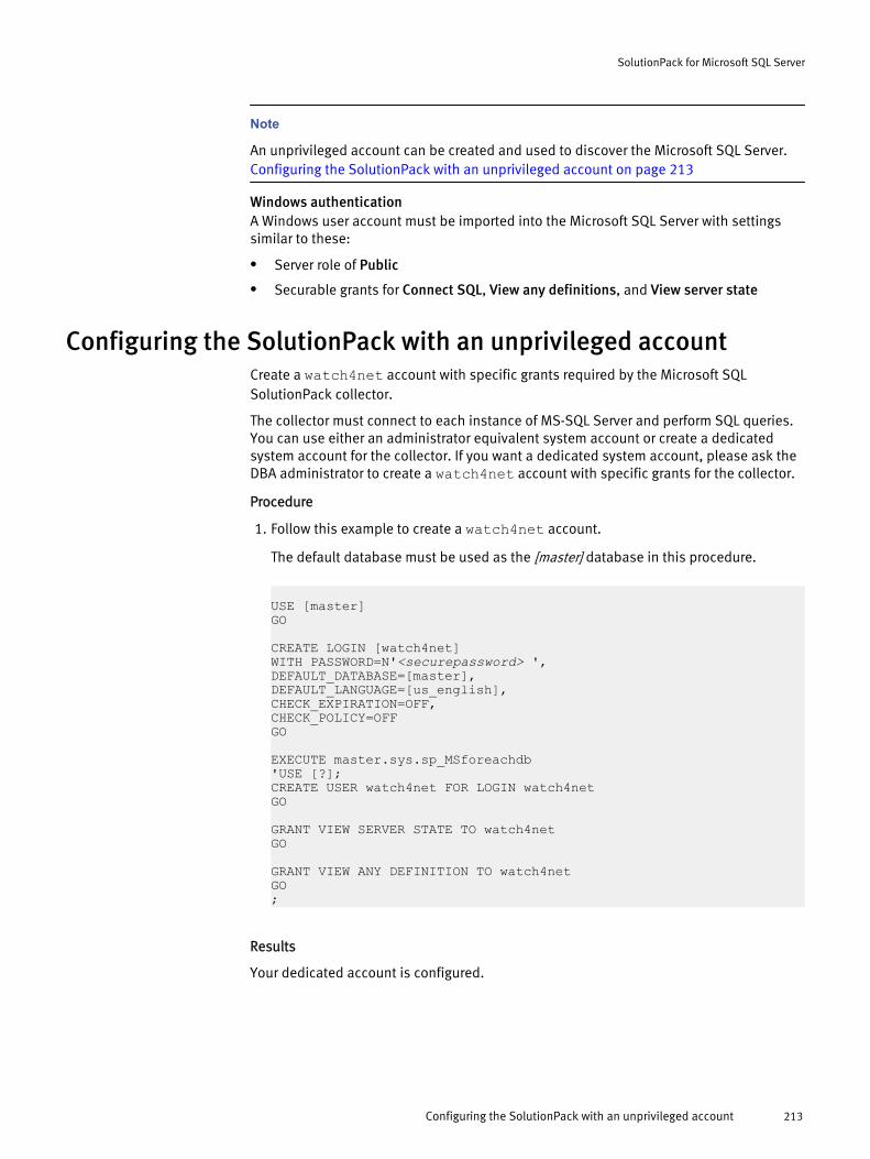
Note
An unprivileged account can be created and used to discover the Microsoft SQL Server. Configuring the SolutionPack with an unprivileged account on page 213
Windows authenticationA Windows user account must be imported into the Microsoft SQL Server with settingssimilar to these:
l Server role of Public
l Securable grants for Connect SQL, View any definitions, and View server state
Configuring the SolutionPack with an unprivileged accountCreate a watch4net account with specific grants required by the Microsoft SQLSolutionPack collector.
The collector must connect to each instance of MS-SQL Server and perform SQL queries.You can use either an administrator equivalent system account or create a dedicatedsystem account for the collector. If you want a dedicated system account, please ask theDBA administrator to create a watch4net account with specific grants for the collector.
Procedure
1. Follow this example to create a watch4net account.
The default database must be used as the [master] database in this procedure.
USE [master]GO
CREATE LOGIN [watch4net]WITH PASSWORD=N'<securepassword> ',DEFAULT_DATABASE=[master],DEFAULT_LANGUAGE=[us_english],CHECK_EXPIRATION=OFF,CHECK_POLICY=OFFGO
EXECUTE master.sys.sp_MSforeachdb'USE [?];CREATE USER watch4net FOR LOGIN watch4netGO
GRANT VIEW SERVER STATE TO watch4netGO
GRANT VIEW ANY DEFINITION TO watch4netGO;
Results
Your dedicated account is configured.
SolutionPack for Microsoft SQL Server
Configuring the SolutionPack with an unprivileged account 213
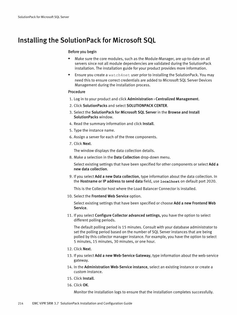
Installing the SolutionPack for Microsoft SQL
Before you begin
l Make sure the core modules, such as the Module-Manager, are up-to-date on allservers since not all module dependencies are validated during the SolutionPackinstallation. The installation guide for your product provides more information.
l Ensure you create a watch4net user prior to installing the SolutionPack. You mayneed this to ensure correct credentials are added to Microsoft SQL Server DevicesManagement during the installation process.
Procedure
1. Log in to your product and click Administration > Centralized Management.
2. Click SolutionPacks and select SOLUTIONPACK CENTER.
3. Select the SolutionPack for Microsoft SQL Server in the Browse and InstallSolutionPacks window.
4. Read the summary information and click Install.
5. Type the instance name.
6. Assign a server for each of the three components.
7. Click Next.
The window displays the data collection details.
8. Make a selection in the Data Collection drop-down menu.
Select existing settings that have been specified for other components or select Add anew data collection.
9. If you select Add a new Data collection, type information about the data collection. Inthe Hostname or IP address to send data field, use localhost on default port 2020.
This is the Collector host where the Load Balancer Connector is installed.
10. Select the Frontend Web Service option.
Select existing settings that have been specified or choose Add a new Frontend WebService.
11. If you select Configure Collector advanced settings, you have the option to selectdifferent polling periods.
The default polling period is 15 minutes. Consult with your database administrator toset the polling period based on the number of SQL Server instances that are beingpolled by this collector manager instance. For example, you have the option to select5 minutes, 15 minutes, 30 minutes, or one hour.
12. Click Next.
13. If you select Add a new Web-Service Gateway, type information about the web-servicegateway.
14. In the Administration Web-Service instance, select an existing instance or create acustom instance.
15. Click Install.
16. Click OK.
Monitor the installation logs to ensure that the installation completes successfully.
SolutionPack for Microsoft SQL Server
214 EMC ViPR SRM 3.7 SolutionPack Installation and Configuration Guide
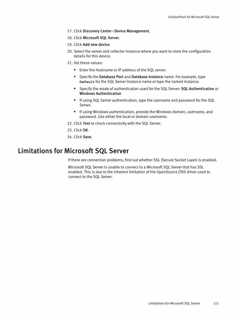
17. Click Discovery Center > Device Management.
18. Click Microsoft SQL Server.
19. Click Add new device.
20. Select the server and collector instance where you want to store the configurationdetails for this device.
21. Set these values:
l Enter the Hostname or IP address of the SQL server.
l Specify the Database Port and Database Instance name. For example, typeDefault for the SQL Server Instance name or type the named instance.
l Specify the mode of authentication used for the SQL Server: SQL Authentication orWindows Authentication
l If using SQL Server authentication, type the username and password for the SQLServer.
l If using Windows authentication, provide the Windows domain, username, andpassword. Use either the local or domain username.
22. Click Test to check connectivity with the SQL Server.
23. Click OK.
24. Click Save.
Limitations for Microsoft SQL ServerIf there are connection problems, find out whether SSL (Secure Socket Layer) is enabled.
Microsoft SQL Server is unable to connect to a Microsoft SQL Server that has SSLenabled. This is due to the inherent limitation of the OpenSource JTDS driver used toconnect to the SQL Server.
SolutionPack for Microsoft SQL Server
Limitations for Microsoft SQL Server 215

SolutionPack for Microsoft SQL Server
216 EMC ViPR SRM 3.7 SolutionPack Installation and Configuration Guide

CHAPTER 32
SolutionPack for NetApp Filer
l Overview............................................................................................................. 218l Configuring access credentials............................................................................218l Preparing NetApp Filer for discovery and data collection......................................219l Installing the SolutionPack..................................................................................219l Supported use cases and limitations...................................................................220
SolutionPack for NetApp Filer 217
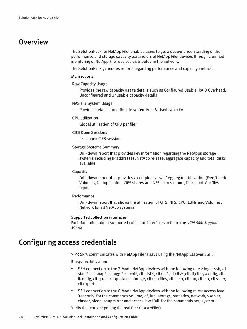
OverviewThe SolutionPack for NetApp Filer enables users to get a deeper understanding of theperformance and storage capacity parameters of NetApp Filer devices through a unifiedmonitoring of NetApp Filer devices distributed in the network.
The SolutionPack generates reports regarding performance and capacity metrics.
Main reports
Raw Capacity Usage
Provides the raw capacity usage details such as Configured Usable, RAID Overhead,Unconfigured and Unusable capacity details
NAS File System Usage
Provides details about the file system Free & Used capacity
CPU utilization
Global utilization of CPU per filer
CIFS Open Sessions
Lists open CIFS sessions
Storage Systems Summary
Drill-down report that provides key information regarding the NetApps storagesystems including IP addresses, NetApp release, aggregate capacity and total disksavailable
Capacity
Drill-down report that provides a complete view of Aggregate Utilization (Free/Used)Volumes, Deduplication, CIFS shares and NFS shares report, Disks and Maxfilesreport
Performance
Drill-down report that shows the utilization of CIFS, NFS, CPU, LUNs and Volumes,Network for all NetApp systems
Supported collection interfacesFor information about supported collection interfaces, refer to the ViPR SRM SupportMatrix.
Configuring access credentials
ViPR SRM communicates with NetApp Filer arrays using the NetApp CLI over SSH.
It requires following:
l SSH connection to the 7-Mode NetApp devices with the following roles: login-ssh, cli-stats*, cli-snap*, cli-aggr*,cli-vol*, cli-disk*, cli-nfs*,cli-cifs* ,cli-df,cli-sysconfig, cli-ifconfig, cli-qtree, cli-quota,cli-storage, cli-maxfiles, cli-echo, cli-lun, cli-fcp, cli-vfiler,cli-exportfs
l SSH connection to the C-Mode NetApp devices with the following roles: access level'readonly' for the commands volume, df, lun, storage, statistics, network, vserver,cluster, sleep, snapmirror and access level 'all' for the commands set, system
Verify that you are polling the real filer (not a vFiler).
SolutionPack for NetApp Filer
218 EMC ViPR SRM 3.7 SolutionPack Installation and Configuration Guide
Note
Ensure your host names are consistent.
Preparing NetApp Filer for discovery and data collectionIdentify the information required to support resource discovery and data collection beforeinstalling the SolutionPack for NetApp Filer.
ViPR SRM communicates with NetApp Filer arrays using the NetApp CLI over SSH.
Procedure
1. Identify the IP, username, password, SSH Port no (default is 22), and NetApp FilerMode (7-Mode or C-Mode).
2. Identify the Cluster management IP for C-Mode Filer discovery.
3. Record this information for use when you install the SolutionPack.
Installing the SolutionPack
Before you begin
l EMC ViPR SRM core modules must be up-to-date in all servers because not all moduledependencies are validated during the SolutionPack installation or update process.
Procedure
1. Click Administration .
2. Click Centralized Management.
3. Click SolutionPack Center.
4. Select the SolutionPack in the Browse and Install SolutionPacks window.
5. Click Install.
6. Type the instance name.
7. Assign a server for each component.
In a typical four server deployment, the recommended servers are selectedautomatically.
8. Click Next.
The window displays a note about Alert Consolidation.
9. Click Next.
The window displays pre-configured alert details.
10. Click Next.
The window displays data collection details.
11. From the Data collection drop-down menu, select existing settings that have beenspecified for other components, or select Add a new data collection.
If you select Add a new data collection, type information about the data collection. InHostname or IP address to send data to, use localhost on port 2020, which is theCollector host where the Load Balancer Connector is installed.
12. Leave Enable Topology Backend on data collected checked.
SolutionPack for NetApp Filer
Preparing NetApp Filer for discovery and data collection 219

13. From the Topology Service drop-down menu, select existing settings that have beenspecified for other components, or select Add a new Topology Service.
If you select Add a new Topology service, provide information about the topologyservice and the web service. In Topology Service hostname or IP address, specify thePrimary Backend.
From the Web-Service Gateway drop-down menu, select existing settings that havebeen specified for other components, or select Add new gateway. If you select Addnew gateway, provide information about the web-service gateway where the topologyservice resides.
14. Select Configure advanced settings to configure polling settings.
15. Click Next.
The window displays reports settings.
16. In Administration Web-Service Instance, select an existing instance or create acustom instance.
17. Click Install.
18. Click Ok. Monitor the installation logs to ensure that the installation completessuccessfully.
19. Click Discovery Center > Devices Management.
20. Click NetApp.
21. Click Add new device.
22. Select the server and collector instance where you want to store the configurationdetails for this device, and then enter the hostname or IP address of the host, supplythe login credentials, and specify the appropriate configuration settings.
23. Click Test to validate the credentials.
24. Click OK.
25. Click Save.
Supported use cases and limitationsTable 8 Supported use cases and limitations
Use case Support (7 mode) Support (C mode)
Discovery Yes Yes
Maps, Path and Connectivity details Yes7 mode to external storage array(VNX & VNXe)
7 mode to VPLEX
7 mode to IBM SVC
YesC-mode topology
Not supported:
External storage array
Global Capacity reports Yes Yes
Explore reports Yes Yes
Chargeback Yes Yes
Performance Yes Yes
SolutionPack for NetApp Filer
220 EMC ViPR SRM 3.7 SolutionPack Installation and Configuration Guide

Table 8 Supported use cases and limitations (continued)
Use case Support (7 mode) Support (C mode)
Alerting Yes Yes
Compliance No No
Detailed reports for File and Block atSP level
Yes Yes
Qtree and Quota Reports Yes Yes
CIFS shares and NFS shares report Yes Yes
Limitations in global reportsUsed capacity is the same as the total capacity for Ontap 7.x versions of the followingreports:
l Explore > Storage > More Reports > Service Level Capacity
l Explore > Storage > More Reports > More Storage Inventories > Array by Service Level
In Dashboards > Storage > Enterprise Capacity Dashboard > Usable Capacity by Type >Used for Block, the OnTap 7.x CLI does not provide LUN used capacity therefore the totalcapacity is used for computation.
The following global reports/metrics are not applicable:
l In Explore > Storage > More Reports > More Storage Inventories > NAS File Systems,Snapshot Total, Snapshot Used, and Snapshot Utilization are not applicable
l In Explore > Storage > More Reports > Storage Pools, Overhead Capacity is notapplicable in the File Systems/Flex Vols report and Pool Enabled and Pool Overheadare not applicable in the Subscriptions report
l Explore > Storage > More Reports > RAID/Parity Group
l Explore > Storage > More Reports > NAS Pools
In Report Library > NetApp Filer > Storage Systems Summary > 7-Mode > Filer CPUUtilization, the "Uptime" and "System CPU(%)" columns will be empty for OnTap 8.1 orhigher versions that are configured as 7-Mode.
In Dashboards > Storage > Enterprise Capacity Dashboard > Used Capacity by Type andExplore > Storage > More Reports > Enterprise Capacity, the "Used for HDFS" and "Used forObject" metrics are blank for NetApp.
In Explore > Storage > More Reports > More Storage Inventories > NAS File Systems, forfilers running OnTap 8.2 or higher, the total capacity of a thin file system will be the sameas its used capacity.
Unsupported reportsThe following reports are not supported for NetApp:
l All > Operations > Situations to Watch > Availability: Disks Failed
l All > Operations > Situations to Watch > Capacity: High FileSystem Utilization (%)
l All > Operations > Situations to Watch > Performance: High Memory Utilization (%)
l All > Operations > Situations to Watch > Performance: Worst Disk Response Time
l All > Operations > Situations to Watch > Performance: Worst LUN Response Time
SolutionPack for NetApp Filer
Supported use cases and limitations 221

l All > Planning > Detect Hot Spots Proactively > Memory
SolutionPack for NetApp Filer
222 EMC ViPR SRM 3.7 SolutionPack Installation and Configuration Guide
CHAPTER 33
SolutionPack for Oracle Database
l Overview............................................................................................................. 224l Installing the SolutionPack..................................................................................224l Topology for the SolutionPack for Oracle Database..............................................226l Configuring the SolutionPack with an unprivileged account.................................226l Discovery Center requirements............................................................................227l Configuring sudo rights for ASM scripts............................................................... 227l Limitations..........................................................................................................228
SolutionPack for Oracle Database 223
OverviewThe SolutionPack for Oracle Database monitors the status and performance of an Oracledatabase.
This SolutionPack specializes in Oracle monitoring and provides a proactive set of reportsthat get right to the heart of any ongoing Oracle capacity and performance issue. TheSolutionPack can be used both by database and storage administrators and comes witha complete monitoring package for databases that includes reports for availability,database and table sizes, cache ratios, and other key metrics. This SolutionPack also hascomplementary features that allow rich KPIs like the End to End view of your OracleDatabase Topology by mixing Oracle database queries and server monitoring. To use thisfeature, EMC recommends installing the SolutionPack for Physical Hosts or theSolutionPack for VMware vCenter (depending on your Oracle setup) along with thecorresponding SolutionPack for the array where Oracle is deployed.
Main reportsEntire Oracle database summary
Detailed database size
Database summary
Instances availability
Cross server KPIs
Supported collection interfacesFor information about supported collection interfaces, refer to the ViPR SRM SupportMatrix.
Installing the SolutionPack
Before you begin
l The core modules must be up-to-date on all servers because not all moduledependencies are validated during the SolutionPack installation or update process.
l The appropriate JDBC driver jar file must be in the …/APG/Databases/JDBC-Drivers/Default/lib folder. Refer to the support matrix for additional details.
Procedure
1. Click Administration .
2. Click Centralized Management.
3. Click SolutionPack Center.
4. Select the SolutionPack in the Browse and Install SolutionPacks window.
5. Click Install.
6. Type the instance name.
7. Assign a server for each of the three components. For Oracle ASM deployments,specify the server where the system will install ASM Data Collection. For additionaldetails about the ASM script and configuring ASM, refer to the SolutionPack for OracleDatabase section of the support matrix.
8. Click Next.
The window displays data collection details.
SolutionPack for Oracle Database
224 EMC ViPR SRM 3.7 SolutionPack Installation and Configuration Guide

9. From the Data collection drop-down menu, select existing settings that have beenspecified for other components, or select Add a new data collection.
If you select Add a new data collection, type information about the data collection. InHostname or IP address to send data to, use localhost on port 2020, which is theCollector host where the Load Balancer Connector is installed.
10. Leave Activate the FailOver-Filter checked.
11. From the Web-Service Gateway drop-down menu, select existing settings that havebeen specified for other components, or select Add a new Web-Service Gateway.
If you select Add a new Web-Service Gateway, type information about the web-servicegateway.
12. The Topology Service automatically includes the standard settings. You should onlyadd a new Topology Service if your Topology Mapping service is installed in a non-default location.
13. If you select Configure collector advance settings, you have the option of selectingfrom polling periods of 5 minutes, 15 minutes, 30 minutes, and 1 hour. The defaultpolling period is set to 15 minutes. Consult with your database administrator to setthe polling period based on the number of Oracle Database instances that are beingpolled by this particular instance of the collector manager.
14. Click Next.
The window displays reports settings.
15. In Administration Web-Service Instance, select an existing instance or create acustom instance.
16. Click Next.
The windows displays ASM Data Collection settings.
17. Specify the default collection level for ASM Data Collection. In this case, the defaultoption is Standard.
18. Click Install.
19. Click Ok. Monitor the installation logs to ensure that the installation completessuccessfully.
20. Click Discovery Center > Devices Management.
21. Click Add new device.
22. Click Oracle Database.
23. Select the server and collector instance where you want to store the configurationdetails for this device, and then enter the hostname or IP address of the host, supplythe login credentials, and specify the appropriate configuration settings.
EMC recommends adding a watch4net user beforehand so that the correct credentialsare added to Oracle Database Devices Management. For details about the requiredgrants, refer to Configuring the SolutionPack with an unprivileged account on page226.
For each Oracle Database instance being polled, it is useful to have the followinginformation on hand before it is added to the Collection devices list:
l Oracle service name
l Oracle instance name (in case of a RAC setup)
l Username (watch4net user)
SolutionPack for Oracle Database
Installing the SolutionPack 225
l Password
l Port
l Server details (Windows or Linux)
l Server details (Physical or VM)
l Oracle setup (ASM or non ASM)
l Oracle setup (RAC or non RAC)
l Oracle version
l RAC version (if installed)
24. Click Test to validate the credentials.
25. Click OK.
26. Click Save.
Topology for the SolutionPack for Oracle DatabaseThe SolutionPack for Oracle Database includes features that allow rich KPIs (like the end-to-end view of your Oracle Database topology) by mixing Oracle database queries andserver monitoring.
The SolutionPack is used to poll the vast majority of metrics through SQL queries againstindividual databases.
To support the end-to-end use-case from Oracle ASM to the backend array LUN, it isnecessary to connect on the OS layer (via ssh or wmi).
Configuring the SolutionPack with an unprivileged account
The collector must connect to each instance of Oracle databases and perform SQLqueries. You can use either an administrator equivalent system account or create adedicated system account for the collector. If you want to create a dedicated systemaccount, ask the DBA administrator to run the following query against everyinstances/RAC cluster. This will create a watch4net account with specific grants for thecollector.
Procedure
1. Create the watch4net user:
create user watch4net identified by <securepassword> default tablespace users temporary tablespace temp;
2. Grant the necessary privileges to the watch4net user by running the following grants:
grant create session to watch4net;grant select on dba_data_files to watch4net;grant select on dba_free_space to watch4net;grant select on dba_libraries to watch4net;grant select on dba_objects to watch4net;grant select on dba_segments to watch4net;grant select on dba_tablespaces to watch4net;grant select on gv_$sysmetric to watch4net;grant select on v_$asm_disk to watch4net;grant select on v_$asm_diskgroup to watch4net;grant select on v_$asm_diskgroup_stat to watch4net;
SolutionPack for Oracle Database
226 EMC ViPR SRM 3.7 SolutionPack Installation and Configuration Guide
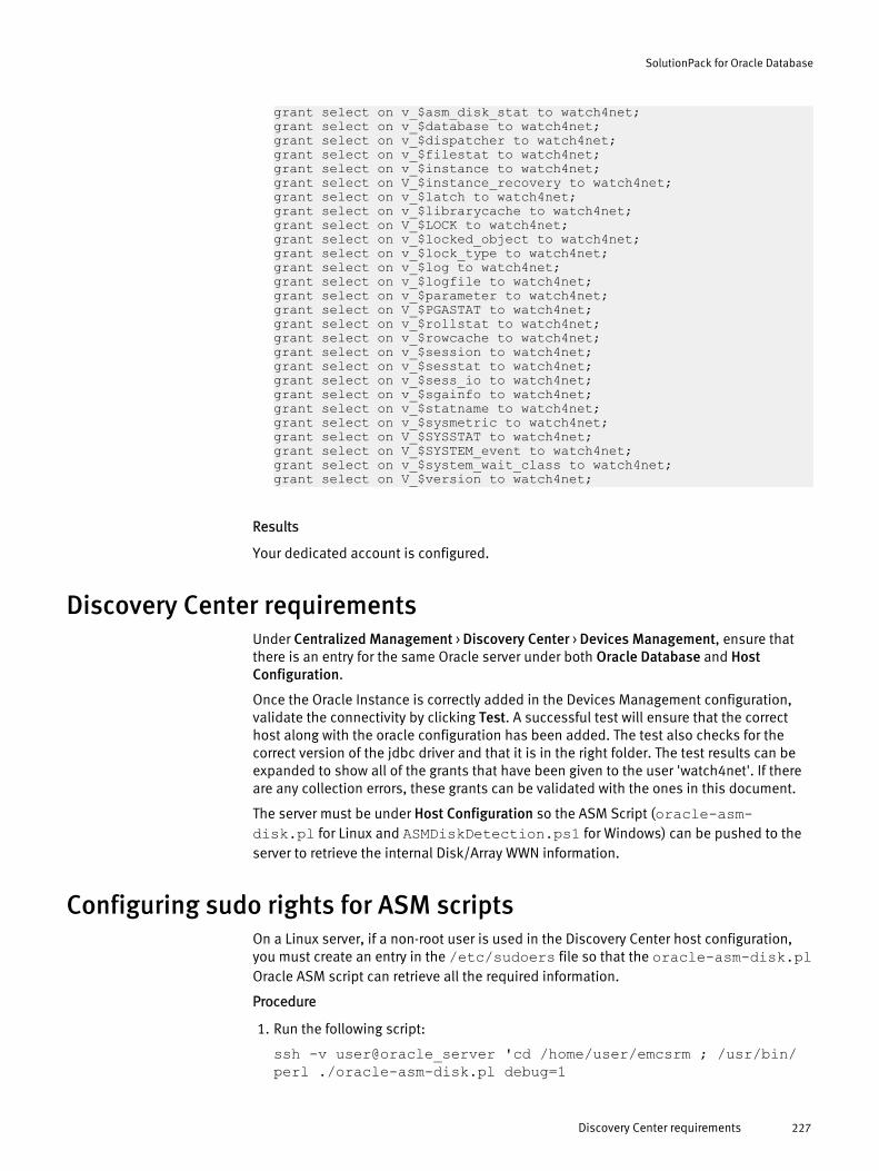
grant select on v_$asm_disk_stat to watch4net;grant select on v_$database to watch4net;grant select on v_$dispatcher to watch4net;grant select on v_$filestat to watch4net;grant select on v_$instance to watch4net;grant select on V_$instance_recovery to watch4net;grant select on v_$latch to watch4net;grant select on v_$librarycache to watch4net;grant select on V_$LOCK to watch4net;grant select on v_$locked_object to watch4net;grant select on v_$lock_type to watch4net;grant select on v_$log to watch4net;grant select on v_$logfile to watch4net;grant select on v_$parameter to watch4net;grant select on V_$PGASTAT to watch4net;grant select on v_$rollstat to watch4net;grant select on v_$rowcache to watch4net;grant select on v_$session to watch4net;grant select on v_$sesstat to watch4net;grant select on v_$sess_io to watch4net;grant select on v_$sgainfo to watch4net;grant select on v_$statname to watch4net;grant select on v_$sysmetric to watch4net;grant select on V_$SYSSTAT to watch4net;grant select on V_$SYSTEM_event to watch4net;grant select on v_$system_wait_class to watch4net;grant select on V_$version to watch4net;
Results
Your dedicated account is configured.
Discovery Center requirementsUnder Centralized Management > Discovery Center > Devices Management, ensure thatthere is an entry for the same Oracle server under both Oracle Database and HostConfiguration.
Once the Oracle Instance is correctly added in the Devices Management configuration,validate the connectivity by clicking Test. A successful test will ensure that the correcthost along with the oracle configuration has been added. The test also checks for thecorrect version of the jdbc driver and that it is in the right folder. The test results can beexpanded to show all of the grants that have been given to the user 'watch4net'. If thereare any collection errors, these grants can be validated with the ones in this document.
The server must be under Host Configuration so the ASM Script (oracle-asm-disk.pl for Linux and ASMDiskDetection.ps1 for Windows) can be pushed to theserver to retrieve the internal Disk/Array WWN information.
Configuring sudo rights for ASM scriptsOn a Linux server, if a non-root user is used in the Discovery Center host configuration,you must create an entry in the /etc/sudoers file so that the oracle-asm-disk.plOracle ASM script can retrieve all the required information.
Procedure
1. Run the following script:
ssh -v user@oracle_server 'cd /home/user/emcsrm ; /usr/bin/perl ./oracle-asm-disk.pl debug=1
SolutionPack for Oracle Database
Discovery Center requirements 227

The end of the script output contains the recommended settings for configuringthe /etc/sudoers file.
2. Optionally, you can edit the /etc/sudoers file directly with the following lines:
'Defaults:user !requiretty''Defaults:user env_keep += "ORACLE_SID"''user ALL=(root) NOPASSWD: /usr/local/bin/inq -wwn -dev *, /bin/raw -qa, /lib/udev/scsi_id --page\\=0x83 *''user ALL=(oracle) NOPASSWD: /u01/app/oracle/product/12.1.0/grid/bin/asmcmd lsdsk'
3. Replace /u01/app/oracle/product/12.1.0/grid/bin with yourORACLE_HOME to reflect your Oracle install.
Note
If your Linux server does not support the scsi_id command, install the inq application.On Windows, the ASM script will only work for a user with admin rights.
Limitationsl The All > Report Library > Oracle Database > Inventory > List all servers report does not
work.
l On a Windows server, the ASMDiskDetection.ps1 script must be run using anaccount that belongs to the 'Administrators' group. With non-admin discovery onWindows, reports such as ASM Datafile Distribution and ASM Disks (under DatabaseSummary) will not work.
SolutionPack for Oracle Database
228 EMC ViPR SRM 3.7 SolutionPack Installation and Configuration Guide
CHAPTER 34
SolutionPack for Oracle MySQL Database
l Overview............................................................................................................. 230l Preparing MySQL database for discovery and data collection ............................. 230l Installing the SolutionPack .................................................................................231
SolutionPack for Oracle MySQL Database 229
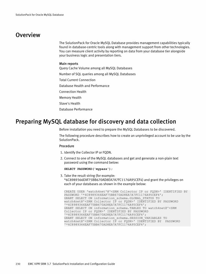
OverviewThe SolutionPack for Oracle MySQL Database provides management capabilities typicallyfound in database-centric tools along with management support from other technologies.You can measure client activity by reporting on data from your database tier alongsideyour business logic and presentation tiers.
Main reportsQuery Cache Volume among all MySQL Databases
Number of SQL queries among all MySQL Databases
Total Current Connection
Database Health and Performance
Connection Health
Memory Health
Slave's Health
Database Performance
Preparing MySQL database for discovery and data collectionBefore installation you need to prepare the MySQL Databases to be discovered.
The following procedure describes how to create an unprivileged account to be use by theSolutionPack.
Procedure
1. Identify the Collector IP or FQDN.
2. Connect to one of the MySQL databases and get and generate a non-plain textpassword using the command below:
SELECT PASSWORD('mypass');
3. Take the result string (for example:*6C8989366EAF75BB670AD8EA7A7FC1176A95CEF4) and grant the privileges oneach of your databases as shown in the example below:
CREATE USER 'watch4net'@'<SRM Collector IP or FQDN>' IDENTIFIED BY PASSWORD '*6C8989366EAF75BB670AD8EA7A7FC1176A95CEF4';GRANT SELECT ON information_schema.GLOBAL_STATUS TO watch4net@'<SRM Collector IP or FQDN>' IDENTIFIED BY PASSWORD '*6C8989366EAF75BB670AD8EA7A7FC1176A95CEF4';GRANT SELECT ON information_schema.TABLES TO watch4net@'<SRM Collector IP or FQDN>' IDENTIFIED BY PASSWORD '*6C8989366EAF75BB670AD8EA7A7FC1176A95CEF4';GRANT SELECT ON information_schema.SESSION_VARIABLES TO watch4net@'<SRM Collector IP or FQDN>' IDENTIFIED BY PASSWORD '*6C8989366EAF75BB670AD8EA7A7FC1176A95CEF4';
SolutionPack for Oracle MySQL Database
230 EMC ViPR SRM 3.7 SolutionPack Installation and Configuration Guide
Installing the SolutionPack
Before you begin
l Determine whether you need a SolutionPack license file by checking the featurenames and expiration dates listed in Centralized Management > LicenseManagement. If the license is not listed, obtain one by completing a Support Request(SR) form, which you can find on the EMC Online Support website at http://support.emc.com.
l Make sure the core modules, such as the Module-Manager, are up-to-date on allservers since not all module dependencies are validated during the SolutionPackinstallation. See the EMC M&R (Watch4net) Installation and Configuration Guideprovides for more information.
Procedure
1. Log in to Centralized Management.
2. Select SOLUTIONPACK CENTER.
3. Select the SolutionPack for MySQL Database in the Browse and Install SolutionPacksscreen.
4. Read the summary information and click Install.
5. Edit the default instance name, oracle-mysql-database, and click Next.
6. Set these values for the MySQL database server:
l Database hostname or IP address
l Database port
l Please select the credentials
7. If you have multiple instances of the Oracle MySQL database servers in yourconfiguration, click + to name each server and set the values shown in the previousstep.
8. Select Administration Web-Service Instance as the default and click Install.
9. When a checkmark appears next to the Collector and the Report, click OK.
10. Select Centralized Management > SolutionPack to verify the installed SolutionPack.
SolutionPack for Oracle MySQL Database
Installing the SolutionPack 231

SolutionPack for Oracle MySQL Database
232 EMC ViPR SRM 3.7 SolutionPack Installation and Configuration Guide

CHAPTER 35
SolutionPack for Physical Hosts
l Overview............................................................................................................. 234l Preparing your hosts for discovery and data collection........................................ 234l Installing the SolutionPack and configuring devices for discovery....................... 252l SolutionPack reconfiguration.............................................................................. 254l Recommendations.............................................................................................. 254l Limitations..........................................................................................................254
SolutionPack for Physical Hosts 233
OverviewThe SolutionPack for Physical Hosts enables you to monitor and generate real-time andhistorical reports on the performance of physical hosts.
The SolutionPack gives better insight into parameters such as capacity and utilizationassociated with an inventory of File Systems, Volume Groups, and Disks (local andremote).
Main reportsHost Information and details
File Systems, Volume Management summary report
Internal and SAN Disk Capacity Reports
Service level for LUNs mapped to host file systems
Performance metrics for host devices namely CPU, Memory, Disks
Native Multipathing and Powerpath reports
Supported collection interfacesFor information about supported collection interfaces, refer to the ViPR SRM SupportMatrix.
Preparing your hosts for discovery and data collectionYou need to configure your hosts to support resource discovery and data collection.
Refer to the following sections for additional details about configuring your hosts:
l Windows host configuration for discovery and data collection on page 235
l Unix host configuration for discovery and data collection on page 245
l Configuring ESX hosts to collect PowerPath metrics on page 251
Guidelines for hostnames and IP addressesYou have to follow these guidelines to ensure a successful host discovery and datacollection.
l The host names are in Domain Name Server (DNS) format with fully qualified domainname (FQDN).
l IP addresses are registered with the appropriate domain name servers and resolve fora reverse DNS lookup.
Guidelines for SNIA libraries and HBA driversIn order to discover SNIA-qualified HBA-related information for all the host platforms youshould ensure the right versions of SNIA library, drivers and firmware are in place.
l Ensure you have EMC-supported host bus adapter (HBA) drivers and firmware. EMCViPR SRM Support Matrix provides information for the supported SNIA compliantversion of the HBA driver.
l HBA Model and the compatible driver versions qualified by EMC can also be verifiedon https://support.emc.com > Product and Support Tools > Elab InteroperabilityNavigator. The vendor websites also list the EMC compatible drivers
SolutionPack for Physical Hosts
234 EMC ViPR SRM 3.7 SolutionPack Installation and Configuration Guide
l The vendor-specific SNIA libraries must be installed on the target host.
l The HBA model number and part number should be verified before updating thehosts with SNIA libraries for HBA.
l You can install the SNIA library as part of HBA driver installation package or install thelatest version of HBAnywhere (for Emulex installations) or SAN Surfer (for Qlogicinstallation).To discover an HP-UX host with a multi-port Fibre Channel card, the packageCommonIO bundle 0812(Dec 2008) or later should be present on the host to obtainthe updated FC-SNIA file set. INQ is dependent on binaries from CommonIO bundle.
Windows host configuration for discovery and data collection
Software to preinstall on hosts
l Install Powershell 2.0 or later on Windows hosts. Powershell can be downloaded from http://support.microsoft.com/kb/968929/en-us. User should have permissions toexecute powershell scripts. To provide permissions to execute scripts, type onpowershell terminal: Set-ExecutionPolicy RemoteSigned
Preinstall the following software on hosts using Windows 2003:
l Fcinfo is required to fetch HBA information. fcinfo.exe can be downloaded fromhttp://www.microsoft.com/download/en/details.aspx?displaylang=en&id=17530. Use the latest version of fcinfo and the defaultinstall location recommended by Windows.
l INQ 8.1.0.4 is supported only on 64-bit OS platforms. INQ 7.6.2 needs to be manuallycopied onto 32-bit target hosts. Platform specific INQ can be downloaded from:ftp://ftp.emc.com/pub/symm3000/inquiry/ The downloaded platformspecific binary should be renamed to inq and placed in any one of the belowspecified locations:
n C:\inq.exen C:\temp\inq.exen C:\windows\Temp\nl_dwd\inq.exeINQ binary should have executable permissions on the host.
User permissions required to be configured in ViPR SRMThe user credentials required for successful host discovery would be as follows:
l Local administrator
l Domain user who is part of administrator's group
l Non-admin user
A non-admin user is identified by ViPR SRM as a service account user or domain user whois neither a part of the Administrator group or domain Administrators group.Types of discovery allowed by different privilege levels on page 236
Configurations to be performed on the hostHosts should be pre-configured with certain WSMAN settings. These settings are requiredto prepare Windows hosts for ViPR SRM discovery of objects using WinRM services.
Configure one of the following listeners:
l WinRM HTTP listener with the following configuration:
n Negotiate authentication mode set to true.
SolutionPack for Physical Hosts
Windows host configuration for discovery and data collection 235
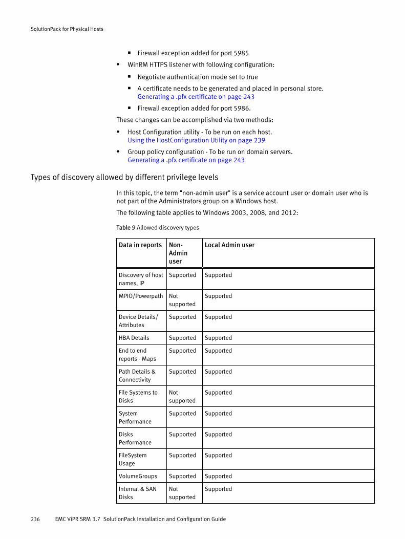
n Firewall exception added for port 5985
l WinRM HTTPS listener with following configuration:
n Negotiate authentication mode set to true
n A certificate needs to be generated and placed in personal store.Generating a .pfx certificate on page 243
n Firewall exception added for port 5986.
These changes can be accomplished via two methods:
l Host Configuration utility - To be run on each host.Using the HostConfiguration Utility on page 239
l Group policy configuration - To be run on domain servers.Generating a .pfx certificate on page 243
Types of discovery allowed by different privilege levels
In this topic, the term "non-admin user" is a service account user or domain user who isnot part of the Administrators group on a Windows host.
The following table applies to Windows 2003, 2008, and 2012:
Table 9 Allowed discovery types
Data in reports Non-Adminuser
Local Admin user
Discovery of hostnames, IP
Supported Supported
MPIO/Powerpath Notsupported
Supported
Device Details/Attributes
Supported Supported
HBA Details Supported Supported
End to endreports - Maps
Supported Supported
Path Details &Connectivity
Supported Supported
File Systems toDisks
Notsupported
Supported
SystemPerformance
Supported Supported
DisksPerformance
Supported Supported
FileSystemUsage
Supported Supported
VolumeGroups Supported Supported
Internal & SANDisks
Notsupported
Supported
SolutionPack for Physical Hosts
236 EMC ViPR SRM 3.7 SolutionPack Installation and Configuration Guide
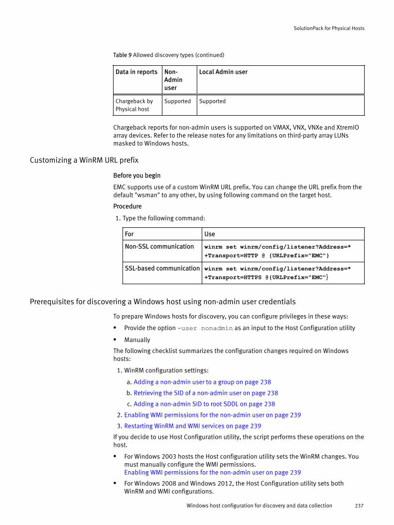
Table 9 Allowed discovery types (continued)
Data in reports Non-Adminuser
Local Admin user
Chargeback byPhysical host
Supported Supported
Chargeback reports for non-admin users is supported on VMAX, VNX, VNXe and XtremIOarray devices. Refer to the release notes for any limitations on third-party array LUNsmasked to Windows hosts.
Customizing a WinRM URL prefix
Before you begin
EMC supports use of a custom WinRM URL prefix. You can change the URL prefix from thedefault "wsman" to any other, by using following command on the target host.
Procedure
1. Type the following command:
For Use
Non-SSL communication winrm set winrm/config/listener?Address=*+Transport=HTTP @ {URLPrefix="EMC"}
SSL-based communication winrm set winrm/config/listener?Address=*+Transport=HTTPS @{URLPrefix="EMC"}
Prerequisites for discovering a Windows host using non-admin user credentials
To prepare Windows hosts for discovery, you can configure privileges in these ways:
l Provide the option -user nonadmin as an input to the Host Configuration utility
l Manually
The following checklist summarizes the configuration changes required on Windowshosts:
1. WinRM configuration settings:
a. Adding a non-admin user to a group on page 238
b. Retrieving the SID of a non-admin user on page 238
c. Adding a non-admin SID to root SDDL on page 238
2. Enabling WMI permissions for the non-admin user on page 239
3. Restarting WinRM and WMI services on page 239
If you decide to use Host Configuration utility, the script performs these operations on thehost.
l For Windows 2003 hosts the Host configuration utility sets the WinRM changes. Youmust manually configure the WMI permissions.Enabling WMI permissions for the non-admin user on page 239
l For Windows 2008 and Windows 2012, the Host Configuration utility sets bothWinRM and WMI configurations.
SolutionPack for Physical Hosts
Windows host configuration for discovery and data collection 237

These procedures are only available in ViPR SRM 3.5.1.
Adding a non-admin user to a group
Before you begin
l On a Windows 2003 host, the non-admin user should be part of the following groups:
n TelnetClients
n Performance Monitor Users
n Performance Log Users
n Distributed COM Users
On a Windows 2008/2012 host a non-admin user should be part of the following groups:
l Performance Monitor Users
l Performance Log Users
l Add non-admin users to the group WinRMRemoteWMIUsers__ . If that group does notexist, add the user to Distributed COM Users group.
Procedure
1. Go to Start.
2. Right-click Computer name and click Manage.
3. On the Computer management window, click Local Users and Groups.
4. Right-click the non-admin user and select Properties.
5. Select the MemberOf tab.
6. Click the Add button and key in the group name.
7. Click Ok, then click Apply.
8. Repeat these steps to add Performance Monitor Users, Performance Log Users andTelnetClients.
9. click Ok
Retrieving the SID of a non-admin user
Procedure
1. Run the command wmic useraccount get name,sid at a command prompt.
2. From the output of the command, capture the SID of the non-admin user.
Adding a non-admin SID to root SDDL
Procedure
1. Open a command prompt.
2. Type the following command to add the SID.
winrm set winrm/config/service @{RootSDDL="O:NSG:BAD:P(A;;GA;;;BA)(A;;GA;;;<non-admin-sid>)S:P(AU;FA;GA;;;WD)(AU;SA;GWGX;;;WD)"}
Replace <non-admin-sid> in this command with the SID you obtained.
SolutionPack for Physical Hosts
238 EMC ViPR SRM 3.7 SolutionPack Installation and Configuration Guide

Enabling WMI permissions for the non-admin user
Procedure
1. Go to Start.
2. Right click Computer name and click Manage.
3. On the Computer management window, expand Services and Applications.
4. Select WMI Control.
5. Right click WMI Control and select properties.
6. Click Security.
7. Select Root and click the Security button.
8. Add the non-admin user (hostname\non-admin-username) and click ok.
9. Select the check boxes for Enable Account, Read Security, and Remote Enable.
10. Click Advanced > edit on non-admin user > Apply onto > This namespace andsubnamespaces.
11. Click Ok, click Apply, and click Ok.
Restarting WinRM and WMI services
Procedure
1. Go to Start > Run.
2. Type the command services.msc.
3. Right click Windows Remote Management and click start.
In case the services are already running, click restart.
Using the HostConfiguration Utility
The host configuration utility is packaged along with SolutionPack for Physical Hosts. It isavailable at <APG Home Directory/Collecting/Stream Collector/Generic-RSC/scripts/windows>The script verifies and performs the following actions:
l Ensures that the WINRM service is running
l Creates a listener port for accepting WS-MAN requests
l Adds firewall exceptions to open port 5985 as non-SSL and 5986 as SSL
l Sets Basic or Negotiate authentication mode, based on input argument to script (-authType <Authentication_type>), to true.
l Sets MaxTimeout value to 300000 ms.
l Checks whether fcinfo package is present on the host, if Windows 2003
l Verifies the presence of INQ on the host and checks its version, if Windows 2003
Usage./hostconfig-srm.ps1 <-verify | -set | -set -force> [-authType<authentication_type>] [-ssl [-thumbprint <thumbprint_value>][-CN <certificate_hostname>]] [-user <username>][-help]
SolutionPack for Physical Hosts
Windows host configuration for discovery and data collection 239
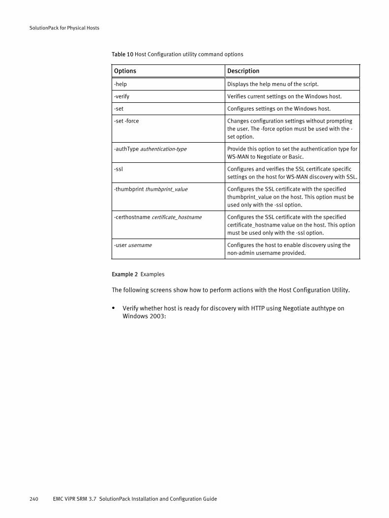
Table 10 Host Configuration utility command options
Options Description
-help Displays the help menu of the script.
-verify Verifies current settings on the Windows host.
-set Configures settings on the Windows host.
-set -force Changes configuration settings without promptingthe user. The -force option must be used with the -set option.
-authType authentication-type Provide this option to set the authentication type forWS-MAN to Negotiate or Basic.
-ssl Configures and verifies the SSL certificate specificsettings on the host for WS-MAN discovery with SSL.
-thumbprint thumbprint_value Configures the SSL certificate with the specifiedthumbprint_value on the host. This option must beused only with the -ssl option.
-certhostname certificate_hostname Configures the SSL certificate with the specifiedcertificate_hostname value on the host. This optionmust be used only with the -ssl option.
-user username Configures the host to enable discovery using thenon-admin username provided.
Example 2 Examples
The following screens show how to perform actions with the Host Configuration Utility.
l Verify whether host is ready for discovery with HTTP using Negotiate authtype onWindows 2003:
SolutionPack for Physical Hosts
240 EMC ViPR SRM 3.7 SolutionPack Installation and Configuration Guide

Example 2 Examples (continued)
Figure 2 Verify that the host is ready for discovery with HTTP
l Set Negotiate authtype for a successful discovery with HTTP on Windows 2008:Figure 3 Set Negotiate authtype
Configuring group policyUse a group policy if you do not want to set the configuration on each and every host(either manually or using a script). The group policy lets you apply a set of configurationsacross a set of hosts. You have to configure the group policy so that it can be appliedacross hosts as required.
Procedure
1. Right-click Computer and select Manage.
2. Go to Features > Group Policy Management > Forest Domain name > Domains > DomainName > Default Domain Policy.
3. Right-click Default Domain Policy and select Edit.
The group policy editor appears.
4. Select Default Domain Policy > Computer Configuration > Policies > AdministrativeTemplates > Windows Components > Windows Remote Management.
SolutionPack for Physical Hosts
Windows host configuration for discovery and data collection 241

5. Modify the following parameters as required:
l Enable Allow automatic configuration of listeners.
l Enable Allow Negotiate Authentication (for domain user).
l Add Windows Firewall exception for Port 5985 - HTTP
l Add Windows Firewall exception for Port 5986 - HTTPS
Note
HTTPS listener configuration is not possible from Group Policy.
Configuring firewall port exception using group policyUsing group policy, you have to configure firewall port exception if you are not usingdefault ports.
Procedure
1. Click Computer.
2. Go to Computer Configurations > Policies > Windows Settings > Windows Firewall withAdvanced Security > Inbound Rules
3. Create a new inbound rule
This enables the WinRM communication.
Updating group policyIf you update the group policy on a domain controller, the changes are reflected on thecomputers that are part of the domain in approximately 90-120 minutes. Use thisprocedure to force update the group policy on the member computers.
Procedure
1. You can use any of the options for force update of group policy:
Option Comment
Run the command gpupdate/force on allthe member computers.
This command results in a fetch operation forthe group policy
This command has to be run on allthe hosts and hence maybecumbersome.
Change the Group Policy Refresh Interval inthe Group Policy Management editor underComputer Configuration > AdministrativeTemplates > System > Group Policy
Minimum possible time is 7minutes.
Reducing refresh interval is notrecommended as it increases theload on the network.
Generating a certificateWinRM HTTPS requires a local computer server authentication certificate or self-signedcertificate with a CN name installed on the host. The certificates should not have expiredor been revoked.
Perform the following to create certificates:
SolutionPack for Physical Hosts
242 EMC ViPR SRM 3.7 SolutionPack Installation and Configuration Guide

Procedure
1. Generate a .pfx certificate on page 243
2. Exporting the .pfx certificate on page 243
3. Importing the .pfx certificate on page 244
4. Generate a .cer file on page 244
5. Import the .cer file on page 244
Generating a .pfx certificate
You can generate the required certificate using any certificate generator. This proceduredemonstrates generating a certificate using makecert.
Procedure
1. From the command prompt, run C:\>makecert.exe -ss MY -srLocalMachine -n "CN=<certificatename>" -sky exchange -pe -a sha1 -eku 1.3.6.1.5.5.7.3.1This creates a certificate under the personal store. Use the following steps to verify thecertificate created using makecert.
2. On a Windows host, click Start > Run.
3. Type mmc and click OK.
The Console window appears.
4. Click File > Add/Remove Snap-in.
5. Select Certificates under Available snap-ins and click Add.
6. Select Computer account.
7. Click Finish.
8. Click OK in the Add or Remove snap ins window.
9. On the left pane, double click Certificates (Local Computer) > Personal > Certificates.
10. On the right pane double click the certificate listed.
11. Navigate to Details tab. Select Subject to get the CN Name and Thumbprint to get theThumbprint of the certificate.
Note the CN Name and Thumbprint value, which will be used later while creating aWSMAN listener for HTTPS.
Exporting the .pfx certificate
To use the same certificate on multiple hosts, the generated certificate has to beimported on other hosts.
Procedure
1. On a Windows host, click Start > Run.
2. Type mmc and click OK.
3. In the Console window, click Certificates (local Computer) > Personal > Certificates.
4. Double-click Certificates.
5. Under Details, click Copy to File.
6. In the Certificate Export Wizard select Yes, export the private key. and click Next.
SolutionPack for Physical Hosts
Windows host configuration for discovery and data collection 243

7. Select Include all certificates in the certification path if possible and click Next.
8. Type a password for the private key.
This password is used when you import this certificate on other hosts.
9. Type a filename and save the .pfx file.
Importing the .pfx certificate
You have to import the .pfx on other hosts if you want to use the same certificate onmultiple hosts.
Before you begin
The .pfx certificate must be copied on the host where it is to be imported.
Procedure
1. On a Windows host, click Start > Run.
2. Type mmc and click OK.
3. In the Console window, click Certificates (Local Computer) > Personal > Certificates
4. Right-click and select All Tasks > Import.
5. In the browse window, select the .pfx certificate and click OK.
Generating a .cer file
The .cer file is created from a .pfx certificate with only a public key, which is used alongwith the private key for a successful handshake between the client and server.
Procedure
1. Go to Start > Run > mmc > Certificates (Local Computer) > Personal > Certificates
2. Double-click Certificates.
3. Under Details, click Copy to File.
4. Select No, do not export the private keys.
5. Selecting the Encoding type as DER or Base-64, and click Next.
6. Type a file name and click Save.
Importing a .cer file
You have to import the .cer file on the collector host to enable a successful handshakebetween the server and the client.
Procedure
1. Copy the .cer file on the collector host.
2. Log in to the collector.
3. Run the command /opt/APG/Java/Sun-JRE/6.0u45/bin/keytool -import -file <Public_Certificate_File> -keystore /opt/APG/Java/Sun-JRE/6.0u45/lib/security/cacerts -alias <Name>
The command prompts for keystore’s password. The default password is changeit.
A sample output returned by the command:
Owner: CN=<CN Name>Issuer: CN=Root AgencySerial number: 522200243f029a894c741bcb83d58a5d
SolutionPack for Physical Hosts
244 EMC ViPR SRM 3.7 SolutionPack Installation and Configuration Guide
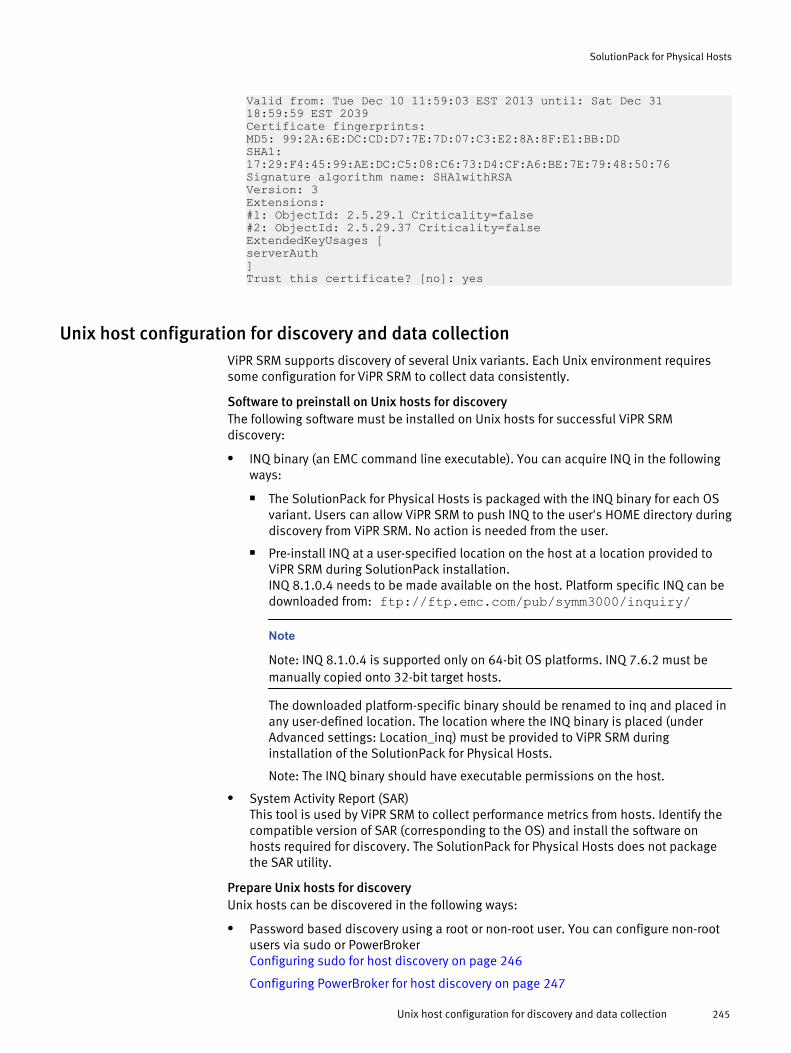
Valid from: Tue Dec 10 11:59:03 EST 2013 until: Sat Dec 3118:59:59 EST 2039Certificate fingerprints:MD5: 99:2A:6E:DC:CD:D7:7E:7D:07:C3:E2:8A:8F:E1:BB:DDSHA1:17:29:F4:45:99:AE:DC:C5:08:C6:73:D4:CF:A6:BE:7E:79:48:50:76Signature algorithm name: SHA1withRSAVersion: 3Extensions:#1: ObjectId: 2.5.29.1 Criticality=false#2: ObjectId: 2.5.29.37 Criticality=falseExtendedKeyUsages [serverAuth]Trust this certificate? [no]: yes
Unix host configuration for discovery and data collectionViPR SRM supports discovery of several Unix variants. Each Unix environment requiressome configuration for ViPR SRM to collect data consistently.
Software to preinstall on Unix hosts for discoveryThe following software must be installed on Unix hosts for successful ViPR SRMdiscovery:
l INQ binary (an EMC command line executable). You can acquire INQ in the followingways:
n The SolutionPack for Physical Hosts is packaged with the INQ binary for each OSvariant. Users can allow ViPR SRM to push INQ to the user's HOME directory duringdiscovery from ViPR SRM. No action is needed from the user.
n Pre-install INQ at a user-specified location on the host at a location provided toViPR SRM during SolutionPack installation.INQ 8.1.0.4 needs to be made available on the host. Platform specific INQ can bedownloaded from: ftp://ftp.emc.com/pub/symm3000/inquiry/
Note
Note: INQ 8.1.0.4 is supported only on 64-bit OS platforms. INQ 7.6.2 must bemanually copied onto 32-bit target hosts.
The downloaded platform-specific binary should be renamed to inq and placed inany user-defined location. The location where the INQ binary is placed (underAdvanced settings: Location_inq) must be provided to ViPR SRM duringinstallation of the SolutionPack for Physical Hosts.
Note: The INQ binary should have executable permissions on the host.
l System Activity Report (SAR)This tool is used by ViPR SRM to collect performance metrics from hosts. Identify thecompatible version of SAR (corresponding to the OS) and install the software onhosts required for discovery. The SolutionPack for Physical Hosts does not packagethe SAR utility.
Prepare Unix hosts for discoveryUnix hosts can be discovered in the following ways:
l Password based discovery using a root or non-root user. You can configure non-rootusers via sudo or PowerBrokerConfiguring sudo for host discovery on page 246
Configuring PowerBroker for host discovery on page 247
SolutionPack for Physical Hosts
Unix host configuration for discovery and data collection 245
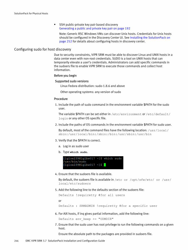
l SSH public-private key pair based discoveryGenerating a public and private key pair on page 192
Note: Generic RSC Windows VMs can discover Unix hosts. Credentials for Unix hostsshould be configured in the Discovery Center UI. See Installing the SolutionPack onpage 252 for details about configuring hosts in discovery center.
Configuring sudo for host discoveryDue to security constraints, ViPR SRM must be able to discover Linux and UNIX hosts in adata center even with non-root credentials. SUDO is a tool on UNIX hosts that cantemporarily elevate a user’s credentials. Administrators can add specific commands inthe sudoers file to enable ViPR SRM to execute those commands and collect hostinformation.
Before you begin
Supported sudo versions
Linux Fedora distribution: sudo-1.8.6 and above
Other operating systems: any version of sudo
Procedure
1. Include the path of sudo command in the environment variable $PATH for the sudouser.
The variable $PATH can be set either in /etc/environment or /etc/default/login or any other OS specific file.
2. Include the paths of OS commands in the environment variable $PATH for sudo user.
By default, most of the command files have the following location: /usr/local/sbin:/usr/local/bin:/sbin:/bin:/usr/sbin:/usr/bin
3. Verify that the $PATH is correct.
a. Log in as sudo user
b. Type which sudo.
4. Ensure that the sudoers file is available.
By default, the sudoers file is available in /etc or /opt/sfw/etc/ or /usr/local/etc/sudoers
5. Add the following line to the defaults section of the sudoers file:
Defaults !requiretty #for all usersor
Defaults : SRMADMIN !requiretty #for a specific user
6. For AIX hosts, if inq gives partial information, add the following line:
Defaults env_keep += "ODMDIR"7. Ensure that the sudo user has root privilege to run the following commands on a given
host.
Ensure the absolute path to the packages are provided in sudoers file.
SolutionPack for Physical Hosts
246 EMC ViPR SRM 3.7 SolutionPack Installation and Configuration Guide
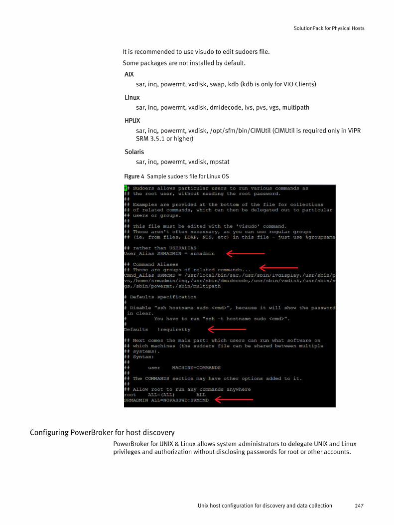
It is recommended to use visudo to edit sudoers file.
Some packages are not installed by default.
AIX
sar, inq, powermt, vxdisk, swap, kdb (kdb is only for VIO Clients)
Linux
sar, inq, powermt, vxdisk, dmidecode, lvs, pvs, vgs, multipath
HPUX
sar, inq, powermt, vxdisk, /opt/sfm/bin/CIMUtil (CIMUtil is required only in ViPRSRM 3.5.1 or higher)
Solaris
sar, inq, powermt, vxdisk, mpstat
Figure 4 Sample sudoers file for Linux OS
Configuring PowerBroker for host discoveryPowerBroker for UNIX & Linux allows system administrators to delegate UNIX and Linuxprivileges and authorization without disclosing passwords for root or other accounts.
SolutionPack for Physical Hosts
Unix host configuration for discovery and data collection 247
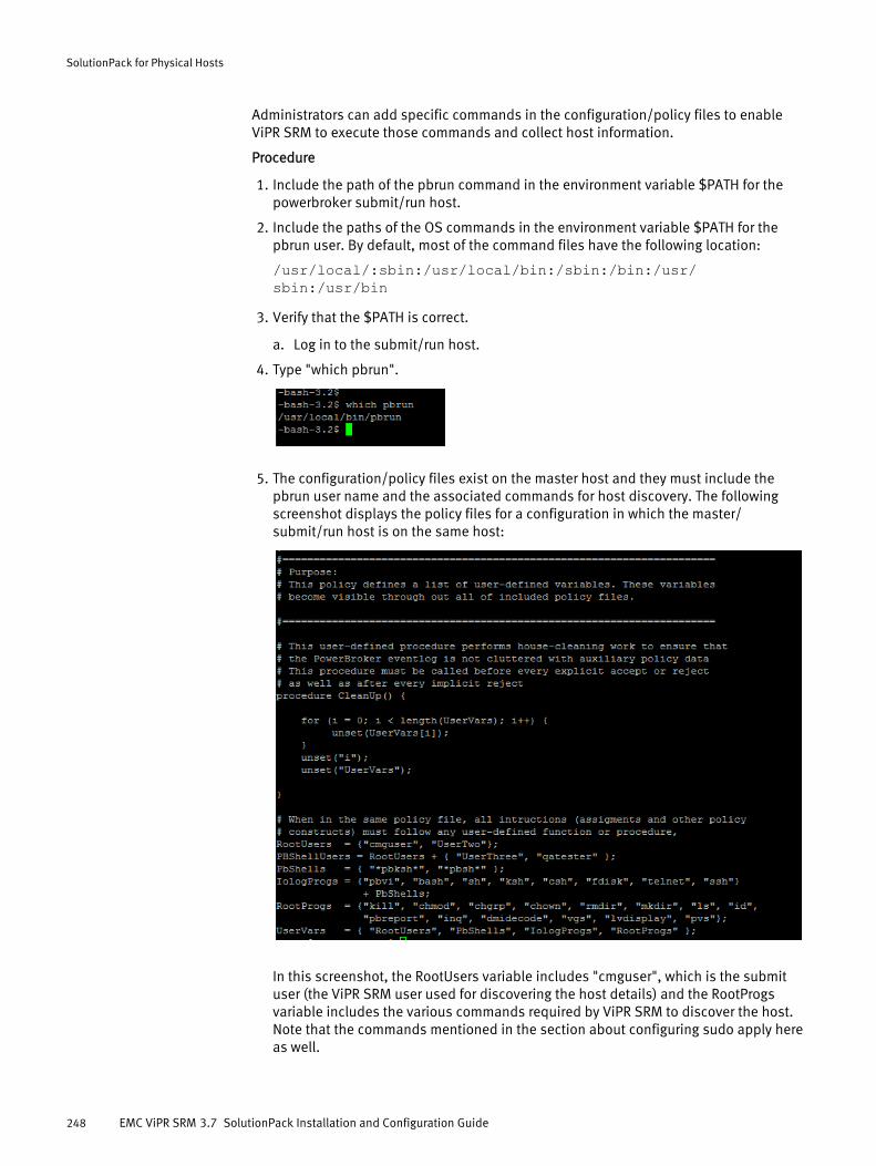
Administrators can add specific commands in the configuration/policy files to enableViPR SRM to execute those commands and collect host information.
Procedure
1. Include the path of the pbrun command in the environment variable $PATH for thepowerbroker submit/run host.
2. Include the paths of the OS commands in the environment variable $PATH for thepbrun user. By default, most of the command files have the following location:
/usr/local/:sbin:/usr/local/bin:/sbin:/bin:/usr/sbin:/usr/bin
3. Verify that the $PATH is correct.
a. Log in to the submit/run host.
4. Type "which pbrun".
5. The configuration/policy files exist on the master host and they must include thepbrun user name and the associated commands for host discovery. The followingscreenshot displays the policy files for a configuration in which the master/submit/run host is on the same host:
In this screenshot, the RootUsers variable includes "cmguser", which is the submituser (the ViPR SRM user used for discovering the host details) and the RootProgsvariable includes the various commands required by ViPR SRM to discover the host.Note that the commands mentioned in the section about configuring sudo apply hereas well.
SolutionPack for Physical Hosts
248 EMC ViPR SRM 3.7 SolutionPack Installation and Configuration Guide

Generating a public and private key pairFor the SSH key method of discovering UNIX hosts, you must generate a valid public andprivate key pair. You can choose any key generation tool to generate a valid public andprivate key pair.
Before you begin
Before you begin host discovery, you must have a public key present on all the UNIXhosts that are to be discovered using the private key. You can create SSH keys in any Unixenvironment and import them onto the ViPR SRM collector. EMC recommends that youcreate public-private SSH keys on ViPR SRM collectors (Linux VMs) where host discoverywill be initiated.
These steps describe the procedure to generate a public and private key pair for UNIXhosts using the ssh-keygen tool.
Note
The public key is to be added to the authorized_keys file on the target hosts intended fordiscovery and the private key is to be imported to the collector VMs where discovery istriggered.
Procedure
1. A Public-Private key can be generated using the following command:
ssh-keygen -t rsa -f <location_of_the_private_key/name_of_private_key_file> -N ""For example: ssh-keygen -t rsa -f /root/.ssh/id_rsa -N ””
2. Ensure that the public and private key pair that is generated has the followingpermissions:
l chmod 600 /root/.ssh/id_rsal chmod 644 /root/.ssh/id_rsa.pub
The private key file is id_rsa.
The public key file is id_rsa.pub.
3. To make the key pair functional, append the public key to <user's homedirectory>/.ssh/authorized_keys in the target UNIX host using the commandcat <location_of_the_public_key/name_of_public_key_file> >> /<user's homedirectory>/.ssh/authorized_keysFor example: cat /root/.ssh/id_rsa.pub >> /<user's homedirectory>/.ssh/authorized_keys
Next, import the private key to the Collector used for discovery.
Importing a private key into the Collector
Procedure
1. The private key should be placed inside APG's HOME directory (where APG isinstalled).
For example: Unix: /opt/APG/2. Type chown apg:apg <private_key_file>
SolutionPack for Physical Hosts
Unix host configuration for discovery and data collection 249

This command changes the owner.
The host is now ready for successful data collection.
Configuring SSH authenticationModify the /etc/ssh/sshd_config file on SLES 11 SP3 to allow successful sshauthentication.
Procedure
1. Change the following value to yes:
#PasswordAuthentication no <--- original#PasswordAuthentication yes <--- modified
Configuring ESX hosts to collect PowerPath metricsThis procedure describes how to configure ESX hosts to collect PowerPath metrics.
Before you begin
l Ensure that PowerPath/VE remote CLI (rpowermt) is installed on the host and enableperformance collection by running the rpowermt set perfmon={on[interval=<#seconds>] | off} host=HOST_FQDN command.The EMC ViPR SRM Support Matrix provides more information on supported PowerPathversions.
l Register ESX and enable performance for reporting.Refer to the Powerpath /Ve or RTOOLS documentation about how to register an ESXserver and enable performance.
l Configure the host where RTOOLS resides in generic-RSC based on the operatingsystem type (ESX-LINUX or ESX-Windows).
You can discover ESX and VMs running on the ESX server using the SolutionPack forVMware vCenter. However, the vCenter API does not provide all PowerPath metrics.Therefore, if you want PowerPath metrics, you need to provide the IP addresses of theRTOOLS host (physical host or VM) in addition to discovering the VMs using theSolutionPack for VMware vCenter. Depending on whether the RTOOL host is running onWindows or Linux OS, you have to configure the generic-rsc collector with OS type as ESXWindows or ESX Linux, respectively, to collect PowerPath metrics.
SolutionPack for Physical Hosts
250 EMC ViPR SRM 3.7 SolutionPack Installation and Configuration Guide
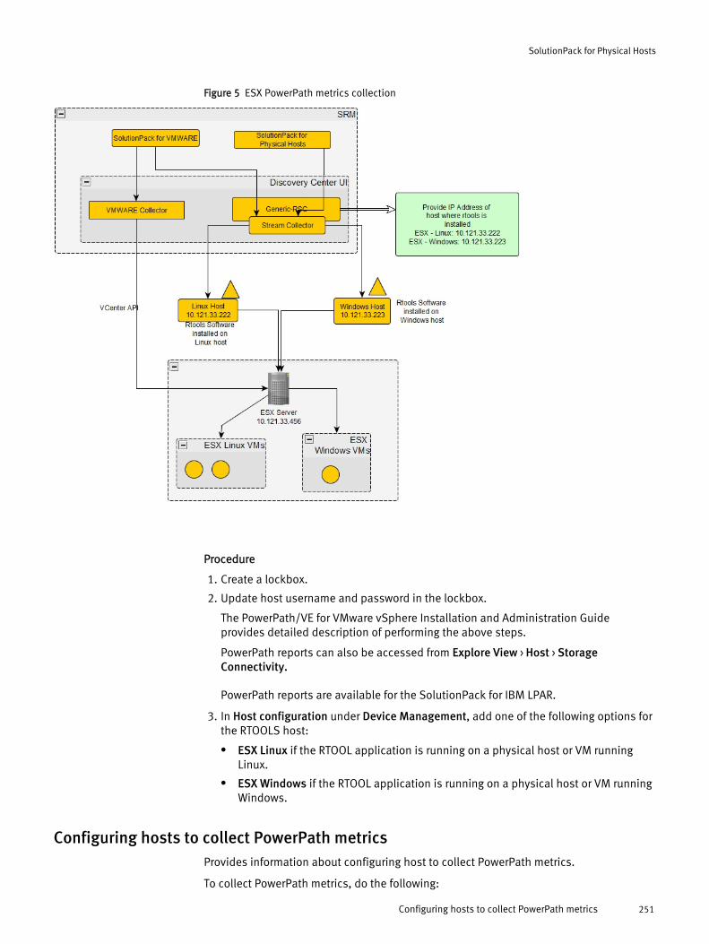
Figure 5 ESX PowerPath metrics collection
Procedure
1. Create a lockbox.
2. Update host username and password in the lockbox.
The PowerPath/VE for VMware vSphere Installation and Administration Guideprovides detailed description of performing the above steps.
PowerPath reports can also be accessed from Explore View > Host > StorageConnectivity.
PowerPath reports are available for the SolutionPack for IBM LPAR.
3. In Host configuration under Device Management, add one of the following options forthe RTOOLS host:
l ESX Linux if the RTOOL application is running on a physical host or VM runningLinux.
l ESX Windows if the RTOOL application is running on a physical host or VM runningWindows.
Configuring hosts to collect PowerPath metricsProvides information about configuring host to collect PowerPath metrics.
To collect PowerPath metrics, do the following:
SolutionPack for Physical Hosts
Configuring hosts to collect PowerPath metrics 251
Procedure
1. Install PowerPath CLI (powermt) on the host.
2. Enable performance collection by running the powermt set perfmon={on[interval=<#seconds>] | off} command.
Note
The EMC ViPR SRM Support Matrix provides more information on supported PowerPathversions.
Installing the SolutionPack and configuring devices for discovery
Before you begin
l Core modules must be up-to-date in all servers because not all module dependenciesare validated during the SolutionPack installation or update process.
l For non-admin users, the SolutionPack for Physical Hosts will report anauthentication error during discovery if the user is not part of the remote admin usersgroup. To avoid this issue, add non-admin users to the WinrMRemoteWMIUsers__group. If that group does not exist, add non-admin users to the DCOM group on theWindows host.
The steps below assume a typical four server deployment: Primary Backend, AdditionalBackend, Collector, and Front End.
Procedure
1. Click Administration .
2. Click Centralized Management.
3. Click SolutionPack Center.
4. Select the SolutionPack in the Browse and Install SolutionPacks window.
5. Click Install.
6. Type the instance name if you wish to change the default instance name of generic-host.
7. Assign a server for each component.
In a typical four server deployment, the recommended servers are selectedautomatically.
8. Click Next.
The window displays a note about Alert Consolidation.
9. If desired, select Enable the Host PowerPath Alerts.
10. Click Next.
The window displays reports settings.
11. In Administration Web-Service Instance, select an existing instance or create acustom instance.
12. Click Next.
The window displays script settings.
13. Select the performance metrics that you want to collect. Click Use advanced settingsto configure the absolute paths of the binaries.
SolutionPack for Physical Hosts
252 EMC ViPR SRM 3.7 SolutionPack Installation and Configuration Guide
14. Click Install.
15. Click Ok. Monitor the installation logs to ensure that the installation completessuccessfully.
16. Click Discovery Center > Devices Management.
17. Click Host configuration.
These steps describe how to add hosts individually. For information about usingdiscovery groups to use the same credentials to discover multiple hosts, see Addingdevices to discovery groups on page 274.
18. Click Add New Device.
19. Select the Server and Instance where you want to store the configuration details forthis device.
Server: If multiple collectors are deployed then choose the collector from the dropdown where "generic-host: script block" is installed.
Instance: Generic-RSC is the default instance name unless an additional "generic-rsc"block is installed.
20. Enter the hostname and OS type.
21. For AIX, ESX-Linux, HPUX, Linux, or Solaris hosts, from the Authentication Type drop-down menu, select:
l Password based if you are using password based authentication.
l Public key based if you are using key-based authentication.
22. For ESX-Windows or Windows hosts, from the Connection Type drop-down menu,select:
l HTTPS if you intend to use SSL certificates for authentication.
l HTTP if you intend not to use SSL certificates for authentication.
23. For Windows, if you have a custom WinRM URLPrefix, enter the same. Leave it blank ifwsman is the default URLPrefix.
24. Provide the username (root / non-root / administrator / non-admin / service accountuser).
25. If you are using password based authentication (Unix) or HTTP based Connection type(Windows), provide the password for the host.
26. If you are using key-based authentication, provide the absolute location of the privatekey:
/opt/APG/<Name of private key>27. Type the network port. (The default for SSH is 22.)
28. Click Test to validate the credentials.
29. Click OK.
30. Click Save.
31. Repeat steps 18 through 29 to add all of the hosts to be discovered.
SolutionPack for Physical Hosts
Installing the SolutionPack and configuring devices for discovery 253
Note
To manually import a template of Host devices from previous versions of SRM to 3.7,follow the steps below. (These steps are not required if an upgrade is done.)
a. Insert an empty column ‘winrmpath’ between columns ‘conntype’ and ‘authtype’ inthe Hostconfiguration.csv or Hostconfiguration.xls file.
b. Import the new file.
SolutionPack reconfiguration
If you want to change the answers that were provided during the SolutionPackinstallation, you can change them by reconfiguring the SolutionPack.
Procedure
1. Click Administration .
2. Under Centralized Management, click SolutionPacks > Other Components and selectthe generic-rsc instance.
The SolutionPack Reconfiguration dialog box appears.
3. Change the configuration as desired.
4. Click Reconfigure.
Recommendationsl Do not discover the same host using agentless discovery and agent-based discovery.
Simultaneous discovery results in duplicate data collection. If you switch fromagentless discovery to agent-based discovery (or vice versa), the metrics collectedfrom the previous discovery mechanism become inactive.
LimitationsLearn about the limitations that apply to the SolutionPack for Physical Hosts.
l After upgrading ViPR SRM from any version prior to 3.6 to 3.7, any host withuppercase "hostname" would be listed twice in Physical Host reports (bothuppercase and lowercase). With default vstatus configuration, these double entrieswould show up in report for 14 days, after which only lower case entries would beseen. The "inactive" metrics generated through UpperCase hostname would remain indatabase until they are cleaned up from the database.
l This SolutionPack does not identify LUNs from the Hitachi AMS200 array.
l Due to the unavailability of WWN using in-band SCSI mechanisms accessible to thehosts, the software cannot match the LUNs associated with an array to the disks fromthe hosts.
l On Windows hosts, if the multipathing software on the host does not support anyarray, the LUN from that array may show up as multiple host physical drives.
SolutionPack for Physical Hosts
254 EMC ViPR SRM 3.7 SolutionPack Installation and Configuration Guide

l Physical hosts connected to IBM DS 8000 do not show "Connected array" and "LUN"in the SAN disks report.
SolutionPack for Physical Hosts
Limitations 255

SolutionPack for Physical Hosts
256 EMC ViPR SRM 3.7 SolutionPack Installation and Configuration Guide

CHAPTER 36
SolutionPack for Storage Compliance
l Overview............................................................................................................. 258l Where to find the latest SolutionPack software....................................................258l Installing the SolutionPack..................................................................................258
SolutionPack for Storage Compliance 257
OverviewThe SolutionPack for Storage Compliance allows users to manage compliance policiesand rules and perform ESM matching. It also generates breach, track configurationchanges, and policy reports. This enables the identification of any deviation fromconfiguration best practices, including items that do not comply with the EMC ViPR SRMRelease Notes. The compliance reports can be found under Operations > StorageCompliance. The Policy & Rule Management and ESM management screen can belaunched by clicking on the Storage Compliance link in the Administration screen.
Main reportsBreach Report
Track Configuration Changes
View Policies
Supported collection interfacesFor information about supported collection interfaces, refer to the ViPR SRM SupportMatrix.
Where to find the latest SolutionPack softwareInstall the latest core software update for your product suite. SolutionPacks distributedwith core software have a 30-day free evaluation period. If you plan to use the softwarelonger than 30 days, you must install a SolutionPack license before the trial period ends.
This 30-day free evaluation only applies to new installations and is not available forupgraded installations. If you upgrade the core software and want to try a newSolutionPack, you must request a license for that SolutionPack by completing a SupportRequest (SR) form, which is available on the EMC Online Support website at http://support.emc.com.
Installing the SolutionPack
Before you begin
l EMC M&R will use SSH and a user account.
l ViPR SRM core modules must be up-to-date in all servers because not all moduledependencies are validated during the SolutionPack installation or update process.
l If you are installing on a Windows host, stop the process jucheck.exe. This is aJava JRE update validator and uses the same port as the SolutionPack.
l Do not install multiple instances of the Storage Compliance Backend because thesame port would be used for each installation. This will lead to service startup failure.
l Alerting backend service should be available during installation; otherwise alertingdefinition will not be created. The SolutionPack for Storage Compliance createsalerting definition for notifying mentioned users with email alerts for breaches/violations.
l Though the Compliance service comes up immediately, do not run ESM rules as theSolutionPack installation also populates the database with ESM data, for ESM rulevalidation, which takes some time to get the database populated (approximately 3-5minutes).
SolutionPack for Storage Compliance
258 EMC ViPR SRM 3.7 SolutionPack Installation and Configuration Guide

Procedure
1. Click Administration .
2. Click Centralized Management.
3. Click SolutionPack Center.
4. Select the SolutionPack in the Browse and Install SolutionPacks window.
5. Click Install.
6. Type the instance name.
7. Assign a server for each component.
In a typical four server deployment, the recommended servers are selectedautomatically.
8. Click Next.
The window displays compliance notification details.
9. Select an item in Breach Notification Details. If you select Add a new BreachNotification Details, select an instance to receive breach notifications.
10. Click Next.
11. From Frontend Web service, select the Frontend host details.
12. Select a Topology Service. To add a new gateway configuration, select Add a newTopology Service.
13. Select a configuration for Breach Notification Details.
Reuse the answers if another solution pack is using Alerting backend. Otherwisecreate a new configuration by selecting Add a new Breach Notification Details. In theAlerting Backend hostname or IP address, type the Primary Backend host. Type 2010as the port.
14. Select a configuration for Alert Consolidation Details.
Reuse the answers if another solution pack is using Alert Consolidation Details.Otherwise create a new configuration by selecting Add a new Alert ConsolidationDetails. In the Alert Consolidation hostname field, type the Primary Backend host.Type 2040 as the port.
If SOM RCA installation needs to be done, the alert consolidation configuration isrequired. For more details, refer to the "How to" article for SOM.
15. Click Next.
16. On the Compliance Rules page, click Next.
17. From Administration Web-Service Instance, select Default.
18. In Compliance Backend Host, for 4 VM installations, enter the Primary Backend host.
19. Click Next.
20. Click Install.
21. After Install of all the compliance components, click Ok.
After installation is complete, you need to restart the Tomcat for Compliance Frontendto point to the configured Backend. If the Web Service password is changed, then theCompliance Backend block needs to be reconfigured.
SolutionPack for Storage Compliance
Installing the SolutionPack 259

SolutionPack for Storage Compliance
260 EMC ViPR SRM 3.7 SolutionPack Installation and Configuration Guide

CHAPTER 37
SolutionPack for VI VirtualWisdom
l Overview............................................................................................................. 262l Preparing VI VirtualWisdom.................................................................................262l Installing the SolutionPack..................................................................................264
SolutionPack for VI VirtualWisdom 261
OverviewThe SolutionPack for VI VirtualWisdom accesses key performance and availabilitymetrics, including individual transactional performance from host to LUN, host to LUNoverview, link level aggregated metrics for throughput and errors, and a link levelinventory for impact assessment.
Main reports
Performance
Read and write exchange completion time, number of completed reads and writes
Health
Link errors (LOS, LOSync, BadEOF, CVErrors, LinkResets, CRCErrors) SCSI Errors(Aborts, BadStatusFrames)
Utilisation
Aggregate storage link utilisation, individual initiator to LUN utilisation
Optional metrics
Read and writes frame count, read and write payload sizes
Supported collection interfacesFor information about supported collection interfaces, refer to the ViPR SRM SupportMatrix.
Preparing VI VirtualWisdomIdentify the information required to support resource discovery and data collection beforeinstalling the SolutionPack for VI VirtualWisdom and perform any necessary pre-configuration.
ViPR SRMcollects VirtualWisdom data using proxy software installed on theVirtualWisdom Portal Server. Download and install the proxy software on theVirtualWisdom Portal Server
Procedure
1. Obtain the proxy installation package using Virtual Instruments customer credentialsfrom their SFDC portal, or from ftp.virtualinstruments.com. The package is located inthe CURRENT directory.
2. Copy the installation package to the VirtualWisdom server.
3. Unzip the package into a suitable temporary directory.
4. Stop the VirtualWisdom service.
5. Open a command prompt.
Note
You may need to run as Administrator to allow files to be copied.
6. Navigate to the temporary directory where the proxy is unzipped and run theinstall.bat script.
7. Enter the VirtualWisdom installation path.
8. Restart the VirtualWisdom service.
SolutionPack for VI VirtualWisdom
262 EMC ViPR SRM 3.7 SolutionPack Installation and Configuration Guide
Results
You do not need to perform any addtional configuration of the proxy which runs as part ofthe standard VirtualWisdom.
After you finish
Create a VirtualWisdom user account dedicated for access by the SolutionPack for VIVirtualWisdom. When you install the SolutionPack, you will provide these credentialswhich are then stored on the Collector host in:APG/Collecting/XML-Collector/vi-virtualwisdom/conf/VI-proxyRequest.xml.
Connecting to multiple VirtualWisdom Portal ServersIf you have more than one VirtualWisdom Portal Server, you can combine data frommultiple Portal Servers. The data will populate the same reports.
Before you begin
Install and configure the proxy software on each VirtualWisdom Portal Server.
Use this configuration to collect the same metrics from all Portal Servers using the samefrequency (poll cycle) and credentials. Each host will be polled in the sequence youspecify in the configuration file.
Procedure
1. On the Collector host, navigate to APG/Collecting/XML-Collector/vi-virtualwisdom and open the VI-collector.xml file.
2. Add one or more Portal Server hosts to the configuration file by typing the additionalhost IP addresses.
<input>http://(host):8080/Proxy</input>
<host>ip_address</host> <host>ip_address</host> <parameter name="connect-type"> <value>any</value> </parameter>
3. If the VirtualWisdom WebServices port numbers are different for each Portal Serverhost, you can remove the port number from the <input> line and append the uniqueport numbers to the host address. For example:
<input>http://(host)/Proxy</input>
<host>ip_address:port</host> <host>ip_address:port</host> <parameter name="connect-type"> <value>any</value> </parameter>
4. Restart the VirtualWisdom collector by restarting its Collector Manager. Use one of thefollowing methods:
l APG/bin/manage-modules service restart collector-manager<instance-name>
l Start/stop the collector manager from Centralised Management.
SolutionPack for VI VirtualWisdom
Connecting to multiple VirtualWisdom Portal Servers 263

Installing the SolutionPack
Before you begin
l EMC ViPR SRM core modules must be up-to-date in all servers because not all moduledependencies are validated during the SolutionPack installation or update process.
Procedure
1. Click Administration .
2. Click Centralized Management.
3. Click SolutionPack Center.
4. Select the SolutionPack in the Browse and Install SolutionPacks window.
5. Click Install.
6. Type the instance name.
7. Assign a server for each component.
In a typical four server deployment, the recommended servers are selectedautomatically.
8. Click Next.
The window displays data collection details.
9. From the Data collection drop-down menu, select existing settings that have beenspecified for other components, or select Add a new data collection.
If you select Add a new data collection, type information about the data collection. InHostname or IP address to send data to, use localhost on port 2020, which is theCollector host where the Load Balancer Connector is installed.
10. Leave Enable alerting on data collected checked.
11. From the Alerting on data collection drop-down menu, select existing settings thathave been specified for other components, or select Add a new alerting datacollection.
If you select Add a new alerting on data collection, type information about the alertingconfiguration. In Alerting Backend hostname or IP address, specify the PrimaryBackend host.
12. In theServer Name field, type the VirtualWisdom Portal Server host.
13. In theServer Port field, type the port for the webservices proxy. The default is 8080.The value is configured in the virtualwisdom.properties file in theVirtualWisdom installation directory on the VirtualWisdom Portal Server.
14. In theUsername and Password fields, type the credentials used for authenticationwith the proxy.
15. Click Enable advanced settings to configure polling and collection settings.
16. Click Next.
The window displays reports settings.
17. In Administration Web-Service Instance, select an existing instance or create acustom instance.
18. Click Install.
SolutionPack for VI VirtualWisdom
264 EMC ViPR SRM 3.7 SolutionPack Installation and Configuration Guide

19. Click Ok. Monitor the installation logs to ensure that the installation completessuccessfully.
SolutionPack for VI VirtualWisdom
Installing the SolutionPack 265

SolutionPack for VI VirtualWisdom
266 EMC ViPR SRM 3.7 SolutionPack Installation and Configuration Guide
CHAPTER 38
SolutionPack for VMware vCenter
l Overview............................................................................................................. 268l Configuring the SolutionPack to collect Powerpath data...................................... 268l Installing this SolutionPack.................................................................................268l Post-install requirements.................................................................................... 271l Limitations..........................................................................................................271
SolutionPack for VMware vCenter 267
OverviewThe SolutionPack for VMware vCenter generates real-time and historical reports that helpyou understand VMware performance for VMware Hosts, Virtual Machines, virtualnetworks and DataStores.
Main reportsvCenter datacenter overview
Detailed datastore information
Detailed Virtual Machines, both running and offline
Configuring the SolutionPack to collect Powerpath dataThis procedure is required to collect PowerPath data from ESX servers.
For monitoring PowerPath performance and path status, an RTools host is required.RTools is the remote CLI software for managing the PowerPath software on ESXi (or other)hosts. The Collector will use the Generic-RSC Collector to issue RTools command scriptsto the RTools host to collect PowerPath data directly from the ESXi servers.
Procedure
1. Add the host name and credential of every ESXi host to the RTools default lockbox.Commands will fail if the lockbox is not populated.
The first use of the command creates the lockbox if necessary.
2. The RTools host has to be discovered by the Generic-RSC Collector. Discover it throughthe SolutionPack for Physical Hosts using the ESX Linux or the ESX Windows hosttype. Choose the Linux or Windows type appropriate for the RTools host so that thecollector can issue the correct format scripts.
3. Create the default lockbox on RTools Host and add ESXi hostname credentials:
rpowermt setup add_host host= username= password=4. Turn on performance monitoring on ESXi host from Rtools (if needed):
rpowermt set perfmon=on interval= host=5. For PASSWORD based discovery Suse Linux hosts from 3.0 RSC, it requires edits to the
sshd_config file. Note this file is located under /etc/ssh directory on discovery hosts.You must enable "PasswordAuthentication" and restart sshd service on the host.
lglah196:~/.ssh # grep Password /etc/ssh/sshd_config#PasswordAuthentication no #PermitEmptyPasswords nolglah196:~ # /etc/init.d/sshd restart Shutting down SSHdaemon done Starting SSH daemon donelglah196:~ #
Installing this SolutionPack
Before you begin
l Core modules must be up-to-date in all servers because not all module dependenciesare validated during the SolutionPack installation or update process.
SolutionPack for VMware vCenter
268 EMC ViPR SRM 3.7 SolutionPack Installation and Configuration Guide

Procedure
1. Click Administration .
2. Click Centralized Management.
3. Click SolutionPack Center.
4. Select the SolutionPack in the Browse and Install SolutionPacks window.
5. Click Install.
6. Type the instance name.
7. Assign a server for each component.
In a typical four server deployment, the recommended servers are selectedautomatically.
8. Click Next.
The window displays a note about Alert Consolidation.
9. Click Next.
The window displays pre-configured alert details.
10. To receive alerts, select Enable the Host PowerPath Alerts.
11. In Recipient for email alerts, enter the email addresses in which to send the alerts.
12. Click Next.
The window displays data collection details.
13. From the Data collection drop-down menu, select existing settings that have beenspecified for other components, or select Add a new data collection.
If you select Add a new data collection, type information about the data collection. InHostname or IP address to send data to, use localhost on port 2020, which is theCollector host where the Load Balancer Connector is installed.
14. From the Frontend Web service drop-down menu, select existing settings that havebeen specified for other components, or select Add a new Frontend Web service.
If you select Add a new Frontend Web service, type information about the FrontendWeb service.
15. Leave Enable Topology Backend on data collected checked.
16. From the Topology Service drop-down menu, select existing settings that have beenspecified for other components, or select Add a new Topology Service.
If you select Add a new Topology service, provide information about the topologyservice and the web service. In Topology Service hostname or IP address, specify thePrimary Backend.
From the Web-Service Gateway drop-down menu, select existing settings that havebeen specified for other components, or select Add new gateway. If you select Addnew gateway, provide information about the web-service gateway where the topologyservice resides.
17. Optionally, select Do you want to configure advanced settings to configure the metriccollection level, polling intervals, collection thread settings, and the re-synch interval.
a. In Metric Collect Level, select the level of metrics you want the SolutionPack tocollect per VMware collector block. The Metric Collect Level is an internal settingthat tells the SolutionPack for VMware vCenter how much data to collect. Thissetting is not related to vCenter statistics levels.
SolutionPack for VMware vCenter
Installing this SolutionPack 269

Collect-Level 1 collects the minimum required metrics related to capacity,topology, memory, and CPU.
Collect-Level 2 collects all metrics supported by Collect-Level 1 and additionally allmetrics related to disks and memory.
Collect-Level 3 collects all supported metrics, which includes metrics collectedunder Collect-Level 1 and Collect-Level 2.
b. In Polling interval for VMware vCenter collection, select a polling interval.
c. In Polling interval for VM files only, select a polling interval.
d. In Number of collecting threads, enter the number of collection threads.
e. In Number of collecting threads for VM files, enter the number of collectionthreads.
f. In Re-Sync interval, select an interval.
18. Click Next.
19. From Event database, select a database.
If you select Add a new Event Database, add the Primary Backend host in theDatabase hostname or IP address field.
20. Click Next.
The window displays reports settings.
21. Click Next.
22. Select Collect performance metrics for PowerPath Bus to collect performance metricsfor all the logical Bus managed by PowerPath agent.
23. Select Collect performance metrics for PowerPath LUNs to collect performancemetrics for all the logical devices managed by PowerPath agent.
24. Select Collect PowerPath range-bound performance metrics to collect range-boundperformance metrics. Selecting this option increases metric count significantly. Besure to correctly size your application before enabling this option.
25. Select Do you want to configure advanced settings to set the absolute path locationof the sudo and pbrun binaries.
26. Click Install.
27. Click Ok. Monitor the installation logs to ensure that the installation completessuccessfully.
28. Click Discovery Center > Devices Management.
29. Click VMware vCenter (vmware-vcenter-collect <version>) for data collection and/orVMware vCenter (vmware-vcenter-events <version>) for vCenter events collection.
These steps describe how to add VMware vCenter hosts individually. For informationabout using discovery groups to use the same credentials to discover multipleVMware vCenter hosts, see Adding devices to discovery groups on page 274.
30. Click Add New Device.
31. From Server, select the server where the device will be dispatched.
32. From Instance, select the instance of the vmware-vcenter-collect where the device willbe dispatched.
33. In Hostname or IP address, type the vCenter service host. Enter the Username andPassword used to poll vCenter.
SolutionPack for VMware vCenter
270 EMC ViPR SRM 3.7 SolutionPack Installation and Configuration Guide

34. Click Ok.
35. Click Save.
Post-install requirementsPerform these operations after the installation is complete.
To enable PowerPath LUN or Path performance data collection on Linux, navigate tothe /opt/APG/Collecting/Stream-Collector/<Instance Name>/conf/scripts/ directory.
Procedure
1. In the LunMappingDetection.pl script, setwant_powerpath_lun_performance=1.
By default, this flag is set to zero.
2. To enable the PowerPath LUN or Path performance data collection on Windows:
a. Navigate to the C:\Program Files\APG\Collecting\Stream-Collector\<Instance Name>\conf\scripts\windows directory.
b. In the LunMappingDetection.ps1 script, setpowerPathPerformanceCollection=enabled.
By default, this flag is set to disabled.
3. To enable events reporting, open the Web-Application configuration file (APG.xml)and uncomment the vmware-vcenter section and the ResourceLink tag.
4. Restart the Tomcat service to make the changes effective.
LimitationsThe Host Attributes report is missing the IP Address for VMware vCenter.
SolutionPack for VMware vCenter
Post-install requirements 271

SolutionPack for VMware vCenter
272 EMC ViPR SRM 3.7 SolutionPack Installation and Configuration Guide

CHAPTER 39
Discovery Center
This chapter includes the following topics:
l Adding devices to discovery groups.................................................................... 274
Discovery Center 273

Adding devices to discovery groupsDiscovery groups simplify the process of working with a large number of devices and theircorresponding IP addresses/hostnames and discovery credentials. For example, if youhave set of four user/password credentials used among twenty devices, using adiscovery group allows you to enter each set of credentials and all of the IP addresses/hostnames, and the discovery group will match the correct credentials to each device.
Procedure
1. From Centralized Management, click Discovery Center > Discovery Center Backends.
2. Select the Backend server.
3. Click Register.
4. Select the collector you want to use for discovering your SolutionPack objects.
5. If you are collecting VMware vCenter events, select the primary backend you want touse for discovering the events.
6. Click Register.
7. Click Discovery Center > Devices Management.
8. Click <Device Name>.
9. Click the Discovery Groups tab.
10. Click Add new Discovery group.
11. Provide a name for the group and click Ok.
12. Click the newly created group.
13. Under Credentials, click Add new entry.
14. Type the username.
15. If required, select the authentication type.
16. If you are using password authentication, provide the password and click Ok.
17. If you are using key-based authentication, provide the absolute location of the privatekey and click Ok.
18. Repeat the previous five steps to add as many username/password (or key)combinations as you would like.
19. Under Hostname or IP address, click Add new entry.
20. Provide the Hostname/IP Address of the device. If required, provide the Network Port.Click Ok.
21. Repeat the previous two steps to add as many devices as you would like.
22. Click Save.
23. Click the Collected Devices tab.
24. Click Discover.
25. Select the Discovery group and Discovery Mode and click Ok.
The progress bar is displayed above the Collected Devices tab.
26. When the progress bar is gone, click theDiscovery Results tab.
27. Click the group name that you added.
28. Under the group name, you can see the status of all the devices that you added.
Discovery Center
274 EMC ViPR SRM 3.7 SolutionPack Installation and Configuration Guide

29. Click Import to Collected Devices.
30. Merge the devices if you want to retain older devices that were added previously.
31. Click Ok.
32. Select the action and click Continue.
33. Click Save.
All of the devices have been added to discovery
Review your devices and credentials to avoid lockout of devices due to multipleattempts of incorrect credentials. EMC recommends that you create groups in such away that devices have a minimal set of credentials to be tried against. EMCrecommends using common public-private key pairs for multiple devices.
Discovery Center
Adding devices to discovery groups 275

Discovery Center
276 EMC ViPR SRM 3.7 SolutionPack Installation and Configuration Guide

CHAPTER 40
Troubleshooting
l Confirming report creation...................................................................................278l What to do if data does not appear in any reports................................................278l What to do if data does not appear in some reports.............................................278l External storage capacity is counted more than once in capacity reports............. 279l Authorization fails for passwords having special characters................................ 279l Troubleshooting discovery issues, slow reports, and missing data ..................... 279l Viewing collector errors in the Collector-Manager log files................................... 280
Troubleshooting 277

Confirming report creationAfter you install a SolutionPack, you can view its reports.
To view the reports:
Procedure
1. Go to User Interface > Report Library.
2. Click the SolutionPack to view its reports.
Results
It may take up to an hour to display all relevant information in these reports.
What to do if data does not appear in any reportsProcedure
1. After the completion of at least three collection cycles, verify if data is populating intothe reports. If there is still no data in the reports, continue to the next step.
2. Run the scheduled task to import data into reports. If there is still no data in thereports, continue to the next step.
3. To view the log files for errors, go to Centralized Management and click LogicalOverview > Collecting > Collector-Manager::<instance name> > Log Files.
Running a scheduled task to import data into reportsAfter you push a new configuration into a collector, a scheduled task runs and populatesthe reports with new data. You can manually run the scheduled task to import the datamore quickly.
Before you begin
Allow at least three polling cycles to pass before manually running the scheduled task.
Procedure
1. Click Administration .
2. Click Centralized Management.
3. Expand Scheduled Tasks.
4. Click Database.
5. Select the import-properties-Default task.
6. Click Run Now.
7. Confirm success in running the task in the Last Result and Last Result Time columns.
What to do if data does not appear in some reportsProcedure
1. Run the scheduled task to import data into reports. If there is still no data in thereports, continue to step 2.
2. Search for the metric in the database.
Troubleshooting
278 EMC ViPR SRM 3.7 SolutionPack Installation and Configuration Guide
3. To view the log files for errors, go to Centralized Management and click LogicalOverview > Collecting > Collector-Manager::<instance name> > Log Files.
Searching for metrics in the databaseYou can verify that a metric is being collected and used for reporting when you searchand find the metric in the database.
Procedure
1. Click Administration .
2. Under Modules, click Management of Database Metrics.
3. On the Metric Selection page, create the filter, type the number of results, and selectthe properties to display for the metric.
For example, to list up to 100 results of the Capacity metric with the properties ofdevice and IP, type name=='Capacity' in the Filter field, 100 in the Maximum resultsfield, and select device and IP for the Properties to show.
4. Click Query.
A list of the metric results appears. If nothing displays, the metric is not beingcollected.
External storage capacity is counted more than once in capacityreports
Enterprise capacities for a storage array include any external array capacity or FederatedTier Storage (FTS) Capacity.
To avoid double counting of external storage capacity in the enterprise capacity reports,do not discover the external storage array.
Authorization fails for passwords having special charactersPasswords for ViPR SRM users with the following characters are not supported: "?(~ ' | { }$%^&*()_+)
Troubleshooting discovery issues, slow reports, and missing dataLearn how to troubleshoot discovery issues, slow reports, and missing data in reports ortopology maps.
Procedure
1. Under Discovery Center > Devices Management, locate entries for your SolutionPack,find the element with the issue, and validate its discovery status using the Test buttonutility.
2. Under Centralized Management > Physical Overview, locate your SolutionPackcollector appliance, select it, select your Collector-Manager instance, and ensure thatthere are no errors in Collector-Manager log files.
3. Under Centralized Management > Physical Overview, locate your SolutionPackcollector appliance, select it, select Topology-Mapping-Service instance, and underLog Files, ensure that there are no errors in the topology-mapping-sevice.logfile. Any issues here could be related to a Topology map issue.
Troubleshooting
Searching for metrics in the database 279
4. Under Centralized Management > Physical Overview, locate your SolutionPackcollector appliance, select it, select the Load-Balancer instance, and ensure that thereare no errors in the load-balancer logs. Any issues in pushing data to the backend cancause missing data in reports.
5. Under Centralized Management, select the Primary Backend host, select the Load-Balancer instance, and ensure that there are no errors in the load-balancer logs. Anyissues in pushing data to the backend can cause missing data in reports.
6. Under Centralized Management, select the Primary Backend host, select theTopology-Service instance, and ensure that there are no errors in the topology-service.log file. Any issues in pushing data to the backend can cause Topologymap issues.
7. Under Scheduled Tasks, ensure that all tasks are completing in reasonable time andthat there aren't any status problems. Any issues here can cause slow reports ormissing data.
ViPR SRM includes an EMC M&R Health SolutionPack that can be very helpful if youare experiencing issues with discoveries, slow reports or missing data in reports.Ensure that each of the ViPR SRM appliance hosts have the EMC M&R HealthSolutionPack installed and data has been collected for 2 to 3 collection cycles. TheSystem Health reports are available at All > Report Library > EMC M&R Health. Thereports at All > Report Library > EMC M&R Health > Misc. Reports > JVMs SizingRecommendation are useful to assign the correct amount of memory forSolutionPacks. Additionally, refer to Managing ViPR SRM System Health for detailsabout interpreting system health reports.
Viewing collector errors in the Collector-Manager log filesReview the Collector-Manager log files to troubleshoot problems with data collection.
Procedure
1. Click Administration .
2. Click Centralized Management > Logical Overview.
3. Expand Collecting.
4. Click the Collector-Manager for your collector instance.
Collector-Manager::<Collector-Manager instance> - <host_ID>
5. Expand Log Files and click the View File icon to review the error messages.
Troubleshooting
280 EMC ViPR SRM 3.7 SolutionPack Installation and Configuration Guide