Embed Size (px)
DESCRIPTION
Electromagnetic Compatibility guide
Citation preview


Wyatt-4670090 wyat4670090-book May 23, 2013 14:40 1
EMC Pocket Guide
Key EMC Facts, Equations and Data
Kenneth Wyatt & Randy Jost, Ph.D.

Wyatt-4670090 wyat4670090-book May 23, 2013 14:40 2
Published by SciTech Publishing, an imprint of the IET.www.scitechpub.comwww.theiet.org
Copyright © 2013 by SciTech Publishing, Edison, NJ. All rightsreserved.
No part of this publication may be reproduced, stored in a retrievalsystem or transmitted in any form or by any means, electronic,mechanical, photocopying, recording, scanning or otherwise, exceptas permitted under Sections 107 or 108 of the 1976 United StatedCopyright Act, without either the prior written permission of thePublisher, or authorization through payment of the appropriateper-copy fee to the Copyright Clearance Center, 222 RosewoodDrive, Danvers, MA 01923, (978) 750-8400, fax (978) 646-8600, oron the web at copyright.com. Requests to the Publisher forpermission should be addressed to The Institution of Engineering andTechnology, Michael Faraday House, Six Hills Way, Stevenage,Herts, SG1 2AY, United Kingdom.
While the author and publisher believe that the information andguidance given in this work are correct, all parties must rely upontheir own skill and judgement when making use of them. Neither theauthor nor publisher assumes any liability to anyone for any loss ordamage caused by any error or omission in the work, whether suchan error or omission is the result of negligence or any other cause.Any and all such liability is disclaimed.
This book is available at special quantity discounts to use aspremiums and sales promotions, or for use in corporatetraining programs. For more information and quotes, [email protected].
10 9 8 7 6 5 4 3 2 1
ISBN 978-1-61353-191-4ISBN 978-1-61353-192-1 (PDF)
Typeset in India by MPS Ltd
Printed in the USA by Docusource (Raleigh, NC)

Wyatt-4670090 wyat4670090-book May 23, 2013 14:40 3
Contents
EMC Fundamentals 4
EMC Design 11
EMC Measurements 21
EMC Standards 25
Using Decibels 27
Frequency versus Wavelength 31
Commonly Used Equations 36
Miscellaneous Information 45
Useful Software 48
References 51
Books 51
EMC Magazines 52
EMC Organizations 53
EMC Standards Organizations 53
LinkedIn Groups 55
Common Symbols 55
EMC Acronyms 58
3

Wyatt-4670090 wyat4670090-book May 23, 2013 14:40 4
EMC Fundamentals
What is EMC?
Electromagnetic Compatibility is achieved when:
• Electronic products do not interfere with theirenvironments (emissions)
• The environments do not upset the operation ofelectronic products (immunity)
• The electronic product does not interfere withitself (signal integrity)
Radiatedemissions
Aperture
Inductivecoupling
Capacitivecoupling
Path
Source Receiver
Conductedemissions
FIGURE 1 Key EMC Interaction Relationships.
In reviewing the various ways signals can bepropagated within and between systems, we seethat energy is transferred from source to receiver(victim) via some coupling path. The energy can
EMC Pocket Guide 4

Wyatt-4670090 wyat4670090-book May 23, 2013 14:40 5
be propagated on transmission or power lineconnections between various systems orsubsystems (conducted emissions), with thecoupling of energy between source and conductorfacilitated by inductive or capacitive means ofcoupling. Another pathway is by radiation ofelectromagnetic waves from source to receiver(radiated emissions) or a combination of bothways.
The most common EMC issue is radiatedemissions (RE). In order to have RE, the systemmust be comprised of two antennas – one for thesource of energy and one for the receptor, orvictim. The latter is generally the EMI receiver orspectrum analyzer.
In order for the system under test to emit RFradiation (RE), there must be a source of energyand an antenna. If there’s no energy source, therecan be no emissions and, likewise, if there is noantenna, there can be no emissions.
Thus, you can “source suppress” the energy (bestpolicy) by slowing down faster than requirededges (through low-pass filtering), re-routingclock lines and other high speed traces to shortenthem and avoid running them across gaps inreturn planes or changing reference planeswithout clearly defined return paths.
EMC Pocket Guide 5
Wyatt-4670090 wyat4670090-book May 23, 2013 14:40 6
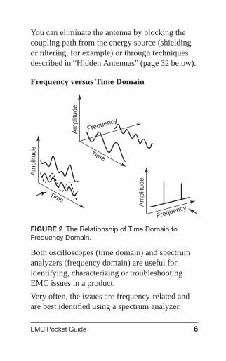
You can eliminate the antenna by blocking thecoupling path from the energy source (shieldingor filtering, for example) or through techniquesdescribed in “Hidden Antennas” (page 32 below).
Frequency versus Time Domain
Am
plitu
de
Time
Am
plitu
de
Time
Am
plitu
de
Frequency
Frequency
FIGURE 2 The Relationship of Time Domain toFrequency Domain.
Both oscilloscopes (time domain) and spectrumanalyzers (frequency domain) are useful foridentifying, characterizing or troubleshootingEMC issues in a product.
Very often, the issues are frequency-related andare best identified using a spectrum analyzer.
EMC Pocket Guide 6

Wyatt-4670090 wyat4670090-book May 23, 2013 14:40 7
According to the emission standards, be sure toset the resolution bandwidth to 9 kHz (or 10 kHz∗)for frequencies below 30 MHz and 120 kHz (or100 kHz∗) for frequencies from 30 to 1000 MHzand 1 MHz for frequencies 1 GHz and higher. Setthe video bandwidth the same, or wider for bestamplitude accuracy.
Oscilloscopes are very useful for identifyingresonances or ringing on digital or clock signals,as well as crosstalk issues.∗for analyzers lacking the “EMI bandwidths”.
Fourier Series & Transforms
Fourier analysis is a key tool in understanding thesignals that are encountered in EMC problemsand solution. Fourier series help provide adiscrete representation of time domain signals,while Fourier transforms are normally used toanalyze continuous signals.
Signal Spectra
The envelopes of the magnitude spectrum ofrectangular and trapezoidal pulses provide insightinto the spectral content of the waveformstypically encountered in EMC work.Additionally, pulse widths and duty cycles havea strong influence on spectral content and
EMC Pocket Guide 7

Wyatt-4670090 wyat4670090-book May 23, 2013 14:40 8
amplitudes. Knowing these factors, we canestimate what harmonics we need to protectagainst and at what levels.
x(t)
A
tr tf Tt
A/2 t
FIGURE 3 A typical trapezoidal waveform.
Figure 3 shows a trapezoidal waveform thatrepresents the output of the clock for digitalcircuits. By selecting the duty cycle, τ , the risetime, τr , and fall time, τf , appropriately, we cantailor our waveform to meet required performancecriteria, while minimizing the negative impact ofhigher order harmonics on adjacent analog anddigital circuits.
EMC Pocket Guide 8

Wyatt-4670090 wyat4670090-book May 23, 2013 14:40 9
−20 dB/decade
−40 dB/decade
0 dB/decade
Cm
f
2AtT
AtT
1pt
1ptr
FIGURE 4 Spectral bounds on trapezoidal waveform.
Referring to Figure 4, note that the duty cycle, τ ,determines the first breakpoint, while the risetime, τr , determines the second breakpoint.Figure 5 illustrates that the slower the rise time,the lower the magnitude of higher orderharmonics.
EMC Pocket Guide 9

Wyatt-4670090 wyat4670090-book May 23, 2013 14:40 10
Trapezoidalwaveform with 100MHz fundamental
and 0.1 ns rise time
Trapezoidalwaveform with 100MHz fundamental
and 0.5 ns rise time
1301201101009080706050403020
108 109 1010f (Hz)
−40 dB perdecade
−20 dB perdecade
Fundamentalfrequency
1ptr1
1ptr2
⏐Cm⏐(dBmV )
FIGURE 5 Magnitude spectra of trapezoidalwaveforms vs. rise times.
Figure 6 illustrates that reducing the duty cyclewill decrease the level of the magnitude envelope,again decreasing the level of higher orderharmonics.
In applying these principles, each individualsituation will have to be evaluated. However, ingeneral, there will be a −20 dB per decade drop inthe spectral magnitude after the first breakpoint,which will occur at 1/πτ , and then a drop of−40 dB per decade after the second breakpoint,
EMC Pocket Guide 10

Wyatt-4670090 wyat4670090-book May 23, 2013 14:40 11
Trapezoidal waveform with a10 MHz fundamental frequency
and a 50% duty cycle
Trapezoidal waveform with a10 MHz fundamental frequency
and a 25% duty cycle
1301201101009080706050403020
107 108 109f (Hz)
−40 dB perdecade
−20 dB perdecade
Fundamentalfrequency
The rise time is1 ns for bothwaveforms
1ptr
⏐Cm⏐(dBmV )
FIGURE 6 Magnitude spectra of trapezoidalwaveforms vs. duty cycle.
generally occurring at 1/πτr . Thus payingattention to both the rise/fall time and duty cyclewill pay significant dividends in controlling theharmonic content of clocks and oscillator circuits.
EMC Design
Cable Terminations
Cable shields should be connected (bonded) verywell to the metallic enclosure. If the shieldconnection is made directly to the PC board,
EMC Pocket Guide 11

Wyatt-4670090 wyat4670090-book May 23, 2013 14:40 12
common-mode noise currents (Icm) can flowdirectly through the enclosure and out the I/O orpower cable.
Enclosure
PC boardIcm
Icm
RE or CE
RE or CE
I/O Cable
CI, RI or ESD
G +
FIGURE 7
If the cable shield is connected in one place on theshielded enclosure, that’s called a “pigtail”connection and is nearly as bad. Ideally, connectthe cable shield in multiple places (360˚).
Enclosure
PC boardIcm
Icm
RE or CE
RE or CE
I/O Cable
CI, RI or ESD
G
+
FIGURE 8
A proper 360-degree bond to enclosure solvesmany EMC issues.
EMC Pocket Guide 12

Wyatt-4670090 wyat4670090-book May 23, 2013 14:40 13
Connector Bonding
Connector shields must be bonded in multipleplaces to the shielded enclosure. If this is notdone, then high-frequency common-modecurrents generated on the PC board may flow outthe I/O or power cables and cause radiatedemissions. Equally, cables may pick up outsideradiated or conducted sources, which can causecircuit upsets.
Gaps between connectorhousing and metal enclosure.
FIGURE 9 An example of poor bonding.
If connectors are unshielded, then all signal,return and power signals must be filtered on thePC board right at the connector. In many cases, ametal plate mounted closely under the PC board
EMC Pocket Guide 13

Wyatt-4670090 wyat4670090-book May 23, 2013 14:40 14
with one end turned up 90-degrees and bondedwell to all the I/O connector ground shells canprovide some protection. Note that the bondingmust be designed to deal with the harshestenvironment to which the system will be exposed.
Shielding
Never penetrate a shield with a wire or cablewithout using some form of cable shielding orfiltering. Common-mode noise currents on thePC board or internal electronic sub-assemblieswill couple to the wire or cable and travel outside,causing radiated or conducted emissions, or,conversely, susceptibility to external radiated orconducted fields.
Internalelectronics
I
I
Shield
Wire(cable)
FIGURE 10
EMC Pocket Guide 14

Wyatt-4670090 wyat4670090-book May 23, 2013 14:40 15
Calculating Shielding Effectiveness (SE):
Incident
Reflected
Transmitted
Transmittedincident
Transmitted
FIGURE 11
SE(dB) = A(dB) + R(dB) + M(dB)
Absorption LossAdB = 20 log10 et/δ
AdB = 20t/δ log10 e
AdB = 8.6859t/δ
AdB = 131.4t√
f μr σr (where t is in m)
AdB = 3.338t√
f μr σr (where t is in inches)
Note that for every skin depth, δ, A = 8.6859 dB
EMC Pocket Guide 15

Wyatt-4670090 wyat4670090-book May 23, 2013 14:40 16
Reflection Loss
RdB = 168 + 10 log10
(σr
μr f
)
Multiple Reflection Loss
MdB = 20 log10
∣∣∣∣∣1 −(
η0 − η̂
η0 + η̂
)2
e−2t/δe− j2βt
∣∣∣∣∣MdB ∼= 20 log10
∣∣1 − e2t/δe− j2t/δ∣∣
For most good shields, M is zero.
SE versus Slot Length
Freq (MHz) 20 dB SE 40 dB SE
10 100 cm 19 cm
30 75 cm 5 cm
100 15 cm 1.5 cm
300 5 cm 0.5 cm
500 2.5 cm —
1000 1.5 cm —
For example, a 6-inch slot only has an effectiveshielding effectiveness (SE) of 20 dB at 100 MHz.Harmonic frequencies not on the chart may beinterpolated.
EMC Pocket Guide 16

Wyatt-4670090 wyat4670090-book May 23, 2013 14:40 17
Most practical metallic enclosures (with requiredapertures, realistic seams, and ventilation holes)averages 20 to 30 dB SE. As the frequencyincreases, it becomes increasingly important toensure any holes and seams are minimized in yourenclosure.
Leakages may be measured with either E-field orH-field probes. The length of major leakagesshould be marked at the end points and thenanalyzed for potential resonances at criticalharmonic frequencies using the formulas onpage 32 or the Frequency versus Wavelength tableon page 34. For example, a seam with leakage15 cm long is 1/4-wavelength at 500 MHz. For a500 MHz harmonic, you’d want no more than2.5 cm leakage for 20 dB SE.
Common PC Board Issues
Discontinuous Return Paths
Most PC board problems can be traced todiscontinuous signal return paths. This isbecoming more of an issue with the increasingclock frequencies used today. This is also a majorcause of common-mode emissions.
1. High-frequency signals travel down the traceto the load and then return immediately underthat trace, due to mutual coupling.
EMC Pocket Guide 17

Wyatt-4670090 wyat4670090-book May 23, 2013 14:40 18
Printed circuit board
− +− +− +− +
Source Load
Gap in returnplane Source
current
Sourcecurrent
Returncurrent
Returncurrent− +
− +− +− + V = M(di/dt)
M
V
FIGURE 12
a. All too often that return path is interruptedby a discontinuity, such as a gap or slot inthe return or power planes (Figure 12).
b. Solution: Examine the signal return andpower plane layers for gaps and slots.
2. The signal trace passes through a via andchanges reference planes.a. Add extra vias or stitching capacitors for
return currents when switching referenceplanes (Figure 13).
EMC Pocket Guide 18

Wyatt-4670090 wyat4670090-book May 23, 2013 14:40 19
Source
Load
Via
Plane 1
?
Signal Layer
Signal Layer
Plane 2
FIGURE 13
Signal
Return
Digital plane
IC1 IC2
Analog plane
FIGURE 14
3. Routing a clock (or any) trace over anunrelated (e.g., analog) plane can cause noisecoupling to sensitive circuitry (Figure 14).a. High-frequency clock signals can couple
into the analog circuitry (crosstalk).b. Because the return path is now forced out
around the unrelated plane, this causescommon-mode currents and resultingradiated emissions.
EMC Pocket Guide 19
Wyatt-4670090 wyat4670090-book May 23, 2013 14:40 20
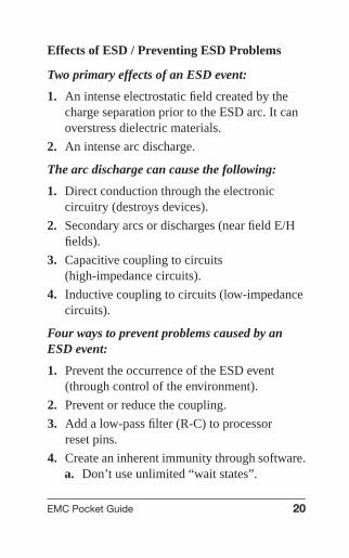
Effects of ESD / Preventing ESD Problems
Two primary effects of an ESD event:
1. An intense electrostatic field created by thecharge separation prior to the ESD arc. It canoverstress dielectric materials.
2. An intense arc discharge.
The arc discharge can cause the following:
1. Direct conduction through the electroniccircuitry (destroys devices).
2. Secondary arcs or discharges (near field E/Hfields).
3. Capacitive coupling to circuits(high-impedance circuits).
4. Inductive coupling to circuits (low-impedancecircuits).
Four ways to prevent problems caused by anESD event:
1. Prevent the occurrence of the ESD event(through control of the environment).
2. Prevent or reduce the coupling.
3. Add a low-pass filter (R-C) to processorreset pins.
4. Create an inherent immunity through software.a. Don’t use unlimited “wait states”.
EMC Pocket Guide 20

Wyatt-4670090 wyat4670090-book May 23, 2013 14:40 21
b. Use “watchdog” routines to restart aproduct.
c. Use parity bits, checksums, or errorcorrecting codes to prevent storage of baddata.
d. All inputs should be latched and strobed –don’t leave any floating.
EMC Measurements
Troubleshooting with Current Probes
0.1 1 10
Frequency (MHz)
100 1000
Transfer im
pedance dBabove 1 O
hm (± 2 dB
)
+20
+10
0
−10
−20
−30
FIGURE 15 A plot of transfer impedance for a typicalcurrent probe (Fischer Custom CommunicationsF-33-1 probe used).
EMC Pocket Guide 21

Wyatt-4670090 wyat4670090-book May 23, 2013 14:40 22
By clamping a current probe around a cable andusing the plot of transfer impedance, you cancalculate the common-mode current in that cableversus frequency. By knowing the current, youcan plug it into the equation for the E-field(dBμV/m) and compare to the radiated emissionlimit. See “Commonly Used Equations” (page 38).
Icm(dBμA) = Vterm(dBμV) − Zt(dB�)
Troubleshooting with Antennas
1m Test distance
BroadbandEMI antenna
Preamp(If required)
Spectrum analyzer
EUTE-field (V/m)
FIGURE 16 Setup for radiated emissionstroubleshooting.
EMC Pocket Guide 22

Wyatt-4670090 wyat4670090-book May 23, 2013 14:40 23
To troubleshoot radiated emissions, you’ll need tofind some space at least 3 m from the nearestreflective structure, such as a parking lot, largeconference room, or basement.
Set up the antenna about 1 m from the EUT andconnect the antenna to a spectrum analyzer, via abroadband preamp if the signal requires boosting.You’ll need to take the 3 m (or 10 m) limits andadd 10 dB (or 20 dB) to them to convert to 1 mtest distance limits (see Figure 17). Becauseyou’re partly measuring in the near field, thesecomputed test limits may not be completelyaccurate but should at least indicate major “redflags”. The antenna manufacturer will provide achart of Antenna Factors (AF).
If using a log-periodic antenna, understand theactive element will change position withfrequency: higher frequencies will be closer than1 m, lower frequencies farther.
Use these extrapolated FCC/CISPR radiatedemissions limits when troubleshooting with anantenna positioned 1 m away from the EUT.
EMC Pocket Guide 23

Wyatt-4670090 wyat4670090-book May 23, 2013 14:40 24
FCC-A FCC/CISPR-A
FCC/CISPR-A
1010
20
30
40
dB m
V/m
50
60
70
100
Frequency (MHz)
23088 216
1000
FCC/CISPR-A
FCC/CISPR-AFCC-B
CISPR-B
CISPR-A
FIGURE 17 Radiated emission limits extrapolated toa 1 m test distance.
Use this formula to determine the E-field(dBμV/m) at the antenna terminals:
E-Field (dBμV/m) = SpecAnalyzer(dBμV)
− PreampGain(dB) + CoaxLoss(dB)
+ AttenuatorLoss(dB) + AntFactor(dB)
EMC Pocket Guide 24

Wyatt-4670090 wyat4670090-book May 23, 2013 14:40 25
EMC Standards
Common Basic EMC Standards
Type Standard Test/Scope
Commercial CISPR 11 ISM Equipment
CISPR 22 ITE Equipment
CISPR 16 Methods of Measurement
IEC 61000-3-2 Harmonics
IEC 61000-3-3 Flicker
IEC 61000-4-2 Electrostatic Discharge (ESD)
IEC 61000-4-3 Radiated Immunity
IEC 61000-4-4 Electrically Fast Transient (EFT)
IEC 61000-4-5 Surge (Lightning)
IEC 61000-4-6 Conducted Immunity
IEC 61000-4-8 Magnetic Immunity
IEC 61000-4-11 Dips, Interrupts, Voltage Variations
FCC Part 15B ITE Equipment
ANSI C63.4 Methods of Measurement
Medical IEC 60601-1-2 Medical Products
Automotive SAE J1113 Automotive EMC
Military MIL STD 461F EMC Test Requirements
Aerospace DO-160 EMC Test Requirements (Aircraft)
SAE ARP5412B Aircraft Lightning Environment &Related Test Waveforms
SAE ARP5416A Aircraft Lightning Test Methods
EMC Pocket Guide 25

Wyatt-4670090 wyat4670090-book May 23, 2013 14:40 26
In general, the emission limits are more restrictivefor residential environments and less restrictivefor industrial environments. Immunity, on theother hand, is usually more restrictive forindustrial environments.
USA
Class A
Class B
Emissionsincrease
non-residential
residential
industrial
residential,commercial,
light industrial
EMC environmentEU+
ImmunitydisturbancesFIGURE 18
FCC/CISPR 10 m Limits (RE)
88
70
FCC B
FCC A
CISPR A
CISPR B
960
60
50
40
30
20
1010 100
Frequency (MHz)
Fie
ld s
tren
gth
(dB
mV
/m)
1000
216
230
FIGURE 19
EMC Pocket Guide 26

Wyatt-4670090 wyat4670090-book May 23, 2013 14:40 27
FCC/CISPR Limits (CE)
90
80
70
60
50
40
300.1 0.45 1 10
Frequency (MHz)
100
Vol
tage
(dB
mV
)
Class A quasi-peak limit
Class B quasi-peak limit
Class B average limit
Class A average limit
FIGURE 20
Class A – Industrial/commercial environment
Class B – Residential environment
Using Decibels
Working with dB
The decibel is always a ratio. . .
• Power Gain = Pout/Pin• Power Gain (dB) = 10 log (Pout/Pin)• Voltage Gain (dB) = 20 log (Vout/Vin)• Current Gain (dB) = 20 log (Iout/Iin)
EMC Pocket Guide 27

Wyatt-4670090 wyat4670090-book May 23, 2013 14:40 28
We commonly work with. . .
• dBm (referenced to 1 mW)• dBμV (referenced to 1 μV)• dBμA (referenced to 1 μA)
Power Ratios
3 dB = double (or half) the power
10 dB = 10X (or /10) the power
Voltage/Current Ratios
6 dB = double (or half) the voltage/current
20 dB − 10X (or /10) the voltage/current
dBm, dBμV, dBμA (conversion)
Log ↔ Linear Voltage
Volts to dBV dBV = 20 log(V)
Volts to dBμV dBμV = 20 log(V) + 120dBV to Volts V = 10(dBV/20)
dBμV to Volts V = 10((dBμV−120)/20)
dBV to dBμV dBμV = dBV + 120dBμV to dBV dBV = dBμV − 120
Note: For current relationships, substitute A for V
Log identities:
If Y = log(X), then X = 10Y
Log 1 = 0
EMC Pocket Guide 28

Wyatt-4670090 wyat4670090-book May 23, 2013 14:40 29
Log of numbers > 1 are positive
Log of numbers < 1 are negative
The log (A∗B) = log A + log B
The log (A/B) = log A − log B
The log of An = n∗log A
dBm to dBμV
(Assuming a 50-Ohm system)
dBm dBμV
20 127
10 117
0 107
−10 97
−20 87
−30 77
−40 67
−50 57
−60 47
−70 37
−80 27
−90 17
−100 7
To convert dBm to dBμV, use:
dBμV = dBm + 107
EMC Pocket Guide 29

Wyatt-4670090 wyat4670090-book May 23, 2013 14:40 30
Power Ratios (dB)
Unit Power Voltage or Current
0.1 −10 dB −20 dB
0.2 −7.0 dB −14.0 dB
0.3 −5.2 dB −10.5 dB
0.5 −3.0 dB −6.0 dB
1 0 dB 0 dB
2 3.0 dB 6.0 dB
3 4.8 dB 9.5 dB
5 7.0 dB 14.0 dB
7 8.5 dB 16.9 dB
8 9.0 dB 18.1 dB
9 9.5 dB 19.1 dB
10 10 dB 20 dB
20 13.0 dB 26.0 dB
30 14.8 dB 29.5 dB
50 17.0 dB 34.0 dB
100 20 dB 40 dB
1,000 30 dB 60 dB
1,000,000 60 dB 120 dB
Double the value and it adds 3 dB to power, 6 dBto voltage and current. Halving the value subtracts3 dB from power, 6 dB from voltage and current.
EMC Pocket Guide 30

Wyatt-4670090 wyat4670090-book May 23, 2013 14:40 31
Multiplying 10X the value and it adds 10 dB topower, 20 dB to voltage and current. Dividing by10X the value subtracts 10 dB from power, 20 dBfrom voltage and current.
Frequency versus Wavelength
Most EMC issues occur in the range 9 kHzthrough 6 GHz. Conducted emissions tend tooccur below 30 MHz and radiated emissions tendto occur above 30 MHz.
The Electromagnetic Spectrum
Band Freq Range Wavelength
HF 3–30 MHz 100 m – 10 m
VHF 30–300 MHz 10 m – 1 m
UHF 300–1000 MHz 1 m – 30 cm
L 1–2 GHz 30 cm – 15 cm
S 2–4 GHz 15 cm – 7.5 cm
C 4–8 GHz 7.5 cm – 3.75 cm
X 8–12 GHz 3.75 cm – 2.5 cm
Ku 12–18 GHz 2.5 cm – 1.67 cm
K 18–27 GHz 1.67 cm – 1.11 cm
Ka 27–40 GHz 1.11 cm – 0.75 cm
EMC Pocket Guide 31

Wyatt-4670090 wyat4670090-book May 23, 2013 14:40 32
For more detail on the users of the EM Spectrumreview the chart at:
http://www.ntia.doc.gov/files/ntia/publications/spectrum wall chart aug2011.pdf. Note that thisis the spectrum allocation chart for the USA.Other countries may have similar allocationcharts.
Hidden Antennas
An important concept to grasp is the electricaldimension of an electromagnetic radiatingstructure (we sometimes call these “antennas”).This is expressed in terms of wavelength (λ).
In a lossless medium (free space),
Wavelength (λ) = v/ f
where v = velocity of propagation and f =frequency (Hz).
In free space v = vo ≈ 3 × 10⁸ m/s (approx.speed of light)
Easy to remember formulas for wavelength:
λ(m) = 300/ f (MHz)
λ/2 (ft) = 468/ f (MHz)
EMC Pocket Guide 32

Wyatt-4670090 wyat4670090-book May 23, 2013 14:40 33
This becomes important when it comes toidentifying potential radiating structures – socalled “hidden antennas” – of the product orsystem under test. These structures couldinclude:
1. Cables (I/O or power)
2. Seams/slots in shielded enclosures
3. Apertures in enclosures
4. Poorly bonded sheet metal (of enclosures)
5. PC boards (especially narrow ones)
6. Internal interconnect cables
7. Heat sinks
8. Daughter boards
9. Peripheral equipment connected to the EUT
10. Power plane “patch” over a ground plane
For example, as a cable or slot approaches 1/4wavelength (or a multiple) at the frequency ofconcern, it becomes an efficient transmitting orreceiving antenna. Conversely, 1/20th wavelengthmakes a poor antenna. Use the following charts asfor help.
EMC Pocket Guide 33

Wyatt-4670090 wyat4670090-book May 23, 2013 14:40 34
Frequency versus Wavelength (air)
Freq Wavelength 1/4 1/20th
10 Hz 30,000 km 7,500 km 1,500 km
60 Hz 5,000 km 1,250 km 250 km
400 Hz 750 km 187.5 km 37.5 km
1 kHz 300 km 125 km 37.5 km
10 kHz 30 km 7.5 km 1.5 km
100 kHz 3 km 750 m 150 m
1 MHz 300 m 75 m 15 m
10 MHz 30 m 7.5 m 1.5 m
100 MHz 3 m 75 cm 15 cm
300 MHz 100 cm 25 cm 5 cm
500 MHz 60 cm 15 cm 3 cm
1 GHz 30 cm 7.5 cm 1.5 cm
10 GHz 3 cm .75 cm .15 cm
A slot or cable of 1/4 wavelength (or multiple) canmake a good antenna at the frequency of concern.
A slot or cable of 1/20th wavelength makes a verypoor antenna at the frequency of concern.
EMC Pocket Guide 34

Wyatt-4670090 wyat4670090-book May 23, 2013 14:40 35
Frequency versus Wavelength (FR-4)
Freq Wavelength 1/4 1/20th
10 MHz 18 m 4.5 m 90 cm
25 MHz 7.2 m 1.8 m 36 cm
50 MHz 3.6 m 90 cm 18 cm
100 MHz 1.8 m 45 cm 9 cm
200 MHz 90 cm 22.5 cm 4.5 cm
300 MHz 60 cm 15 cm 3 cm
400 MHz 45 cm 11 cm 2.25 cm
500 MHz 36 cm 9 cm 1.8 cm
600 MHz 30 cm 7.5 cm 1.5 cm
700 MHz 25.7 cm 6.4 cm 1.3 cm
800 MHz 22.5 cm 5.6 cm 1.1 cm
900 MHz 20 cm 5 cm 1 cm
1000 MHz 18 cm 4.5 cm 0.9 cm
This is just an approximate length, due tovariations in the velocity constant of FR-4fiberglass-epoxy.
A velocity factor of 0.6 was used in thecalculation, but it can vary from 0.4 to 0.8.Basically, a quarter-wave trace or PC board lengthwill be shorter than in free space by the velocityfactor.
EMC Pocket Guide 35

Wyatt-4670090 wyat4670090-book May 23, 2013 14:40 36
Commonly Used Equations
Ohms Law (formula wheel)
V 2
R
V 2
P P I2
PI
VI
VR
PV
PR
I = current R = resistance
P = power
P × R
V = voltage
wattsP
voltsV
Iamps
Rohms
√⎯⎯⎯⎯⎯V × I
R × I 2
R × I
√⎯
FIGURE 21 Ohms Law “formula wheel” forcalculating resistance (R), voltage (V), current (I) orpower (P), given at least two of the other values.
VSWR and Return Loss
VSWR given forward/reverse power
VSWR =1 +
√Prev
Pfwd
1 −√
Prev
Pfwd
EMC Pocket Guide 36

Wyatt-4670090 wyat4670090-book May 23, 2013 14:40 37
VSWR given reflection coefficient
VSWR = 1 + ρ
1 − ρ
Reflection coefficient, ρ, given Z1, Z2 Ohms
ρ =∣∣∣∣ Z1 − Z2
Z1 + Z2
∣∣∣∣Reflection coefficient, ρ, given fwd/rev power
ρ =√
Prev
Pfwd
Return Loss, given forward/reverse power
RL(dB) = 10 log
(Pfwd
Prev
)
Return Loss, given VSWR
RL(dB) = −20 log
(VSWR − 1
VSWR + 1
)
Return Loss, given reflection coefficient
RL(dB) = −20 log (ρ)
Mismatch Loss given forward/reverse power
ML(dB) = 10 log
(Pfwd
Pfwd − Prev
)
EMC Pocket Guide 37

Wyatt-4670090 wyat4670090-book September 19, 2013 14:5 38
Mismatch Loss, given reflection coefficient
ML(dB) = −10 log(
1 − ρ2)
E-Field from Differential-Mode Current
|ED,max| = 2.63 × 10⁻¹⁴ |ID | f 2 L S
d
ID = differential-mode current in loop (A)F = frequency (Hz)L = length of loop (m)S = spacing of loop (m)d = measurement distance (3m or 10m, typ.)
(Assumption that the loop is electrically smalland measured over a reflecting surface)
E-Field from Common-Mode Current
|EC,max| = 1.257 × 10⁻⁶ |IC | f L
dIC = common-mode current in wire (A)F = frequency (Hz)L = length of wire (m)d = measurement distance (3m or 10m, typ.)
(Assumption that the wire is electrically short)
EMC Pocket Guide 38

Wyatt-4670090 wyat4670090-book May 23, 2013 14:40 39
Resonance (rectangular enclosure)
Height (a)
Depth (b)
Width (c)
FIGURE 22 A rectangular enclosure can resonate ifexcited.
( f )mnp = 1
2√
εμ
√(m
a
)2+
(n
b
)2+
( p
c
)2
Where: ε = material permittivity, μ = materialpermeability and m, n, p are integers and a, b, care the height, depth and width.
Cavity resonance can only exist if the largestcavity dimension is greater, or equal, to one-halfthe wavelength. Below this cutoff frequency,cavity resonance cannot exist. In thisconfiguration (where a < b < c), the TE011 modeis dominant, because it occurs at the lowestfrequency at which cavity resonance can exist.
EMC Pocket Guide 39

Wyatt-4670090 wyat4670090-book May 23, 2013 14:40 40
Resonance (circular enclosure)
h
a
FIGURE 23 Circular resonant cavity.
For
a ≥ h/2.03
For a circular cavity
f = 2.4049/2πa√
μ0ε0
Example: for a = 9 cm and h = 6 cm (a typicalcookie tin):
f = 2.4049
2π(0.09)√
(8.854 × 10⁻¹²)(4π × 10−7)
f = 1, 275 MHz
Antenna (Far Field) Relationships
Gain, dBi to numeric
Gainnumeric = 10(dBi/10)
EMC Pocket Guide 40

Wyatt-4670090 wyat4670090-book May 23, 2013 14:40 41
Gain, numeric to dBi
dBi = 10 log (Gainnumeric)
Antenna Factor Equations (based on a 50 �
system and using polarization matched antennas)
AF(dB/m) = E(dBμV/m) − Vr(dBμV)
Where:
AF = Is the antenna factor of the measuringantenna (dB/m)E = Field strength at the antenna in dBμV/mVr = Output voltage from receiving antenna indBμV
Gain (dBi) to Antenna Factor
AF = 20 log[f(MHz)] − G(dBi) − 29.79 dB
Field Strength given Antenna Factor and spectrumanalyzer output adjusted for system losses (Vo)
E(dBμV/m) = AF(dB/m) + Vo(dBμV)
Where:
AF is the antenna factor of the measuring antenna(dB/m)E is the unknown or measured electric fieldstrength
EMC Pocket Guide 41

Wyatt-4670090 wyat4670090-book May 23, 2013 14:40 42
Vo is the adjusted spectrum analyzer output(calibrated for cable & connector, or system,losses)
Field strength given Power (watts), antenna gain(numeric) and distance (meters)
V/m =√
30PG
d
Field strength, given Power (watts), antenna gain(dBi) and distance (meters)
V/m =√
30P10(dBi/10)
d
Transmit power required, given desired V/m,antenna gain (numeric) and distance (meters)
Ptransmit = ((V/m)d)2
30G
Transmit power required, given desired V/m,antenna gain (dBi) and distance (meters)
Ptransmit = ((V/m)d)2
30(10(dBi/10)
EMC Pocket Guide 42

Wyatt-4670090 wyat4670090-book May 23, 2013 14:40 43
Wave Impedance versus Distance
0.110
30
100
Zw
(ohm
s)
300
1,000
3,000
10,000
1.0 10
Low impedance(magnetic) field
High impedance(electric) field
Far fieldNear field
Zo = 120p = 377Ω
Distance from source d (increments of r )= l2p
FIGURE 24 Variation of wave impedance versusdistance from the source.
The near-field far-field transition occurs at about1/6 wavelength.
EMC Pocket Guide 43

Wyatt-4670090 wyat4670090-book May 23, 2013 14:40 44
E-Field Levels versus Transmitter Pout
Pout (W) V/m at 1 m V/m at 3 m V/m at 10 m
1 5.5 1.8 0.6
5 12.3 4.1 1.2
10 17.4 5.8 1.7
25 27.5 9.2 2.8
50 38.9 13.0 3.9
100 55.0 18.3 5.5
1000 173.9 58.0 17.4
Assuming the antenna gain is 1.
Device Approx Freq Max Power Approx V/m at 1 m
Citizens 27 MHz 5 W 12Band
FRS 465 MHz 500 mW 4
GMRS 465 MHz 1 to 5 W 5.5 to 12
3G Mobile 830 MHz / 400 mW 3.5Phone 1.8 GHz
EMC Pocket Guide 44

Wyatt-4670090 wyat4670090-book May 23, 2013 14:40 45
These license-free devices may be used todetermine radiated immunity of an EUT byholding them close to the EUT or I/O or powercable. GMRS radios require a license.
Miscellaneous Information
Galvanic Series
The galvanic and triboelectric series are oftenconfused but are useful for different purposes.
The galvanic series allows us to determine whichof two metals in an electrolyte (or some otherreactive environment) will experience galvaniccorrosion, with the less noble (sacrificial) metalprotecting the other, more noble metal. This isalso known as cathodic protection. Thisprotection is dependent upon the electrolyte,surface finish and material composition. It isimportant to understand bonding and corrosion ofenclosures, especially in harsh environments.
EMC Pocket Guide 45

Wyatt-4670090 wyat4670090-book May 23, 2013 14:40 46
1. For units which will be subjected to salt spray or salt water, metal should bechosen where the potential difference is less than 0.25V.
2. Where it is possible the unit will be subjected to high humidity that is not saltladen, then the potential difference should not exceed 0.45V.
.075
1.05
1.05
1.36
1.30
1.39
1.54
1.58
1.58
1.67
1.78
.029
.029
.060
.029
0.65
0.78
0.82
0.82
0.91
1.02
0.01
0.31
0.32
0.34
0.50
0.55
0.56
0.64
0.75
0.31
0.32
0.34
0.50
0.55
0.56
0.64
0.75
0.01
0.03
0.22
0.24
0.25
0.35
0.44
0.02
0.20
0.23
0.25
0.32
0.43
0.02
0.11
0.12
0.20
0.31
0.02
0.03
0.11
0.22
0.01
0.02
0.21
0.08
0.19 0.11
Anode
Cathode
Zinc
Aluminum
Cadmium
Tin
Iron, steel
Chromium
Brass
Copper/bronze
Nickel/monel
Stainless steel
Silver
Mag
nes
ium
Zin
c
Alu
min
um
Cad
miu
m
Tin
Iro
n, s
teel
Ch
rom
ium
Bra
ss
Co
pp
er, b
ron
ze
Nic
kel,
mo
nel
Sta
inle
ss s
teel
FIGURE 25 Galvanic series – minimize the differentialvoltage.
Triboelectric Series
The triboelectric series determines how differentmaterials will accept or give up electrons whenrubbed together, to determine which materialbecomes more positive and which becomes morenegative.
EMC Pocket Guide 46

Wyatt-4670090 wyat4670090-book May 23, 2013 14:40 47
(+) POSITIVE END OF SERIES (lower workfunction)
AirHuman Skin
AsbestosGlassNylonWoolLeadSilk
AluminumPaperCottonSteel
Hard rubberEpoxy-FiberglassNickel & copperBrass & silver
Synthetic rubberOrlonSaran
PolyethyleneTeflon
Silicone rubber
(−) NEGATIVE END OF SERIES (higherwork function)
Actual charge transfer depends on several factors,including specific materials, surface finish,temperature, humidity, etc.
EMC Pocket Guide 47

Wyatt-4670090 wyat4670090-book May 23, 2013 14:40 48
Useful Software
PC
LTspice (free from Linear Technology)
Various PC board layout viewers (refer to layoutmanufacturers)
Macintosh
EasyDraw (for producing schematics, drawingsand graphics)
McCAD (reviewing PC board layouts)
MacSpice (spice simulator)
iPad/iPhone
dB Calculator (Rohde & Schwarz)
Field Strength & Power Estimator (Rohde &Schwarz)
Interference Hunter (Rohde & Schwarz)
Aviation RF Link (Rohde & Schwarz)
Wireless Communication Calculator (Rohde &Schwarz)
iCircuit (schematic capture and analysis)
LineCalc (coax cable loss and electrical length)
Electronic TB (multitude of handy electronicdesign aids)
EMC Pocket Guide 48

Wyatt-4670090 wyat4670090-book May 23, 2013 14:40 49
μWave Calc (Agilent Technologies μW/RFcalculator)
PCB Calc (Agilent Technologiesmicrostrip/stripline calculator)
RF Tools (Huber+Suhner RF tools for reflection,frequency/wavelength, signal delay, impedanceand dB)
RF Toolbox Pro (a comprehensive collection ofRF-related tools and references)
E Formulas (multitude of electronics-relatedformulas and calculators)
Circuit Lab (analyzes DC/AC linear andnon-linear and transient circuits)
dB Calc (calculates/converts dB)
EE Toolkit (another well-done component andcircuits reference)
Buyer’s Guide (ITEM buyer’s guide to EMCproducts and services)
Directives (listing of EU directives with links tothe document)
Calculator Pro (a good EE calculator)
Power One SE Calculator (engineering calculatorwith equation solver)
Spicy (well-done schematic capture and spiceanalysis)
EMC Pocket Guide 49

Wyatt-4670090 wyat4670090-book May 23, 2013 14:40 50
Spicy SWAN (a comprehensive Spice and“simulation by wave analysis” is a step up fromSpicy in that it focuses more on signalpropagation effects. Useful for high-frequencytransmission line analysis.
Android
dB Calculator (Rohde & Schwarz)
Field Strength & Power Estimator (Rohde &Schwarz)
Interference Hunter (Rohde & Schwarz)
Aviation RF Link (Rohde & Schwarz)
RF & Microwave Toolbox (by Elektor, acollection of RF tools)
RF Engineering Tools (by Freescale, acompilation of calculators and converters for RFand microwave design)
RF Calc (by NXP, series/parallel, unitconversions, thermal resistance)
RF Calculator (by Lighthorse Tech, wavelength,propagation velocity, etc.)
EMC & Radio Conversion Utility (by TRACGlobal, converters, path loss, EIRP,wavelength, etc.)
EMC Pocket Guide 50

Wyatt-4670090 wyat4670090-book May 23, 2013 14:40 51
References
Books
ARRL, The RFI Handbook, 3rd edition, 2010.
Eric Bogatin, Signal Integrity - Simplified,Prentice Hall PTR, 2004.
Stephen H. Hall, Garrett W. Hall & James A.McCall, High-Speed Digital System Design: AHandbook of Interconnect Theory and DesignPractices, John Wiley & Sons, 2000.
Howard W. Johnson & Martin Graham,High-Speed Digital Design: A Handbook of BlackMagic, Prentice Hall PTR, 1993.
Howard W. Johnson & Martin Graham,High-Speed Signal Propagation: Advanced BlackMagic, Prentice Hall PTR, 2003.
Elya B. Joffe and Kai-Sang Lock, Grounds forGrounding: A Circuit to System Handbook,Wiley, 2010.
Kenneth L. Kaiser, Handbook of ElectromagneticCompatibility, CRC Press, 2005.
Ralph Morrison, Grounding and ShieldingCircuits and Interference, 5th ed.,Wiley-Interscience, 2007.
Henry W. Ott, Electromagnetic CompatibilityEngineering, John Wiley & Sons, 2009.
EMC Pocket Guide 51

Wyatt-4670090 wyat4670090-book May 23, 2013 14:40 52
Clayton R. Paul, Introduction to ElectromagneticCompatibility, 2nd ed., Wiley-Interscience, 2006.
Lee W. Ritchey and John Zasio, Right the FirstTime – A Practical Handbook on High SpeedPCB and System Design, Speeding Edge, Volume1 (2003) and Volume 2 (2006). Available atwww.speedingedge.com.
Doug Smith, High Frequency Measurements andNoise in Electronic Circuits, Van Nostrand 1993.
Steven H. Voldman, ESD: Physics and Devices,John Wiley & Sons, Ltd, 2004.
Würth Electronics, Brander, T. et al., Trilogy ofMagnetics: Design Guide for EMI Filter Design,SMPS and RF Circuits, 4th ed., Würth ElektronikeiSos GmbH & Co., 2010.
Brian Young, Digital Signal Integrity: Modelingand Simulation with Interconnects and Packages,Prentice Hall PTR, 2001.
EMC Magazines
InCompliance Magazine (www.incompliancemag.com)
Interference Technology(www.interferencetechnology.com)
EMC Pocket Guide 52

Wyatt-4670090 wyat4670090-book May 23, 2013 14:40 53
IEEE Electromagnetic Compatibility Magazine,published by the IEEE EMC Society,(www.emcs.org/newsletters.html)
Electromagnetic News Report (www.7ms.com)
Safety & EMC, China (www.semc.cesi.cn)
Compliance Engineering (stopped publication in2006, but still available at www.ce-mag.com)
The EMC Journal, UK, (www.compliance-club.com)
EMC Organizations
Automotive EMC (www.autoemc.net)
IEEE EMC Society (www.ewh.ieee.org/soc/emcs/)
ESD Association (www.esd.org)
iNARTE (International Association for Radio,Telecommunications and Electromagnetics)(www.narte.org)
EMC Standards Organizations
ANSI (American National Standards Institute)(www.ansi.org)
ANSI Accredited C63 (www.c63.org)
IEEE Standards Association (www.standards.ieee.org)
EMC Pocket Guide 53

Wyatt-4670090 wyat4670090-book May 23, 2013 14:40 54
IEEE EMC Society Standards DevelopmentCommittee (SDCOM) (http://www.emcs.org/standards/index.html)
SAE (Society of Automotive Engineers)(www.sae.org/)
SAE EMC Standards Committee(www.sae.org/standards/)
EMCIA (Electromagnetic Compatibility IndustryAssociation, UK) (www.emcia.org)
IEC (International Electrotechnical Commission)(www.iec.ch/index.htm)
CISPR (International Special Committee onRadio Interference) (http://www.iec.ch/emc/iec emc/iec emc players cispr.htm)
APLAC (Asia Pacific Laboratory AccreditationCooperation) (www.aplac.org)
CSA (Canadian Standards Association)(www.csa.ca)
FCC (Federal Communications Commission, US)(www.fcc.gov)
IBIS (Input/Output Buffer Specification)(www.eigroup.org/ibis/default.html)
ISO (International Organization for Standards)(www.iso.org/iso/home.html)
VCCI (Voluntary Control Council forInterference, Japan) (www.vcci.jp/vcci e/)
EMC Pocket Guide 54

Wyatt-4670090 wyat4670090-book May 23, 2013 14:40 55
LinkedIn Groups
LinkedIn is the world’s largest professional’snetworking and discussion forum. Severaldiscussion groups related to EMC are listed here.Create your free profile at: www.linkedin.com.
• Aircraft and Spacecraft ESD/EMI.EMC Issues• Automotive EMC Troubleshooting Experts• EMC – Electromagnetic Compatibility• EMC Experts• EMC Jobs• EMC Testing and Compliance• EMI and EMC Consultants• Electromagnetic Compatibility Automotive
Group• Electromagnetic Compatibility Forum• Electromagnetics and Spectrum Engineering
Group• ESD Experts• iNARTE• Military EMC Forum• RTCA/DO-160 Experts
Common Symbols◦A Angstrom, unit of length, one ten bil-
lionth of a meterA Amperes, unit of electrical currentAC Alternating Current
EMC Pocket Guide 55

Wyatt-4670090 wyat4670090-book May 23, 2013 14:40 56
AM Amplitude modulatedcm Centimeter, one hundredth of a meterdBm dB with reference to 1 mWdBμA dB with reference to 1 μAdBμV dB with reference to 1 μVDC Direct CurrentE “E” is the electric field component of an
electromagnetic field.E/M Ratio of the electric field (E) to the mag-
netic field (H), in the far-field this is thecharacteristic impedance of free space, ap-proximately 377 �
EM ElectromagneticEMC Electromagnetic compatibilityEMI Electromagnetic InterferenceFM Frequency modulatedGHz Gigahertz, one billion Hertz
(1,000,000,000 Hertz)H “H” is the magnetic field component of an
electromagnetic field.Hz Hertz, unit of measurement for frequencyI Electric currentkHz Kilohertz, one thousand Hertz (1000
Hertz)λ Lambda, symbol for wavelength, distance
a wave travels during the time period nec-essary for one complete oscillation cycle
EMC Pocket Guide 56

Wyatt-4670090 wyat4670090-book May 23, 2013 14:40 57
MHz Megahertz, one million Hertz(1,000,000 Hertz)
μm Micrometer, unit of length, one millionthof an meter (0.000001 meter)
m Meter, the fundamental unit of length inthe metric system
mil Unit of length, one thousandth of an inchmW Milliwatt (0.001 Watt)mW/cm2 Milliwatts per square centimeter (0.001
Watt per square centimeter area), a unitfor power density, one mW/cm2equalsten W/m2
Pd Power density, unit of measurement ofpower per unit area (W/m2or mW/cm2)
R ResistanceRF Radio FrequencyRFI Radio Frequency InterferenceV Volts, unit of electric voltage potentialV/m Volts per meter, unit of electric field
strengthW/m2 Watts per square meter, a unit for power
density, one W/m2 equals 0.1 mw/cm2
� Ohms, unit of resistance
Ref: ANSI/IEEE 100-1984, IEEE StandardDictionary of Electrical and Electronics Terms,1984.
EMC Pocket Guide 57

Wyatt-4670090 wyat4670090-book May 23, 2013 14:40 58
EMC Acronyms
AF (Antenna Factor) – The ratio of the receivedfield strength to the voltage at the terminals of areceiving antenna. Units are 1/m.
ALC (Absorber-Lined Chamber) – A shieldedroom with RF-absorbing material on the wallsand ceiling. In many cases, the floor is reflective.
AM (Amplitude Modulation) – A technique forputting information on a sinusoidal carrier signalby varying the amplitude of the carrier.
BCI (Bulk Current Injection) – An EMC testwhere common-mode currents are coupled ontothe power and communications cables of an EUT.
CE (Conducted Emissions) – The RF energygenerated by electronic equipment, which isconducted on power cables.
CE Marking – The marking signifying a productmeets the required European Directives.
CENELEC – French acronym for the “EuropeanCommittee for Electrotechnical Standardization”.
CI (Conducted Immunity) – A measure of theimmunity to RF energy coupled onto cables andwires of an electronic product.
CISPR – French acronym for “SpecialInternational Committee on Radio Interference”.
EMC Pocket Guide 58

Wyatt-4670090 wyat4670090-book May 23, 2013 14:40 59
Conducted – Energy transmitted via cables or PCboard connections.
Coupling Path – a structure or medium thattransmits energy from a noise source to a victimcircuit or system.
CS (Conducted Susceptibility) – RF energy orelectrical noise coupled onto I/O cables and powerwiring that can disrupt electronic equipment.
CW (Continuous Wave) – A sinusoidal waveformwith a constant amplitude and frequency.
EMC (Electromagnetic Compatibility) – Theability of a product to coexist in its intendedelectromagnetic environment without causing orsuffering disruption or damage.
EMI (Electromagnetic Interference) – Whenelectromagnetic energy is transmitted from anelectronic device to a victim circuit or system viaradiated or conducted paths (or both) and whichcauses circuit upset in the victim.
EMP (Electromagnetic Pulse) – Strongelectromagnetic transients such as those createdby lightning or nuclear blasts.
ESD (Electrostatic Discharge) – A sudden surgein current (positive or negative) due to an electricspark or secondary discharge causing circuitdisruption or component damage. Typically
EMC Pocket Guide 59

Wyatt-4670090 wyat4670090-book May 23, 2013 14:40 60
characterized by rise times less than 1 ns and totalpulse widths on the order of microseconds.
EU – European Union.
EUT (Equipment Under Test) – The device beingevaluated.
Far Field – When you get far enough from aradiating source the radiated field can beconsidered planar (or plane waves).
FCC – U.S. Federal CommunicationsCommission.
FM (Frequency Modulation) – A technique forputting information on a sinusoidal “carrier”signal by varying the frequency of the carrier.
IEC – International Electrotechnical Commission
ISM (Industrial, Scientific and Medicalequipment) – A class of electronic equipmentincluding industrial controllers, test &measurement equipment, medical products andother scientific equipment.
ITE (Information Technology Equipment) – Aclass of electronic devices covering a broadrange of equipment including computers,printers and external peripherals; also includes,telecom-munications equipment, and multi-mediadevices.
EMC Pocket Guide 60

Wyatt-4670090 wyat4670090-book May 23, 2013 14:40 61
LISN (Line Impedance Stabilization Network) –Used to match the 50-Ohm impedance ofmeasuring receivers to the power line.
Near Field – When you are close enough to aradiating source that its field is consideredspherical rather than planar.
Noise Source – A source that generates anelectromagnetic perturbation or disruption toother circuits or systems.
OATS (Open Area Test Site) – An outdoor EMCtest site free of reflecting objects except a groundplane.
PDN (Power Distribution Network) – The wiringand circuit traces from the power source to theelectronic circuitry. This includes the parasiticcomponents (R, L, C) of the circuit board,traces, bypass capacitance and any seriesinductances.
PLT (Power Line Transient) – A sudden positiveor negative surge in the voltage on a power supplyinput (DC source or AC line).
Radiated – Energy transmitted through the air viaantenna or loops.
RFI (Radio Frequency Interference) – Thedisruption of an electronic device or system due
EMC Pocket Guide 61

Wyatt-4670090 wyat4670090-book May 23, 2013 14:40 62
to electromagnetic emissions at radio frequencies(usually a few kHz to a few GHz). Also EMI.
RE (Radiated Emissions) – The energy generatedby a circuit or equipment, which is radiateddirectly from the circuits, chassis and/or cables ofequipment.
RI (Radiated Immunity) – The ability of circuitsor systems to be immune from radiated energycoupled to the chassis, circuit boards and/orcables. Also Radiated Susceptibility (RS).
RF (Radio Frequency) – A frequency at whichelectromagnetic radiation of energy is useful forcommunications.
RS (Radiated Susceptibility) – The ability ofequipment or circuits to withstand or rejectnearby radiated RF sources. Also RadiatedImmunity (RI).
SSCG (Spread Spectrum Clock Generation) –This technique takes the energy from a CW clocksignal and spreads it out wider, which results in alower effective amplitude for the fundamental andhigh-order harmonics. Used to achieve improvedradiated or conducted emission margin to thelimits.
SSN (Simultaneous Switching Noise) – Fastpulses that occur on the power bus due to
EMC Pocket Guide 62

Wyatt-4670090 wyat4670090-book May 23, 2013 14:40 63
switching transient currents drawn by the digitalcircuitry.
TEM (Transverse Electromagnetic) – Anelectromagnetic plane wave where the electricand magnetic fields are perpendicular to eachother everywhere and both fields areperpendicular to the direction of propagation.TEM cells are often used to generate TEM wavesfor radiated immunity (RI) testing.
Victim – An electronic device, component orsystem that receives an electromagneticdisturbance, which causes circuit upset.
VSWR (Voltage Standing Wave Ratio) – Ameasure of how well the load is impedancematched to its transmission line. This iscalculated by dividing the voltage at the peak of astanding wave by the voltage at the null in thestanding wave. A good match is less than 1.2:1.
XTALK (Crosstalk) – A measure of theelectromagnetic coupling from one circuit toanother. This is a common problem between onecircuit trace and another.
EMC Pocket Guide 63