Embed Size (px)
Citation preview

Embedded Visible Light Communication:Link Measurements and Interpretation
Milad HeydariaanDepartment of Computer Science
University of Houston, USA
Shengrong YinDepartment of Computer Science
University of Houston, USA
Omprakash GnawaliDepartment of Computer Science
University of Houston, USA
Daniele PuccinelliISIN
University of Applied Sciences ofSouthern Switzerland (SUPSI)
Domenico GiustinianoIMDEA Networks Institute
Madrid, Spain
AbstractEmbedded visible light communication (VLC) systems
built with low-cost commodity hardware are starting to at-tract the interest of the embedded systems community, butare yet unexplored in many aspects. The performance ofVLC channels is not comprehensively studied under differ-ent communication settings and scenarios. In this paper wepresent an experimental characterization of the performanceof low-end VLC channels and investigate the impact of var-ious transmitter/receiver settings, protocol-level parametersand deployment aspects using both low-power and high-power LEDs. Our goal is to discover the strengths, weak-nesses and limitations of embedded VLC systems.
Categories and Subject DescriptorsC.2.1 [Computer-Communication Networks]: Net-
work Architecture and Design—Wireless Communication
General TermsDesign, Measurement, Performance, Reliability
KeywordsVisible Light Communication, Data Rate, Packet Recep-
tion Ratio, VLC Channels, Performance, Reliability
1 IntroductionIn Visible Light Communication (VLC) systems, infor-
mation is transmitted using visible light with intensity mod-ulation at the transmitter and direct detection at the receiver.A rich body of research exists in the high-end VLC space,where sophisticated physical layer schemes have been de-vised to achieve throughputs in the Gb/s range. At the other
end of the design space, low-end Visible Light Communica-tion (VLC) systems built with cheap commodity hardwarehave started to attract the interest of the embedded systemscommunity.
Many factors may affect the performance of embeddedVLC channels. The specific transmitter/receiver configura-tion certainly plays a major role, as many different kinds ofLEDs may be used for transmission, while reception may beachieved with photodiodes or LEDs. As is the case with RFas well as wired links, the performance of embedded VLCis also sensitive to protocol-level parameters, such as sym-bol rate and frame payload size. Ambient light level andtransceiver positioning settings such as internode distanceand alignment also affect the performance.
The specified parameters that affect the performance ofVLC, form a performance hypersurface. To characterize theimpact of various defined parameters on the performance ofVLC and find the ”best” settings for each scenario, definedby local minima on the hypersurface, we need a comprehen-sive study of each parameter which requires exhaustive test-ing of all possible combinations of affecting parameters.
The goal of this paper is to carry out an initial charac-terization of the performance of embedded VLC channelsacross a wide variety of scenarios. Our work is based onthe OpenVLC 1.0 platform, a notable example of embeddedVLC aiming to bring VLC to the embedded systems commu-nity, and offers a complement to the study presented in [17],which to date is the only investigation of embedded VLCchannels to be found in the literature.
We present a detailed study for each scenario with differ-ent settings for transmitter and receiver to identify strengths,weaknesses and limitations of VLC with different set-tings under different scenarios. We use various possibletransceivers settings to measure the communication perfor-mance in terms of data rate and reliability. We employ vari-ous combinations of transceiver pairs for each scenario (dif-ferent LED transmitters, LED and photodiode receivers). Wecharacterize individual scenarios based on the internode dis-tance, the transmitter/receiver pair, the ambient light level,the communication frequency and the frame payload size.
Our main contributions are:• We evaluate the communication performance of VLC in
application level with different settings under differentscenarios.
• We characterize the impact of platform and protocol pa-rameters, transceiver positioning and ambient light byexhaustive testing of combinations of different parame-ters.
2 Related WorkThe idea of networking using LED-to-LED communica-
tion can be seen in many papers such as Giustiniano et al.[8], Schmid et al. [14], Chun et al. [7], Langer et al. [11]and O’Brien et al. [12] as they described how it is possibleto use LED as both light emitter and detector and transmitdata using OOK method. Also Vuvcic et al. [15] talkedabout possibilities of high speed network over VLC up to1Gbit/s. However, the problem with these implementationneeds complicated modulation scheme to achieve throughputabove Gbit/s, and it is not easy to replicate their design in ascalable manner that can foster the research in VLC commu-nity.
Alternatively, to build low cost VLC platforms, Klaver etal. designed a novel embedded VLC platform in [10] thatmounted 22 LEDs in two dimensional area that can receiveand transmit light in every direction of a two dimensionalspace. The design is creative since it can solve the prob-lem about uni-directionality for using one LED. However,the platform can not be connected to the Internet directlycompared to our platform. Stefan et al. designed a linux bulbthat integrate commercial wireless chipset with light bulb sothat a normal light bulb will be functioned as both commu-nication and illumination in [13]. They connected the lightbulb to the Internet by running OpenWRT on the wirelesschipset.
More recently, OpenVLC [5], is described in Wang et al.[18, 16]. They built the network stack, with some feature ofPHY provided by IEEE 802.15.7, mainly developed in Linuxdriver. They also provide MAC layer implementation andinterface to IP stack but the platform could only support LL-to-LL. They further improved their platform by constructingmultiple communication links with different types of LEDin [17]. In this paper, we adopt the OpenVLC1.0 platformin [20] to understand the performance of the platform withdifferent experiment settings.
3 Experimental SettingsIn this section, we describe the experimental settings for
the evaluation. We adopt the OpenVLC1.0 platform that canbe mounted on a BeagleBone Black board running a DebianLinux, since it is low cost, open source and easy to prototype.3.1 OpenVLC
Our experiment platform OpenVLC [5, 17] consists ofa BeagleBone Black [3] device and a printed circuit board(called cape) that can be easily attached to BBB, as shown inFigure 1. The equipped device can be connected to a com-puter using a USB cable and used as a network interface.Then we can connect to the device through SSH, setup thecape and do the experiments. We used the low-power and
Figure 1: The OpenVLC1.0 platform. The cape is attachedto BBB, the optical transceivers are shown: (1) Low-powerLED, (2) Photodiode and (3) High-power LED
high-power LED circuitries presented in [17, 18, 19] and[9], respectively, in order to support different communica-tion channels in a single board but we slightly improved thecape design to make the photodiode non-detachable and tomake the GPIO pins accessible when the cape is connectedto BBB.
BeagleBone Black: BeagleBone Black is a low-cost de-velopment platform that runs the Debian Linux operatingsystem, offering full control over the GPIO pins and sup-porting the deployment of a cape on top of the device easily,which makes our platform small and easily usable.
BeagleBone Black Cape Design: The cape supports bothlow-power and high-power LEDs as well as a photodiode inone board which we can configure the driver using software-defined commands to use each of these three components asa transceiver.
Low-power LED: A low-power LED can be used bothas TX and RX with our current modulation, on- off keying.We used TLCR5800-ND, a red LED in both nodes as ourlow-power LED.
High-power LED: A high-power LED can only be usedas TX in our platform. We used EV-WEDGE-1W as ourhigh-power LED.
Photodiode: A photodiode can only be used as RX inour platform. We used OPT101 photodiode as the receivercomponent.3.2 Deployment and Measurement Tools
Ambient Light Setup: We use a combination of a dim-mer switch and a few lamps to create and control the ambientlight with help of a light sensor, TSL2561 [1], connected toan Arduino Uno [2] to to measure the light intensity.
Measurement Tools: For our measurements, we usediperf 2 [4], a network measurement tool. To avoid the need toreceive ACK packets and to measure PRR correctly withoutretransmission, we exclusively employed UDP packets.3.3 Metrics
To evaluate the communication performance in the di-mensions of data rate and reliability, we used two metrics,throughput and PRR. Unlike the previous work [17] which

TX RX Distance Ambient Frequency Packet AlignmentLight Size
LL LL 50 cm 1 lx 5 kHz 0.1 kB 0◦HL PD 100 cm 120 lx 10 kHz 0.2 kB 90◦
200 cm 300 lx 30 kHz 0.5 kB 180◦300 cm 50 kHz 0.8 kB400 cm 60 kHz 1.0 kB500 cm 1.2 kB
Table 1: Possible experiments for exhaustive testing
measured the MAC layer performance, we measure the met-rics of communication performance in using UDP packetsto represent the application layer performance of VLC. The-oretically, UDP throughput is lower than MAC throughputbecause of the overhead added by two additional layers butusing UDP makes the development of VLC applications eas-ier and it is more applicable.3.3.1 Throughput
We measure UDP data rate using iperf to represent theapplication level throughput of the communication channels.In this paper we use data rate referring to throughput.3.3.2 Reliability - PRR
We measure communication reliability in terms of packetreception ratio. Iperf measures the percentage of droppedpackets in each time interval. We utilized this measurementto calculate the packet reception ratio using UDP packets.3.4 Experiments
There are various parameters that affect the communica-tion performance. In Table 1, we show the range in whicheach specified parameter can vary to form a new set of ex-periments.
However, we observed from experiment results and fromprevious work [17], that conducting all the possible exper-iments would result in almost the same patterns and redun-dant results in many cases. Hence we tried to choose the bestset of experiments to represent the critical regions for eachparameter with respect to communication performance.
4 Measurement ResultsWe categorize the different parameters impacting the
system performance into three groups of the communica-tion setup, including the transmitter/receiver configurationas well as protocol-level parameters, transceiver positioningand the ambient light level.4.1 Platform and Protocol Parameters
Platform parameter means different transceiver compo-nents while protocol parameters refer to software-definedconfigurations such as symbol rate and frame payload size.4.1.1 Transmitter/Receiver Components
Our experiment platform is capable of switching betweensets of transceivers by using software level commands. Sinceonly low-power LED can be used as both TX and RX, wecan form the four combination of transceivers as shown inTable 2.
This capability of the platform allows communicationover four channels by selecting each pair of transceivers.Difference in performance of each channel is a result of
TX RXLow-power LED (LL) Low-power LED (LL)Low-power LED (LL) Photodiode (PD)High-power LED (HL) Low-power LED (LL)High-power LED (HL) Photodiode (PD)
Table 2: Possible combinations of transceivers with currentexperiment platform
TX Distance Ambient Packet AlignmentLight Size
LL 100 cm 1, 120, 300 lx 0.8 kB 180◦HL 30 cm 1, 120, 300 lx 0.8 kB 180◦
Table 3: Experiment settings for impact of modulation fre-quency on the performance of VLC
TX Distance Ambient Frequency AlignmentLight
LL 100 cm 1, 120 lx 30, 50, 60 kHz 180◦HL 30 cm 1, 120 lx 30, 50, 60 kHz 180◦
Table 4: Experiment settings for impact of packet size onthe performance of VLC
structural differences of pairs transmitter/receiver. A low-power LED has a very small FOV of 8◦and more light inten-sity compared to the omnidirectional 180◦high-power LEDthat we used in our experiments. However, a low-power LEDhas a very low sensitivity compared to a photodiode and can-not distinguish between ambient light and a low intensitylight.4.1.2 Symbol Rate
We can also define VLC channels in term of symbol pe-riod, which upper-bounds the communication frequency. Weshow our experiment settings in Table 3.
As we show in Figure 3 throughput is decreased as am-bient light level goes higher. However, we observe similartrends for different ambient light levels. Hence we summa-rize the results in Figure 2. We can send more bits every sec-ond by increasing the symbol rate, but the data rate becomesunstable over 50kHz. By increasing modulation frequencyto over 50kHz, we increase the chance of any momentaryinterference to degrade the performance.4.1.3 Frame Payload Size
Our measurements are based on sending UDP packetswith different sizes, therefore we refer to frame payload sizeas UDP packet size. In this section, we explain how packetsize affects the performance of VLC channels. Our experi-mental settings are shown in Table 4.
From Figure 5 we observe that the higher data rate isachieved with 50kHz and 512B. We can send more bits ineach transmission by increasing the packet size, but sendinglarger packets increase the chance of error because any smallerror makes the whole packet erroneous as PRR plots in Fig-ure 4 verify this fact. The trends are similar for differentcombinations of Table 4. Hence we summarize the results

0
2
4
6
8
10
12
14
Data
Rate
(kb
ps)
5 10 30 50 60Frequency (kHz)
0
20
40
60
80
100
PR
R (
%)
LL to LL
LL to PD
(a) Low-power LED as TX
0
2
4
6
8
10
12
14
Data
Rate
(kb
ps)
30 50 60Frequency (kHz)
0
20
40
60
80
100
PR
R (
%)
HL to LL
HL to PD
(b) High-power LED as TX
Figure 2: Impact of modulation frequency on throughputand packet reception ratio. We only show the results for am-bient light intensity of 120 lx. Increasing modulation fre-quency results in a higher throughput but less reliable chan-nel.
5 10 30 50 60Frequency (kHz)
1
120
300
Am
bie
nt
Light
(Lux)
0
3
6
9
12
15
Data
Rate
(kb
ps)
(a) LL-to-PD
30 50 60Frequency (kHz)
1
120
300
Am
bie
nt
Light
(Lux)
0
3
6
9
12
15
Data
Rate
(kb
ps)
(b) HL-to-PD
Figure 3: Data rate contours comparing different modula-tion frequencies and ambient light levels. Less ambient lightand higher modulation frequency results in higher data rate.
in the same figure. For LL as TX, the best performance isachieved in 0.8kB. HL to LL has a poor performance butless affected by the packet size.
4.2 Transceiver PositioningDeployment scenario constraints the transceiver position-
ing which has a huge impact on communication perfor-mance. We observe the results of our measurements bychanging two important positioning factors of internode dis-tance and alignment.
4.2.1 DistanceThe internode distance has a major impact on VLC per-
formance. Longer internode distance decreases the light in-tensity and increases the interferences. With our experimentplatform and the transceivers, we couldn’t achieve the samedistances for high-power LED measured in [17] because thehigh- power LED used in our work has a more FOV com-pared to that work and the light intensity decreases quickly
0
2
4
6
8
10
12
14
Data
Rate
(kb
ps)
128 256 512 819 1024 1228Packet Size (Bytes)
0
20
40
60
80
100
PR
R (
%)
LL to LL
LL to PD
(a) Low-power LED as TX
0
2
4
6
8
10
12
14
Data
Rate
(kb
ps)
128 256 512 819 1024 1228Packet Size (Bytes)
0
20
40
60
80
100
PR
R (
%)
HL to LL
HL to PD
(b) High-power LED as TX
Figure 4: Impact of packet size on data rate and packet re-ception ratio. We only show the results for ambient light in-tensity of 120 lx and frequency of 50 kHz. Increasing packetsize increases the throughput but also increases the chanceof error.
128 256 512 819 1024 1228Packet Size (Bytes)
30
50
60
Frequency
(kH
z)
0
3
6
9
12
15
Data
Rate
(kb
ps)
(a) LL-to-PD
128 256 512 819 1024 1228Packet Size (Bytes)
30
50
60
Frequency
(kH
z)
0
3
6
9
12
15
Data
Rate
(kb
ps)
(b) HL-to-PD
Figure 5: Contour plots comparing data rate with differentpacket sizes and different modulation frequencies. More datarate observed in 50kHz and 512B.
TX Ambient Frequency Packet AlignmentLight Size
LL 1, 120 lx 30, 50, 60 kHz 0.8 kB 180◦
Table 5: Experiment settings for impact of internode dis-tance on the performance of VLC
even in short distances. Since the maximum distance withhigh- power LED as transmitter was less than 50 centime-ters, we omitted the results of HL as TX. Our experimentsettings are shown in Table 5.
As shown in Figure 7 we could achieve the distance upto 5 meters with a photodiode as receiver and up to 3 me-ters with a low-power LED as receiver. Photodiode is moresensitive and can receive from longer distance compared tolow-power LED which can only sense high intensity light.

0
2
4
6
8
10
12
14
Data
Rate
(kb
ps)
50 100 200 300 400 500Distance (cm)
0
20
40
60
80
100
PR
R (
%)
LL to LL
LL to PD
(a) Low-power LED as TX
50 100 200 300 400 500Distance (cm)
30
50
60
Frequency
(kH
z)
0
3
6
9
12
15
Data
Rate
(kb
ps)
50 100 200 300 400 500Distance (cm)
30
50
60
Frequency
(kH
z)
0
20
40
60
80
100
PR
R (
%)
(b) LL-to-PD contours comparing datarate and packet reception ratio with dif-ferent distances and different communi-cation frequencies.
Figure 6: Impact of distance between transceivers on datarate and packet reception ratio when ambient light is 120 lx.Data rate decreases as the light intensity of transmitter de-creases by increasing the distance.
TX Distance Ambient Frequency PacketLight Size
0.1 kB, 0.2 kB
HL 30 cm 120 lx 50 kHz 0.5 kB, 0.8 kB
1.0 kB, 1.2 kB
Table 6: Experiment settings for impact of internode align-ment on the performance of VLC
4.2.2 AlignmentThe direction of the LED has a significant influence to-
wards on the point-to- point performance. We evaluated theperformance of VLC under different internode alignments.We configure high-power LED as the transmitter and employboth the low-power LED and the photodiode as the receiver.Our experiment settings are shown in Table 6. Figure 7ashows the impact of the viewing angle between the TX andRX on the throughput. As we see in the figure, from 0◦to180◦, the throughput is stable for PD compared to LL as thereceiver. We also note that LL cannot receive any packetswith a viewing angle of 0◦while PD still can. This is becausethe photodiode we are using is able to receive light from awide range of angles. Figure 7b shows the impact of theviewing angle between the TX and RX on the PRR. Usinga low power LED as a receiver has lower PRR compared tothe HL to PD link. Also, with different packet sizes, the PRRexhibits large variations even with respect to the same link.For example, with a packet size of 128 bytes, the HL to PDlink can achieve a PRR of 80%, while the HL to LL link onlyachieves 60%.
0 90 180Viewing Angle
0
5
10
15
20
Data
Rate
(kb
ps)
HL to LL
HL to PD
(a) Data Rate
0 90 180Viewing Angle
0
20
40
60
80
100
PR
R (
%)
HL to LL
HL to PD
(b) PRR
Figure 7: Impact of viewing angle on data rate and packetreception ratio. We only plot the results only for packet sizeof 512B. By positioning TX and RX with different viewingangle, the throughput change and PRR change can be ob-served.
TX Distance Frequency Packet AlignmentSize
LL 100 cm 30, 50, 60 kHz 0.8 kB 180◦HL 30 cm 30, 50, 60 kHz 0.8 kB 180◦
Table 7: Experiment settings for impact of ambient lightlevel on the performance of VLC
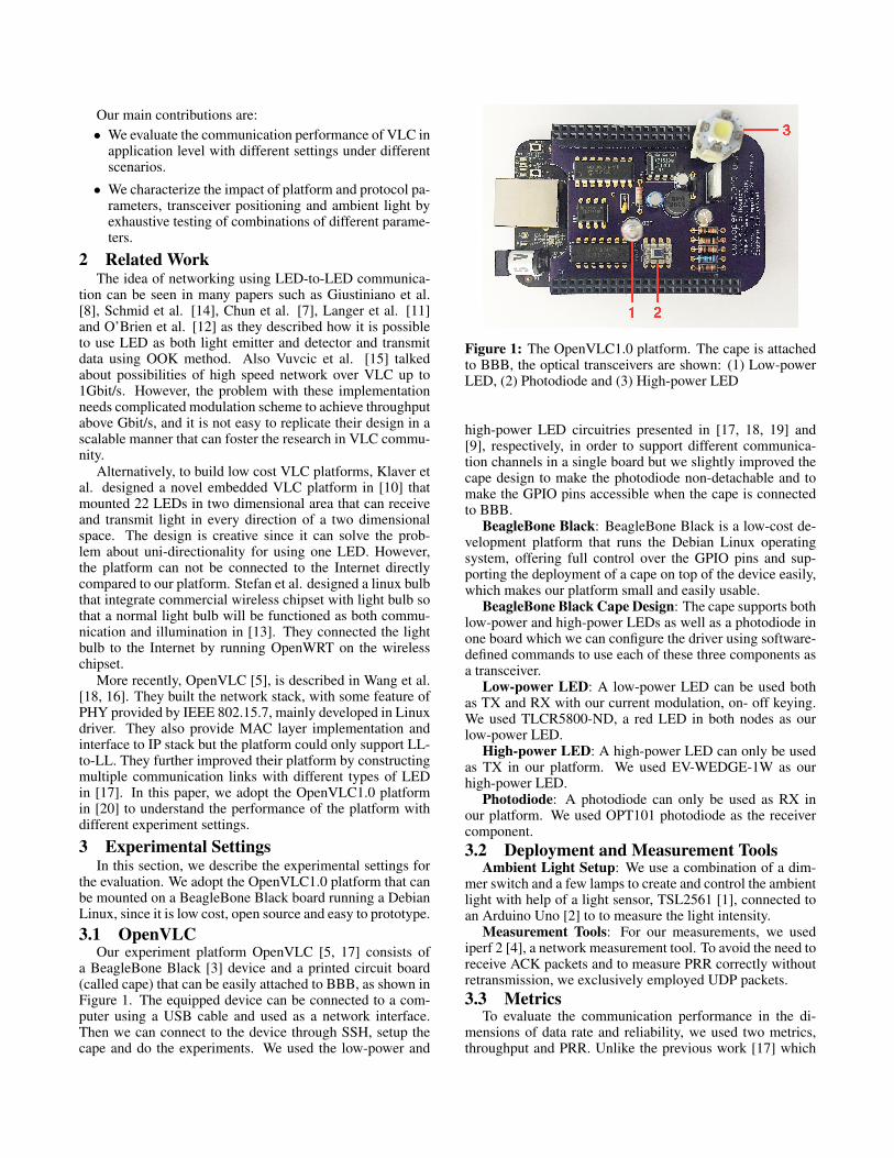
4.3 Ambient LightWe designed a set of experiments to observe the impact
of indoor lighting on the performance of VLC. We conductedthe indoor experiments in a windowless office where ambientlight could be controlled by adjusting the dimming level. Weshow our experiment settings in Table 7. Figure 8 shows theperformance results when we adjust the ambient light levelin typical indoor scenarios. One interesting result can be ob-served in Figure 8a which in a complete dark room (1 lx),the VLC performance is less than the regular office lightingscenario (120 lx). The reason for this behavior is the spectralresponsivity of the receiver component (LL and PD [6]). In acomplete dark room, the red low-power LED we used cannotsaturate the receiver enough to output a considerable amountof voltage. But the white high-power LED can easily satu-rate the receiver as the results in Figure 8b suggest. Whencomparing LL and HL as TX in the dark room, we observethat the VLC performance for HL is better than LL and evenbetter than typical office lighting.
5 ConclusionsWe have investigated the performance of embedded VLC
channels in various scenarios, focusing on the key perfor-mance metrics such as throughput and packet reception ra-tio. After investigating various setups, we have ascertainedthat no single setup can guarantee an adequate performanceacross different scenarios. Going forward, we believe thatembedded VLC efforts should keep all options open. Forinstance, LEDs deserve to be considered as receivers besidephotodiodes and high-power LEDs can be attractive for om-nidirectional communication. The impact of ambient light issignificant, and the use of cheap front-end optics to lessen itshould be considered.
0
2
4
6
8
10
12
14
Data
Rate
(kb
ps)
1 120 300Ambient Light (Lux)
0
20
40
60
80
100
PR
R (
%)
LL to LL
LL to PD
(a) Low-power LED as TX
0
2
4
6
8
10
12
14
Data
Rate
(kb
ps)
1 120 300Ambient Light (Lux)
0
20
40
60
80
100
PR
R (
%)
HL to LL
HL to PD
(b) High-power LED as TX
Figure 8: Impact of ambient light level on data rate andpacket reception ratio. We only show results for 50kHz inthis figure.
1 120 300Ambient Light (Lux)
30
50
60
Frequency
(kH
z)
0
3
6
9
12
15
Data
Rate
(kb
ps)
(a) LL-to-PD
1 120 300Ambient Light (Lux)
30
50
60
Frequency
(kH
z)
0
3
6
9
12
15
Data
Rate
(kb
ps)
(b) HL-to-PD
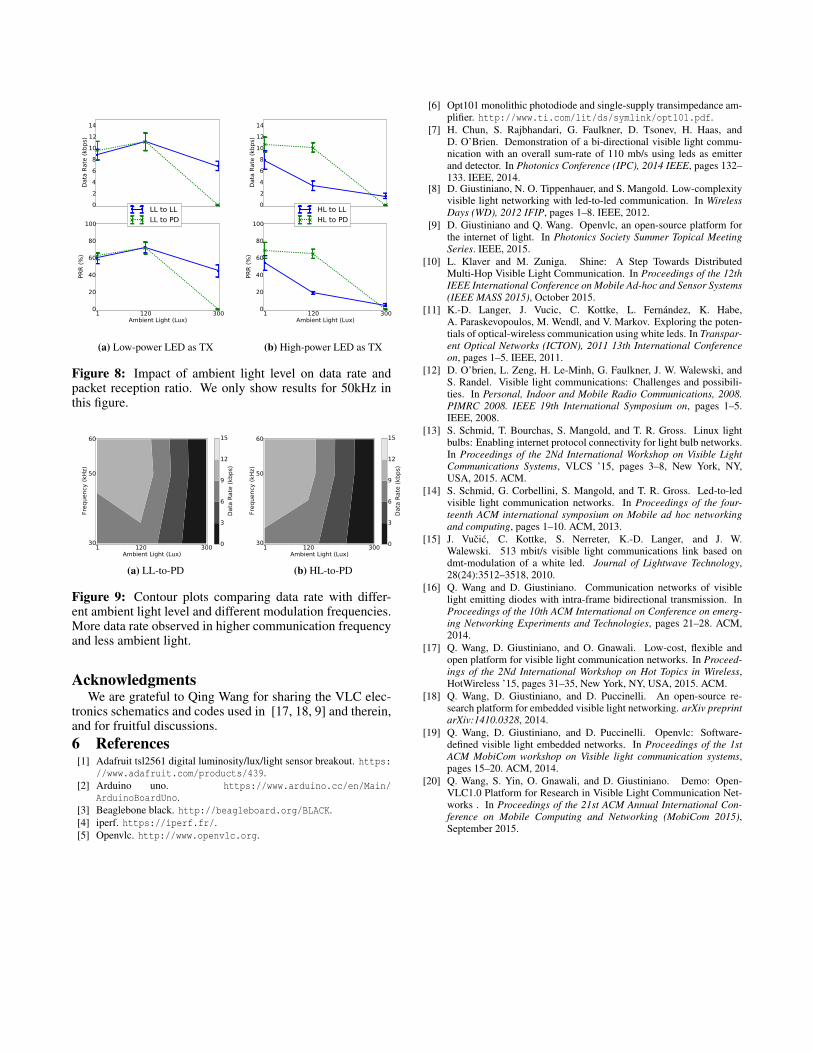
Figure 9: Contour plots comparing data rate with differ-ent ambient light level and different modulation frequencies.More data rate observed in higher communication frequencyand less ambient light.
AcknowledgmentsWe are grateful to Qing Wang for sharing the VLC elec-
tronics schematics and codes used in [17, 18, 9] and therein,and for fruitful discussions.6 References
[1] Adafruit tsl2561 digital luminosity/lux/light sensor breakout. https://www.adafruit.com/products/439.
[2] Arduino uno. https://www.arduino.cc/en/Main/ArduinoBoardUno.
[3] Beaglebone black. http://beagleboard.org/BLACK.[4] iperf. https://iperf.fr/.[5] Openvlc. http://www.openvlc.org.
[6] Opt101 monolithic photodiode and single-supply transimpedance am-plifier. http://www.ti.com/lit/ds/symlink/opt101.pdf.
[7] H. Chun, S. Rajbhandari, G. Faulkner, D. Tsonev, H. Haas, andD. O’Brien. Demonstration of a bi-directional visible light commu-nication with an overall sum-rate of 110 mb/s using leds as emitterand detector. In Photonics Conference (IPC), 2014 IEEE, pages 132–133. IEEE, 2014.
[8] D. Giustiniano, N. O. Tippenhauer, and S. Mangold. Low-complexityvisible light networking with led-to-led communication. In WirelessDays (WD), 2012 IFIP, pages 1–8. IEEE, 2012.
[9] D. Giustiniano and Q. Wang. Openvlc, an open-source platform forthe internet of light. In Photonics Society Summer Topical MeetingSeries. IEEE, 2015.
[10] L. Klaver and M. Zuniga. Shine: A Step Towards DistributedMulti-Hop Visible Light Communication. In Proceedings of the 12thIEEE International Conference on Mobile Ad-hoc and Sensor Systems(IEEE MASS 2015), October 2015.
[11] K.-D. Langer, J. Vucic, C. Kottke, L. Fernandez, K. Habe,A. Paraskevopoulos, M. Wendl, and V. Markov. Exploring the poten-tials of optical-wireless communication using white leds. In Transpar-ent Optical Networks (ICTON), 2011 13th International Conferenceon, pages 1–5. IEEE, 2011.
[12] D. O’brien, L. Zeng, H. Le-Minh, G. Faulkner, J. W. Walewski, andS. Randel. Visible light communications: Challenges and possibili-ties. In Personal, Indoor and Mobile Radio Communications, 2008.PIMRC 2008. IEEE 19th International Symposium on, pages 1–5.IEEE, 2008.
[13] S. Schmid, T. Bourchas, S. Mangold, and T. R. Gross. Linux lightbulbs: Enabling internet protocol connectivity for light bulb networks.In Proceedings of the 2Nd International Workshop on Visible LightCommunications Systems, VLCS ’15, pages 3–8, New York, NY,USA, 2015. ACM.
[14] S. Schmid, G. Corbellini, S. Mangold, and T. R. Gross. Led-to-ledvisible light communication networks. In Proceedings of the four-teenth ACM international symposium on Mobile ad hoc networkingand computing, pages 1–10. ACM, 2013.
[15] J. Vucic, C. Kottke, S. Nerreter, K.-D. Langer, and J. W.Walewski. 513 mbit/s visible light communications link based ondmt-modulation of a white led. Journal of Lightwave Technology,28(24):3512–3518, 2010.
[16] Q. Wang and D. Giustiniano. Communication networks of visiblelight emitting diodes with intra-frame bidirectional transmission. InProceedings of the 10th ACM International on Conference on emerg-ing Networking Experiments and Technologies, pages 21–28. ACM,2014.
[17] Q. Wang, D. Giustiniano, and O. Gnawali. Low-cost, flexible andopen platform for visible light communication networks. In Proceed-ings of the 2Nd International Workshop on Hot Topics in Wireless,HotWireless ’15, pages 31–35, New York, NY, USA, 2015. ACM.
[18] Q. Wang, D. Giustiniano, and D. Puccinelli. An open-source re-search platform for embedded visible light networking. arXiv preprintarXiv:1410.0328, 2014.
[19] Q. Wang, D. Giustiniano, and D. Puccinelli. Openvlc: Software-defined visible light embedded networks. In Proceedings of the 1stACM MobiCom workshop on Visible light communication systems,pages 15–20. ACM, 2014.
[20] Q. Wang, S. Yin, O. Gnawali, and D. Giustiniano. Demo: Open-VLC1.0 Platform for Research in Visible Light Communication Net-works . In Proceedings of the 21st ACM Annual International Con-ference on Mobile Computing and Networking (MobiCom 2015),September 2015.