Embed Size (px)
Citation preview
Electronics and Photonics for High Energy Physics Experiments
Krzysztof T. Pozniak Institute of Electronic Systems, Warsaw University of Technology
Nowowiejska 15/19, 00-665 Warsaw, Poland
ABSTRACT The paper presents a debate over objective conditions connected with high energy physics (hep) experiments. Some consequences stem from these conditions concerning requirements for electronic apparatus and its structure. Systematic characteristics of electronic systems for such experiments were included. The following layers of electronics are distinguished: detector electronics, triggering electronics, data acquisition and supervision-management-diagnostic. Methods to design and fabricate described systems were presented.
Keywords: photonic and electronic systems, front-end electronics, trigger electronics, data acquisition and processing
1. INTRODUCTION Basic aim of High Energy Physics (HEP) experiments is deepening of our knowledge about the structure of matter. This aim is achieved with help of counter-propagating particles colliders. Elementary particles such as electrons or hadrons are accelerated and periodically collided. Complex detection arrangements measure and register results of interactions. They are built in the point of particles’ interactions. Tracks and energies of particles are measured and stored with the help of specialized electronic systems. These systems co-operate with particles detectors such as scintillators or gas chambers. This type of apparatus is usually designed by experts for particular experiment, and possesses unique character. It is not possible to solve such challenging problems using routine engineering methods, because of high degree of task complexity. Special advanced R&D programmes have to be open and their scientific results cause general development of electronics too. Discussion of the requirements imposed on electronic apparatus and their structure in respect to hep experiments demands was presented.
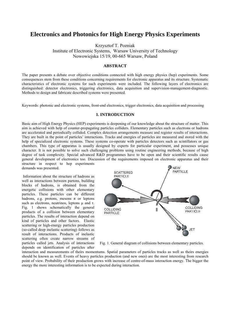
Information about the structure of hadrons as well as interactions between partons, building blocks of hadrons, is obtained from the energetic collisions with other elementary particles. These particles can be different hadrons, e.g. protons, mesons π or leptons such as electrons, neutrinos, leptons µ and τ. Fig. 1 shows schematically the general products of a collision between elementary particles. The results of interaction depend on kind of particles and other factors. Elastic scattering or high-energy particles production (so-called deep inelastic scattering) follows as result of interactions. Products of inelastic scattering often create narrow streams of particles called jets. Analysis of interactions depends on identification of particles after interaction and measurements of theirs momentums. Spatial parameters of particles tracks as well as theirs energies should be known as well. Events of heavy particles production (and new ones) are the most interesting from research point of view. Probability of their production grows with increase of centre-of-mass interaction energy. The bigger the energy the more interesting information is to be expected during interaction.
Fig. 1. General diagram of collisions between elementary particles.
Particle bundles colliders are now the best devices, which permit to get very high centre-of-mass energy and luminosity1. Principle of working of accelerators depends on accelerating of particular particles type and giving them energy in strong electric field. General dependence describing energy is expressed as following: BAEEE 2= , where parameters EA and EB express energies of particles during interaction. This shows that maximization of centre-of-mass energy demands acceleration of both crossing particles. There are two types of accelerators, depending on the way the bunches of particles are accelerated: • linear - bunches are accelerated and
collided along a straight line only a single time (they are dumped after collision). Nominal energy of bunches have to be set during single pass through the accelerator,
• circular - bunches are accelerated and bunches cross each other repeatedly. Nominal energies of bunches are obtained after making many loops in the accelerators.
Two different families of accelerators are defined by character of bunches. There are generally two types of bunches: • continuous – particle interaction can be
set at any moment of time, • packet - particles are formed into special
packets and packets are collided with each other at certain periodicity.
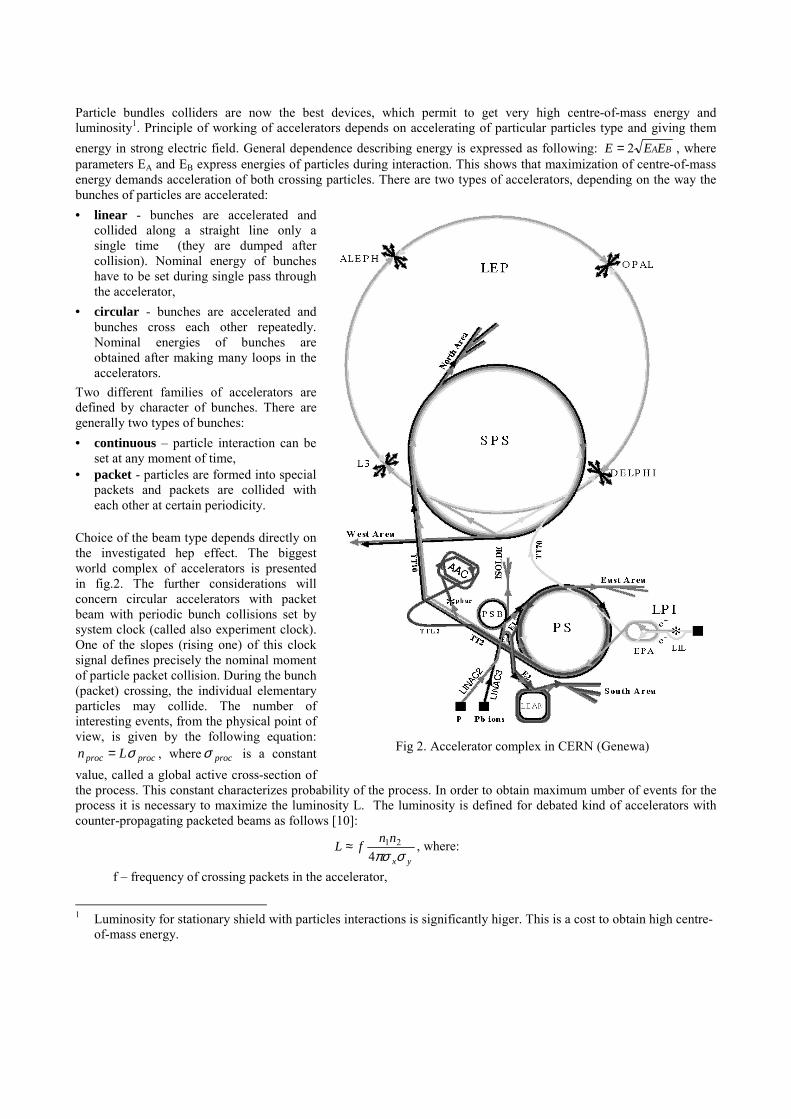
Choice of the beam type depends directly on the investigated hep effect. The biggest world complex of accelerators is presented in fig.2. The further considerations will concern circular accelerators with packet beam with periodic bunch collisions set by system clock (called also experiment clock). One of the slopes (rising one) of this clock signal defines precisely the nominal moment of particle packet collision. During the bunch (packet) crossing, the individual elementary particles may collide. The number of interesting events, from the physical point of view, is given by the following equation:
procproc Ln σ= , where procσ is a constant value, called a global active cross-section of the process. This constant characterizes probability of the process. In order to obtain maximum umber of events for the process it is necessary to maximize the luminosity L. The luminosity is defined for debated kind of accelerators with counter-propagating packeted beams as follows [10]:
yx
nnfLσπσ421≈ , where:
f – frequency of crossing packets in the accelerator,
1 Luminosity for stationary shield with particles interactions is significantly higer. This is a cost to obtain high centre-
of-mass energy.
Fig 2. Accelerator complex in CERN (Genewa)
n1, n2 – numbers of particles included in crossing bunches, σx, σy – particle density dispersions in bunches, expressed by Gauss distribution in the beam cross-section.
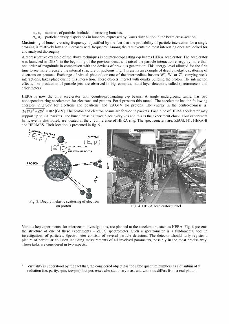
Maximising of bunch crossing frequency is justified by the fact that the probability of particle interaction for a single crossing is relatively low and increases with frequency. Among the rare events the most interesting ones are looked for and analysed thoroughly. A representative example of the above techniques is counter-propagating e-p beams HERA accelerator. The accelerator was launched in DESY in the beginning of the previous decade. It raised the particle interaction energy by more than one order of magnitude in comparison with the devices of previous generation. This energy level allowed for the first time to see more precisely the internal structure of nucleons. Fig. 3 presents an example of deeply inelastic scattering of electrons on protons. Exchange of virtual photon2, or one of the intermediate bosons W+, W- or Z0, carrying weak interactions, takes place during this interaction. These objects interact with quarks building the proton. The interaction effects, like production of particle jets, are observed in big, complex, multi-layer detectors, called spectrometers and calorimeters.
HERA is now the only accelerator with counter-propagating e-p beams. A single underground tunnel has two nondependent ring accelerators for electrons and protons. Fot.4 presents this tunnel. The accelerator has the following energies: 27,8GeV for electrons and positrons, and 820GeV for protons. The energy in the centre-of-mass is:
22 8208.272 + =302 [GeV]. The proton and electron beams are formed in packets. Each pipe of HERA accelerator may support up to 220 packets. The bunch crossing takes place every 96s and this is the experiment clock. Four experiment halls, evenly distributed, are located at the circumference of HERA ring. The spectrometers are: ZEUS, H1, HERA-B and HERMES. Their location is presented in fig. 5.
Various hep experiments, for microcosm investigations, are planned at the accelerators, such as HERA. Fig. 6 presents the structure of one of these experiments – ZEUS spectrometer. Such a spectrometer is a fundamental tool in investigations of particles. Spectrometer consists of several particle detectors. The detector should fully register a picture of particular collision including measurements of all involved parameters, possibly in the most precise way. These tasks are considered in two aspects:
2 Virtuality is understood by the fact that, the considered object has the same quantum numbers as a quantum of γ
radiation (i.e. parity, spin, izospin), but possesses also stationary mass and with this differs from a real photon.
Fig. 3. Deeply inelastic scattering of electron
on proton. Fig. 4. HERA accelerator tunnel.
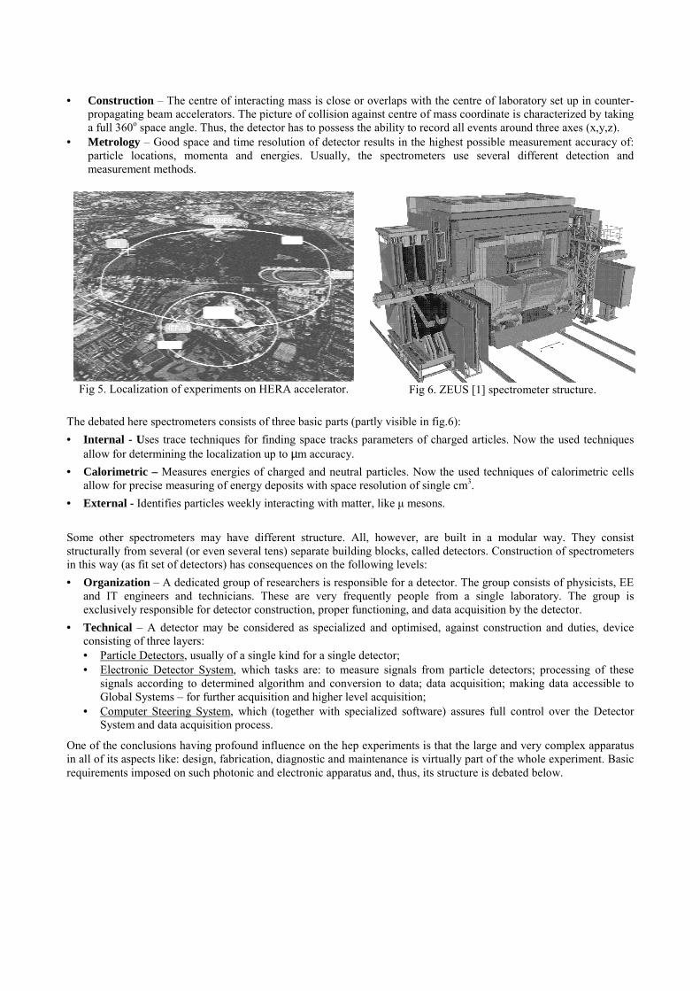
• Construction – The centre of interacting mass is close or overlaps with the centre of laboratory set up in counter-propagating beam accelerators. The picture of collision against centre of mass coordinate is characterized by taking a full 360o space angle. Thus, the detector has to possess the ability to record all events around three axes (x,y,z).
• Metrology – Good space and time resolution of detector results in the highest possible measurement accuracy of: particle locations, momenta and energies. Usually, the spectrometers use several different detection and measurement methods.
The debated here spectrometers consists of three basic parts (partly visible in fig.6): • Internal - Uses trace techniques for finding space tracks parameters of charged articles. Now the used techniques
allow for determining the localization up to µm accuracy. • Calorimetric – Measures energies of charged and neutral particles. Now the used techniques of calorimetric cells
allow for precise measuring of energy deposits with space resolution of single cm3. • External - Identifies particles weekly interacting with matter, like µ mesons. Some other spectrometers may have different structure. All, however, are built in a modular way. They consist structurally from several (or even several tens) separate building blocks, called detectors. Construction of spectrometers in this way (as fit set of detectors) has consequences on the following levels: • Organization – A dedicated group of researchers is responsible for a detector. The group consists of physicists, EE
and IT engineers and technicians. These are very frequently people from a single laboratory. The group is exclusively responsible for detector construction, proper functioning, and data acquisition by the detector.
• Technical – A detector may be considered as specialized and optimised, against construction and duties, device consisting of three layers: • Particle Detectors, usually of a single kind for a single detector; • Electronic Detector System, which tasks are: to measure signals from particle detectors; processing of these
signals according to determined algorithm and conversion to data; data acquisition; making data accessible to Global Systems – for further acquisition and higher level acquisition;
• Computer Steering System, which (together with specialized software) assures full control over the Detector System and data acquisition process.
One of the conclusions having profound influence on the hep experiments is that the large and very complex apparatus in all of its aspects like: design, fabrication, diagnostic and maintenance is virtually part of the whole experiment. Basic requirements imposed on such photonic and electronic apparatus and, thus, its structure is debated below.
Fig 5. Localization of experiments on HERA accelerator. Fig 6. ZEUS [1] spectrometer structure.
2. CHARACTERISTICS OF PHOTONIC AND ELECTRONIC SYSTEMS FOR HEP EXPERIMENTS
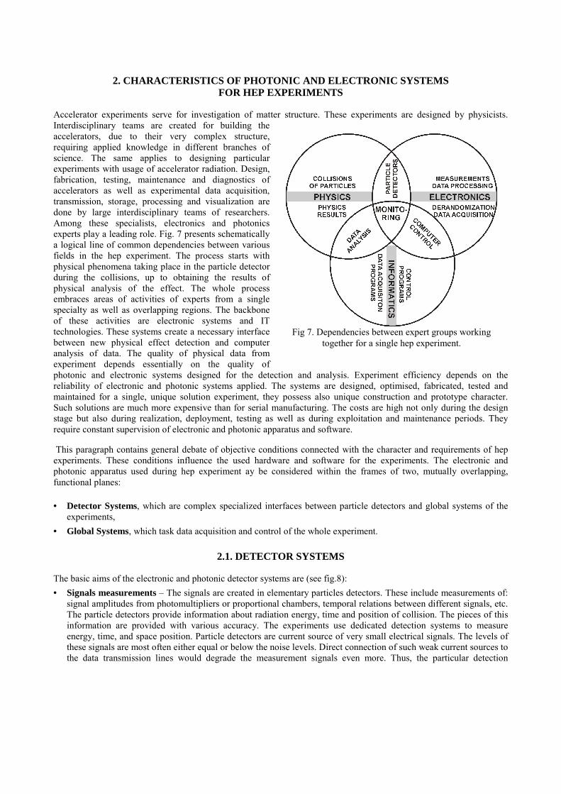
Accelerator experiments serve for investigation of matter structure. These experiments are designed by physicists. Interdisciplinary teams are created for building the accelerators, due to their very complex structure, requiring applied knowledge in different branches of science. The same applies to designing particular experiments with usage of accelerator radiation. Design, fabrication, testing, maintenance and diagnostics of accelerators as well as experimental data acquisition, transmission, storage, processing and visualization are done by large interdisciplinary teams of researchers. Among these specialists, electronics and photonics experts play a leading role. Fig. 7 presents schematically a logical line of common dependencies between various fields in the hep experiment. The process starts with physical phenomena taking place in the particle detector during the collisions, up to obtaining the results of physical analysis of the effect. The whole process embraces areas of activities of experts from a single specialty as well as overlapping regions. The backbone of these activities are electronic systems and IT technologies. These systems create a necessary interface between new physical effect detection and computer analysis of data. The quality of physical data from experiment depends essentially on the quality of photonic and electronic systems designed for the detection and analysis. Experiment efficiency depends on the reliability of electronic and photonic systems applied. The systems are designed, optimised, fabricated, tested and maintained for a single, unique solution experiment, they possess also unique construction and prototype character. Such solutions are much more expensive than for serial manufacturing. The costs are high not only during the design stage but also during realization, deployment, testing as well as during exploitation and maintenance periods. They require constant supervision of electronic and photonic apparatus and software.
This paragraph contains general debate of objective conditions connected with the character and requirements of hep experiments. These conditions influence the used hardware and software for the experiments. The electronic and photonic apparatus used during hep experiment ay be considered within the frames of two, mutually overlapping, functional planes:
• Detector Systems, which are complex specialized interfaces between particle detectors and global systems of the experiments,
• Global Systems, which task data acquisition and control of the whole experiment.
2.1. DETECTOR SYSTEMS The basic aims of the electronic and photonic detector systems are (see fig.8): • Signals measurements – The signals are created in elementary particles detectors. These include measurements of:
signal amplitudes from photomultipliers or proportional chambers, temporal relations between different signals, etc. The particle detectors provide information about radiation energy, time and position of collision. The pieces of this information are provided with various accuracy. The experiments use dedicated detection systems to measure energy, time, and space position. Particle detectors are current source of very small electrical signals. The levels of these signals are most often either equal or below the noise levels. Direct connection of such weak current sources to the data transmission lines would degrade the measurement signals even more. Thus, the particular detection
Fig 7. Dependencies between expert groups working together for a single hep experiment.
systems require special measurement electronics located very closely to the particle detector3. Most frequently, the measurement process leads to signal transformation to digital form via AD conversion. Either the directly measured signals are transformed or their derivatives. These derivatives are formed in such circuits as shaping ones, discriminators, etc. The resulting data are sent with the rate equal to the system clock or its multiplication.
• Signal processing – It is done in order to obtain valid values of physical data, like: analysis of signals obtained from particle detectors in order to extract particle path [7] etc. The main aim of signal processing in hep experiments is data conversion from a form delivered by measurement circuits to a form acceptable by acquisition sub-systems. Certain characteristic stages of processing can be distinguished: • Synchronization – The aim is to provide teporal correlation between the moment of physical event detection up
to the moment of data acquisition. The same event recorded in all available detectors has to be clearly distinguished. All descriptions have to lead to a single, common, full event picture. Synchronization is provided by the system experiment clock. The experiment measures time in these quanta.
• Compression and multiplexing – Data are initially processed to reduce the number of transmission lines/channels or/and interconnections between them. The detectors are heavily segmented. Each bunch crossing generates response in a very confined number of these segments, say below 1% of detection components and transmission channels. These features allow for implementation such algorithms as “zeros compression” [3] or „partition compression” [4]. Each of these algorithms has to be synchronous.
• Functional processing – It is understood as a series of dedicated processes realizaing assumed function of the detector. Such a function is determination of particle path [5], calculation of energy deposit, etc. It is the most important kind of data processing, from the point of view of the experiment. The experiment trigger is obtained from these necessary data.
• Data acquisition – The most important aim of data acquisition is data registration and recording. The process should contain all necessary information allowing for full off-line numerical event analysis with energies, time, space and eventually full picture reconstruction. Data, which are subject to acquisition are: digital information about the fact of particle detection in the scintillator, topological data like particle passages, energy data like energy deposits. Auxiliary data are also subject to acquisition: frequency of interactions, distribution of values, etc. Trying to generalize, the structure of acquisition circuits can be presented in the following blocks: • Delay line - The flowing stream of data awaits for decision from the experiment Global Triggering System. The
length of delay line (or value of delay time) stems from period of time necessary to calculate the triggering decision and transmission of this signal to all data acquisition sub-systems. Data not chosen by the trigger are irretrievably lost
• Derandomizer – The task of this functional device is minimization of necessary throughput of signal transmission channels. The device buffers the incoming statistical signals and sending them out synchronously with the system clock or with the maximum allowable channel rate. The buffer has to possess appropriate depth/capacity.
• Data buffer – Triggered data are stored and made accessible for further processing in the data buffer. The technical solutions met at this stage of signal processing assure access to stored data for the computer systems. Since this moment, further data processing is done in standard computer environment.
Despite profound functional differences, the combinations between processing and acquisition processes are so close and strong in the contemporary hep experiments that they have to be considered together. The basic properties of both of these sub-systems are very close. They can be considered as fast, multichannel, synchronous, distributed and pipelined electronic and photonic systems (measurment, acquisitin and control), where these attributes are described as follows: • speed stems primarily from big frequency of bunch crossing imposed by the accelerator. The Detector System has to
be ready for nondependent performance of particular stages of signal analysis for each successive, registered image of colliding particle packets.
• Multichannel functionality is combined with the necessity to provide sufficiently big space resolution in the detector for the measurements of energy deposits, particle paths after collisions; A lot of data created in the events requires big number of measurement channels.
3 Electronics placed very closely to or directly on the particle detectors is called commonly „front-end-electronics”
• Synchronism functionality is referenced against successive bunch crossings. It allows to preserve time correlation with the real event time at all stages of data processing in all data channels in particular Detector System. The absolute time is also kept in reference to the Experiment Global Data Acquisition System.
• Distribution functionality is combined with big geometrical dimensionsof the spectrometers. The distances within are considerable. There is no place within the device to install electronic and photonic apparatus. There is a considerable level of ionising radiation inside the spectrometer, especially close to the interaction point. The distances may be even of the order of several tens of m. .
• Pipeline bus character functionality stems indirectly from the required speed and synchronism of the system. It allows for signal processing by successive functional blocks. This leads to increase in efficiency of the Detector Systems.
2.2. GLOBAL SYSTEMS
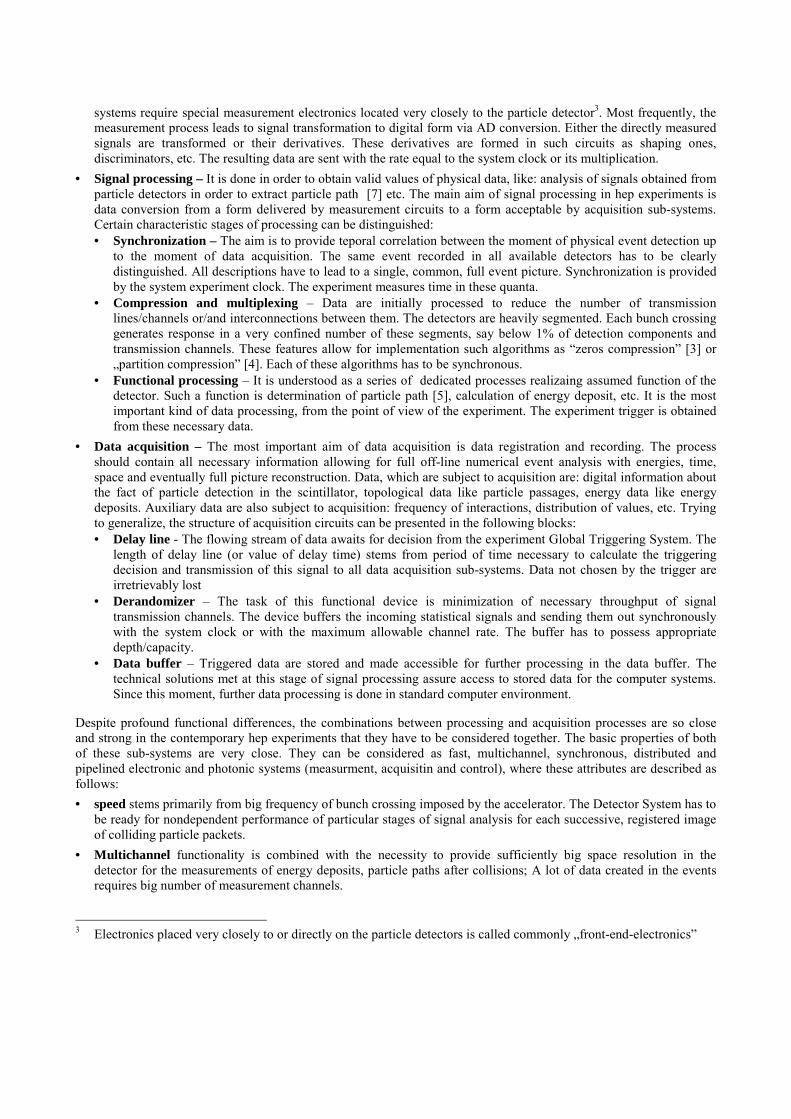
Particular Detector Systems provide information to Global Systems of the experiment and are directly under their control. The Global Systems may be divided, according to their functionalities, to the following main layers (see fig.8): • Global Triggering System – GTS chooses
interesting cases from the physical point of view. Only data concerning these chosen cases are eventually remembered by the Detector Systems. All other cases are irreversibly deleted and lost. This data loss procedure stems form the fact that the probability of interesting collisions is very low indeed. The events of very low active cross section are looked for. Large frequency of bunch crossing gives a lot of unnecessary data. Recording and analysis of all this data would be very expensive, if not possible at all for practical realisation. Therefore, the current hep system solutions are provided with Global Triggering System. GTS decides which, initially registered data, and processed by Detector Systems have to be stored permanently. GTS and Detector Systems have unique functionality, because they are designed only for particular experiment and never are repeated. This unique character concerns type of effects to be measured and is combined with spectrometer structure. DS collects data from detectors. The structure of GTS is usually multistage. The eventual choice of the most interesting cases is done in the last trigger level, after a few layers of signal processing. The commonly met solutions combine First Level of Trigger with the Data Processing and Acquisition Systems [1]. Next levels are combined with computer based data processing systems.
• Global Data Acquisition System is collecting data chosen by the GST and provided by the Detector Systems. The aim of this system is to enable the whole event reconstruction. This requires collection of all relevant data concerning this case from all Detector Systems. Then, such data are recorded on a permanent storage medium. The GTS is responsible for the choice of interesting cases according to preset elimination procedures. The triggering is multilevel. At least one of the selection processes for interesting cases is realized on the level of GDAS. GDAS is built now by fast computer farms working in real time. The computers in farm are connected by very fast gigabit network and links.
Fig. 8. Example of System solution in experiment.
• Global System of Experiment Management – The task of GSEM is continuous, uninterrupted supervision of the experiment hardware state and quality of obtained data. GSEM fulfils very important supporting and centralising roles. GSEM does the following main tasks: • Experiment management – This task relies on: setting of work parameters of the experient; management of the
registration process of the collisions, according to preset physical conditions; determining of hardware tests; • Experiment supervision - All important parameters of each detector are under constant monitoring. These
parameters are: voltages, supply currents, hardware work temperatures, concentration and pressures of gases used in chambers. The global parameters of experiments are also monitored like: atmospheric pressure, humidity, temperatures, ionizing radiation doses, etc. Many other sub-systems and devices, especially electronic and photonic ones, are also monitored by GSEM. Their expected nominal work conditions are traced.
The ways of supervision by GSEM may be arranged, from the functional point of view, in three major groups: • Hardware tests – embrace all nondependent test groups for electronics and photonics. For example, the
Detector System is tested with the aid of special sets of simulating signals. • Parameters monitoring – Nominal work parameters of electronic and photonic hardware are constantly
monitored. For example, this monitoring concerns, among others: values of high voltage supply of photomultipliers, supply currents from the power units of low voltage.
• Quality control – QC bases on signal tests. It allows, with the aid of specially signed, real data signal sequences or prepared testing codes, controlling of data processing during the whole complex process of obtaining physical data from the raw measurement data.
2.3. TECHNOLOGICAL AND CONSTRUCTION ASPECTS The tough requirements for electronics and photonics applied in hep experiments concern practically all devices including ultra fast analogue circuits and converters, up to highly integrated electronic matrices and photonic hybrid ICs. The requirements, including such factors as reliability and maintainability, are comparable to the ones necessary for deep space applications. The design process of such hep systems requires thorough consideration of the following problems: • Necessity to use the newest technologies, this concerns the newest commercial ands research solutions of hardware
and software design tools to fulfill the ultimate design parameters imposed by successive generations of hep experiments;
• Lasting usually more than a decade and multistage period of design work and the necessity of close cooperation between the experts of various (sometimes distant) branches of science and technology;
• Capability of electronic and photonic systems to versatile diagnostics during the permenent long lasting work in the experiment. Unique soltions are used preventing previous experience. These systems are working in adverse environments like: ionizing radiation, elevated temperatures, EMI.
Because of the hep experiment system complexity, the palette of applied technological solutions may be quite broad. Let us mention here only a few chosen, characteristic and frequently applied practically technologies: • Programmable and specialized ICs are very characteristic application in the development of electronic and
photonic circuits not only for hep hardware. The usage of ASICs and programmable ICs like Xilinx and Altera is now common. There are several reasons why these ICs are the only reasonable solution: • Big packing density forces usage of multichannel circus able to co-operate with multichannel devices like:
silicon pixel detectors, strip silicon detectors, drift silicon detectors and multichannel electronic and photonic processing boards – placed in crates outside the spectrometer [8,9],
• Specific technical requirements concerning analog parameters (noise, speed, architecture, which are not standard parameters of deviced met in the off-shelf devices offered in catalogues), also digital parameters (dedicated processing algorithms, big number of different signals, possibility to introduce modifications in programmable circuits),
• Strict confinements on level of consumed power stem from both, difficulties in providing high power to the distance of a few tens of meters inside the spectrometer and dissipation of large amount of heat from inside of active volume of spectrometer.
• Strong fields of ionising radiation in which all front-end electronics and photonics has to work for very long time with high reliability. The usage of radiation-hardened components is recommended in hep experiments hardware, which works close to the radiation sources.
Three different technological solutions are used depending on degree of detection system segmentation and extent of single detection components: • Specialized ICs applied for readout from position detectors. Position detectors are characterized by a very large
number of individual silicon detecting components. The relevant number is a few millions for silicon detectors for such experiments as ATLAS and CMS. The same number of electronic and/or photonic channels of front-end circuits is required.
• Hybrid circuits are built with the usage of off-the-shelf components as well as specialized ICs. • Circuits build on multilayer PCBs use also all available up-to-the-date technologies and components, off-the-
shelf and specialized ICs. • Optoelectronic circuits, devices and sub-systems are more and more frequently used in hep experiments. Some of
these solutions offer competitive work parameters but are sometimes still quite expensive. They work in domain of very fast signal transmission and may in some applications be uncompromised [6]. For example, the CMS experiment uses 100 millions channels and the system clock works with 40MHz. The amount of data is tremendous. Work is carried not only on digital but also analogue transmission of optical data. Analog, very fast optical links are promising because, in some cases, no digital preprocessing of data is necessary.
There are, however, some difficult and characteristic features of work carried on the hardware for hep experiments. These are: • Very long time of system realization, nearing now to a decade. Such a long period is caused by dimensions, large
number of components and sub-systems, complexity level of designed electronic and photonic systems and necessity to synchronize the design, testing and fabrication efforts with other large sub-systems like other detectors, Global Experiment Management System, etc.
• High costs of system realisation, now counted in billions of $. They stem from the large scale of contemporary hep experiments. These experiments are big. Employ structurally very complex electronic and photonic systems, the newest hardware, software and design technologies.
• Irreversibility of system realization stages, which stem from very long time of design, test manufacturing, testing, and fabrication. A unique, single usage solution is a result of this process. The system is designed many years before it is actually used. The eventual estimation of systems parameters and usability is done during the real hep experiment. It is impossible then to make more serious corrections inside the system.
3. CONCLUSIONS The fast evolution of electronic and photonic systems used in hep experiments is stimulated by new demanding research aims in the area of new elementary particle detection. New, large generations of experiments are now under construction like: H1, ZEUS, CMS, ATLAS and other ones. Constant increase in demands is observed like: accuracy, stability, reliability, durability, radiation hardness, speed of measurements, processing and data registration, geometrical extent – bigger number of channels, bigger dimensions of spectrometers, etc. The experiments are a single time build objects and possess unique character. In this respect these systems are difficult for design and especially avoid any kind of standardization. The newest solutions have to be applied during the design process of these systems. These solutions have to be reliable for many years to come of experiment life. The experiment designers have to look for new solutions, unique for the realisation of the research aim. The new solutions are looked for in: design methods, processing algorithms, reliability, radiation hardness, etc. The activity in the field of hep experiments is a powerful engine of electronics and photonics development. Long lasting process of hep system design, testing and exploitation in demanding conditions is a kind of powerful testing environment for all methods, technologies and involved people.
4. REFERENCES 1. ZEUS Collaboration, The ZEUS Detector Status Report, 1993, p.11-1
2. K.Poźniak, I Kudla, R. Kupczak, GFLT signal testing and distribution within the BAC system, ZEUS-Note 96-116 3. K. Poźniak, „Software control and testing of the HIT-READOUT for the BAC detector”, ZEUS-Note 96-117, 1996 4. M. Gorski, I.M. Kudła, K.T. Poźniak: Resistive Plate Chamber (RPC) based muon trigger system for the CMS
experiment – data compression/decompression system, Nucl. Instr. and Meth. in Phys. Res A 419, pp. 701-706, 1998
5. Z. Jaworski, I.M. Kudła, W. Kuzmicz, M. Niewczas, Resistive Plate Chamber (RPC) based muon trigger system for the CMS experiment – pattern comparator ASIC, Nucl. Instr. and Meth. in Phys. Res A 419, pp. 707-710, 1998
6. Poźniak K., Romaniuk R., Dybko A., „Model of fibre optic , multinode telemetric network cooperating with photonic sensors on the basis of network standard transmission”, Proceedings of SPIE (The International Society for Optical Engineering), Tom 35OF, Bellingham, WA, USA,1998
7. M.Adamus, K.Poźniak: “Photonic Programmable Pulser for Veto Wall Detector, Measuring System Tests in ZEUS Experiment at HERA Accelerator”, Proceedings of SPIE (The International Society for Optical Engineering), Tom 35OF, Bellingham, WA, USA,1998 pp. 303-316.
8. E. Chesi, A. Clark, V. Cindro, W. Dabrowski, D. Ferrere, G. Kramberger, J. Kaplon, C. Lacasta, J. Lozano, M. Mikuz, C. Morone, S. Roe, A. Rugde, R. Szczygiel, A. Tadel, P. Weilhammer, A. Zsenei: Performance of a 128 channel analogue front-end chip for readout of Si strip detector modules for LHC experiment, IEEE Trans. on Nuclear Science, vol.47, no.4, pt.1, Aug. 2000, pp.1434 -1441.
9. A. Rivetti, G. Anelli, F. Anghinolfi, G. Maza, P. Jarron: A Mixed-Signal ASIC for the Silicon Drift Detectors of the ALICE Experiment, Proc. of the 6th Workshop on Electronics for LHC Experiments, Cracow, Poland, 11-15 September 2000, CERN/LHCC/2000-41, pp 142-146.
10. XXVI International Conference on High Energy Physics, 1992, Texas, USA