Embed Size (px)
Citation preview
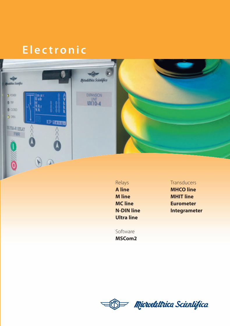
RelaysA lineM lineMC lineN-DIN lineUltra line
SoftwareMSCom2
TransducersMHCO lineMHIT lineEurometerIntegrameter
E l e c t ro n i c
ELT_Brochure_ok.qxd:Layout 1 25-09-2009 14:07 Pagina 1

2
Microelettrica Scientifica Electronic
Division is one of the world
leading companies in the design
and production of Protection
Relays and High Voltage
Transducers for Rail, Substation,
Energy and Industrial application.
The MS Electronic division offers
5 families of analog and digital
protection relays and a variety
of high voltage transducers and
metering devices that can be
personalized in most detail.
A very fast customization process
is at the core of our competencies
and allows us to serve those
customers who require best in
class, but tailored solutions in very
quick times. As all MS divisions,
its quality is in compliance with
standards ISO 9001: 2008 and
ISO 14000. The MS Electronic
division is located in the Rozzano
MS Headquarter, approximately
10 km South of Milan along
the route to Genova.
The Microelettrica Scientifica
Electronic experience and
tradition begins in the 1980’s as
the company develops its first
microprocessor based Protection
Relays, that have constantly
evolved into new lines and types.
On board tranducers and electronic
meters, based on the international
patent of the eurometer have been
added from the mid 1990’s, while
transducers for DC traction
Applications
Rail on Board
DC Substation
Energy
Industry
ELT_Brochure_ok.qxd:Layout 1 25-09-2009 14:07 Pagina 2
3
substations came in the early
2000’s. On board meters were
previously hosted in the separate
company Microdigit located
in Lodi, but have been merged
and fully integrated in the
Microelettrica Scientifica
electronic division in Rozzano
since 2008. As of 2005
Microelettrica Scientifica is
member of the Knorr Bremse
Group, the German world leader
in rail and commercial vehicles
braking systems. Knorr Bremse
Group portfolio for Rail Vehicles
also includes doors and entrance
systems and HVAC systems
for vehicles, as well as platform
screen doors and gates for
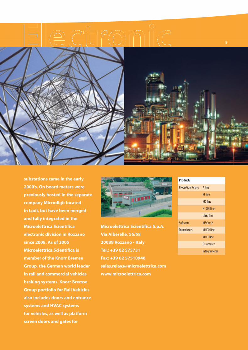
Microelettrica Scientifica S.p.A.
Via Alberelle, 56/58
20089 Rozzano - Italy
Tel.: +39 02 575731
Fax: +39 02 57510940
www.microelettrica.com
Products
Protection Relays A line
M line
MC line
N-DIN line
Software MSCom2
Ultra line
Transducers MHCO line
Eurometer
MHIT line
Integrameter
ELT_Brochure_ok.qxd:Layout 1 25-09-2009 14:07 Pagina 3
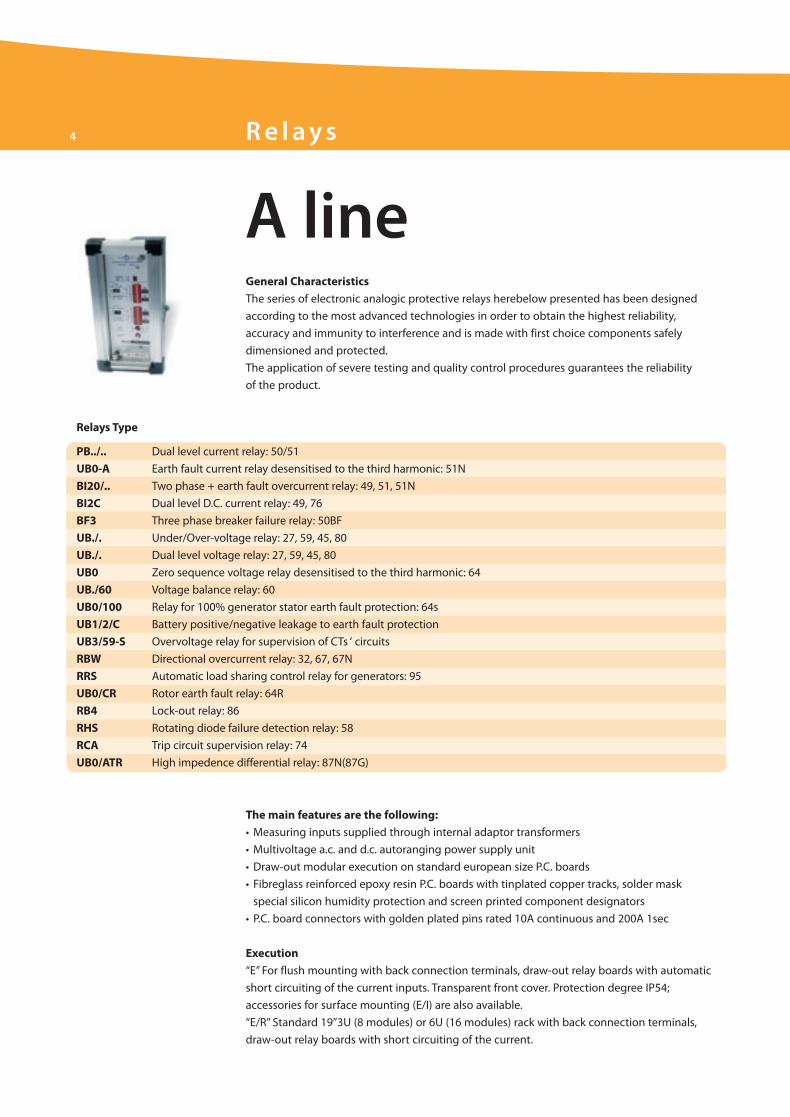
4 R e l ays
A line
PB../.. Dual level current relay: 50/51
UB0-A Earth fault current relay desensitised to the third harmonic: 51N
BI20/.. Two phase + earth fault overcurrent relay: 49, 51, 51N
BI2C Dual level D.C. current relay: 49, 76
BF3 Three phase breaker failure relay: 50BF
UB./. Under/Over-voltage relay: 27, 59, 45, 80
UB./. Dual level voltage relay: 27, 59, 45, 80
UB0 Zero sequence voltage relay desensitised to the third harmonic: 64
UB./60 Voltage balance relay: 60
UB0/100 Relay for 100% generator stator earth fault protection: 64s
UB1/2/C Battery positive/negative leakage to earth fault protection
UB3/59-S Overvoltage relay for supervision of CTs ‘ circuits
RBW Directional overcurrent relay: 32, 67, 67N
RRS Automatic load sharing control relay for generators: 95
UB0/CR Rotor earth fault relay: 64R
RB4 Lock-out relay: 86
RHS Rotating diode failure detection relay: 58
RCA Trip circuit supervision relay: 74
UB0/ATR High impedence differential relay: 87N(87G)
Relays Type
The main features are the following:
• Measuring inputs supplied through internal adaptor transformers
• Multivoltage a.c. and d.c. autoranging power supply unit
• Draw-out modular execution on standard european size P.C. boards
• Fibreglass reinforced epoxy resin P.C. boards with tinplated copper tracks, solder mask
special silicon humidity protection and screen printed component designators
• P.C. board connectors with golden plated pins rated 10A continuous and 200A 1sec
Execution
“E” For flush mounting with back connection terminals, draw-out relay boards with automatic
short circuiting of the current inputs. Transparent front cover. Protection degree IP54;
accessories for surface mounting (E/I) are also available.
“E/R” Standard 19”3U (8 modules) or 6U (16 modules) rack with back connection terminals,
draw-out relay boards with short circuiting of the current.
General Characteristics
The series of electronic analogic protective relays herebelow presented has been designed
according to the most advanced technologies in order to obtain the highest reliability,
accuracy and immunity to interference and is made with first choice components safely
dimensioned and protected.
The application of severe testing and quality control procedures guarantees the reliability
of the product.
ELT_Brochure_ok.qxd:Layout 1 25-09-2009 14:07 Pagina 4
5
Output Relays
Two versions are provided:
• Standard version: the output relays are deenergized on normal operating conditions and are energized on relay’s tripping
• Positive protected version (on request): the output relays are energized on normal operating conditions, (i.e. with auxiliary
supply on and input values at normal levels) and are deenergized on relay ‘s tripping, failure of power supply, internal relay fault
Signalization
• Green led: auxiliary power supply presence
• Red led: trip indication
• Yellow led: trip memorisation
Control
• Relay test with or without tripping of output contacts
• Automatic and/or local/remote reset of the output relays
• Local manual reset only for signal leds
Blocking and Intertripping Circuits
On request are available:
• Blocking input (BI)
• Blocking output (BO)
• Time start output (TO)
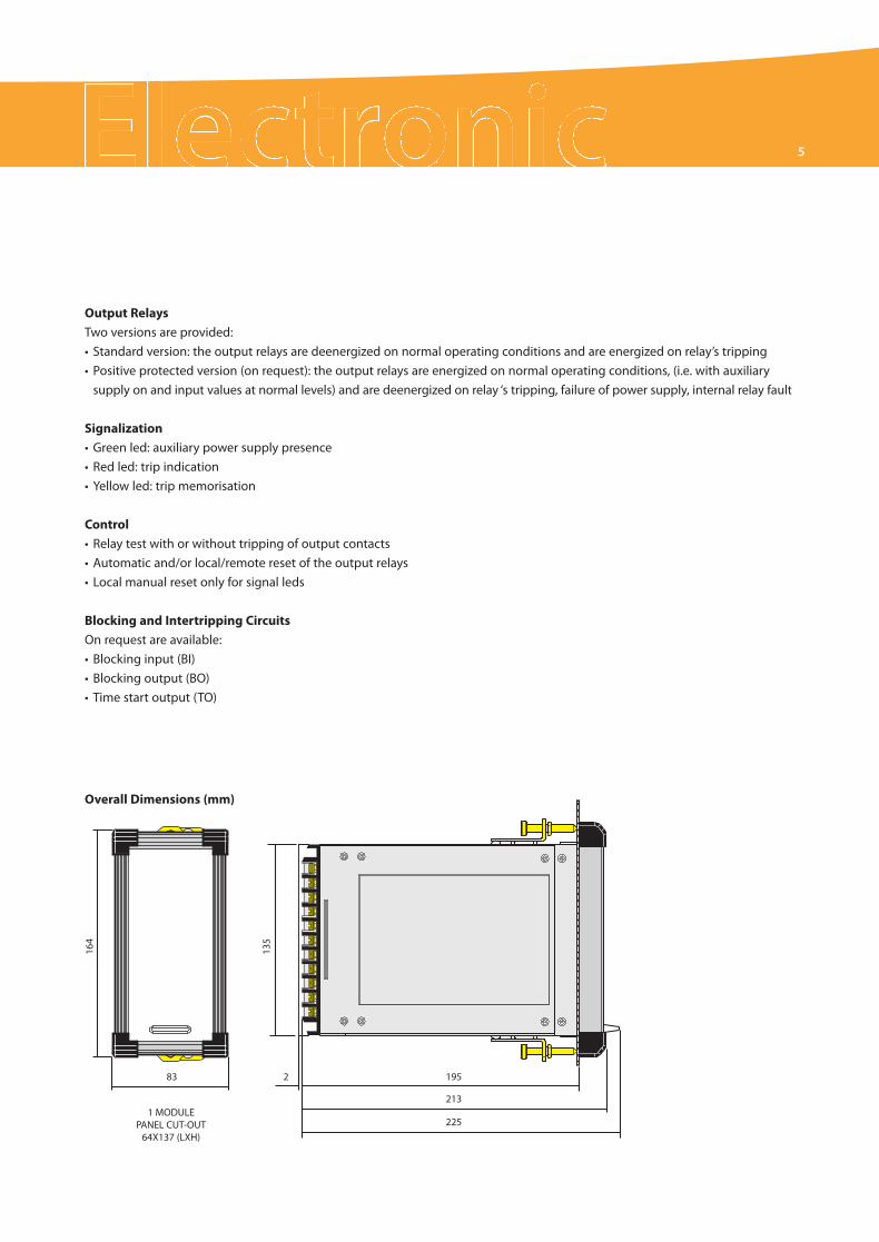
164
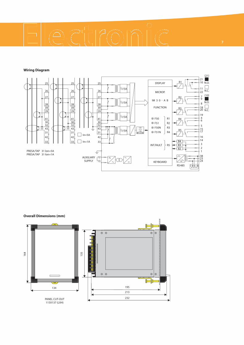
135
83
1 MODULEPANEL CUT-OUT64X137 (LXH)
2 195
213
225
Overall Dimensions (mm)
ELT_Brochure_ok.qxd:Layout 1 25-09-2009 14:07 Pagina 5

M line
Measurements• Real Time Measurements• Maximum Demand and Inrush Recording• Trip Recording (last 5 trips with date & time)
Control• 5 Output Relays (programmable)• 3 Digital Inputs• Time tagged event recording• Blocking Outputs and Blocking Inputfor pilot wire selectivity coordination
Communications• 1 RS485 Serial communication port on rear side• Modbus RTU Communication Protocols
Technical Characteristics• Complete autodiagnostic program• 8 Digit alphanumerical Display• 8 Leds for signalization
Mounting• 2 Module boxes• IP44 protection case (on request IP54)• Totally draw-out execution
Software• MSCom Program interface for devicemanagement
IM30-AB Three-phase Overcurrent and Earth Fault - Dual Setting : 50/51, 50N/51N, 51BF
IM30-AP Three-phase Overcurrent and Earth Fault: 50/51, 50N/51N, 51BF
IM30-C Capacitor Overload, Earth Fault And Unbalance Protection: 50/51, 50N/51N, 46N, 37, 51BF
IM30-D Three-phase Overcurrent + Directional Earth Fault: 50/51, 50N/51N/67N, 59Uo, I2t, 51BF
M-ARM513 Multishot Programmable Single/Three Phase Autoreclose: 79
SCM21 Three Inputs Synchrocheck: 25, 27/59, 81.
MM30 Motor Protection: 12/14, 37, 46, 47, 48, 49, 50/51, 51LR, 64, 66
MM30-D Motor ProtectionWith Directional Earth Fault: 12/14, 37, 46, 47, 48, 49, 50/51, 51LR, 64N, 66
MM30-W Motor Protection RelayWith Voltage & Power Control: 12/14, 27/59, 37, 46, 47, 48, 49, 50/51, 51LR, 55, 64, 66, 81
IM30-T Three-phase Thermal + Overcurrent + Earth Fault: 46, 49, 50/51, 50N/51N, 51BF, I2t
MD32-T Percentage Biased Transformer Differential: 87, 87N
MD33-T Percentage Biased Differential Relay For 3-winding Transformers: 87, 50/51
MTR33 Transformer On-load Tap-Changer Control: 27, 59, 37, 50/51, 90
IM30-G Multifunction Generator Protection: 32, 40, 46, 50/51, 51BF, 64S
IM30-B00 Earth Fault Relay - Dual Setting: 50N/51N, 51BF
IM30-DR Three-phase Overcurrent with Directional Earth Fault + Autoreclosing: 50/51, 50N/51N/67N, 46, 79, 51BF
MG30 Generator Protection & Management: 21, 24, 27/59, 32, 37, 40, 46, 49, 50/27, 50V/51V, 51BF, 60FL, 64S, 81
MD32-G Percentage Biased Generator Differential Relay: 50/51, 87N or 64S, F87, 51BF
SPM21 Generator Synchronizing Relay: 25, 27/59/81, 90
M-LIB3 Modular Low-Impedance Bus-bar Protection: 87B
M-HIB3 High Impedance Biased Differential Relay: 87, 51BF
M-HIV3 Three Phase High Impedance Busbar Differential RelayWith Supervision of CT Secondary Circuits: 87B, 59S
MFP Pilot Wire Differential Protection Relay for Cables & Lines: 87/85, 50/51, 51BF
UM30-A Three-phase Voltage, Frequency & Zero Sequence Voltage with Vector Shift Detection: 24, 27d/59d, 47, 59, 59Uo, 81
UFD34 Three-phase Digital 4-stage Frequency RelayWith Df/dt & Dv/dt Control: 27/59, 81, df/dt, dv/dt
MU30 Multifunction Three-phase Measuring Unit
MW33 Power Management Relay: 27/59, 81, 32
MX7-5 Programmable Interface & Control Module: 7 Digital Inputs & 5 Output Relays
MX14-5 Programmable Interface & Control Module: 14 Digital Inputs & 5 Output Relays
Relays Type
6 R e l ays
General CharacteristicsM line is a complete series of microprocessor based relays suitable for protection of highand medium voltage systems; it offers a unique combination of performances, functionalities,innovation and reliability. The line is completed by a number of communication and controlmodules giving a good level of modularity.
ELT_Brochure_ok.qxd:Layout 1 25-09-2009 14:07 Pagina 6
164
135
134 195
213
232PANEL CUT-OUT115X137 (LXH)
}
PRESA/TAP 31 lon=5APRESA/TAP 31 lon=1A
AUXILIARYSUPPLY
25
26
27
283929
4130324331
42
33
25
26
27
283929
4130324331
42
33
25
26
27
283929
4130324331
42
33
2110
1122
79
81820
1946
51517
1614321
382324
In=5A
In=1A
1213
1/5A
DISPLAY
MICROP.
IM 3 0 - A B
FUNCTION
KEYBOARD
INT.FAULT R5
R1
R2
R3
R4
R5
B4B3B2
RS485
(21)
(10)
N.O.
N.C.
N.O.
N.C.
F50 R1
F51 R2
F50N R3
F51N R4
1/5A
1/5A
1/5A
Wiring Diagram
Overall Dimensions (mm)
7
ELT_Brochure_ok.qxd:Layout 1 25-09-2009 14:07 Pagina 7
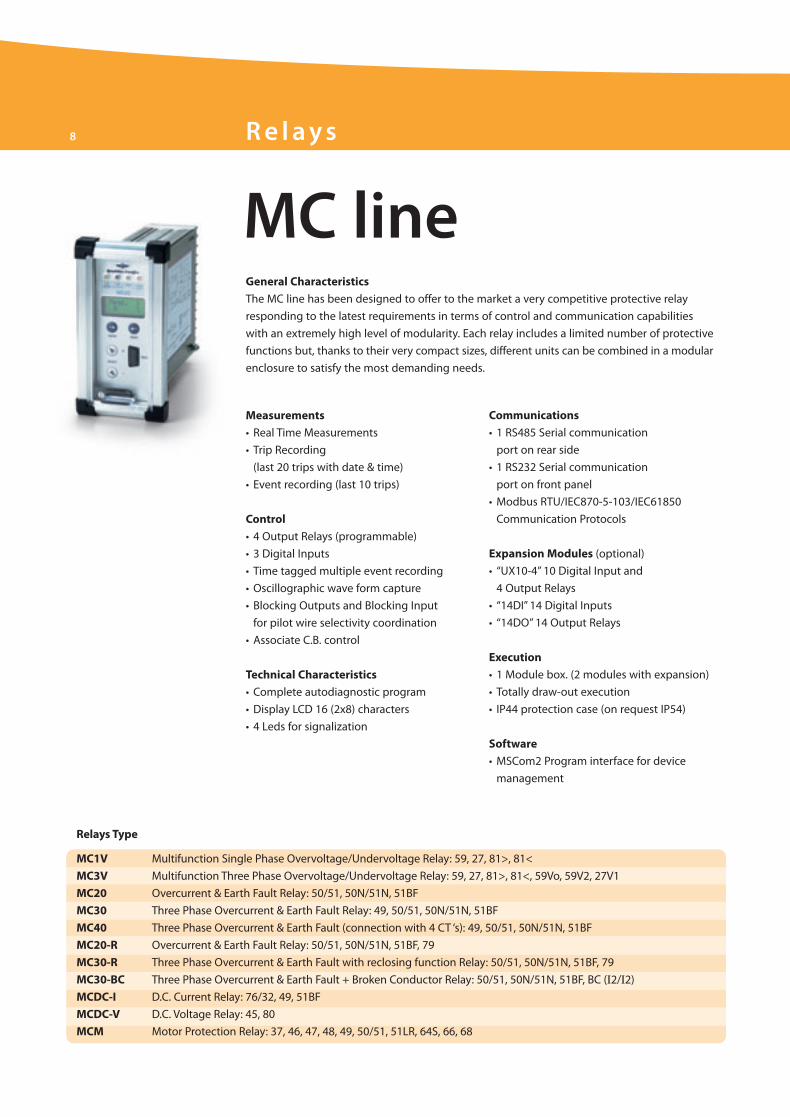
MC line
Measurements
• Real Time Measurements
• Trip Recording
(last 20 trips with date & time)
• Event recording (last 10 trips)
Control
• 4 Output Relays (programmable)
• 3 Digital Inputs
• Time tagged multiple event recording
• Oscillographic wave form capture
• Blocking Outputs and Blocking Input
for pilot wire selectivity coordination
• Associate C.B. control
Technical Characteristics
• Complete autodiagnostic program
• Display LCD 16 (2x8) characters
• 4 Leds for signalization
Communications
• 1 RS485 Serial communication
port on rear side
• 1 RS232 Serial communication
port on front panel
• Modbus RTU/IEC870-5-103/IEC61850
Communication Protocols
Expansion Modules (optional)
• “UX10-4” 10 Digital Input and
4 Output Relays
• “14DI” 14 Digital Inputs
• “14DO”14 Output Relays
Execution
• 1 Module box. (2 modules with expansion)
• Totally draw-out execution
• IP44 protection case (on request IP54)
Software
• MSCom2 Program interface for device
management
MC1V Multifunction Single Phase Overvoltage/Undervoltage Relay: 59, 27, 81>, 81<
MC3V Multifunction Three Phase Overvoltage/Undervoltage Relay: 59, 27, 81>, 81<, 59Vo, 59V2, 27V1
MC20 Overcurrent & Earth Fault Relay: 50/51, 50N/51N, 51BF
MC30 Three Phase Overcurrent & Earth Fault Relay: 49, 50/51, 50N/51N, 51BF
MC40 Three Phase Overcurrent & Earth Fault (connection with 4 CT ‘s): 49, 50/51, 50N/51N, 51BF
MC20-R Overcurrent & Earth Fault Relay: 50/51, 50N/51N, 51BF, 79
MC30-R Three Phase Overcurrent & Earth Fault with reclosing function Relay: 50/51, 50N/51N, 51BF, 79
MC30-BC Three Phase Overcurrent & Earth Fault + Broken Conductor Relay: 50/51, 50N/51N, 51BF, BC (I2/I2)
MCDC-I D.C. Current Relay: 76/32, 49, 51BF
MCDC-V D.C. Voltage Relay: 45, 80
MCM Motor Protection Relay: 37, 46, 47, 48, 49, 50/51, 51LR, 64S, 66, 68
Relays Type
8 R e l ays
General Characteristics
The MC line has been designed to offer to the market a very competitive protective relay
responding to the latest requirements in terms of control and communication capabilities
with an extremely high level of modularity. Each relay includes a limited number of protective
functions but, thanks to their very compact sizes, different units can be combined in a modular
enclosure to satisfy the most demanding needs.
ELT_Brochure_ok.qxd:Layout 1 25-09-2009 14:07 Pagina 8

In= 1A 5AIon= 1A 5A
AUXILIARYSUPPLY
MS-SCE1828-R1
DISPLAY
MICROP.
MC20
1/5A
6
7
4
5
8
9
6
7
4
5
8
9
16
18
1714
15
13
12
2021
1922
10
11
1/5A
1/5A
FUNCTION
F50F51F50NF51N
R1
R1
R2
R3
R4
D3D2
D1
R2
R3
R4INT.FAULT
RS485CA (S+)B (S-)
DIGITALINPUTS
OUTPUTRELAYS
KEYBOARD
BPMC
321
Wiring Diagram
Overall Dimensions (mm)
9
164
135
83 2 195
213
2251 MODULE
PANEL CUT-OUT64X137 (LXH)
ELT_Brochure_ok.qxd:Layout 1 25-09-2009 14:07 Pagina 9
Measurements
• Real Time Measurements
• Trip Recording (last 5 trips with date & time)
• Load Profile recording
Technical Characteristics
The Relay Main Body (RMB) includes:
• 2 Self powered programmable Digital Inputs for remote controls (start, stop, rev., ETC)
• 1 RTD input or User available Digital Input
• 2 Programmable output relays each with one N.O. contact rating 6A
• 1 RS485 port for connection to the communication serial bus (Modbus RTU)
• 1 RS485 port for communication to the Front Face Panel
• 2 Signal Leds, 1 Reset button
The Front Face Panel (FFP) includes:
• 2x16 characters LCD display
• Four Key buttons for local relay management, Four signal leds
• One RS232 port for connection to a local PC (on front side)
• One RS485 port for interconnection with the RMB (on back side)
• Complete autodiagnostic program
Mounting
• DIN46227 (EN50022)
N-DIN-MA Motor Protection Relay: 37, 46, 49, 51, 51LR, 64/51N, 66
N-DIN-F Feeder Protection Relay: 46, 49, 51, 50N/51N, 51BF
N-DIN TO64 D.C. Current Relay with High Sensitivity Hall Effect Transducer: 64, 51BF
Accessories
EX-I/O Input/Output Expansion Module
CPB Profibus Converter Module
TA-DIN Current Transformer
TAR-DIN Current Transformer
Relays Type
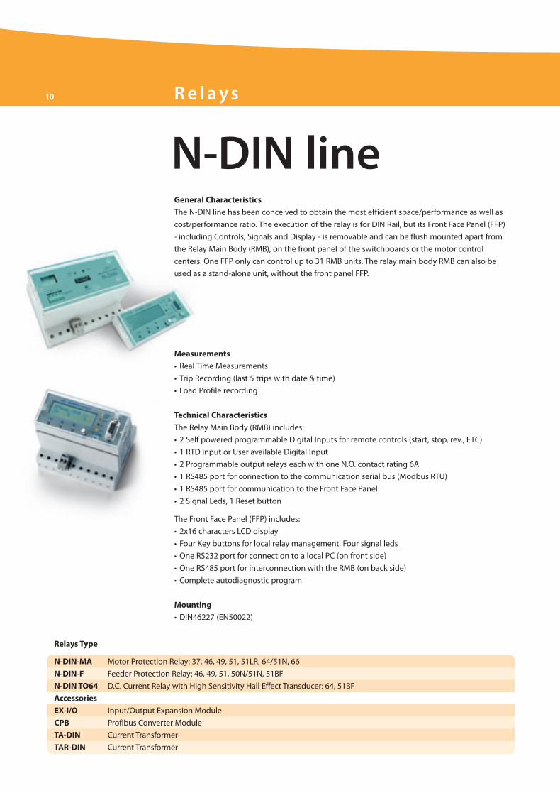
N-DIN line
10 R e l ays
General Characteristics
The N-DIN line has been conceived to obtain the most efficient space/performance as well as
cost/performance ratio. The execution of the relay is for DIN Rail, but its Front Face Panel (FFP)
- including Controls, Signals and Display - is removable and can be flush mounted apart from
the Relay Main Body (RMB), on the front panel of the switchboards or the motor control
centers. One FFP only can control up to 31 RMB units. The relay main body RMB can also be
used as a stand-alone unit, without the front panel FFP.
ELT_Brochure_ok.qxd:Layout 1 25-09-2009 14:07 Pagina 10
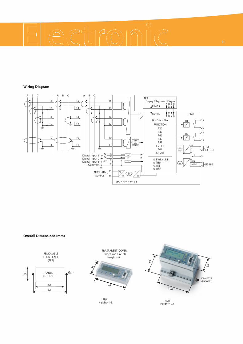
A B C
15
14
13
12
10
11
15
14
13
12
10
11
15
14
13
12
10
11
8976
21
22
A B C A B C
Digital Input 1Digital Input 2Digital Input 3
Common
AUXILIARYSUPPLY
MS-SCE1872-R1
D3
D2D1
RS485A B + 0
A B + 0
FFPDispay / Keyboard / Signal
RS485 RMB
RS485
TOEX-I/O
FUNCTION
PWR / I.R.FTripONOFF
F26F37F46F49F51
F51 LRF64
St. Ctrl
N - DIN - MA R1
R2
19
20
16
17
12
3
45
B (S-)
A (S+)
H
L
C
Wiring Diagram
96
35 O3
90
PANELCUT -OUT
DIN46277(EN50022)
FFPHeight= 16
45
1 60
85
50
RMBHeight= 72
TRASPARENT COVERDimension 45x108
Height = 9REMOVABLEFRONT FACE
(FFP)
1 60
610
Overall Dimensions (mm)
11
ELT_Brochure_ok.qxd:Layout 1 25-09-2009 14:07 Pagina 11

12 R e l ays
U-MLEs D.C. Feeder Manager Relay: 49, 32/76, 80, 45, 64, 79, DI, di/dt, Rapp, Iapp, CMI, LT, BF
U-MLC D.C. Feeder Manager Relay (Italian Railway Certification): 27/59, 32, 45, 49, 64, 76, 79, 80
U-MLC- M D.C. Energy Metering: I, V, W, E
DTMR Differential Transformer Relay: 50/51, 87T, 87N/51N
FMR Feeder Manager Relay: 49, 50/51/67, 50N/51N/67N, 27/59, 81, 46, 59Uo, 51BF, F 27U1, 59U2/47, 79
MMR Motor Manager Relay: 12/14, 37, 27/59, 46, 49, 50/51, 51LR, 51BF, 55, 64, 66, 81
GMR Generator Protection & Management Relay: 21, 24, 27/59, 32, 37, 40, 46, 49, 50/27, 50V/51V, 51BF, 60FL, 64S, 81
Relays Type
Ultra line
Recording
• Event Recording (last 100 events)
• Trip Recording (last 20 trips) complete with
cause of tripping and values of the input
quantities at the moment of trip
• Oscillographic recording of input quantities
(8 channels, 32 sample/cycle, 3 sec each)
Control
• 6 Output Relays user programmable
• 4 Digital Inputs user programmable
• Blocking input and Blocking output for pilot
wire selectivity coordination
• Time tagging resolution 1ms
• Trip circuit supervision
• Associated Circuit Breaker control
(OPEN/CLOSE)
Technical Characteristics
• Graphical Display (128x64 dot)
• 4 Leds for signalization
• Multilanguage Display (English/Italian
standard, available - other on request)
• Complete autodiagnostic program
with dedicated relay
Communications
• 1 RS485 Serial communication port on rear side
• 1 RS232 Serial communication port
on front panel
• Modbus RTU/IEC870-5-103/IEC61850/
TCP-IP Modbus
Communication Protocols
• Canbus port for external additional modules
Expansion Modules (optional)
• “UX10-4” 10 Digital Inputs
and 4 Output Relays
• “14DI” 14 Digital Inputs
• “14DO”14 Output Relays
Execution
• 2 Module box. (3 modules with 1 expansion,
4 modules with 2 expansion)
• IP44 protection case (on request IP54)
• Totally draw-out execution.
Software
• MSCom2 Program interface for device
management
General Characteristics
ULTRA is the top line of Microelettrica Scientifica protective relays; it has been designed
to meet the most demanding specifications for any application in Transmission, Distribution
and Industrial plants. The ULTRA relays are used in all the applications where, besides
the protection, a complete measuring system is needed. Each relay is a multifunctional unit
combining protection, measurements and control. Thanks to the CAN BUS communication
port and to a complete range of additional modules, the relays of this line can perform
a complex input/output logic for interlocking substation system avoiding the use of
an additional PLC. The multiprotocol makes the relay very versatile and suitable
to be implemented in the most common DCS and SCADA systems.
ELT_Brochure_ok.qxd:Layout 1 25-09-2009 14:07 Pagina 12
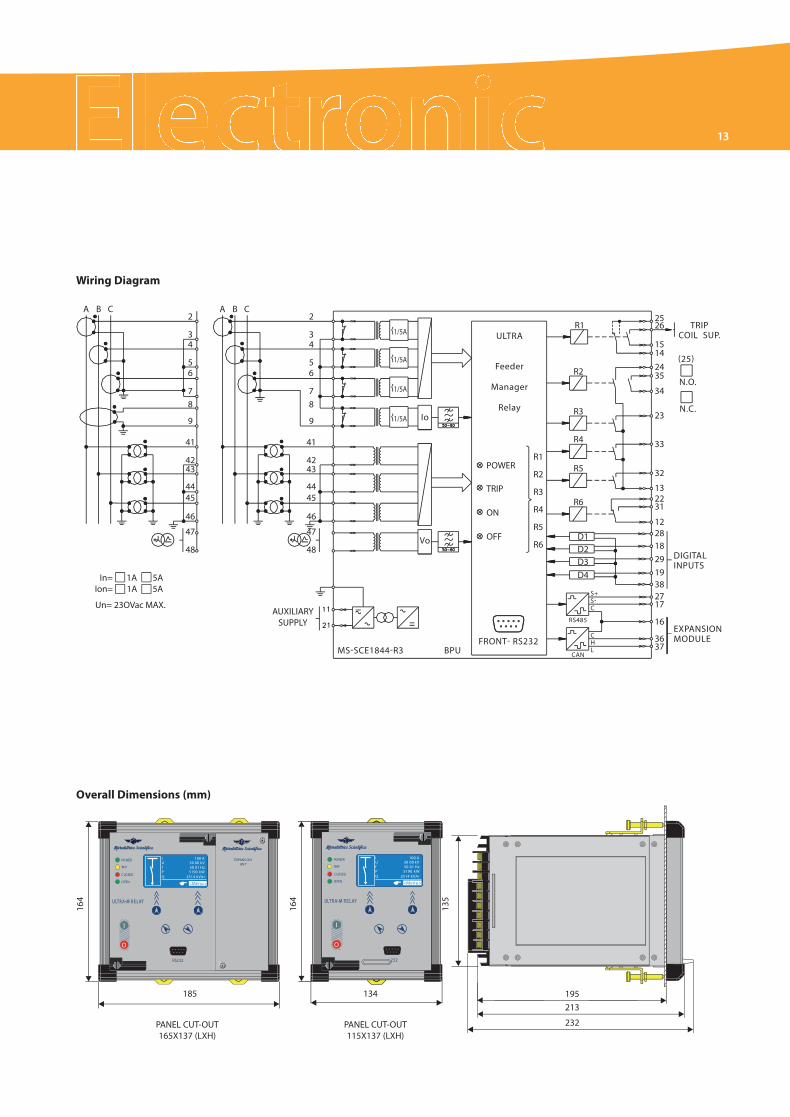
13
A B C A B C
In= 1A 5AIon= 1A 5A
Un= 23OVac MAX.AUXILIARY
SUPPLY
2
34
56
78
9
41
4243
4445
46
47
48
2
34
56
78
9
41
4243
4445
46
47
48
1/5A
1/5A
1/5A
1/5A
MS-SCE1844-R3FRONT- RS232
BPU
S+S-C
CHL
CAN
RS485
Io
Vo
ULTRA
Feeder
Manager
Relay
POWER
TRIP
ON
OFF
R1
R2
R3
R4
R5
R6
R1
R2
R3
R4
R5
R6
D1D2D3D4
DIGITALINPUTS
TRIPCOIL SUP.
(25)
N.O.
N.C.
EXPANSIONMODULE
2526
15142435
34
23
33
32
132231
1228182919382717
16
3637
RS232
OPEN
POWER
TR P
C LOSED
X
U 30 00 kVf 50 01 HzP 5190 kW Q 2514 kVA r
I 100 A
<Menu>
ULT R A-M R E L YULT R A-M R E L AY
I
O
EXPANS ONUN T
232
OPEN
POWER
TRIP
C LOSED
X
U 30 00 kVf 50 01 HzP 5190 kW Q 2514 kVA r
I 100 A
<Menu>
ULT R A-M R E L AYULT R A-M R E L AY
I
O
Wiring Diagram
Overall Dimensions (mm)
185 134
PANEL CUT-OUT165X137 (LXH)
PANEL CUT-OUT115X137 (LXH)
164
164
135
195
213
232
ELT_Brochure_ok.qxd:Layout 1 25-09-2009 14:07 Pagina 13

14 S o f t wa re
MSCom2Interfacing Program
MSCom2 is a communication program forWindows systems allows to:
• Simultaneously comunicate on serial port with up to 250 Microeletrica Scientifica relays
• Save data coming from relays on disk
• Manage the configurations of many relays at the same time and store information
on hard disk
• Print data as tables or diagrams
• Periodically poll the relays and send measurement or event data directly
to the hard disk or a printer
• Access the relays via modem (PC-modem…….. modem-relays)
• Access the relay over TCP/IP protocol
• On-line firmware update
• Prepare off-line relay setting files and directly up load relay’s memory
System Requirements
• IBM P.C. compatible computer
• Pentium 3 microprocessor (recommended Pentium 4 or higher)
• Min. 1 MByte RAM (recommended 2 MByte)
• Min. 200MB free on hard disk
• Min. 1 serial port dedicated to communication
• Resolution min.: 640 x 480, 256 colors (recommended 1024x768, 65535 colors)
• Keyboard
• Mouse
• Operating systems: Microsoft Windows
ULTRA-Line, MC-LIne, M-Line, N-DIN-Line
Supported Lines
ELT_Brochure_ok.qxd:Layout 1 25-09-2009 14:07 Pagina 14
15
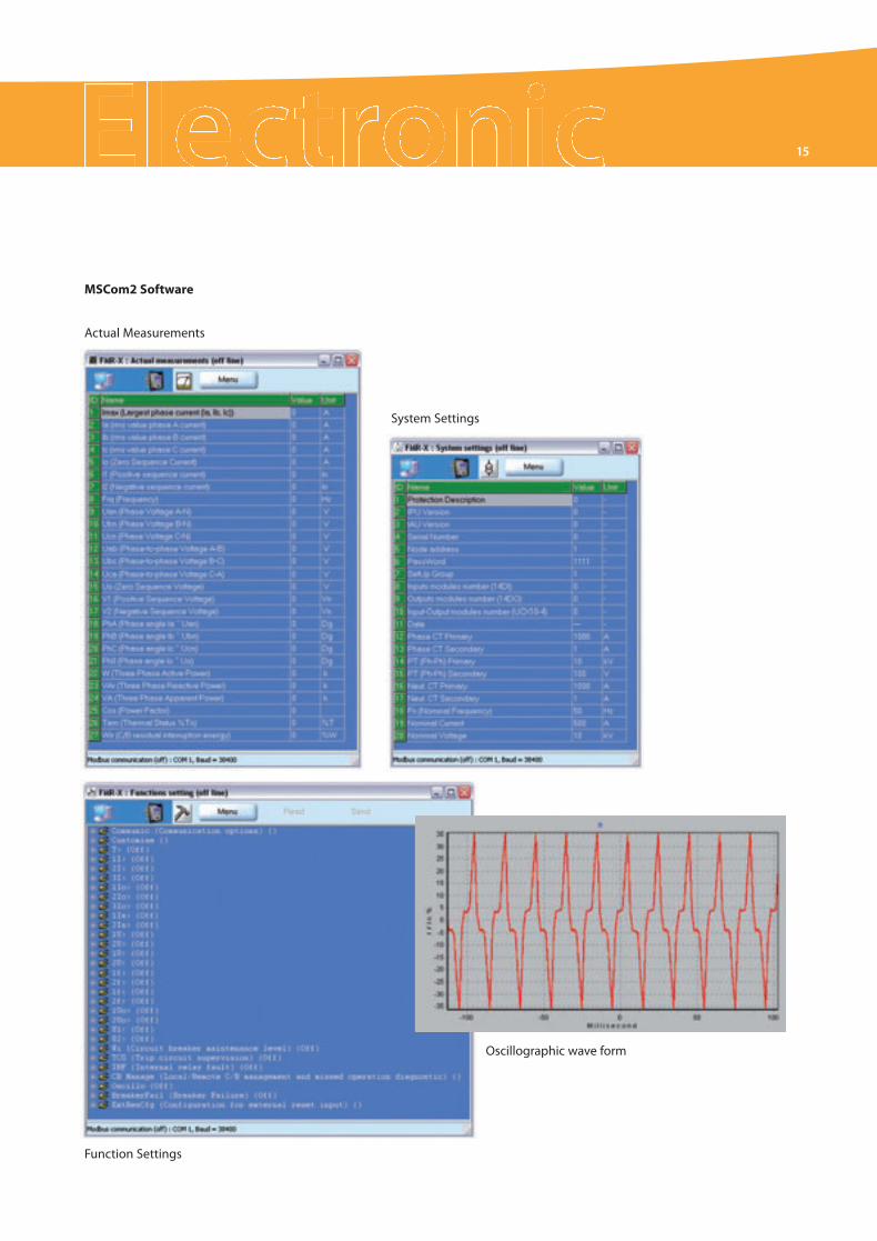
MSCom2 Software
Actual Measurements
Function Settings
System Settings
Oscillographic wave form
ELT_Brochure_ok.qxd:Layout 1 25-09-2009 14:07 Pagina 15

MHCO-TV
For VOLTAGE measurement.
Directly connected to the
high voltage line up to 6kV
through internal voltage
divider
MHCO-TI
For CURRENT measurement.
Connected to the high
voltage line through
a dedicated shunt
(not supplied).
MHCO-TVI
For combined CURRENT
& VOLTAGE measurement.
Connected to the high
voltage line up to 6kV
through internal voltage
divider & through a
dedicated shunt (not
supplied).
The MHCO line includes three models:
Highlights
• HV Transducer for Current & Voltage measurement
• Direct Connection up to 6kV
• Fibre Optic connection between HV transmitter and LV receiver
• Measuring channel fully redundant
• Autoranging Multivoltage Power supply (self-powered version available as optional)
• Compatible with traction application standard
Transmitter Unit
Three different models available, one for each type of transducers (current, voltage and
current/voltage). Directly connected to the High Voltage DC system acquires the input signals
by a redundant input channel and transmit them, after comparison and confirmation of
validity, to the receiver unit through dedicated Fibre Optic connections. It has an autoranging
multivoltage Power supply. As option a self powered version is available; in this case
the power supply is directly taken from the line voltage through a set of dumping resistors.
Receiver Unit
Two models available, respectively suitable to be connected to the current and to the voltage
transmitter by means of a dedicated Fibre Optic connection. The input signal is converted
into 4 linear analogue output signals independently programmable (ie. 0-20/4-20mA etc..).
The setting of this unit can be easily done using our MSCom2 software tool.
MHCO lineDCmeasuring converter
General Characteristics
The DC measuring transducers MHCO are the transducers for high voltage
measurement designed by Microelettrica Scientifica. The MHCO are designed
and manufactured to allow safe and full isolated HV measurement of DC
currents and Voltages. They find their main application in all the DC Traction
Substations (Railways, Tramways and Metro) where, directly connected to
the high voltage systems (750V, 1,5kV and 3kV) gives very accurate and safe
analogue outputs for measuring and protective purposes.
16 Tra n s d u ce r s
ELT_Brochure_ok.qxd:Layout 1 25-09-2009 14:07 Pagina 16
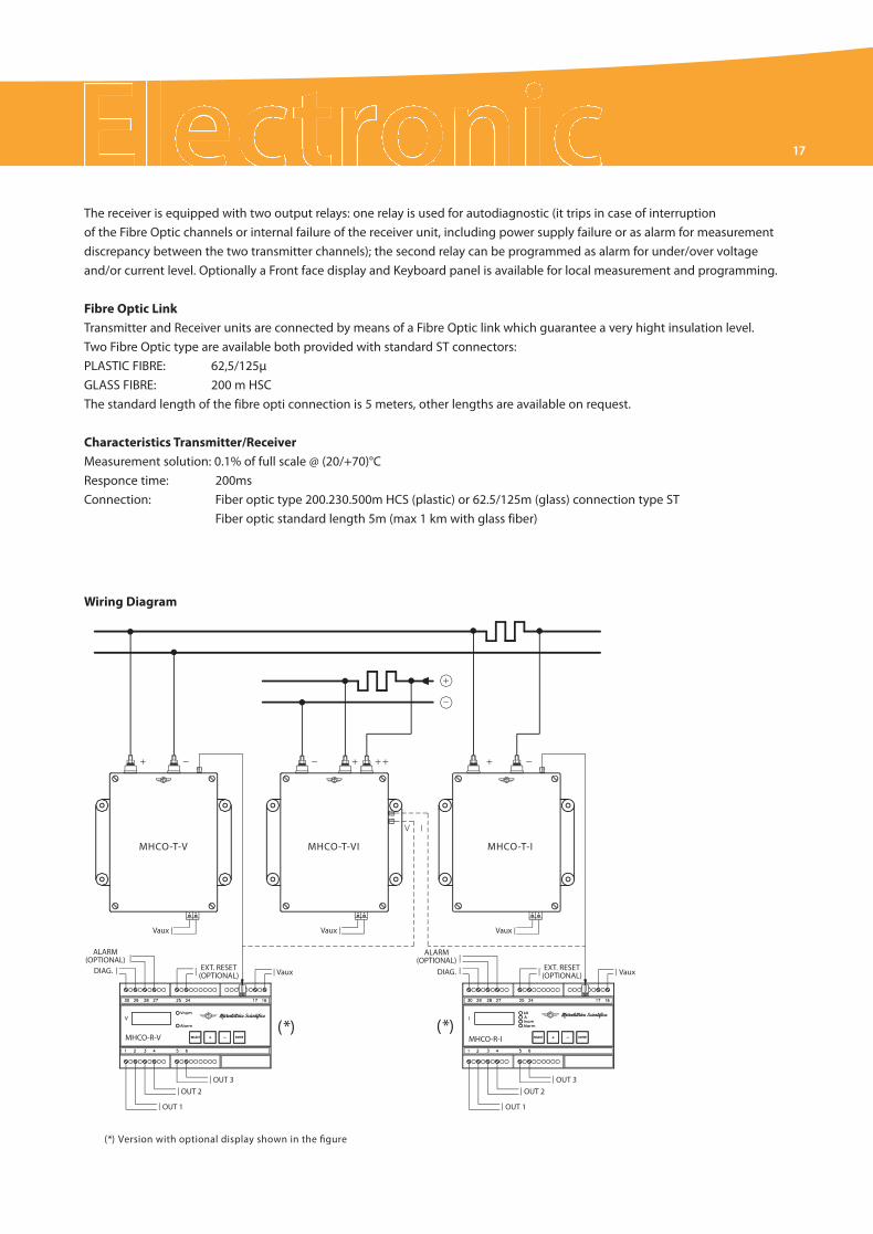
(*) Version with optional display shown in the �gure
(*) (*)
MHCO-T-V
ALARM(OPTIONAL)
DIAG. EXT. RESET(OPTIONAL)
EXT. RESET(OPTIONAL)
MHCO-T-VI MHCO-T-I
MHCO-R-V
OUT 3OUT 2
OUT 1
ALARM(OPTIONAL)
DIAG.
MHCO-R-I
OUT 3OUT 2
OUT 1
Vaux Vaux
Vaux Vaux Vaux
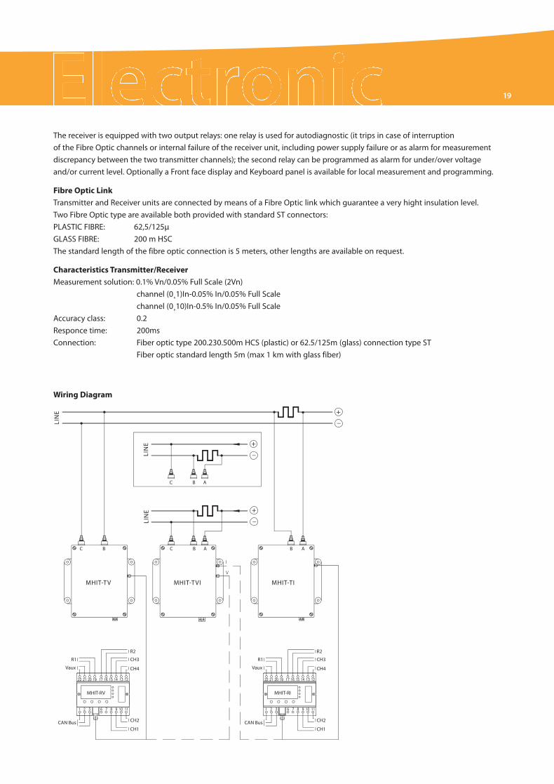
The receiver is equipped with two output relays: one relay is used for autodiagnostic (it trips in case of interruption
of the Fibre Optic channels or internal failure of the receiver unit, including power supply failure or as alarm for measurement
discrepancy between the two transmitter channels); the second relay can be programmed as alarm for under/over voltage
and/or current level. Optionally a Front face display and Keyboard panel is available for local measurement and programming.
Fibre Optic Link
Transmitter and Receiver units are connected by means of a Fibre Optic link which guarantee a very hight insulation level.
Two Fibre Optic type are available both provided with standard ST connectors:
PLASTIC FIBRE: 62,5/125µ
GLASS FIBRE: 200 m HSC
The standard length of the fibre opti connection is 5 meters, other lengths are available on request.
Characteristics Transmitter/Receiver
Measurement solution: 0.1% of full scale @ (20/+70)°C
Responce time: 200ms
Connection: Fiber optic type 200.230.500m HCS (plastic) or 62.5/125m (glass) connection type ST
Fiber optic standard length 5m (max 1 km with glass fiber)
Wiring Diagram
17
ELT_Brochure_ok.qxd:Layout 1 25-09-2009 14:07 Pagina 17
MHIT-V
For VOLTAGE measurement.
Directly connected to the
high voltage line up to 6kV
through internal voltage
divider
MHIT-I
For CURRENT measurement.
Connected to the high
voltage line through
a dedicated shunt
(not supplied)
MHIT-VI
For combined CURRENT
& VOLTAGE measurement.
Connected to the high
voltage line up to 6kV
through internal voltage
divider & through a
dedicated shunt
(not supplied)
The MHIT line includes three models:
Highlights
• HV Transducer for Current & Voltage measurement
• Direct Connection up to 6kV
• Fibre Optic connection between HV transmitter and LV receiver
• Measuring channel fully redundant
• Autoranging Multivoltage Power supply (self-powered version available as optional)
• Compatible with traction application standards
Transmitter Unit
Three different models available, one for each type of transducers (current, voltage and
current/voltage). Directly connected to the High Voltage DC system acquires the input signals
by a redundant input channel and transmit them, after comparison and confirmation of
validity, to the receiver unit through dedicated Fibre Optic connections. It has an autoranging
multivoltage Power supply. As option a self powered version is available; in this case the
power supply is directly taken from the line voltage through a set of dumping resistors.
Receiver Unit
Two models available, respectively suitable to be connected to the current and to the voltage
transmitter by means of a dedicated Fibre Optic connection. The input signal is converted
into 4 linear analogue output signals independently programmable (ie. 0-20/4-20mA etc..).
The setting of this unit can be easily done using our MSCom2 software tool.
MHIT lineDCmeasuring converter
General Characteristics
The DC measuring transducers MHIT are the latest generation of transducers
for high voltage measurement designed by Microelettrica Scientifica. They are
the result of the long experience of Microelettrica in this field with the addition
compared to the previous line (MHCO) of the full redundancy of the measuring
channel which gives a further level of reliability to the product. The MHIT are
designed and manufactured to allow safe and full isolated HV measurement
of DC currents and Voltages. They find their main application in all the DC
Traction Substations (Railways, Tramways and Metro) where, directly
connected to the high voltage systems (750V, 1,5kV and 3kV) gives very
accurate and safe analogue outputs for measuring and protective purposes.
18 Tra n s d u ce r s
ELT_Brochure_ok.qxd:Layout 1 25-09-2009 14:07 Pagina 18
+_
+_
+_
MHIT-TV MHIT-TVI MHIT-TI
LIN
E
LIN
ELI
NE
MHIT-RV MHIT-RI
R1
R2
Vaux Vaux
CH3
CH4
CH2
CH1CAN Bus
R1
R2
CH3
CH4
CH2
CH1CAN Bus
C B C B A B A
C B A
The receiver is equipped with two output relays: one relay is used for autodiagnostic (it trips in case of interruption
of the Fibre Optic channels or internal failure of the receiver unit, including power supply failure or as alarm for measurement
discrepancy between the two transmitter channels); the second relay can be programmed as alarm for under/over voltage
and/or current level. Optionally a Front face display and Keyboard panel is available for local measurement and programming.
Fibre Optic Link
Transmitter and Receiver units are connected by means of a Fibre Optic link which guarantee a very hight insulation level.
Two Fibre Optic type are available both provided with standard ST connectors:
PLASTIC FIBRE: 62,5/125µ
GLASS FIBRE: 200 m HSC
The standard length of the fibre optic connection is 5 meters, other lengths are available on request.
Characteristics Transmitter/Receiver
Measurement solution: 0.1% Vn/0.05% Full Scale (2Vn)
channel (0¸1)In-0.05% In/0.05% Full Scale
channel (0¸10)In-0.5% In/0.05% Full Scale
Accuracy class: 0.2
Responce time: 200ms
Connection: Fiber optic type 200.230.500m HCS (plastic) or 62.5/125m (glass) connection type ST
Fiber optic standard length 5m (max 1 km with glass fiber)
Wiring Diagram
19
ELT_Brochure_ok.qxd:Layout 1 25-09-2009 14:07 Pagina 19
20 Tra n s d u ce r s
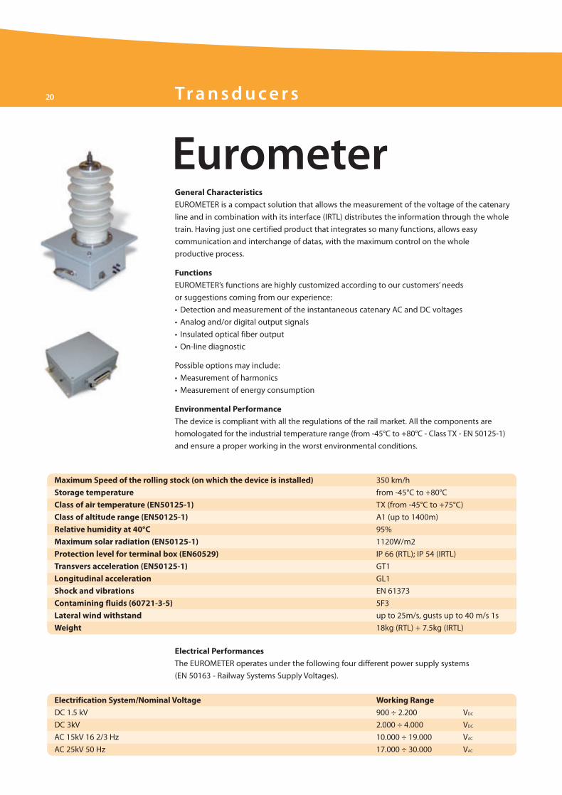
Eurometer
Maximum Speed of the rolling stock (on which the device is installed) 350 km/h
Storage temperature from -45°C to +80°C
Class of air temperature (EN50125-1) TX (from -45°C to +75°C)
Class of altitude range (EN50125-1) A1 (up to 1400m)
Relative humidity at 40°C 95%
Maximum solar radiation (EN50125-1) 1120W/m2
Protection level for terminal box (EN60529) IP 66 (RTL); IP 54 (IRTL)
Transvers acceleration (EN50125-1) GT1
Longitudinal acceleration GL1
Shock and vibrations EN 61373
Contamining fluids (60721-3-5) 5F3
Lateral wind withstand up to 25m/s, gusts up to 40 m/s 1s
Weight 18kg (RTL) + 7.5kg (IRTL)
Electrical Performances
The EUROMETER operates under the following four different power supply systems
(EN 50163 - Railway Systems Supply Voltages).
Electrification System/Nominal Voltage Working Range
DC 1.5 kV 900 ÷ 2.200 VDC
DC 3kV 2.000 ÷ 4.000 VDC
AC 15kV 16 2/3 Hz 10.000 ÷ 19.000 VAC
AC 25kV 50 Hz 17.000 ÷ 30.000 VAC
General Characteristics
EUROMETER is a compact solution that allows the measurement of the voltage of the catenary
line and in combination with its interface (IRTL) distributes the information through the whole
train. Having just one certified product that integrates so many functions, allows easy
communication and interchange of datas, with the maximum control on the whole
productive process.
Functions
EUROMETER’s functions are highly customized according to our customers’ needs
or suggestions coming from our experience:
• Detection and measurement of the instantaneous catenary AC and DC voltages
• Analog and/or digital output signals
• Insulated optical fiber output
• On-line diagnostic
Possible options may include:
• Measurement of harmonics
• Measurement of energy consumption
Environmental Performance
The device is compliant with all the regulations of the rail market. All the components are
homologated for the industrial temperature range (from -45°C to +80°C - Class TX - EN 50125-1)
and ensure a proper working in the worst environmental conditions.
ELT_Brochure_ok.qxd:Layout 1 25-09-2009 14:07 Pagina 20
21
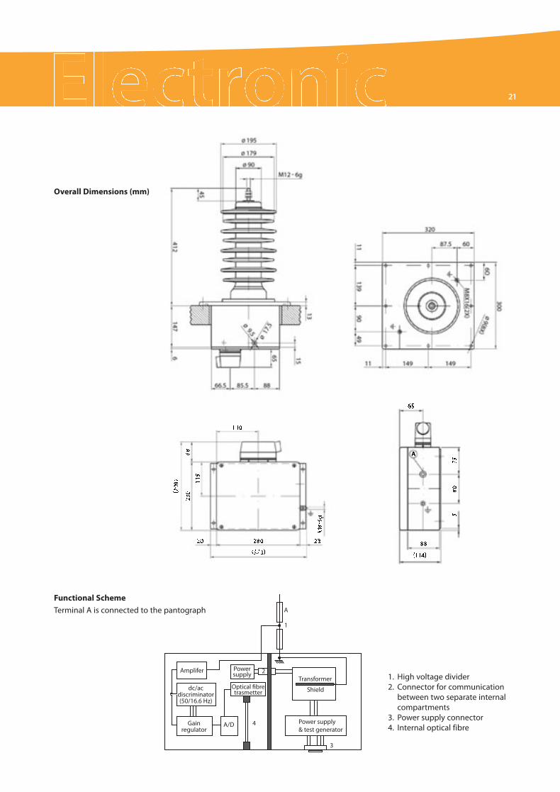
Overall Dimensions (mm)
AmpliferTransformer
Power supply& test generator
Shielddc/acdiscriminator(50/16.6 Hz)
Gainregulator
Optical fibretrasmetter
Powersupply
A/D
2
4
3
1
A
Functional Scheme
Terminal A is connected to the pantograph
1. High voltage divider2. Connector for communication
between two separate internalcompartments
3. Power supply connector4. Internal optical fibre
ELT_Brochure_ok.qxd:Layout 1 25-09-2009 14:07 Pagina 21
22 Tra n s d u ce r s
Integrameter
Maximum Speed of the rolling stock on which the device is installed 350 km/h
Storage temperature from -45°C to +80°C
Class of air temperature (EN50125-1) TX (from -45°C to +75°C)
Class of altitude range (EN50125-1) A1 (up to 1400m)
Relative humidity at 40°C 95%
Maximum solar radiation (EN50125-1) 1120W/m2
Protection level for terminal box (EN60529) IP 66
Transverse acceleration (EN50125-1) GT1 (2m/s2 for less than 50ms, 1m/s2 formore
than 50ms)
Longitudinal acceleration GL1 (max 2 m/s2)
Shock and vibrations EN 61373
Contamining fluids (60721-3-5) 5F3
Lateral wind withstand up to 25m/s, gusts up to 40 m/s 1s
Weight 58kg
Electrical PerformancesThe INTEGRAMETER operates under the following power supply systems(EN 50163 – Railway Systems Supply Voltages).
Electrification System/Nominal Voltage Working Range
DC 1.5 kV 900 ÷ 2.200 VDC
DC 3kV 2.000 ÷ 4.000 VDC
AC 15kV 16 2/3 Hz 10.000 ÷ 19.000 VAC
AC 25kV 50 Hz 17.000 ÷ 30.000 VAC
General CharacteristicsINTEGRAMETER is the last born in our line of on-board metering products and integratesin a single product many functions that were previously divided into multiple componentsfrom different suppliers. Thanks to this patent, Microelettrica has become the one supplierin the world to create and deliver a compact and fully integrated device whose characteristics,both in the high voltage section and in the low voltage metering section, offer maximumreliability and safety.
FunctionsINTEGRAMETER’s functions are highly customized according to our customers’ needsor suggestions coming from our experience:• Detection and measurement of the instantaneous catenary AC and DC voltages• Detection and measurement of the instantaneous catenary AC and DC currents• Measurement of energy consumption• Analog and/or digital output signals• RS422 or RS485 serial outputs• On-line diagnostic through optical fibre
Possible options may include:• Measurement of harmonics• GSM communication• GPRS on board
Environmental PerformanceThe device is compliant with all the regulations of the rail market. All the components arehomologated for the industrial temperature range (from -45°C to +80°C - Class TX - EN 50125-1)and ensure a proper working in the worst environmental conditions.
ELT_Brochure_ok.qxd:Layout 1 25-09-2009 14:07 Pagina 22
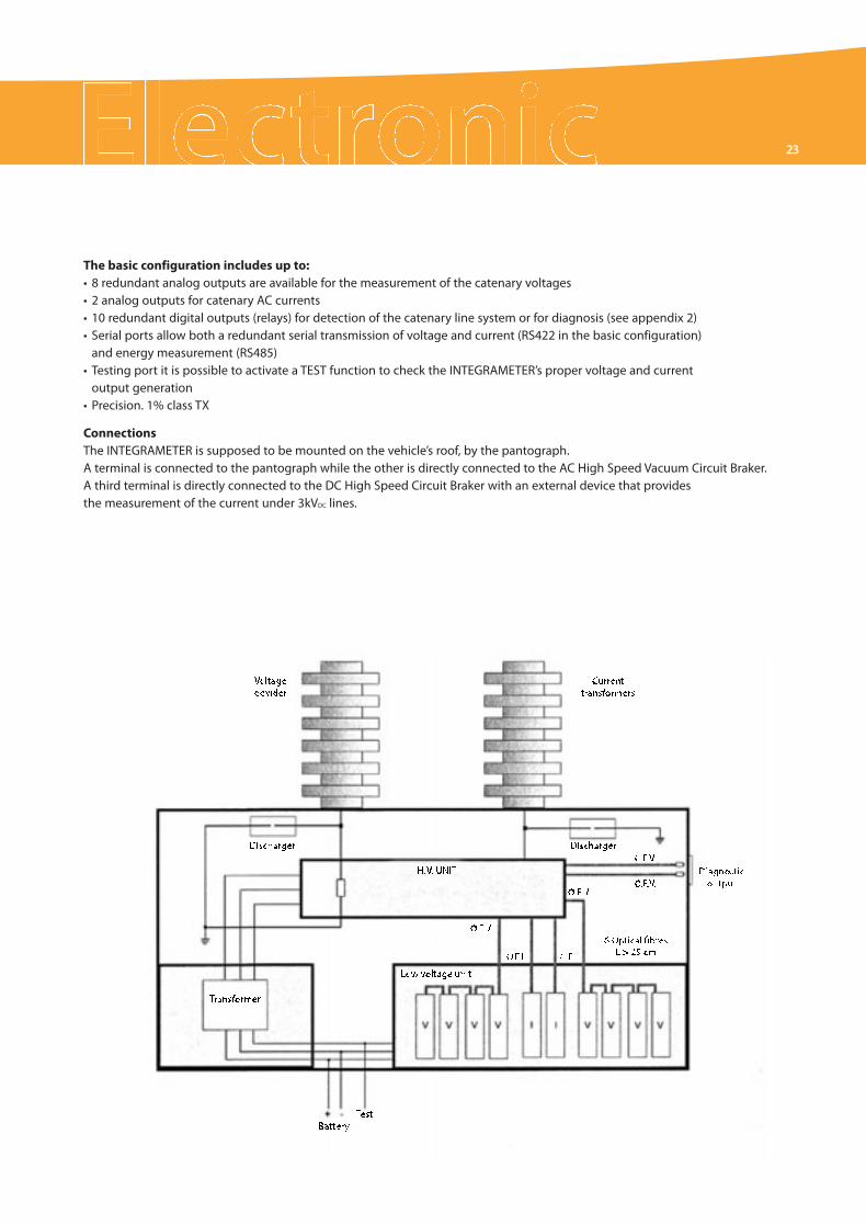
23
The basic configuration includes up to:• 8 redundant analog outputs are available for the measurement of the catenary voltages• 2 analog outputs for catenary AC currents• 10 redundant digital outputs (relays) for detection of the catenary line system or for diagnosis (see appendix 2)• Serial ports allow both a redundant serial transmission of voltage and current (RS422 in the basic configuration)and energy measurement (RS485)
• Testing port it is possible to activate a TEST function to check the INTEGRAMETER’s proper voltage and currentoutput generation
• Precision. 1% class TX
ConnectionsThe INTEGRAMETER is supposed to be mounted on the vehicle’s roof, by the pantograph.A terminal is connected to the pantograph while the other is directly connected to the AC High Speed Vacuum Circuit Braker.A third terminal is directly connected to the DC High Speed Circuit Braker with an external device that providesthe measurement of the current under 3kVDC lines.
ELT_Brochure_ok.qxd:Layout 1 25-09-2009 14:07 Pagina 23
5020
706-
INB
-Sep
t200
9-BT
SAdv
.Tor
ino-
Prin
ted
byGR
AFAR
T
Official Microelettrica Scientifica dealer
AutomaticDoorSystems
For information on salesnetwork and products please visit
www.microelettrica.com
C o m p o n e n t s f o r R a i l o n B o a r d A p p l i c a t i o n C o m p o n e n t s f o r D C S u b s t a t i o n A p p l i c a t i o n C o m p o n e n t s f o r E n e r g y A p p l i c a t i o n C o m p o n e n t s f o r I n d u s t r y A p p l i c a t i o n
Swi tches
ContactorsLTHS lineLTC lineLTHH/LTE/LTP lineLTNS lineN line
DisconnectorsLTHM/P-U/D lineLTMP line
E M C Tr a c t i o n S . r. l .
DC High SpeedCircuit BreakersIR2000IR6000IR6000MPIR6000MLIRAIR2000SVIR6000SV
DC SwitchgearsDIACLAD
Stationary ResistorsNeutral GroundingHarmonic FilterLoad BanksStarting/Braking/DischargeLine Test
On Board ResistorsBrakingContinuous Duty ControlImpulsive Duty Control
Res i s to r s
ELT_Brochure_ok.qxd:Layout 1 25-09-2009 16:56 Pagina 1