Embed Size (px)
Citation preview
either a transition from the ceramic tra- dition of Ticoman to that of Teotihuacan or the influence at Cuicuilco of develop- ing Teotihuacan from some other part of the Valley of Mexico. The most dis- tinctive and abundant ware bears nega- tive painting (black on yellow or black and red on yellow.) with more complex, less curvilinear designs than are typical of Teotihuacan I negative. One type of vessel support has a Teotihuacan I form (8) but the surface lacks the character- istic high polish. Several other wares, in- cluding red, red on yellow, white on red, and blackish brown, display decorative designs, forms, or high polish which are related in some manner as yet incom- pletely understood to standard Teotihua- can I types.
Definite Teotihuacan I sherds are rare and occur in the uppermost levels. These include a scattered assortment of red, negative, polychrome, and fine-line in- cised types.
A small sample of very thin polished red and polished black sherds from the base of Cummings' shaft near the pyra- mid and from the deepest levels of mounds 2 and 4 may represent an earlier ceramic period. These are possibly re- lated to El Arbolillo, but no firm conclu- sion on this is possible until the material has been analyzed further.
A variety of clay figurines support the conclusion on a terminal Preclassic date. Three radiocarbon dates are available for Cuicuilco. De Terra collected a sub- pedregal carbon sample (No. C-200) from the vicinity of the pyramid which yielded a date of 2422 ? 250 years. In January 1957, two wood charcoal sam- ples (Nos. M-663 and M-664) from be- low the pedregal were collected from oc- cupation deposits near mound 2 at Cui- cuilco-B, and these have been dated by the University of Michigan Laboratory as 2040 ? 200 and 1430 ? 200 years old, respectively. Since samples M-663 and M-664 should be the same age, it seems probable that a laboratory error was made in treating one or both samples. Of the two, the oldest (M-663) is more likely to be closer to the actual age. Pifia Chan's date for the termination of the Preclassic (Formative) in the Valley of Mexico is 200 B.c. (9). Since the Cui- cuilco-B material seems to be primarily Late Preclassic but is associated with ceramics which are related to Teoti- huacan I as known from the sites of El Tepelcate (8), the inner hearting of the Pyramid of the Sun at Teotihuacan (10), and to the newly discovered Teotihuacan I complex at Teotihuacan (11), the date of sample M-663 seems to be more nearly correct than that of M-664.
ROBERT F. HEIZER
JAMES A. BENNYHOFF Department of Anthropology, University of California, Berkeley 31 JANUARY 1958
JAMES A. BENNYHOFF Department of Anthropology, University of California, Berkeley 31 JANUARY 1958
References and Notes
1. The assistance of Eusebio Davalos, Ignacio Bernal, and Roman Pifia Chan of the Insti- tuto and Carmen Leonard of the Centro de Investigaciones Antropologicas de Mexico is gratefully acknowledged.
2. The National Geographic Society provided funds to support the recent investigations. Their recent interest may be considered a continuation of their earlier interest in the site, which dates from 1922-25, when Byron Cummings investigated the Cuicuilco Pyramid under the society's auspices. The University of California, through the Committee on Re- search and Associates in Tropical Biogeog- raphy, provided further assistance.
3. A. L. Kroeber, Univ. Calif. Publs. Am. Ar- chaeol. and Ethnol. 17, 401 (1925).
4. B. Cummings, Natl. Geographic Mag. 44, 212, 220 (1923); Univ. Arizona Soc. Sci. Bull. 4, 50 (1933).
5. G. Vaillant, Am. Museum Nat. Hist. An- thropol. Papers 32, plate LXIX (1931).
6. G. Vaillant, ibid. 32, plate LXXV (1931). 7. G. Vaillant, ibid. 35, Fig. 26 (1934). 8. E. Noguera, Am. Antiquity 9, Fig. 2, Nos. 12,
13 (1943). 9. R. P. Chan, Las Culturas Preclasicas de la
Cuenca de Mexico (Fondo de Cultura Eco- nomica, Mexico City, 1955).
10. E. Noguera, El Mexico Antiguo 3 (1935). 11. R. Millon, Boletin del Centro de Investi-
gaciones Antropologicas de Mexico, No. 4 (1957); Am. Antiquity 23, No. 2 (1957).
30 September 1957
Electrolytically Controlled
Device for Dispensing Liquids
Commercially available equipment for dispensing small volumes of liquids continuously for 24 to 72 hours was con- sidered inadequate, or too expensive or cumbersome for certain applications. An instrument was therefore designed to utilize the production of gas by electrol- ysis of water for dispensing solutions aseptically and at any desired rate, by regulation of the electric current (1).
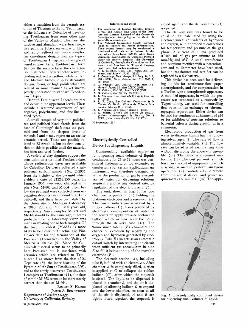
The unit, shown in Fig. 1, has two chambers, a generator (A) holding the platinum electrodes and a reservoir (B). The two chambers are separated by a rubber balloon (C). Gases generated by electrolytic decomposition of water in the generator apply pressure within the balloon which in turn forces the liquid through the delivery tube (D). The 9-mm inner tubing (E) eliminates the chance of explosion by separating the oxygen and hydrogen generated by elec- trolysis. Tube E also acts as an automatic cut-off switch by interrupting the circuit when sufficient gas accumulates in tube E to fill it below the tip of the movable electrode (F).
The electrode section (A), including tube E, is filled with an electrolyte. After chamber A is completely filled, suction is applied at G to collapse the rubber balloon (C), after which the stopcock is closed. The liquid to be dispensed is placed in chamber B, and the air is dis- placed by allowing balloon C to expand
References and Notes
1. The assistance of Eusebio Davalos, Ignacio Bernal, and Roman Pifia Chan of the Insti- tuto and Carmen Leonard of the Centro de Investigaciones Antropologicas de Mexico is gratefully acknowledged.
2. The National Geographic Society provided funds to support the recent investigations. Their recent interest may be considered a continuation of their earlier interest in the site, which dates from 1922-25, when Byron Cummings investigated the Cuicuilco Pyramid under the society's auspices. The University of California, through the Committee on Re- search and Associates in Tropical Biogeog- raphy, provided further assistance.
3. A. L. Kroeber, Univ. Calif. Publs. Am. Ar- chaeol. and Ethnol. 17, 401 (1925).
4. B. Cummings, Natl. Geographic Mag. 44, 212, 220 (1923); Univ. Arizona Soc. Sci. Bull. 4, 50 (1933).
5. G. Vaillant, Am. Museum Nat. Hist. An- thropol. Papers 32, plate LXIX (1931).
6. G. Vaillant, ibid. 32, plate LXXV (1931). 7. G. Vaillant, ibid. 35, Fig. 26 (1934). 8. E. Noguera, Am. Antiquity 9, Fig. 2, Nos. 12,
13 (1943). 9. R. P. Chan, Las Culturas Preclasicas de la
Cuenca de Mexico (Fondo de Cultura Eco- nomica, Mexico City, 1955).
10. E. Noguera, El Mexico Antiguo 3 (1935). 11. R. Millon, Boletin del Centro de Investi-
gaciones Antropologicas de Mexico, No. 4 (1957); Am. Antiquity 23, No. 2 (1957).
30 September 1957
Electrolytically Controlled
Device for Dispensing Liquids
Commercially available equipment for dispensing small volumes of liquids continuously for 24 to 72 hours was con- sidered inadequate, or too expensive or cumbersome for certain applications. An instrument was therefore designed to utilize the production of gas by electrol- ysis of water for dispensing solutions aseptically and at any desired rate, by regulation of the electric current (1).
The unit, shown in Fig. 1, has two chambers, a generator (A) holding the platinum electrodes and a reservoir (B). The two chambers are separated by a rubber balloon (C). Gases generated by electrolytic decomposition of water in the generator apply pressure within the balloon which in turn forces the liquid through the delivery tube (D). The 9-mm inner tubing (E) eliminates the chance of explosion by separating the oxygen and hydrogen generated by elec- trolysis. Tube E also acts as an automatic cut-off switch by interrupting the circuit when sufficient gas accumulates in tube E to fill it below the tip of the movable electrode (F).
The electrode section (A), including tube E, is filled with an electrolyte. After chamber A is completely filled, suction is applied at G to collapse the rubber balloon (C), after which the stopcock is closed. The liquid to be dispensed is placed in chamber B, and the air is dis- placed by allowing balloon C to expand into the lower chamber. As soon as all of the air is displaced, A and B are tightly fitted together, the stopcock is
into the lower chamber. As soon as all of the air is displaced, A and B are tightly fitted together, the stopcock is
closed again, and the delivery tube (D) is opened.
The delivery rate was found to be equal to that calculated by using the electrochemical equivalents of hydrogen and oxygen, with appropriate corrections for temperature and pressure of the gas phase. A current of 1 ma produced 0.0104 ml of gas per minute at 760 mm-Hg and 0?C. A small transformer and selenium rectifier with a potentiom- eter and milliammeter have been used, but the transformer and rectifier can be replaced by a 6-v battery.
This device has been used for deliver- ing liquids for continuous-flow paper electrophoresis, and for compensation in a Tiselius type electrophoresis apparatus. A modified apparatus, in which the gen- erator was connected to a reservoir by Tygon tubing, was used for controlling flow rates in ion-exchange or chroma- tographic separations. Either device can be used for continuous adjustment of pH or for addition of nutrient solutions to bacterial cultures during growth, as in a chemostat.
Electrolytic production of gas from water to dispense liquids has the follow- ing advantages. (i) The rate of flow is almost infinitely variable. (ii) The flow rate can be adjusted easily at any time without disturbing the apparatus assem- bly. (iii) The liquid is dispensed uni- formly. (iv) The cost per unit is much less than the cost of equipment in which a syringe is used to perform analogous operations. (v) Controls may be remote from the actual device, and power re- quirements are minimal. (vi) The appa-
Fig. 1. Electrolytically controlled device for dispensing small volumes of liquid.
233
Fig. 1. Electrolytically controlled device for dispensing small volumes of liquid.
233
ratus can be made small and compact for mounting on individual flasks in an incubator or on a shaker for adding acid, alkali, or other reagents during in- cubation of bacterial cultures. Only light leads are needed to service the units and, if several units are to be used, as for replicate flasks, addition will be identical in all flasks if the electrodes are wired in series. (vii) There are no moving parts which need lubrication.
ROBERT J. HECKLY Naval Biological Laboratory, School of Public Health, University of California, Berkeley
Reference
1. This work was supported by a contract between the University of California and the Office of Naval Research. The opinions contained in this report are not to be construed as reflecting the views of the Navy Department or the Naval Service at large.
23 September 1957
Radiation-Induced Reactions of
Potassium Bromide with Air
Pressed discs of potassium bromide (I) showed selective absorption in the 4000 to 650-K (2) infrared region after irradiation with 1.5-Mev electrons in the presence of air, oxygen, nitrogen, helium, or carbon dioxide. The samples received about 1021 ev/g at a dose-rate of about 1019 ev/min. In all experiments the po- tassium bromide "windows" became less transparent as devitrification, with con- sequent scattering, proceeded. In addi- tion, there was decreased absorbance of the only bands initially present-those centered at 3430 and 1630 K, which were due to adsorbed water or to oc- cluded water retained by the potassium bromide despite careful desiccation, or to both. These results were produced also by heating the discs several hun- dred degrees. The rate of devitrification decreased as the rate of heating was de- creased. The "windows" were restored to the glass-clear condition by repress- ing. While loss of water and devitrifica- tion were the only effects noted for ex- periments conducted in the three gases last named, in oxygen and in air, radi- ation-induced chemical reactions oc- curred.
When a potassium bromide "window" was irradiated in ordinary laboratory air, new bands appeared in the infrared absorption spectrum, with maxima at 1360, 1260, 830, 1440, 1765, and 2340 K, in order of decreasing magnitude. Part of the pattern was unstable and shifted rapidly: peaks at 1385 and 825 K ap- peared and grew at the expense of the
ratus can be made small and compact for mounting on individual flasks in an incubator or on a shaker for adding acid, alkali, or other reagents during in- cubation of bacterial cultures. Only light leads are needed to service the units and, if several units are to be used, as for replicate flasks, addition will be identical in all flasks if the electrodes are wired in series. (vii) There are no moving parts which need lubrication.
ROBERT J. HECKLY Naval Biological Laboratory, School of Public Health, University of California, Berkeley
Reference
1. This work was supported by a contract between the University of California and the Office of Naval Research. The opinions contained in this report are not to be construed as reflecting the views of the Navy Department or the Naval Service at large.
23 September 1957
Radiation-Induced Reactions of
Potassium Bromide with Air
Pressed discs of potassium bromide (I) showed selective absorption in the 4000 to 650-K (2) infrared region after irradiation with 1.5-Mev electrons in the presence of air, oxygen, nitrogen, helium, or carbon dioxide. The samples received about 1021 ev/g at a dose-rate of about 1019 ev/min. In all experiments the po- tassium bromide "windows" became less transparent as devitrification, with con- sequent scattering, proceeded. In addi- tion, there was decreased absorbance of the only bands initially present-those centered at 3430 and 1630 K, which were due to adsorbed water or to oc- cluded water retained by the potassium bromide despite careful desiccation, or to both. These results were produced also by heating the discs several hun- dred degrees. The rate of devitrification decreased as the rate of heating was de- creased. The "windows" were restored to the glass-clear condition by repress- ing. While loss of water and devitrifica- tion were the only effects noted for ex- periments conducted in the three gases last named, in oxygen and in air, radi- ation-induced chemical reactions oc- curred.
When a potassium bromide "window" was irradiated in ordinary laboratory air, new bands appeared in the infrared absorption spectrum, with maxima at 1360, 1260, 830, 1440, 1765, and 2340 K, in order of decreasing magnitude. Part of the pattern was unstable and shifted rapidly: peaks at 1385 and 825 K ap- peared and grew at the expense of the original 1360 and 830 maxima. The rate of shift was greater in humid air. Since the new peaks were characteristic of potassium nitrate dispersed in potassium
234
original 1360 and 830 maxima. The rate of shift was greater in humid air. Since the new peaks were characteristic of potassium nitrate dispersed in potassium
234
original 1360 and 830 maxima. The rate of shift was greater in humid air. Since the new peaks were characteristic of potassium nitrate dispersed in potassium
234
bromide and in Nujol (3), it was inter- esting to speculate on the precursor. The immediate possibilities were: (i) that scattered "isolated" nitrate ions on the surface of the disc migrated to form po- tassium nitrate crystals; (ii) that a meta- stable crystalline phase of potassium nitrate was initially formed on the sur- face under the influence of the crystal- line surface forces of the potassium bro- mide lattice and subsequently recrystal- lized. The latter possibility appeared to be the more likely since it was found (4) that isotropic, triangular microcrys- tals of high melting point, which spon- taneously changed to the normal aniso- tropic form of potassium nitrate, were produced on the surface of potassium bromide crystals irradiated in air with polonium alpha rays.
Although nitrogen dioxide alone (the other nitrogen oxides were inert) re- acted with potassium bromide in a man- ner similar to that of irradiated air, the 100-fold greater rate of reaction at room temperature (20-fold greater at 70?C) in the latter case indicated that energy- rich surface dislocations or excited gase- ous intermediates were involved in the reaction. At constant dose-rate, it was found that the production of infrared- absorbing species decreased as the con- tact time of the irradiated air with the salt diminished. Coupled with the fact that discs irradiated in helium at room temperature did not undergo apprecia- ble postirradiation reaction with air, the view that excited gaseous intermediates were involved gained plausibility.
Of the absorption bands listed above, those centered at 1385, 825, and 1765 K could be identified as belonging to po- tassium nitrate; that centered at 2340 K, which appeared only in windows pre- pared from chemically pure potassium bromide and not in windows made from Harshaw optical grade potassium bro- mide, was undoubtedly produced by car- bon dioxide arising from the radiolysis of organic impurities; that centered at 1260 K, on the basis of other work (5) could be tentatively identified as belong- ing to potassium nitrite produced by radiolysis of potassium nitrate. Although potassium carbonate has been reported (3) to have a very strong absorption band at 1450 K, the 1440 peak here noted did not appear when potassium bromide was irradiated in an atmosphere of carbon dioxide; it did appear when the irradiations were conducted in at- mospheres of oxygen or air. Possibly KNO, which has been reported (6) to absorb at 1445 K, or KOBr was the ab- sorbing species.
The irradiation of a disc in an atmos- phere of dry oxygen produced, in addi-
bromide and in Nujol (3), it was inter- esting to speculate on the precursor. The immediate possibilities were: (i) that scattered "isolated" nitrate ions on the surface of the disc migrated to form po- tassium nitrate crystals; (ii) that a meta- stable crystalline phase of potassium nitrate was initially formed on the sur- face under the influence of the crystal- line surface forces of the potassium bro- mide lattice and subsequently recrystal- lized. The latter possibility appeared to be the more likely since it was found (4) that isotropic, triangular microcrys- tals of high melting point, which spon- taneously changed to the normal aniso- tropic form of potassium nitrate, were produced on the surface of potassium bromide crystals irradiated in air with polonium alpha rays.
Although nitrogen dioxide alone (the other nitrogen oxides were inert) re- acted with potassium bromide in a man- ner similar to that of irradiated air, the 100-fold greater rate of reaction at room temperature (20-fold greater at 70?C) in the latter case indicated that energy- rich surface dislocations or excited gase- ous intermediates were involved in the reaction. At constant dose-rate, it was found that the production of infrared- absorbing species decreased as the con- tact time of the irradiated air with the salt diminished. Coupled with the fact that discs irradiated in helium at room temperature did not undergo apprecia- ble postirradiation reaction with air, the view that excited gaseous intermediates were involved gained plausibility.
Of the absorption bands listed above, those centered at 1385, 825, and 1765 K could be identified as belonging to po- tassium nitrate; that centered at 2340 K, which appeared only in windows pre- pared from chemically pure potassium bromide and not in windows made from Harshaw optical grade potassium bro- mide, was undoubtedly produced by car- bon dioxide arising from the radiolysis of organic impurities; that centered at 1260 K, on the basis of other work (5) could be tentatively identified as belong- ing to potassium nitrite produced by radiolysis of potassium nitrate. Although potassium carbonate has been reported (3) to have a very strong absorption band at 1450 K, the 1440 peak here noted did not appear when potassium bromide was irradiated in an atmosphere of carbon dioxide; it did appear when the irradiations were conducted in at- mospheres of oxygen or air. Possibly KNO, which has been reported (6) to absorb at 1445 K, or KOBr was the ab- sorbing species.
The irradiation of a disc in an atmos- phere of dry oxygen produced, in addi- tion to the aforementioned peak at 1440 K, an infrared absorption band with a maximum at 790 K, which was found to be the principal absorption region of
tion to the aforementioned peak at 1440 K, an infrared absorption band with a maximum at 790 K, which was found to be the principal absorption region of
tion to the aforementioned peak at 1440 K, an infrared absorption band with a maximum at 790 K, which was found to be the principal absorption region of
potassium bromate when it was dispersed in potassium bromide or Nujol (3). This absorption did not appear when the irra- diations were conducted in dry or moist air.
A. RUSSELL JONES Chemistry Division, Oak Ridge National Laboratory, Oak Ridge, Tennessee
References and Notes
1. M. M. Stimson and M. I. O'Donell, J. Am. Chem. Soc. 74, 1805 (1952); U. Schiedt and H. Reinwein, Z. Naturforsch. 7b, 270 (1952).
2. The convention "kayser" (symbol K) as a name for the reciprocal centimeter unit of wave number has been used: Report of the Joint Commission for Spectroscopy, Rome, Sept. 1952, J. Opt. Soc. Am. 43, 410 (1953).
3. F. A. Miller and C. H. Wilkins, Anal. Chem. 24, 1253 (1952).
4. R. Blich, Osterr. Akad. Wiss. Math.-naturw. Kl. Sitzber. Abt. Ila, 162, 99 (1953); L. Wien- inger and N. Adler, Acta Phys. Austriaca 4, 81 (1950).
5. A description of this work is in preparation. 6. D. J. Millen, C. Polydoropoulos, D. Watson,
Proc. Chem. Soc. 1957, 18 (1957). 30 September 1957
Mechanism of Immune Hemolysis: Recognition of Two Steps in the Conversion of EAC', 4, 2 to E*
In recent publications from this labo- ratory (1) it has been established that the lysis of sheep erythrocytes (E) by Forssman antibody (A) and guinea pig complement (C') is the result of a series of successive reaction steps, as follows:
E+A - -> EA E+A - -> EA E+A - -> EA (1) (1) (1) Ca++
EA + C'1, 4 ---- EAC'i, 4 (2) Mg++
EAC', 4 + C'2 -- - EAC'1, 4,2 (3)
EAC', 4,2 + C'3 -----> E* (4) L+ inactive product (4a)
E* --- ghost + hemoglobin (5)
In this scheme C',, Ct2, C'3, and C'4 rep- resent the four recognized components of complement (2). Ca++ and Mg++ have been found to function in steps 2 and 3, respectively. E* refers to an activated or damaged cell which eventually hemo- lyzes without further interaction with complement from the fluid phase. The conversion of EAC'1, 4,2 to E* by C'3 has been found to proceed without re- quirement of a divalent cation such as Ca++ or Mg++, and hence can take place in the presence of 0.01M ethylenedia- mine tetraacetate (EDTA). As a source of C'3, either C'y (guinea pig serum lacking C'1 and C'4) or whole guinea pig serum in the presence of 0.01M EDTA has been used. The identification of C'3 as the component which interacts with EAC', 4,2 to form E* (3) is based on the observation that EAC', 4 2 can be hemolyzed by R1, R2, or R4, but not
by R3 (4). SCIENCE, VOL. 127
Ca++ EA + C'1, 4 ---- EAC'i, 4 (2)
Mg++ EAC', 4 + C'2 -- - EAC'1, 4,2 (3)
EAC', 4,2 + C'3 -----> E* (4) L+ inactive product (4a)
E* --- ghost + hemoglobin (5)
In this scheme C',, Ct2, C'3, and C'4 rep- resent the four recognized components of complement (2). Ca++ and Mg++ have been found to function in steps 2 and 3, respectively. E* refers to an activated or damaged cell which eventually hemo- lyzes without further interaction with complement from the fluid phase. The conversion of EAC'1, 4,2 to E* by C'3 has been found to proceed without re- quirement of a divalent cation such as Ca++ or Mg++, and hence can take place in the presence of 0.01M ethylenedia- mine tetraacetate (EDTA). As a source of C'3, either C'y (guinea pig serum lacking C'1 and C'4) or whole guinea pig serum in the presence of 0.01M EDTA has been used. The identification of C'3 as the component which interacts with EAC', 4,2 to form E* (3) is based on the observation that EAC', 4 2 can be hemolyzed by R1, R2, or R4, but not
by R3 (4). SCIENCE, VOL. 127