Embed Size (px)
Citation preview

NOTES
3Before You Begin
READ THESE INSTRUCTIONS
Read all instructions before installing the dishwasher.
For your safety, please read and observe all safety instructions. This guide will help you anticipate electrical, water, and drain connections and help you select the best location for the dishwasher.
QUESTIONS?
1-877-4Electolux (United States and Canada)
INTERNET
For online support and product information, in the U.S. visit www.electroluxusa.com. In Canada, visit www.electroluxca.com.
©2005 Electrolux Major Appliances, North AmericaPost Office Box 212378, Augusta, Georgia 30917, USA All rights reserved. Printed in the USA
NOTEInstaller: Leave instructions with owner.
Owner: Read your dishwasher Use & Care Guide. It contains important safety information for operating this appliance. It also has many suggestions for getting the best results from your dishwasher.
WARNINGTip Over Hazard – Do not use dishwasher until completely installed.Do not push down on open door.Failure to follow this warning can result in serious injury and void your warranty.
4
TABLE OF CONTENTS
Before You Begin .................................................. 3Questions ........................................................... 3
Preparing for Installation ..................................... 5Dimensions ........................................................ 5Materials Provided for All Installation ................. 5Materials Needed for Installation ....................... 5Tools Needed for Installation ............................. 5Installation Tips .................................................. 6Getting Started ................................................... 7
Making the Connections ...................................... 9Locating the Connections .................................. 9Making the Electrical Connection .................... 10Making the Water Connection .......................... 10Making the Drain Connections ..........................11
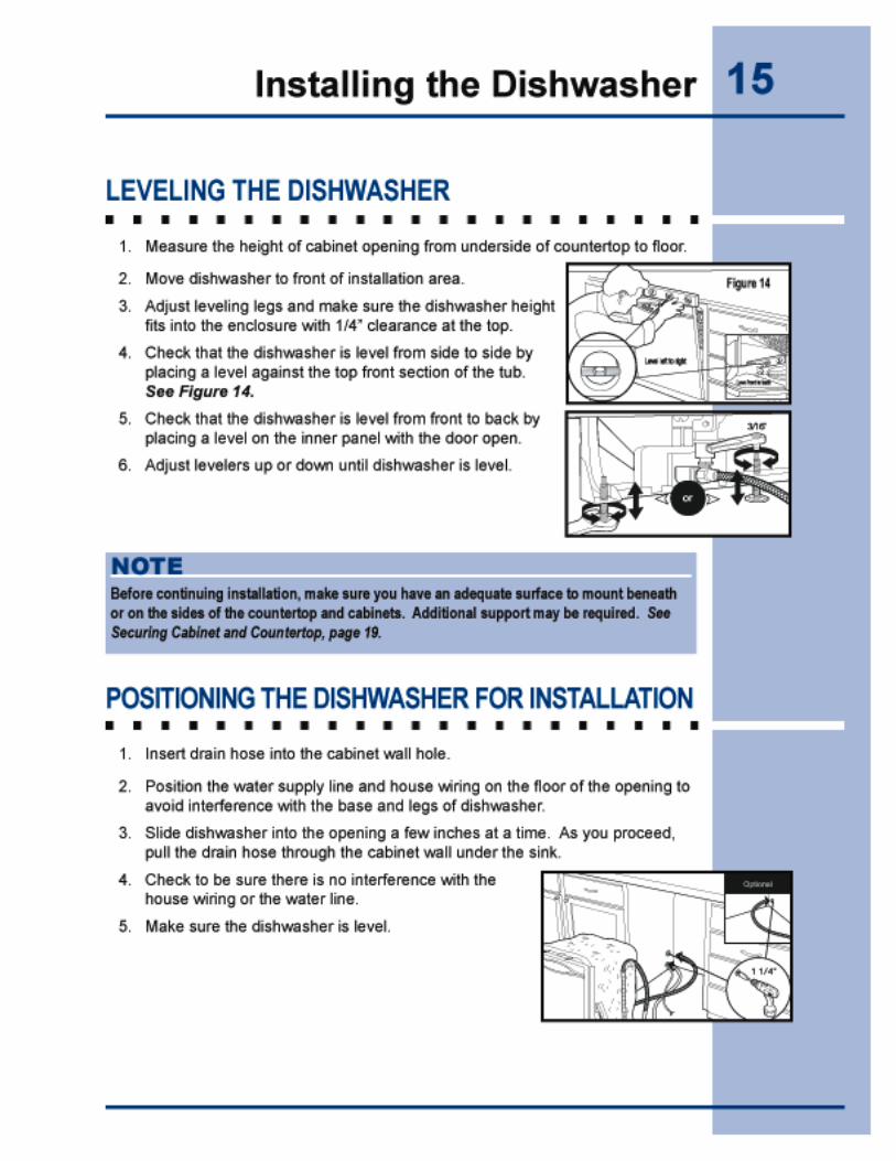
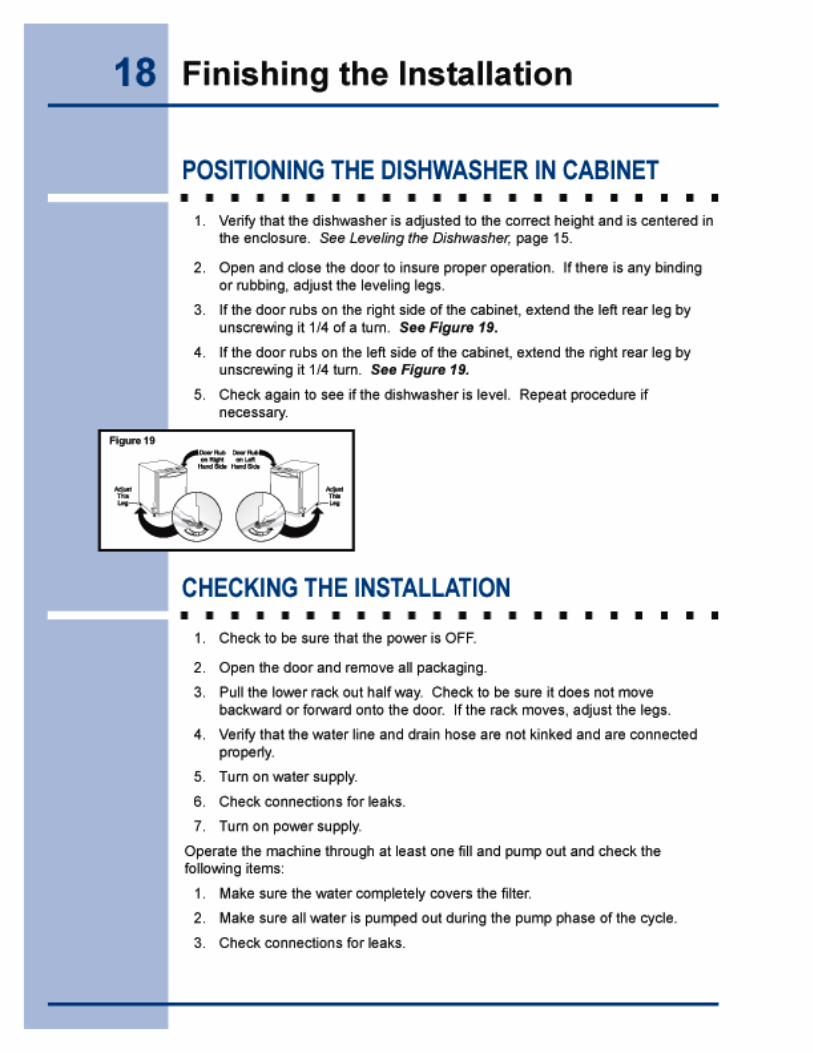
Installing the Dishwasher .................................. 13Removing the Packaging ................................. 13Installing the Leveling Legs ............................. 13 Removing the Foam Motor Support ................. 13Removing the Access Cover ............................ 14Installing the Elbow .......................................... 14Leveling the Dishwasher .................................. 15Positioning the Dishwasher for Installation ...... 15
Finding Information
Finishing the Connections ................................ 16Finishing the Water Connection ....................... 16Finishing the Drain Connection ........................ 16 Finishing the Electrical Connection .................. 17
Finishing the Installation ................................... 18Positioning the Dishwasher in Cabinet ............ 18Checking the Installation .................................. 18
Securing the Dishwasher ................................... 19Securing to Cabinet and Countertop ............... 19
Completing the Installation ............................... 20Installing the Toekick ........................................ 20
Adjusting Trim Plates ........................................ 21
Custom Panel Installation.................................. 22
5Preparing for Installation
BEFORE YOU START
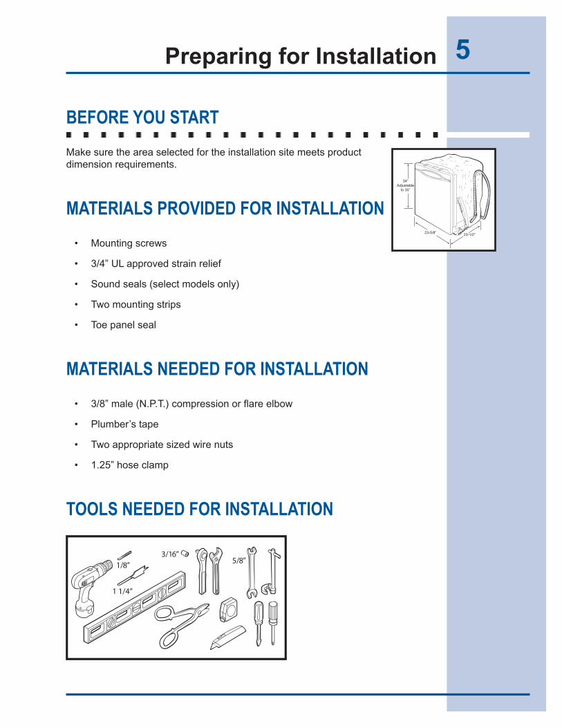
Make sure the area selected for the installation site meets product dimension requirements.
MATERIALS PROVIDED FOR INSTALLATION
• Mounting screws
• 3/4” UL approved strain relief
• Sound seals (select models only)
• Two mounting strips
• Toe panel seal
MATERIALS NEEDED FOR INSTALLATION
• 3/8” male (N.P.T.) compression or flare elbow
• Plumber’s tape
• Two appropriate sized wire nuts
• 1.25” hose clamp
TOOLS NEEDED FOR INSTALLATION
34”Adjustable
to 35”
23-5/8” 23-1/2”
6 Preparing for Installation
INSTALLATION TIPS
Please read all safety instructions before installing your new Electrolux dishwasher.
• Examine the dishwasher and locate the connections. See Locating the Connections, page 9.
• Locate the dishwasher where there is easy access to drain, water, and electrical lines. The best location is on either side of the kitchen sink for access to existing plumbing and ease in loading dishes. See Making the Connections, pages 9-11.
• Electrical, water and drain connections are not the same for all age, brands or models of dishwasher. Check the location and length of home utilities. See Making the Connections, pages 9-11.
• A 15-20 amp, grounded 120 volt AC only electrical supply is required. See Making the Connections, pages 9-11.
• If the dishwasher drain hose will be connected to a food disposer for the first time, remove knock out plug covering disposer inlet. See Making the Connections, pages 9-11.
• Kinked water and drain hoses can cause problems. See Finishing the Connections, page 16.
• Dishwasher need to be connected to a hot water supply with enough water pressure to ensure an adequate fill. See Making the Water Connection, page 10.
• Each home installation differs. You will need additional parts listed above to complete the installation. See Materials Needed for Installation, page 5.
• Flush water line prior to making the final connection to prevent clogging of the inlet valve filter screen. See Finishing the Water Connection, page 16.
• The dishwasher will look, sound and perform best when properly leveled. See Leveling the Dishwasher, page 15.
• Anchor the dishwasher to the countertop and adjacent cabinets. See Securing the Dishwasher, page 19.
WARNINGElectric Shock Hazard – Disconnect electrical power at the fuse box or circuit breaker box before beginning installation. Failure to follow this warning could result in death or serious injury.
7Preparing for Installation
GETTING STARTED
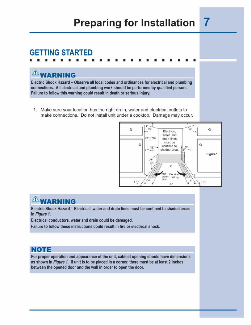
1. Make sure your location has the right drain, water and electrical outlets to make connections. Do not install unit under a cooktop. Damage may occur.
WARNINGElectric Shock Hazard – Observe all local codes and ordinances for electrical and plumbing connections. All electrical and plumbing work should be performed by qualified persons. Failure to follow this warning could result in death or serious injury.
WARNINGElectric Shock Hazard – Electrical, water and drain lines must be confined to shaded areas in Figure 1.Electrical conductors, water and drain could be damaged.Failure to follow these instructions could result in fire or electrical shock.
NOTEFor proper operation and appearance of the unit, cabinet opening should have dimensions as shown in Figure 1. If unit is to be placed in a corner, there must be at least 2 inches between the opened door and the wall in order to open the door.
1 1/2”6”
24”
6”1 1/
2”
71/2”
ElectricalWiring
4”24”min.
18”
341/4” min.
Electrical,water, anddrain linesmust be
confined toshaded area.
HotWaterLine
3”
Figure 1
90°90°
8 Preparing for Installation
2. Remove any carpet from area to provide clearance. Floor should be flat and free from any obstructions.
NOTEDrain, water and electrical lines should be roughed-in before going any further.
NOTEIf the dishwasher is installed at the end of a cabinet line, the dishwasher sides and back must be fully enclosed.
9Making the Connections
LOCATING THE CONNECTIONS
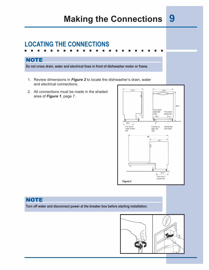
1. Review dimensions in Figure 2 to locate the dishwasher’s drain, water and electrical connections.
2. All connections must be made in the shaded area of Figure 1, page 7.
NOTEDo not cross drain, water and electrical lines in front of dishwasher motor or frame.
NOTETurn off water and disconnect power at the breaker box before starting installation.
1
2
10 Making the Connections
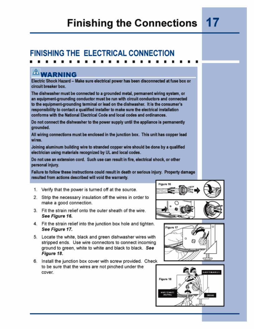
MAKING THE ELECTRICAL CONNECTION
1. The dishwasher operates on a 120 Volt, 60 Hz electrical supply. Provide a separate circuit with fuse or circuit breaker rated for at least 15 amps (20 amps if connected with a disposer), but not more than 20 amps.
2. Note the location of the electrical supply and the dishwasher’s electrical junction box on the right hand underside of the unit. See Figure 2, page 9.
3. Cut the access hole in the shaded area shown in Figure 1, page 7.
4. Pull the electrical cable through the hole into the installation area.
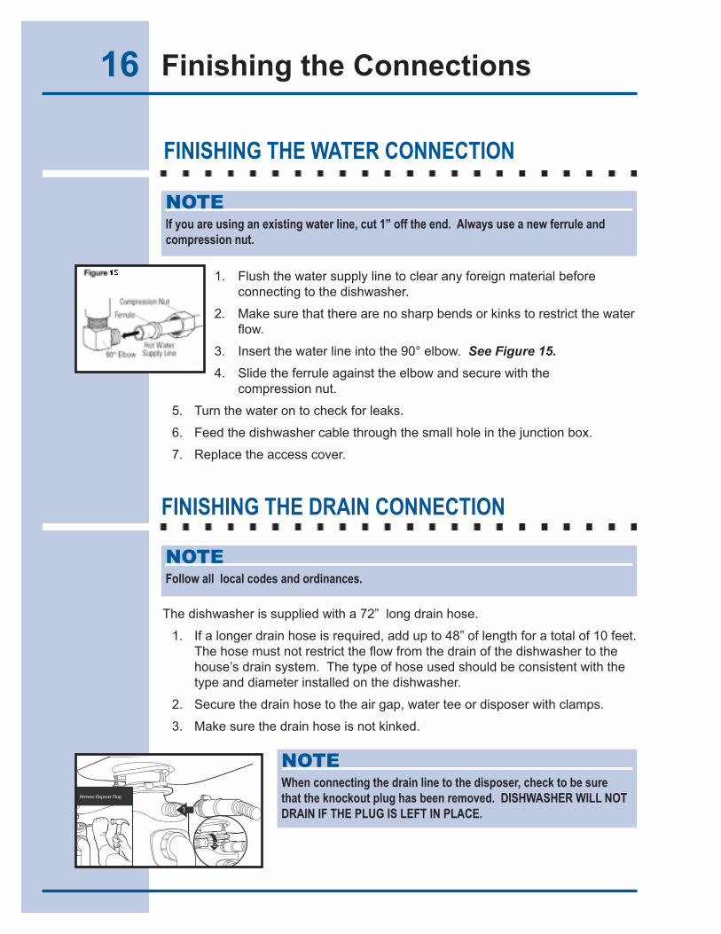
MAKING THE WATER CONNECTION
1. Determine where you connect to the hot water supply. Review Figure 2, page 9 and note the location of the water inlet valve.
2. Be sure water inlet is protected from freezing. If valve freezes and ruptures, flooding may occur.
3. Determine the amount of tubing needed to connect the hot water supply to the unit’s water inlet valve. Copper tubing must have a minimum of 3/8” OD. High-pressure and high-temperature rated plastic tubing with a minimum inner diameter of 1/4” may be used. A shut-off valve installed outside the dishwasher cabinet is recommended. See Figure 3, page 11.
CAUTIONProperty Damage – Do not use the furnished drain hose or a rubber garden hose for the water supply line. Either of the hoses can burst. Flooding may occur and cause property damage. Property damage resulted from actions described will void the warranty.
An existing or new, copper or stainless steel braided line, rated for dishwasher use, should attach the dishwasher to the water supply line.
11Making the Connections
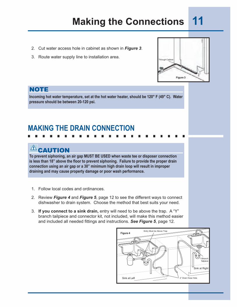
2. Cut water access hole in cabinet as shown in Figure 3.
3. Route water supply line to installation area.
MAKING THE DRAIN CONNECTION
1. Follow local codes and ordinances.
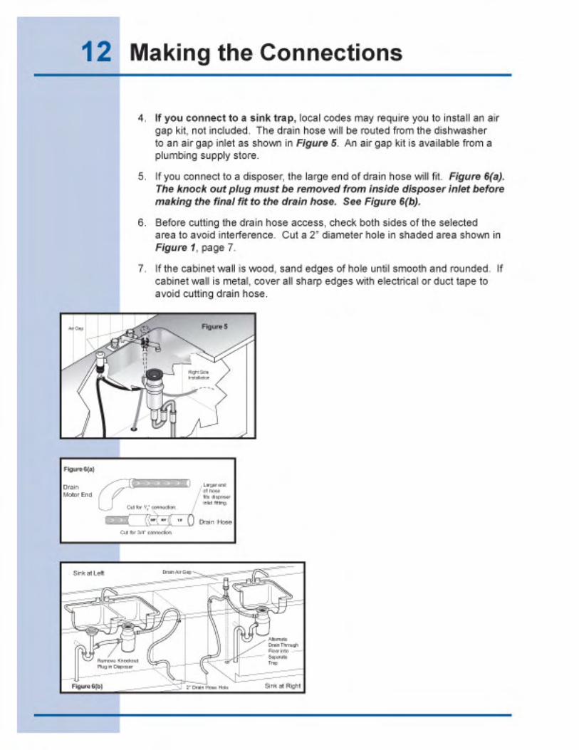
2. Review Figure 4 and Figure 5, page 12 to see the different ways to connect dishwasher to drain system. Choose the method that best suits your need.
3. If you connect to a sink drain, entry will need to be above the trap. A “Y” branch tailpiece and connector kit, not included, will make this method easier and included all needed fittings and instructions. See Figure 5, page 12.
NOTEIncoming hot water temperature, set at the hot water heater, should be 120° F (49° C). Water pressure should be between 20-120 psi.
CAUTIONTo prevent siphoning, an air gap MUST BE USED when waste tee or disposer connection is less than 18” above the floor to prevent siphoning. Failure to provide the proper drain connection using an air gap or a 30” minimum high drain loop will result in improper draining and may cause property damage or poor wash performance.
Figure 3
Through Cabinet
Entry Must be Above Trap
Sink at Left
Figure 4
Y-BranchTailpiece
Sink at Right
2” Drain Hose Hole
16 Finishing the Connections
FINISHING THE WATER CONNECTION
1. Flush the water supply line to clear any foreign material before connecting to the dishwasher.
2. Make sure that there are no sharp bends or kinks to restrict the water flow.
3. Insert the water line into the 90° elbow. See Figure 15.
4. Slide the ferrule against the elbow and secure with the compression nut.
5. Turn the water on to check for leaks.
6. Feed the dishwasher cable through the small hole in the junction box.
7. Replace the access cover.
FINISHING THE DRAIN CONNECTION
The dishwasher is supplied with a 72” long drain hose.
1. If a longer drain hose is required, add up to 48” of length for a total of 10 feet. The hose must not restrict the flow from the drain of the dishwasher to the house’s drain system. The type of hose used should be consistent with the type and diameter installed on the dishwasher.
2. Secure the drain hose to the air gap, water tee or disposer with clamps.
3. Make sure the drain hose is not kinked.
NOTEIf you are using an existing water line, cut 1” off the end. Always use a new ferrule and compression nut.
NOTEFollow all local codes and ordinances.
NOTEWhen connecting the drain line to the disposer, check to be sure that the knockout plug has been removed. DISHWASHER WILL NOT DRAIN IF THE PLUG IS LEFT IN PLACE.1
2
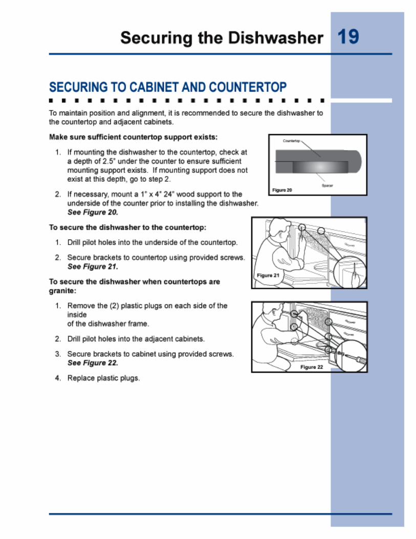
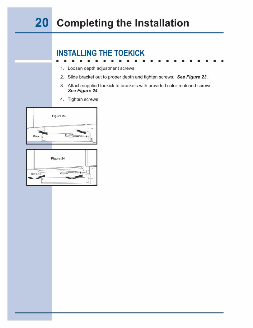
20 Completing the Installation
INSTALLING THE TOEKICK
1. Loosen depth adjustment screws.
2. Slide bracket out to proper depth and tighten screws. See Figure 23.
3. Attach supplied toekick to brackets with provided color-matched screws. See Figure 24.
4. Tighten screws.
Figure 23
Figure 24
Figure 23
Figure 24
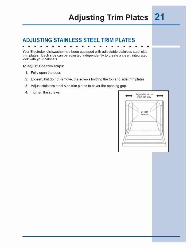
21Adjusting Trim Plates
ADJUSTING STAINLESS STEEL TRIM PLATES
Your Electrolux dishwasher has been equipped with adjustable stainless steel side trim plates. Each side can be adjusted independently to create a clean, integrated look with your cabinets.
To adjust side trim strips:
1. Fully open the door.
2. Loosen, but do not remove, the screws holding the top and side trim plates.
3. Adjust stainless steel side trim plates to cover the opening gap.
4. Tighten the screws.Adjust side trim to
meet cabinetry
Loosenscrews
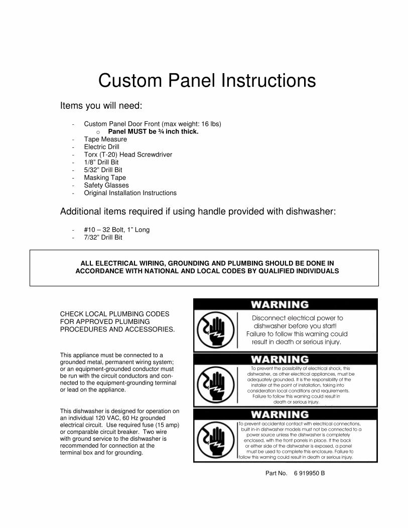
Custom Panel Instructions
Items you will need:
- Custom Panel Door Front (max weight: 16 lbs) o Panel MUST be ¾ inch thick.
- Tape Measure - Electric Drill - Torx (T-20) Head Screwdriver - 1/8” Drill Bit - 5/32” Drill Bit - Masking Tape - Safety Glasses - Original Installation Instructions
Additional items required if using handle provided with dishwasher:
- #10 – 32 Bolt, 1” Long - 7/32” Drill Bit
ALL ELECTRICAL WIRING, GROUNDING AND PLUMBING SHOULD BE DONE IN ACCORDANCE WITH NATIONAL AND LOCAL CODES BY QUALIFIED INDIVIDUALS
CHECK LOCAL PLUMBING CODES FOR APPROVED PLUMBING PROCEDURES AND ACCESSORIES. This appliance must be connected to a grounded metal, permanent wiring system; or an equipment-grounded conductor must be run with the circuit conductors and con- nected to the equipment-grounding terminal or lead on the appliance. This dishwasher is designed for operation on an individual 120 VAC, 60 Hz grounded electrical circuit. Use required fuse (15 amp) or comparable circuit breaker. Two wire with ground service to the dishwasher is recommended for connection at the terminal box and for grounding. Part No. 6 919950 B
������������� ��������������������������������� ������������� ���������� � ����� ���������������� ���� ����������������������������� ��������������� ������� ����������� �������������������������������������� ���������������� �������� ������������������ ������� ������� ��������� ������ ���������������������������� ���������������������� ���������� ���������������������
�������������������������������������������������� ������������������������������������� ������ � ���������� � ������������������������������ ������������������������������������������ ����� �������������� ������� ��� ����� ���� ����������������������������������� ��������� �������������������� ���������������������
������!������������������������� ������� ����������������������" ���������������������������������� �
��������������� ���������������������
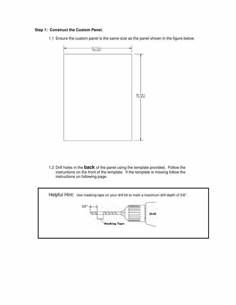
Step 1: Construct the Custom Panel. 1.1 Ensure the custom panel is the same size as the panel shown in the figure below.
1.2 Drill holes in the back of the panel using the template provided. Follow the instructions on the front of the template. If the template is missing follow the instructions on following page.
Helpful Hint: Use masking tape on your drill bit to mark a maximum drill depth of 3/8”.
3/8”
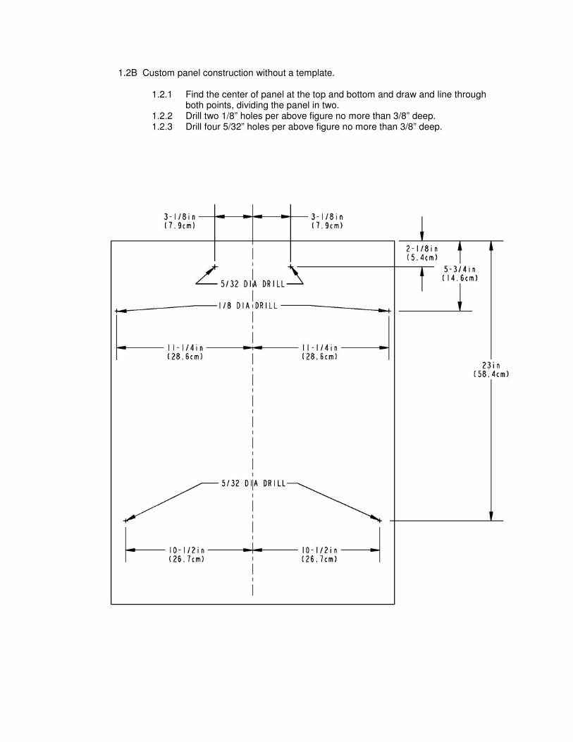
1.2B Custom panel construction without a template.
1.2.1 Find the center of panel at the top and bottom and draw and line through both points, dividing the panel in two.
1.2.2 Drill two 1/8” holes per above figure no more than 3/8” deep. 1.2.3 Drill four 5/32” holes per above figure no more than 3/8” deep.
Step 2: Installing Panel Fasteners.
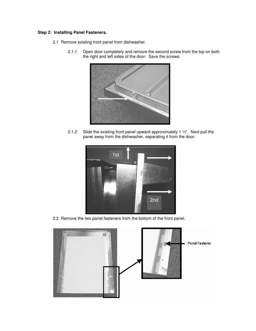
2.1 Remove existing front panel from dishwasher.
2.1.1 Open door completely and remove the second screw from the top on both the right and left sides of the door. Save the screws.
2.1.2 Slide the existing front panel upward approximately 1 ½”. Next pull the panel away from the dishwasher, separating it from the door.
2.2 Remove the two panel fasteners from the bottom of the front panel.
����
� � � �
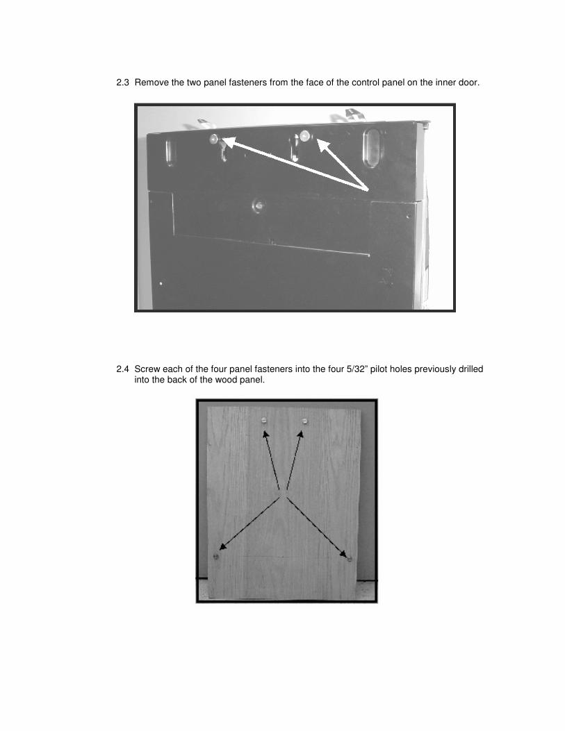
2.3 Remove the two panel fasteners from the face of the control panel on the inner door.
2.4 Screw each of the four panel fasteners into the four 5/32” pilot holes previously drilled into the back of the wood panel.
Step 3: Mounting the Handle (Handle Provided with Dishwasher).
See Step 3B for Custom Handle Installation.
NOTE: Use these instructions ONLY if you are using the same handle provided with
the dishwasher. You will need to purchase two #10 - 32 bolts that are 1 inch long. These can be found at any local hardware store.
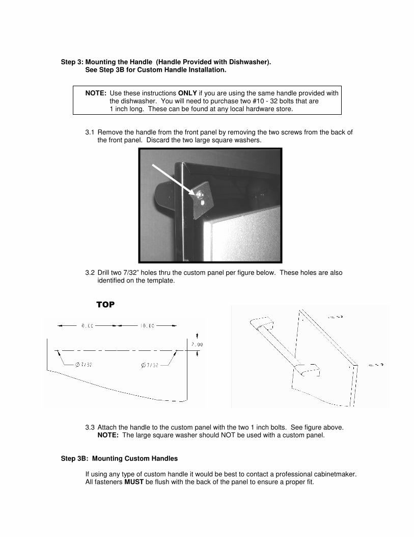
3.1 Remove the handle from the front panel by removing the two screws from the back of the front panel. Discard the two large square washers.
3.2 Drill two 7/32” holes thru the custom panel per figure below. These holes are also identified on the template.
3.3 Attach the handle to the custom panel with the two 1 inch bolts. See figure above. NOTE: The large square washer should NOT be used with a custom panel.
Step 3B: Mounting Custom Handles
If using any type of custom handle it would be best to contact a professional cabinetmaker. All fasteners MUST be flush with the back of the panel to ensure a proper fit.
����
Step 4: Mounting the Custom Panel to the Dishwasher.
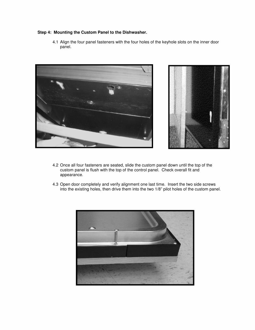
4.1 Align the four panel fasteners with the four holes of the keyhole slots on the inner door panel.
4.2 Once all four fasteners are seated, slide the custom panel down until the top of the custom panel is flush with the top of the control panel. Check overall fit and appearance.
4.3 Open door completely and verify alignment one last time. Insert the two side screws
into the existing holes, then drive them into the two 1/8” pilot holes of the custom panel.
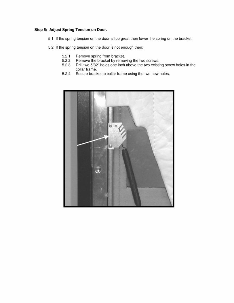
Step 5: Adjust Spring Tension on Door.
5.1 If the spring tension on the door is too great then lower the spring on the bracket. 5.2 If the spring tension on the door is not enough then:
5.2.1 Remove spring from bracket. 5.2.2 Remove the bracket by removing the two screws. 5.2.3 Drill two 5/32” holes one inch above the two existing screw holes in the
collar frame. 5.2.4 Secure bracket to collar frame using the two new holes.