Embed Size (px)
Citation preview
SC I ENCE ROBOT I C S | R E S EARCH ART I C L E
SOFT ROBOTS
1Department of Engineering Mathematics, University of Bristol, Bristol BS8 1QU,UK. 2Bristol Robotics Laboratory, Bristol BS16 1QY, UK.*These authors contributed equally to this work.†Corresponding author. Email: [email protected]
Taghavi et al., Sci. Robot. 3, eaau9795 (2018) 19 December 2018
Copyright © 2018
The Authors, some
rights reserved;
exclusive licensee
American Association
for the Advancement
of Science. No claim
to original U.S.
Government Works
D
Electro-ribbon actuators and electro-origami robotsMajid Taghavi1,2*, Tim Helps1,2*, Jonathan Rossiter1,2†
Origami has inspired novel solutions across myriad fields from DNA synthesis to robotics. Even wider impact can beachievedby active origami, which canmove and change shape independently. However, current active origami and thematerials that power it are both limited in terms of strength, speed, and strain. Here,we introduce an electrostatic activeorigami concept, electro-origami, that overcomes these limitations and allows for simple, inexpensive, lightweight, ef-ficient, powerful, and scalable electronic actuators and lightweight and thin robots. The simplest embodimentof electro-origami, electro-ribbon actuators, can be easily fabricated from any combination of conducting and insulatingmaterial.We present electro-ribbon actuators that can lift 1000 times their own weight, contract by 99.8% of their length, anddeliver specific energy and specific power equivalent to muscle. We demonstrate their versatility in high-stroke andhigh-force morphologies, multiactuator lattices, 3D-printed and paper actuators, self-twisting spirals, and tensileelements inspired by spider silk. More complex electro-origami devices include solenoids, adaptive grippers, roboticcilia, locomoting robots, self-packing deployable structures, origami artificial muscles, and dynamic origami art.
ow
by guest on March 31, 2020http://robotics.sciencem
ag.org/nloaded from
INTRODUCTIONOrigami has been applied to multiple fields, including DNA synthe-sis (1), microfluidics (2), biomedical applications, electric batteries(3), robotics (4), manufacturing, and space structures (5). Active ori-gami, whereby independent motion is driven by internally generatedforces, allows for even greater applicability, enabling self-deployingbiomedical devices (6) and novel artificial muscles (7, 8). Various ac-tuation technologies can deliver forces for active origami (6–12); how-ever, the limitations of these actuation phenomena have resulted inactive origami structures that are weak, slow to cycle, strain-limited,or not made from thin materials. Here, we introduce an electrostaticactive origami concept that overcomes these limitations and deliversstrong and dynamic electro-origami structures made from any com-bination of conducting and insulating materials.
Electrostatic forces have the potential to be extremely large: AsFeynman et al. (13) eloquently put it, electric force is “about a billion-billion-billion-billion” times stronger than gravitational force. Actuatorsdriven by electrostatic forces are characterized by high efficiencies,fast response times, and lowpower requirements. Combdrive actuators,for example, have been used for decades in microelectromechanicalsystems devices (14), but the stroke of these actuators is on the orderof micrometers (15). Larger displacements can be achieved throughthe use of zipping structures, whereby one electrode incrementally de-forms toward a counterelectrode (16–18); however, when these actua-tors have been built at the macroscale, the forces they have been able toexert have been limited (19–21). Liquid-amplified electrostatic actuatorshave demonstrated high actuation forces, showing the potential ofelectrostatic zipping (22, 23). In particular, hydraulically amplifiedelectrostatic actuators have used liquid-amplified electrostatic forcesto deliver fluid pressure in flexible fluidic actuators (22, 24); however,when made into working devices, their contractions are theoreticallylimited to less than 18%, and their nonplanar actuation prevents theiruse in origami structures (25). Electro-origami actuators are fundamen-tally different from these actuators, being driven by purely electrostaticforces with no hydraulic behavior, requiring markedly less liquid di-electric and no encapsulation, allowing for fast, simple fabrication
and radically different actuating morphologies, and delivering contrac-tions exceeding 99%.
RESULTSElectro-origami principle [dielectrophoretic liquidzipping (DLZ)]The fundamental principle of electro-origami is an origami foldwhoseopposing sides are oppositely charged (Fig. 1A and fig. S1A). At thefold hinge, a strong electric field is developed (fig. S1B), and anelectrostatic force is exerted. This electrostatic force is typically notgreat enough to do useful work or even cause visible movement. How-ever, if a small bead of high-permittivity, high–breakdown strengthliquid dielectric is added at the hinge, then it considerably amplifiesthe electrostatic force and causes the hinge to close (Fig. 1, A and B,and movie S1), with the liquid dielectric being driven along as thehinge closes. The overall closing force is coupled to Maxwell pressure,Pº eE2, where e is the dielectric permittivity and E is the electric field(26). The liquid dielectric has two complementary effects: First, it in-creases closing force in proportion to its permittivity relative to air. Inaddition, its breakdown strength is considerably higher than the break-down strength of air. Hence, the addition of liquid dielectric allowshigher electric fields to be sustained because of its higher breakdownstrength, greatly increasing maximum closing force by a factor ofEbreakdown;liquidEbreakdown;air
� �2. Here, silicone oil was used as the liquid dielectric, whose
permittivity and breakdown strength are roughly 2.7 and 6.7 timesgreater than air, respectively, implying that maximum closing forcecould be increased up to 120-fold.
Serendipitously, as the electro-origami fold closes, the amplifyingliquid dielectric bead is kept in place by dielectrophoretic forces (27),which have the effect of drawing high-permittivity materials (in thiscase, the liquid dielectric) into regions of high electric field density(the electro-origami hinge) (28). In this manner, a strong closing forceis generated throughout actuation using only a single bead of liquiddielectric, which greatly reduces device mass compared with fullysubmerged or encapsulated solutions (in experiments, a liquid beadprovided 92% of the electrostatic force compared with a fully sub-merged system). This zipping behavior, whereby dielectrophoreticforces retain a bead of liquid dielectric as it amplifies electrostaticzipping, may be called dielectrophoretic liquid zipping (DLZ).
1 of 12
SC I ENCE ROBOT I C S | R E S EARCH ART I C L E
by guest on March 31, 2020
http://robotics.sciencemag.org/
Dow
nloaded from
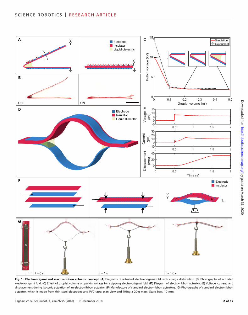
Fig. 1. Electro-origami and electro-ribbon actuator concept. (A) Diagrams of actuated electro-origami fold, with charge distribution. (B) Photographs of actuatedelectro-origami fold. (C) Effect of droplet volume on pull-in voltage for a zipping electro-origami fold. (D) Diagram of electro-ribbon actuator. (E) Voltage, current, anddisplacement during isotonic actuation of an electro-ribbon actuator. (F) Manufacture of standard electro-ribbon actuators. (G) Photographs of standard electro-ribbonactuator, which is made from thin steel electrodes and PVC tape: plan view and lifting a 20-g mass. Scale bars, 10 mm.
Taghavi et al., Sci. Robot. 3, eaau9795 (2018) 19 December 2018 2 of 12
SC I ENCE ROBOT I C S | R E S EARCH ART I C L E
ModelingWedeveloped amathematicalmodel to investigate the effect of the beadof liquid dielectric on the behavior of this system (see the Supplemen-taryMaterials). For two parallel charged plates separated by an insulatorand amedium (fig. S2A), when the insulator is adhered to the insulator-adjacent electrode, the attractive force on the electrodes is given by
F ¼12 emediume0AV2
emediumeinsulator
tinsulator þ tmedium
� �2 ð1Þ
where F is the attractive force; emedium, e0, and einsulator are the permit-tivity of the medium, free space, and the insulator, respectively; A is theplate area; V is the applied voltage; and tinsulator and tmedium are the in-sulator and the medium thickness, respectively. If the insulator is con-
Taghavi et al., Sci. Robot. 3, eaau9795 (2018) 19 December 2018
siderably thinner than the medium (tinsulator ≪ tmedium), the attractiveforce tends toward
F ¼12 emediume0AV2
tmedium2 ð2Þ
which is equivalent to the attractive force between two parallel chargedplates separated by a medium only. In contrast, if the medium is con-siderably thinner than the insulator (tmedium ≪ tinsulator), the attractiveforce tends toward
F ¼12 e0AV
2
emediumtinsulatoreinsulator
� �2 ð3Þ
by guest on March 31, 2020
http://robotics.sciencemag.org/
Dow
nloaded from
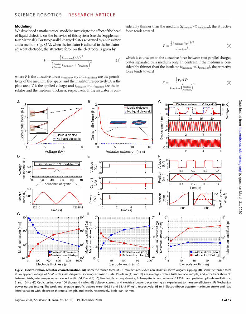
Fig. 2. Electro-ribbon actuator characterization. (A) Isometric tensile force at 0.1-mm actuator extension. (Insets) Electro-origami zipping. (B) Isometric tensile forceat an applied voltage of 6 kV, with inset diagrams showing extension state. Points in (A) and (B) are averages of five trials for one sample, and error bars show SDbetween trials; intersample variance was low (fig. S4, D and E). (C) Bandwidth testing, showing full-amplitude contraction at 0.125 Hz and partial-amplitude oscillation at5 and 10 Hz. (D) Cyclic testing over 100 thousand cycles. (E) Voltage, current, and electrical power traces during an experiment to measure efficiency. (F) Mechanicalpower output testing. The peak and average specific powers were 103.51 and 51.45 W kg−1, respectively. (G to I) Electro-ribbon actuator maximum stroke and loadlifted variation with electrode thickness, length, and width, respectively. Scale bar, 10 mm.
3 of 12

SC I ENCE ROBOT I C S | R E S EARCH ART I C L E
httD
ownloaded from
In the case of electro-origami, the medium (liquid dielectric or air)thickness ranges smoothly from zero at the fold hinge to considerablylarger than the insulator thickness. Such a system cannot be solved an-alytically, so we developed a finite element model of a zipping electro-origami fold based on Eq. 1 and Euler-Bernoulli beam theory (figs. S2, Band C, and S3, and the Supplementary Materials). The model confirmsthat only a small droplet of liquid dielectric is required to achieve con-siderable force amplification: A tiny bead of only 0.2 ml reducedpull-in voltage by more than 80%, asymptotically approaching thefully submerged pull-in voltage of 1700 V (Fig. 1C and the Supple-mentaryMaterials). Experimental results for an identical system (fig.S1C) confirmed the validity of the model (Fig. 1C).
CharacterizationFundamentally, electro-origami allows high-strength zipping actua-tion of prefolded origami structures, enabling a whole range of activeorigami designs. To characterize the actuation properties of the electro-origami concept in a working device, we began with a simple practicalembodiment, the electro-ribbon actuator (Fig. 1D), that comprised twoelectrodes and a single insulator. When voltage was applied to anelectro-ribbon actuator, the opposing electrodes were charged, andthe actuator contracted (Fig. 1E). Electro-ribbon actuators could be eas-ily fabricated by using any combination of flexible insulating and flex-
Taghavi et al., Sci. Robot. 3, eaau9795 (2018) 19 December 2018
ible conductive material, including indium-tin-oxide (ITO)–coatedpolyethylene terephthalate (PET), polyimide, graphene-loaded andpure polylactic acid (PLA), and pencil and office paper (table S1).
Our standard actuator used thin steel electrodes and polyvinyl chlo-ride (PVC) tape (Fig. 1F). When electro-ribbon actuators contractedfully, contraction approached 100% because of their extremely lowthickness when contracted (Fig. 1G and movie S2). Actuation timewas affected by applied voltage (fig. S4A) and load (fig. S4B): Highervoltages sustained stronger fields, which increased the contractionspeed of the actuator. Lighter loads decreased the electro-origamihinge angle, which similarly increased field strength, increasingcontraction speed. Figure 2 (A and B) shows results from isometrictesting of a standard electro-ribbon actuator (experimental setup asshown in fig. S4C); addition of a small bead (around 0.2 ml) of liquiddielectric at each electro-origami fold hinge markedly increased con-tractile force by a factor of up to 37.
We demonstrated full-amplitude cyclic actuation at a bandwidthof 0.125 Hz (Fig. 2C and movie S3). Higher-frequency operation canbe achieved if a lower-amplitude stroke is acceptable: We demon-strated 5-Hz cyclic operation at 9.7% of full amplitude and 10-Hz cyclicoperation at 0.62% of full amplitude (Fig. 2C). The charging time ofelectro-origami actuators was extremely fast and did not notably limitbandwidth; bandwidth limitationwas dominated bymechanical inertia,
by guest on March 31, 2020
p://robotics.sciencemag.org/
Fig. 3. Electro-ribbon actuators made with different stiffness and from different materials. (A) A high-stress actuator lifting 410 g. (B) A high-stroke actuator lifting10.75 g. (C) Electro-ribbon actuator made from ITO-coated PET lifting a 5-g mass. (D) A 3D printed electro-ribbon actuator, featuring 3D-printed graphene-loaded PLAconductors and a 3D-printed pure PLA insulator. (E) Electro-ribbon actuator made from pencil and paper lifting a 3-g mass. Scale bars, 10 mm.
4 of 12
SC I ENCE ROBOT I C S | R E S EARCH ART I C L E
adhesive and cohesive forces, and the availability of liquid dielectric. Assuggested by the model (Fig. 1C), as long as a small quantity of liquiddielectric remains at the electro-origami fold hinge, performance is high.However, if all the liquid leaks away, then performance is impaired. Forlong-term actuation, this can be easily addressed by adding features toretain the liquid dielectric between cycles. For example, we investigated
Taghavi et al., Sci. Robot. 3, eaau9795 (2018) 19 December 2018
surface structure modifications: perpendicular channel-shaped cutoutsin the insulator layer that act as liquid reservoirs. An actuator modifiedin this manner delivered 100,000 isometric actuation cycles with neg-ligible variation in force (Fig. 2D). After 100,000 cycles, the actuationforce exerted was still roughly 10 times greater than the force when noliquid dielectric was present.
by guest on March 31, 2020
http://robotics.sciencemag.org/
Dow
nloaded from
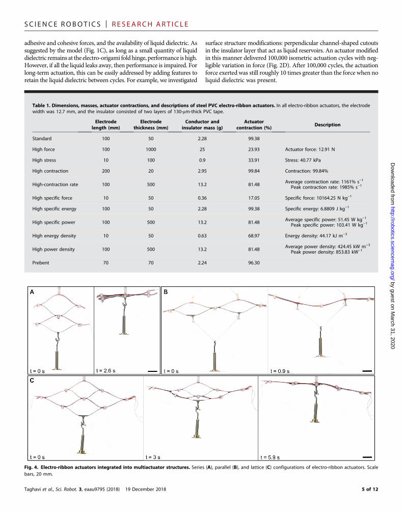
Fig. 4. Electro-ribbon actuators integrated into multiactuator structures. Series (A), parallel (B), and lattice (C) configurations of electro-ribbon actuators. Scalebars, 20 mm.
Table 1. Dimensions, masses, actuator contractions, and descriptions of steel PVC electro-ribbon actuators. In all electro-ribbon actuators, the electrodewidth was 12.7 mm, and the insulator consisted of two layers of 130-mm-thick PVC tape.
Electrodelength (mm)
Electrodethickness (mm)
Conductor andinsulator mass (g)
Actuatorcontraction (%)
Description
Standard
100 50 2.28 99.38High force
100 1000 25 23.93 Actuator force: 12.91 NHigh stress
10 100 0.9 33.91 Stress: 40.77 kPaHigh contraction
200 20 2.95 99.84 Contraction: 99.84%High-contraction rate
100 500 13.2 81.48 Average contraction rate: 1161% s−1Peak contraction rate: 1985% s−1
High specific force
10 50 0.36 17.05 Specific force: 10164.25 N kg−1High specific energy
100 50 2.28 99.38 Specific energy: 6.8809 J kg−1High specific power
100 500 13.2 81.48 Average specific power: 51.45 W kg−1Peak specific power: 103.41 W kg−1
High energy density
10 50 0.63 68.97 Energy density: 44.17 kJ m−3High power density
100 500 13.2 81.48 Average power density: 424.45 kW m−3Peak power density: 853.83 kW−1
Prebent
70 70 2.24 96.305 of 12
SC I ENCE ROBOT I C S | R E S EARCH ART I C L E
by guest on March 31, 2020
http://robotics.sciencemag.org/
Dow
nloaded from
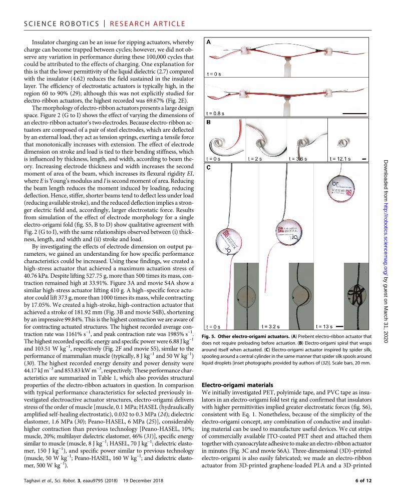
Insulator charging can be an issue for zipping actuators, wherebycharge can become trapped between cycles; however, we did not ob-serve any variation in performance during these 100,000 cycles thatcould be attributed to the effects of charging. One explanation forthis is that the lower permittivity of the liquid dielectric (2.7) comparedwith the insulator (4.62) reduces the field sustained in the insulatorlayer. The efficiency of electrostatic actuators is typically high, in theregion 60 to 90% (29); although this was not explicitly studied forelectro-ribbon actuators, the highest recorded was 69.67% (Fig. 2E).
Themorphology of electro-ribbon actuators presents a large designspace. Figure 2 (G to I) shows the effect of varying the dimensions ofan electro-ribbon actuator’s two electrodes. Because electro-ribbon ac-tuators are composed of a pair of steel electrodes, which are deflectedby an external load, they act as tension springs, exerting a tensile forcethat monotonically increases with extension. The effect of electrodedimension on stroke and load is tied to their bending stiffness, whichis influenced by thickness, length, and width, according to beam the-ory. Increasing electrode thickness and width increases the secondmoment of area of the beam, which increases its flexural rigidity EI,whereE is Young’smodulus and I is secondmoment of area. Reducingthe beam length reduces the moment induced by loading, reducingdeflection. Hence, stiffer, shorter beams tend to deflect less under load(reducing available stroke), and the reduced deflection implies a stron-ger electric field and, accordingly, larger electrostatic force. Resultsfrom simulation of the effect of electrode morphology for a singleelectro-origami fold (fig. S5, B to D) show qualitative agreement withFig. 2 (G to I), with the same relationships observed between (i) thick-ness, length, and width and (ii) stroke and load.
By investigating the effects of electrode dimension on output pa-rameters, we gained an understanding for how specific performancecharacteristics could be increased. Using these findings, we created ahigh-stress actuator that achieved a maximum actuation stress of40.76 kPa. Despite lifting 527.75 g, more than 500 times its mass, con-traction remained high at 33.91%. Figure 3A and movie S4A show asimilar high-stress actuator lifting 410 g. A high–specific force actu-ator could lift 373 g,more than 1000 times itsmass, while contractingby 17.05%. We created a high-stroke, high-contraction actuator thatachieved a stroke of 181.92 mm (Fig. 3B and movie S4B), shorteningby an impressive 99.84%. This is the highest contractionwe are aware offor contracting actuated structures. The highest recorded average con-traction rate was 1161% s−1, and peak contraction rate was 1985% s−1.The highest recorded specific energy and specific powerwere 6.88 J kg−1
and 103.51 W kg−1, respectively (Fig. 2F and movie S5), similar to theperformance of mammalian muscle (typically, 8 J kg−1 and 50W kg−1)(30). The highest recorded energy density and power density were44.17 kJm−3 and 853.83 kWm−3, respectively. These performance char-acteristics are summarized in Table 1, which also provides structuralproperties of the electro-ribbon actuators in question. In comparisonwith typical performance characteristics for selected previously in-vestigated electroactive actuator structures, electro-origami deliversstress of the order ofmuscle [muscle, 0.1MPa; HASEL (hydraulicallyamplified self-healing electrostatic), 0.032 to 0.3 MPa (24); dielectricelastomer, 1.6 MPa (30); Peano-HASEL, 6 MPa (25)], considerablyhigher contraction than previous technology [Peano-HASEL, 10%;muscle, 20%; multilayer dielectric elastomer, 46% (31)], specific energysimilar to muscle (muscle, 8 J kg−1; HASEL, 70 J kg−1; dielectric elasto-mer, 150 J kg−1), and specific power similar to previous technology(muscle, 50 W kg−1; Peano-HASEL, 160 W kg−1; and dielectric elasto-mer, 500 W kg−1).
Taghavi et al., Sci. Robot. 3, eaau9795 (2018) 19 December 2018
Electro-origami materialsWe initially investigated PET, polyimide tape, and PVC tape as insu-lators in an electro-origami fold test rig and confirmed that insulatorswith higher permittivities implied greater electrostatic forces (fig. S6),consistent with Eq. 1. Nonetheless, because of the simplicity of theelectro-origami concept, any combination of conductive and insulat-ing material can be used to manufacture useful devices. We cut stripsof commercially available ITO-coated PET sheet and attached themtogetherwith cyanoacrylate adhesive tomake an electro-ribbon actuatorin minutes (Fig. 3C and movie S6A). Three-dimensional (3D)–printedelectro-origami is also easily fabricated; we made an electro-ribbonactuator from 3D-printed graphene-loaded PLA and a 3D-printed
Fig. 5. Other electro-origami actuators. (A) Prebent electro-ribbon actuator thatdoes not require preloading before actuation. (B) Electro-origami spiral that wrapsaround itself when actuated. (C) Electro-origami actuator inspired by spider silk,spooling around a central cylinder in the samemanner that spider silk spools aroundliquid droplets [inset photographs provided by authors of (32)]. Scale bars, 20 mm.
6 of 12
SC I ENCE ROBOT I C S | R E S EARCH ART I C L E
by guest on March 31, 2020
http://robotics.sciencemag.org/
Dow
nloaded from
pure PLA insulator (Fig. 3Dandmovie S6B). The insulatorwas a single0.4-mm-thick 3D-printed layer of standard PLA filament that, oncesoaked in liquid dielectric, could withstand 10 kV. It is even possibleto manufacture electro-origami devices with household or officematerials. We used a normal (HB grade) pencil to draw graphite elec-trodes onto standard photocopier paper and joined the two layerstogether with cyanoacrylate adhesive to make a pencil-paper electro-ribbon actuator. After soaking in silicone oil, the 2-g paper actuatorcould lift 3 g through a stroke of 45 mm (Fig. 3E and movie S6C).
Electro-origami structuresElectro-ribbon actuators can also be easily integrated within multi-actuator structures to deliver higher forces and strokes. Stroke canbe improved by stacking multiple actuators in series (Fig. 4A andmovie S7A), and force can be increased by using a parallel arrange-ment (Fig. 4B and movie S7B). A lattice containing both series andparallel actuator elements allows for a balance between improvedstroke and force (Fig. 4C and movie S7C). Bulk repetition of latticestructures will allow for themanufacture of self-actuatingmetamaterialspowered by electro-origami across multiple scales.
Although the structures presented so far require external load toprime them for actuation, it is straightforward to manufacture prebentelectro-ribbon actuators that do not require preloading (Fig. 5A andmovie S8A). The electro-origami concept can be further extended toa wide range of electro-origami actuators. Figure 5B shows anelectro-origami spiral, which consists of two insulated electrodeswrapped around an acrylic cylinder. When actuated, they wrap aroundone another, creating a tightly bound spiral of alternating electrodes
Taghavi et al., Sci. Robot. 3, eaau9795 (2018) 19 December 2018
(movie S8B). This arrangement can be used to make simple torsionalactuators. An alternative arrangement of this structure takes inspirationfrom the tension-maintaining behavior of spider silk: We made anelectro-origami spiral constrained at one electrode tip that spoolsaround a central cylinder in the same manner that spider silk spoolsaround liquid droplets (32), resulting in a large stroke of more than60 cm (Fig. 5C and movie S8C). The maximum stroke of this designis only limited by electrode length.
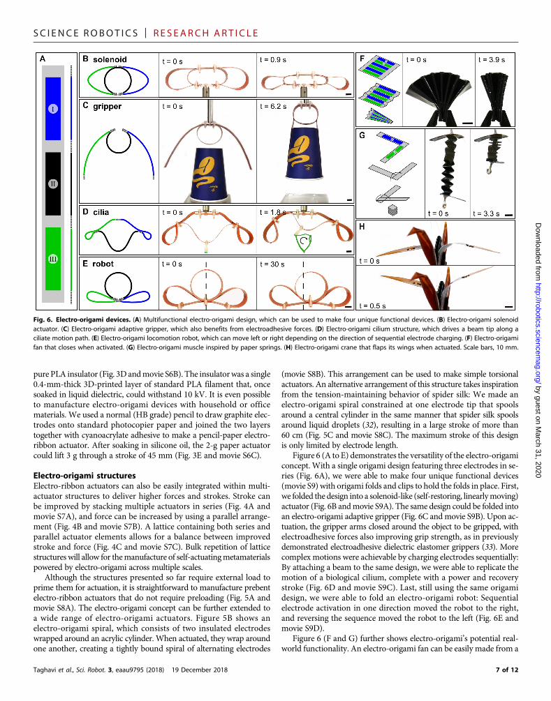
Figure 6 (A to E) demonstrates the versatility of the electro-origamiconcept. With a single origami design featuring three electrodes in se-ries (Fig. 6A), we were able to make four unique functional devices(movie S9) with origami folds and clips to hold the folds in place. First,we folded the design into a solenoid-like (self-restoring, linearlymoving)actuator (Fig. 6B andmovie S9A). The same design could be folded intoan electro-origami adaptive gripper (Fig. 6C andmovie S9B). Upon ac-tuation, the gripper arms closed around the object to be gripped, withelectroadhesive forces also improving grip strength, as in previouslydemonstrated electroadhesive dielectric elastomer grippers (33). Morecomplex motions were achievable by charging electrodes sequentially:By attaching a beam to the same design, we were able to replicate themotion of a biological cilium, complete with a power and recoverystroke (Fig. 6D and movie S9C). Last, still using the same origamidesign, we were able to fold an electro-origami robot: Sequentialelectrode activation in one direction moved the robot to the right,and reversing the sequence moved the robot to the left (Fig. 6E andmovie S9D).
Figure 6 (F and G) further shows electro-origami’s potential real-world functionality. An electro-origami fan can be easily made from a
Fig. 6. Electro-origami devices. (A) Multifunctional electro-origami design, which can be used to make four unique functional devices. (B) Electro-origami solenoidactuator. (C) Electro-origami adaptive gripper, which also benefits from electroadhesive forces. (D) Electro-origami cilium structure, which drives a beam tip along aciliate motion path. (E) Electro-origami locomotion robot, which can move left or right depending on the direction of sequential electrode charging. (F) Electro-origamifan that closes when activated. (G) Electro-origami muscle inspired by paper springs. (H) Electro-origami crane that flaps its wings when actuated. Scale bars, 10 mm.
7 of 12
SC I ENCE ROBOT I C S | R E S EARCH ART I C L E
Dow
n
flat rectangular sheet with alternating electrodes. Alternating mountainand valley folds transform the sheet into a concertina shape, whichmaybe pinched one end to produce a fan that closes when activated (Fig. 6Fandmovie S10A). This design could be used to create self-packing solarpanels for space applications, with origami folding allowing compactpacking as is achieved by tree leaves when packed inside buds (34). Fig-ure 6G shows an electro-origami muscle made by alternately foldingtwo insulated electrodes over one another. This artificial muscle exhib-itedmore than 50% contraction (movie S10B), shortening bymore than4 cm in less than a second. Electro-origami artificial muscles could beused to replace or augment biologicalmuscle in humanoid robots, pros-thetics, and wearable devices.
Last, an origami crane was fabricated from polyimide film andpainted with conducting ink electrodes on its wings and inside itsbody. Activation causes wing flexion resulting in a flapping motion(Fig. 6H and movie S10C). Combined with printable conductive inks,the electro-origami concept will allow inkjet-printed origami patternsthat can be folded into functional devices.
by guest on Marc
http://robotics.sciencemag.org/
loaded from
DISCUSSIONElectro-origami is an actuation concept that exploits electrostatic at-traction, high-permittivity, high–breakdown strength insulating fluidsand dielectrophoresis to deliver powerful, versatile actuators and roboticdevices. Although the number of active designs that electro-origamienables is very large, it is limited by the progressive zipping natureof the electro-origami concept—active devices that lack an origamifold to initiate zipping cannot be directly actuated. For these devices,discrete electro-origami actuators could be included to achievemotion.Another limitation of electro-origami is the high voltage required todevelop strong electric fields. As with other state-of-the-art high-fieldactuators (24, 25, 30), an amplifier is needed to supply high voltage,whichmay introduce safety concerns for some applications.Nonetheless,the performance and versatility demonstrated here highlight the suitabil-ity of the electro-origami concept for a wide range of fields—includingrobotics, engineering, and transportation—and for applications such asdeployable structures, space systems, and multiple degrees-of-freedomprostheses and robots.
h 31, 2020
MATERIALS AND METHODSManufacture of electro-origami foldsFigure S1A shows one way of making an electro-origami fold:
1) The electrodes and insulator are prepared.Wires can be solderedto the electrodes so that voltage can be applied. The insulator shouldbe larger than the electrodes in the nonthickness directions to fullyencapsulate it.
2) The electrodes are insulated with an insulator material, whichalso serves as the origami material to be folded. The figure showsinsulation of the electrodes on both sides. In this case, the tape fullyencapsulated the electrode to ensure that no arcing occurred. It ispossible to insulate on the inner surface of the origami fold only;however, in this case, the insulation should be especially large in thenonthickness directions to prevent arcing.
3) The electro-origami is folded to prepare it for actuation.
Full submersion experimentAs part of the electro-origami concept, a small bead of liquid dielectric
is added at the origami hinge, which considerably increases electro-Taghavi et al., Sci. Robot. 3, eaau9795 (2018) 19 December 2018
static force due to its higher breakdown strength and permittivity.A similar increase in tensile force could be achieved by submergingthe whole device in liquid dielectric, but this would considerably in-crease mass and slow down movement because of opposing viscousand hydraulic forces. The liquid bead, in contrast, negligibly altersdevice mass and behavior but greatly increases force. We comparedthe difference in isometric tensile force between a fully submergedelectro-ribbon actuator and one with only a bead of liquid dielectricat each origami hinge. The nonsubmerged actuator delivered 91.61%of the force of the submerged actuator, confirming the effectivenessof the electro-origami concept.
Electro-origami field strength distributionThe field strength distribution of electro-ribbon actuators is highlyconcentrated near the origami hinge. Figure S1B shows resultsfrom simulation using a field modeling software (QuickField, TeraAnalysis Ltd., Denmark). The conductors are 30 mm in length, andthe actuator is submerged in a medium with permittivity of 2.7,matching the silicone oil used in most experiments. The PVC tapepermittivity is 4.62. The voltage between the upper and lower elec-trodes is 10 kV.
Derivation of electrostatic attractive force between twoplates separated by an insulator and a mediumIn electro-origami, an electrode and counterelectrode form a zippingstructure. Between the electrodes are an insulator (which preventsshort circuit) and a medium (which may be air or high-permittivityliquid dielectric). To shed light on the behavior of this system, weperformed from-first-principles electrical analysis on an analogoussystem.
Consider two plates separated by two dielectric slabs of thicknessestinsulator and tmedium and permittivities einsulator and emedium (fig. S2A).They may be modeled as two variable capacitors in series whosecapacitances are Cinsulator and Cmedium. When a voltage V is appliedacross the two plates, they become charged. A virtual, infinitely thinplate at a voltage Vinterface may be assumed between the two di-electric slabs, where Vinterface is greater than zero but lower thanV. The charge separated across the insulator dielectric slab,Qinsulator,is described by
Qinsulator ¼ CinsulatorV interface ð4Þ
The charge separated across the medium dielectric slab, Qmedium,is described by
Qmedium ¼ CmediumðV � V interfaceÞ ð5Þ
Because the slabs are modeled as two capacitors in series, theircharges are equivalent
Qinsulator ¼ Qmedium ð6Þ
∴CinsulatorV interface ¼ CmediumðV � V interfaceÞ ð7Þ
∴V interface ¼ Cmedium
Cinsulator þ CmediumV ð8Þ
8 of 12
SC I ENCE ROBOT I C S | R E S EARCH ART I C L E
by guest on March 31, 2020
http://robotics.sciencemag.org/
Dow
nloaded from
The capacitance of the insulator and medium dielectric slabs isdescribed by
Cinsulator ¼ einsulatore0Atinsulator
ð9Þ
and
Cmedium ¼ emediume0Atmedium
ð10Þ
respectively. Substituting these into Eq. 8 leads to
V interface ¼ emediumtinsulatoreinsulatortmedium þ emediumtinsulator
V ð11Þ
The energy Einsulator stored across in insulator slab is given by
Einsulator ¼ 12einsulatore0AV interface
2
tinsulatorð12Þ
Differentiation of Einsulator with respect to tinsulator gives the forceFinsulator exerted at the interface.
Finsulator ¼ � 12einsulatore0AV interface
2
tinsulator2ð13Þ
Substituting Eq. 11 results in
Finsulator ¼ � 12
einsulatore0AV2
einsulatoremedium
tmedium þ tinsulator� �2 ð14Þ
An equal and opposite force is felt by the lower plate. Similarly,for the medium slab, the force Fmedium exerted at the interface is
Fmedium ¼ 12emediume0AðV � V interfaceÞ2
tmedium2 ð15Þ
Substituting Eq. 11 results in
Fmedium ¼ 12
emediume0AV2
emediumeinsulator
tinsulator þ tmedium
� �2 ð16Þ
Unless the insulator and medium have the same permittivity, theforces exerted at the plates differ: The plate beside thematerial with thelower permittivity will experience a greater force. However, this doesnot imply that a net force acts to move the system through space; theresultant force acting on the plates ismatched by an equal and oppositeresultant force acting on the interface between the two dielectric slabs
Finterface ¼ Finsulator þ Fmedium
¼ 12emediumeinsulatorðeinsulator � emediumÞe0AV2
ðeinsulatortmedium þ emediumtinsulatorÞ2ð17Þ
Taghavi et al., Sci. Robot. 3, eaau9795 (2018) 19 December 2018
In the case of electro-origami, the insulator is solid and firmlyattached by adhesive to the insulator-adjacent plate, while themediumis liquid. Hence, we assume that the insulator and insulator-adjacentplate are inseparable and that the insulator is considerably stiffer thanthe (liquid) medium, such that its compression by Finsulator is negli-gible, and it transmits any forces felt directly to the insulator-adjacentplate. This implies that the medium force Fmedium will be exerted onboth plates. Hence, the attractive force between the two plates isequal to Fmedium
F ¼ 12
emediume0AV2
emediumeinsulator
tinsulator þ tmedium
� �2 ð18Þ
Experimental validation of droplet volume modelWe performed experiments to confirm the validity of the Euler-Bernoulli beam theory droplet volume model. An exact quantityof liquid dielectric was added by micropipette to an electro-origamifold hinge matching the one simulated by the model (fig. S1C). Ap-plied voltage was gradually increased until pull-in occurred, andthis pull-in voltage was recorded. Results show good agreementwith those of the model (Fig. 1C).
Manufacture of electro-ribbon actuatorsFigure 1F shows one way of making an electro-ribbon actuator:
1) The electrodes and insulator are prepared.Wires can be solderedto the electrodes so that voltage can be applied. The insulator shouldbe larger than the electrodes in the nonthickness directions to fullyencapsulate it.
2) One or both electrodes are insulatedwith the insulatormaterial.The figure shows insulation of the upper electrode on both sides. Inthis case, the tape fully encapsulates the electrode to ensure that noarcing will occur. It is also possible to insulate both electrodes. Al-ternatively, insulation can only consist of the central insulating layer;in this case, it should be especially large in the nonthickness directionsto prevent arcing around it.
3) Connections at the ends of the actuator are made to createtwo origami hinges and hold the actuator together under high load.Connections can be made using any connection method, such asadhesive, magnetic, or mechanical. During experiments, we used cya-noacrylate or epoxy adhesive, single magnets (because some electrodeswere magnetic), or magnet pairs or mechanical clips, including insu-lated bulldog clips or custom acrylic clips held in place by plastic nutsand bolts.
4) The actuator is complete and can be extended by application ofa central load. A liquid dielectric bead may be added at each origamihinge, and application of high voltage will cause exertion of force andcontraction.
Reported electro-ribbon actuatorsThroughout the main text, we avoid describing the specifications of ex-ample actuators in detail for reasons of brevity and instead refer to ex-ample actuators based on their qualities, for example, the “standard”and the “high-stress” electro-ribbon actuator. These actuators are madefromof steel strips insulatedwith PVC tape. The dimensions of the steelstrips used to fabricate them, along with their masses, contractions, anddescriptions, are shown in Table 1.
9 of 12
SC I ENCE ROBOT I C S | R E S EARCH ART I C L E
by guest on March 31, 2020
http://robotics.sciencemag.org/
Dow
nloaded from
Test protocol for isometric and isotonic experimentsDuring isometric testing, an electronic ribbon actuator was held atvarious actuator extensions (fig. S4C). The upper central point ofthe actuator was attached to a load cell (DBCR-10N-002-000, AppliedMeasurements Ltd., UK), which was attached to a rigid frame. Thelower central point of the actuator was attached to a precision jackstand, which could be used to adjust actuator extension. Extensionwas recorded with a laser displacement meter (LK-G402, Keyence,Japan), which measured the displacement of the top of the jack stand.Application of high voltage caused electrostatic attraction and zipping,resulting in a tensile force at the center of the actuator, which wasmeasured by the load cell. Liquid dielectric was added by pipette tothe actuator’s origami hinges.
During isotonic testing, the upper central point of the actuator wasattached to a rigid frame (fig. S4C). A knownmass was attached to thelower central point of the actuator, exerting a constant vertical loadand causing actuator extension. Actuator contraction was recordedwith a laser displacement meter, which measured the displacementof the test mass. For each trial, liquid dielectric was added by pipetteto the actuator’s origami hinges, and high voltage was applied untilactuation was completed.
Variation between samples of standardelectro-ribbon actuatorTo investigate variation between actuator samples, we fabricated fivestandard electro-ribbon actuators and performed isometric tests at ac-tuator extensions of 1, 2, and 4 mm. Figure S4 (D and E) shows tensileforce variation with voltage and extension: Points are averages of fivetrials of five samples (25 total trials), and error bars show ±1 SD be-tween averages of five trails for each sample (five samples). MaximumSD for liquid dielectric data was 0.2475 N at 6 kV.
Bandwidth testingWe performed bandwidth testing to determine the frequencies ofoperation that electro-origami could deliver. A standard electro-ribbonactuator (table S2) was modified by the addition of a small mechanicalstop. This stop slightly reduced the maximum contraction but limitedthe adhesive and cohesive forces associated with the liquid dielectricwhen the actuator fully closed, allowing for higher-frequency repeatingoperation. At a voltage of 7 kV, this actuator was capable of full actua-tion and relaxation at a bandwidth of 0.125Hz. If full contraction is notrequired, such that lower stroke is allowed, and bandwidth is less in-fluenced by adhesive and cohesive forces, then much higher band-widths can be achieved; 5 and 10 Hz are demonstrated using 7 kV (Fig.2C and movie S3).
Cyclic testingCyclic testing was performed to determine the effects of long-termcontinuous reciprocating use of electro-origami devices. A 30-mm-long, 12.7-mm-wide electro-ribbon actuator with 50-mm-thick elec-trodes was modified with multiple parallel channel-shaped cutoutsin the insulator layer, aligned perpendicularly to actuator’s long axis,which acted as liquid reservoirs to retain liquid dielectric during thecyclic experiment. The actuator was stimulated with a 50% duty cyclesquare voltage wave of amplitude 8 kV at a frequency of 4 Hz. Therewas negligible variation in isometric force over 100,000 cycles (Fig. 2D),and after 100,000 cycles, the force exerted was 8.706 times greater thanthe force exerted by the same actuatorwith no liquid dielectric present.This demonstrates how features such as surface structure modifications
Taghavi et al., Sci. Robot. 3, eaau9795 (2018) 19 December 2018
can be used to ensure retention of liquid dielectric for long-termoperation of electro-origami devices. Surface structure (includingsurface roughness) can affect the behavior of the liquid dielectric andthe electric field generated and thus the behavior of electro-origamidevices.
Measurement of energetic efficiencyTo measure energy efficiency, we used data recorded from experi-ments. The high-voltage amplifiers (5HVA24-BP1, UltraVolt,USA) provided monitor voltage outputs corresponding to deliveredhigh voltage and current. Thesemonitor voltages were recorded witha data acquisition device (NIUSB-6343, National Instruments, USA)and converted to units of volts and amperes. The product of theinferred voltage and current was the electrical power. To determineelectrical energy consumed, we numerically integrated electricalpower with the MATLAB “trapz” function as an actuator lifted aload. Because the voltage when the actuator was relaxing was zero,the power was also zero at this time, and only the electrical powerwhen the actuator was shortening was considered. Mechanicalenergy output was calculated according to gravitational potentialenergy, i.e., GPE =mgh, where GPE is gravitational potential energy,m is mass, g is local acceleration due to gravity, and h is stroke. Ef-ficiency was calculated as mechanical energy output divided by elec-trical energy consumed.
Efficiency varied between experiments, and the greatest variationwas a function of which insulation was used. For example, PVC tape,which has a comparatively low resistivity (1012 to 1014 ohm·m), re-sulted in a noticeable leakage current, which consumed electricalenergy without providing any mechanical energy, resulting in lowerefficiencies. With PVC insulation, maximum leakage current when6 kV was applied was 21.74 mA, implying a leakage current perunit area of 17.12 mA m−2 (electrode dimensions were 100 mm by12.7 mm). In contrast, in experiments where polyimide tape wasused (resistivity on the order of 1015 ohm·m), maximum leakage cur-rent was around 0.2 mA, implying a leakage current per unit area of0.16 mA m−2. Hence, less energy was lost to leakage, and efficiencywas considerably higher. The trial with the greatest efficiency in-volved a standard electro-origami actuator, insulated with two layersof polyimide tape, lifting a 3 g mass while actuated by an appliedvoltage of 6 kV. The stroke was 51.7 mm, implying an output me-chanical energy of 1.5215 mJ. The consumed electrical energy calcu-lated with the MATLAB trapz function was 2.1839 mJ. Therefore, theefficiency was calculated as 69.67%. Figure 2E shows applied voltage,delivered current, and electrical power traces during the experimentin question.
Simulating the effect of morphology on output parameterEuler-Bernoulli beam theory becomes less accurate as deflections in-crease. The developed MATLAB model can be used with larger tiploads that induce greater deflections; however, the diminishing accu-racy of results as tip load increases should be considered. Nonetheless,results can provide qualitative support for experimental findings. Thedevelopedmodel was used to investigate the effect ofmorphology (elec-trode thickness, length, and width) on output parameters (maximumload lifted and maximum stroke) for comparison with experimentalresults (Fig. 2, G to I). The simulated electrode had the following stan-dard properties: thickness, 50 mm; length, 100mm;width, 12.7mm; andYoung’s modulus, 190 GPa (matching those of the standard electro-ribbon actuator).
10 of 12
SC I ENCE ROBOT I C S | R E S EARCH ART I C L E
by guest on March 31, 2020
http://robotics.sciencemag.org/
Dow
nloaded from
Calculation of performance characteristics forelectro-ribbon actuatorsActuator thicknesswas calculated assuming two electrodes (using steelstrip thickness) and one insulator, the insulator being composed oftwo layers of PVC tape. This was the number of layers used to makemost actuators (the insulator could have been composed of a singlelayer of PVC tape butwould not be able towithstand 10 kV). Similarly,actuatormasswas the combinedmass of the conductors and insulator.Detailed characteristics of the electro-ribbon actuators in question areavailable in Table 1.
Actuator force was determined differently depending on the typeof experiment. For isotonic experiments, actuator force was the weightof the load lifted. For isometric experiments, actuator force was re-corded using a load cell (DBCR-10N-002-000, AppliedMeasurementsLtd., UK). Maximum achieved actuator force was 12.91 N using thehigh-force actuator, which lifted 1.316 kg.
Stress was calculated as actuator force divided by maximum actu-ator cross-sectional area, which was steel strip free length multipliedby steel strip width. The highest achieved stress was achieved with anactuator 10 mm in length and 12.7 mm in width, implying a maxi-mum cross-sectional area of 127 mm2. This actuator lifted a maxi-mum load of 527.75 g, implying a force of 5.1772 N. These imply astress of 40.77 kPa.
Specific force was calculated as actuator force divided by actuatormass. The highest achieved specific force was 10164.25 N kg−1 withthe high–specific force actuator, which lifted 373 g despite having amass of only 0.36 g, lifting more than 1036 times its own mass.
Stroke was the distance traveled during actuation, typically re-corded using a laser displacement meter (LK-G402, Keyence, Japan).Contraction was calculated as stroke divided by initial actuator length,which was equal to stroke divided by the sum of stroke and actuatorthickness. The highest achieved contraction was achieved by an actu-ator featuring 20-mm-thick electrodes, implying an actuator thicknessof 300 mm (two 20-mm-thick electrodes and two 130-mm-thick insu-lator layers). The stroke was 181.92 mm, implying an initial actuatorlength of 182.22 mm. This implied a contraction of 99.84%.
Contraction rate was calculated as actuator speed divided by initialactuator length. The highest recorded contraction rates were achievedduring power measurement experiments (Fig. 2F and movie S5). Asthe mass traveled upward, it traveled 5.0869 mm in 0.073 s, implyingan average speed of 69.6835mm s−1. The actuator’s initial length was6mm, implying an average contraction rate of 1161% s−1. The actuator’speak speed as themass traveled upwardwas 119.1121mm s−1, implyinga peak contraction rate of 1985% s−1.
Stroke mechanical energy was calculated as the change in grav-itational potential energy associated with stroke, equal to the prod-uct of mass, stroke, and local gravitational acceleration. Power wascalculated as the sum of the time derivatives of potential energy andkinetic energy. The time derivative of potential energy was calculatedas d
dt ðmghÞ ¼ mgv, wheremwasmass, gwas local acceleration due togravity, h was mass position, and v was mass velocity. The time de-rivative of kinetic energy was calculated as d
dt12mv2Þ ¼�
mva, where awas mass acceleration. Hence, power was calculated as mgv + mga.
Specific energy was calculated as stroke mechanical energy dividedby actuator mass, and specific power was calculated as power dividedby actuatormass. The highest recorded specific energywas achieved byan actuator ofmass 2.28 g, which lifted a 27.75-g load through a strokeof 57.63 mm, implying a stroke mechanical energy of 15.6885 mJ,which implies a specific energy of 6.8809 J kg−1. The highest recorded
Taghavi et al., Sci. Robot. 3, eaau9795 (2018) 19 December 2018
specific power was achieved by an actuator of mass 13.2 g, which oscil-lated a 1033-gmass at a frequency of 6.9Hz (Fig. 2F andmovie S5). Theaverage and peak powers were 0.6792 and 1.3663W, implying averageand peak specific powers of 51.45 and 103.51 W kg−1, respectively.
Energy density was calculated as stroke mechanical energy dividedby actuator volume. Power density was calculated as power divided byactuator volume. The highest recorded energy density was achievedwith an actuator 10 mm in length and 12.7 mm in width, featuringtwo 50-mm-thick electrodes and two layers of 130-mm-thick insula-tor, implying a volume of 45.72 mm3. This actuator lifted a 257.3-gload through a stroke of 0.8 mm, implying a stroke mechanical en-ergy of 2.0193 mJ, which implies an energy density of 44.17 kJ m−3.The highest power density was achieved by the same actuator withthe highest recorded specific power, which was 100 mm in length and12.7 mm in width, and featured two 500-mm-thick electrodes and twolayers of 130-mm-thick insulator, implying a volume of 1600.2 mm3.The average and peak powers were 0.6792 and 1.3663 W, implyingaverage and peak power densities of 424.45 and 853.83 kW m−3,respectively.
The dimensions, masses, and contractions of actuators achievingmaximum performance characteristics are presented in Table 1. Ingeneral, long actuators with thin electrodes were more compliantand deflected further under load, implying high strokes. In contrast,short actuators with thick electrodes were stiffer and deflected less un-der load, implying increased electric fields and consequently greaterforces. To maximize actuation stress, short actuators were also advan-tageous because they maximized the amount of “active” actuator area;in long actuators that progressively zip, only a small fraction of the ac-tuator area is contributing a large electrostatic force. For performancemetrics that are a function of both force and stroke, such as specificenergy and power density, intermediate values of actuator lengthand thickness resulted in the best performance.
Insulator material investigation using an electro-origamifold test rigWe investigated the electro-origami concept using a simple test rig(fig. S1C). The test rig consisted of an upper electrode (a 70-mm-thick,12.7-mm-wide steel strip) thatwas attachedwith adhesive to an acrylicplate. The upper electrode was insulated with one of several insulatormaterials. A second electrode (a 70-mm-thick, 12.7-mm-wide steelstrip with free length of 100 mm) was fixed at one end adjacent tothe insulated electrode. Application of a test mass to the tip of the sec-ond electrode caused cantilever deflection. Application of a bead ofliquid dielectric and high voltage caused electrostatic zipping, raisingthe test mass against gravity.
We investigated the maximum load lifted, with the insulator beingPET, polyimide tape, or PVC tape. The permittivity of PET is typicallystated as between 3 and 3.4, that of polyimide tape as between 3.4 and3.5, and that of PVC tape used as 4.62 (personal communication, Ad-vance Tapes). The thickness of the insulator layer was conserved, andthe dominant contributor to flexural rigidity was the steel electrode, sothe behavior was purely a function of electrical properties. Resultsshowed that maximum load lifted increasedmonotonically with insu-lator permittivity (fig. S6, C and D), as predicted by eq. S14.
Multiactuator structuresThe standard electro-ribbon actuator could lift a 26-g mass through astroke of 57.63 mm. Two standard electro-ribbon actuators in seriescould lift a 22-g mass through a stroke of 109.90 mm. Two standard
11 of 12
SC I ENCE ROBOT I C S | R E S EARCH ART I C L E
electro-ribbon actuators in parallel could lift a 38-g mass through astroke of 67.42 mm. The lattice of standard electro-ribbon actuatorscould lift a 26-g mass through a stroke of 107.24 mm.
Dow
nloaded from
SUPPLEMENTARY MATERIALSrobotics.sciencemag.org/cgi/content/full/3/25/eaau9795/DC1Materials and MethodsFig. S1. Manufacture, field strength distribution, and experimental test setup of electro-origamifold.Fig. S2. Models used to derive electrostatic force.Fig. S3. Flowchart showing structure of a recursive MATLAB script.Fig. S4. Characterization and analysis of electro-ribbon actuator.Fig. S5. Results from electro-origami fold simulation.Fig. S6. Effect of material properties on performance of electro-origami fold.Table S1. Summary of materials used for electro-origami.Movie S1. An electro-origami fold.Movie S2. Isotonic and isometric actuation of a standard electro-ribbon actuator.Movie S3. Bandwidth testing of a standard electro-ribbon actuator.Movie S4. High-stress and high-contraction electro-ribbon actuators.Movie S5. High-power electro-ribbon actuator.Movie S6. Manufacture and testing of electro-ribbon actuators made from different materials.Movie S7. Series, parallel, and lattice arrangements of standard electro-ribbon actuators.Movie S8. Electro-origami actuators.Movie S9. Four electro-origami devices from one electro-origami design.Movie S10. Complex electro-origami devices.
by guest on March 31, 2020
http://robotics.sciencemag.org/
REFERENCES AND NOTES1. P. W. K. Rothemund, Folding DNA to create nanoscale shapes and patterns. Nature 440,
297–302 (2006).2. H. Liu, R. M. Crooks, Three-dimensional paper microfluidic devices assembled using the
principles of origami. J. Am. Chem. Soc. 133, 17564–17566 (2011).3. Z. Song, T. Ma, R. Tang, Q. Cheng, X. Wang, D. Krishnaraju, R. Panat, C. K. Chan, H. Yu,
H. Jiang, Origami lithium-ion batteries. Nat. Commun. 5, 3140 (2014).4. A. M. Hoover, R. S. Fearing, Fast scale prototyping for folded millirobots, in 2008 IEEE
International Conference on Robotics and Automation, Pasadena, CA, USA, 19 to 23 May 2008(IEEE, 2008), pp. 1777–1778.
5. K. Miura, Map fold a la Miura style, its physical characteristics and application to thespace science, in Research of Pattern Formation (KTK Scientific Publishers, 1994),pp. 77–90.
6. K. Kuribayashi, K. Tsuchiya, Z. You, D. Tomus, M. Umemoto, T. Ito, M. Sasaki, Self-deployable origami stent grafts as a biomedical application of Ni-rich TiNi shape memoryalloy foil. Mater. Sci. Eng. A 419, 131–137 (2006).
7. R. V. Martinez, C. R. Fish, X. Chen, G. M. Whitesides, Elastomeric origami: Programmablepaper-elastomer composites as pneumatic actuators. Adv. Funct. Mater. 22, 1376–1384(2012).
8. S. Li, D. M. Vogt, D. Rus, R. J. Wood, Fluid-driven origami-inspired artificial muscles.Proc. Natl. Acad. Sci. U.S.A. 114, 13132–13137 (2017).
9. J. K. Paik, B. An, D. Rus, R. J. Wood, Robotic origamis: Self-morphing modular robots, inProceedings of the 2nd International Conference on Morphological Computation, Venice,12 to 14 September 2011 (ICMC, 2011), pp. 29–31.
10. S. M. Felton, M. T. Tolley, B. Shin, C. D. Onal, E. D. Demaine, D. Rus, R. J. Wood, Self-foldingwith shape memory composites. Soft Matter 9, 7688–7694 (2013).
11. E. Smela, O. Inganäs, I. Lundström, Controlled folding of micrometer-size structures.Science 268, 1735–1738 (1995).
12. D. Pugal, K. Jung, A. Aabloo, K. J. Kim, Ionic polymer–metal composite mechanoelectricaltransduction: Review and perspectives. Polym. Int. 59, 279–289 (2010).
13. R. P. Feynman, R. B. Leighton, M. Sands, The Feynman Lectures on Physics, Vol. II: MainlyElectromagnetism and Matter (Addison-Wesley, 1979).
14. W. C. Tang, T.-C. H. Nguyen, R. T. Howe, Laterally driven polysilicon resonantmicrostructures. Sens. Actuators 20, 25–32 (1989).
15. H. Conrad, H. Schenk, B. Kaiser, S. Langa, M. Gaudet, K. Schimmanz, M. Stolz, M. Lenz,A small-gap electrostatic micro-actuator for large deflections. Nat. Commun. 6, 10078(2015).
16. K. Sato, M. Shikida, Electrostatic film actuator with a large vertical displacement, in [1992]Proceedings IEEE Micro Electro Mechanical Systems, Travemunde, Germany, Germany,4 to 7 February 1992 (IEEE, 1992), pp. 1–5.
17. J. Branebjerg, P. A. Gravesen, A new electrostatic actuator providing improved strokelength and force, in [1992] Proceedings IEEE Micro Electro Mechanical Systems,Travemunde, Germany, 4 to 7 February 1992 (IEEE, 1992), pp. 6–11.
Taghavi et al., Sci. Robot. 3, eaau9795 (2018) 19 December 2018
18. M. Elwenspoek, L. Smith, B. Hok, Active joints for microrobot limbs. J. Micromech. Microeng. 2,221–223 (1992).
19. L. Maffli, S. Rosset, H. R. Shea, Zipping dielectric elastomer actuators: Characterization,design and modeling. Smart Mater. Struct. 22, 104013 (2013).
20. A. S. Chen, H. Zhu, Y. Li, L. Hu, S. Bergbreiter, A paper-based electrostaticzipper actuator for printable robots, in 2014 IEEE International Conference on Roboticsand Automation (ICRA), Hong Kong, China, 31 May to 7 June 2014 (ICRA, 2014),pp. 5038–5043.
21. J. Li, H. Godaba, Z. Q. Zhang, C. C. Foo, J. Zhu, A soft active origami robot.Extreme Mechanics Letters 24, 30–37 (2018).
22. K. Sarabandi, L. Pierce, An overview of research in advanced microelectronics formicro-autonomous platforms, in Proceedings of SPIE—The International Societyfor Optical Engineering, Orlando, Florida, United States, 13 to 17 April 2009 (SPIE, 2009),pp. 73180M.
23. M. Gaudet, S. Uhlig, M. Stolz, S. Arscott, H. Conrad, S. Langa, B. Kaiser, H. Schenk,Electrostatic bending actuators with a liquid filled nanometer scale gap,in 2017 IEEE 30th International Conference on Micro Electro Mechanical Systems (MEMS),Vegas, Nevada, USA, 22 to 26 January 2017 (MEMS, 2017), pp. 175–178.
24. E. Acome, S. K. Mitchell, T. G. Morrissey, M. B. Emmett, C. Benjamin, M. King, M. Radakovitz,C. Keplinger, Hydraulically amplified self-healing electrostatic actuators with muscle-likeperformance. Science 359, 61–65 (2018).
25. N. Kellaris, V. Gopaluni Venkata, G. M. Smith, S. K. Mitchell, C. Keplinger, Peano-HASELactuators: Muscle-mimetic, electrohydraulic transducers that linearly contract onactivation. Sci. Robot. 3, eaar3276 (2018).
26. Z. Suo, Theory of dielectric elastomers. Acta Mech. Solida Sin. 23, 549–578 (2010).27. H. A. Pohl, The motion and precipitation of suspensoids in divergent electric fields.
J. Appl. Phys. 22, 869–871 (1951).28. H. Pellat, Électrostatique non fondée sur les lois de coulomb. Forces agissant sur les
diélectriques non électrisés. J. Phys. Theor. Appl. 5, 244–256 (1896).29. P. Brochu, Q. Pei, Advances in dielectric elastomers for actuators and artificial muscles.
Macromol. Rapid Commun. 31, 10–36 (2010).
30. J. D. W. Madden, N. A. Vandesteeg, P. A. Anquetil, P. G. A. Madden, A. Takshi, R. Z. Pytel,S. R. Lafontaine, P. A. Wieringa, I. W. Hunter, Artificial muscle technology: Physicalprinciples and naval prospects. IEEE J. Oceanic Eng. 29, 706–728 (2004).
31. G. Kovacs, L. Düring, S. Michel, G. Terrasi, Stacked dielectric elastomer actuator for tensileforce transmission. Sens. Actuators A Phys. 155, 299–307 (2009).
32. H. Elettro, S. Neukirch, F. Vollrath, A. Antkowiak, In-drop capillary spooling of spidercapture thread inspires hybrid fibers with mixed solid–liquid mechanical properties.Proc. Natl. Acad. Sci. U.S.A. 113, 6143–6147 (2016).
33. J. Shintake, S. Rosset, B. Schubert, D. Floreano, H. Shea, Versatile soft grippers withintrinsic electroadhesion based on multifunctional polymer actuators. Adv. Mater. 28,231–238 (2016).
34. H. Kobayashi, B. Kresling, J. F. V. Vincent, The geometry of unfolding tree leaves. Proc. Biol.Sci. 265, 147–154 (1998).
Acknowledgments: Funding: M.T. was supported by EPSRC grant EP/M026388/1 andEP/R02961X/1. T.H. was supported by EPSRC grant EP/M026388/1 and the Royal Academyof Engineering and the Office of the Chief Science Adviser for National Security underthe UK Intelligence Community Postdoctoral Fellowship Programme. J.R. was supported byEPSRC grants EP/L015293/1, EP/M020460/1, and EP/M026388/1 and the Royal Academyof Engineering through the Chair in Emerging Technologies scheme. Authorcontributions: M.T., T.H., and J.R. jointly conceived of electro-origami and all deviceconcepts. M.T. and T.H. designed the experiments, manufactured the devices, collectedthe data, performed the analysis, interpreted the results, wrote the manuscript, andcreated the movies. J.R. advised on all parts of the project and reviewed the manuscript.Competing interests: The authors declare that they have no competing interests.Two patent applications have been filed relating to this work by the University of Bristol:UK patent application no. GB1710400.1 on 29 June 2017 and international patentapplication no. PCT/GB2018/051799 on 29 June 2018. Data and materials availability: Alldata needed to evaluate the conclusions in the paper are present in the paper orthe Supplementary Materials. The datasets generated and analyzed during the currentstudy are available in the University of Bristol Research Data Repository (https://data.bris.ac.uk/data/): 10.5523/bris.1qreev788jlm82cvgytvm4cuoo. Requests for materials should beaddressed to J.R.
Submitted 2 August 2018Accepted 16 November 2018Published 19 December 201810.1126/scirobotics.aau9795
Citation: M. Taghavi, T. Helps, J. Rossiter, Electro-ribbon actuators and electro-origami robots.Sci. Robot. 3, eaau9795 (2018).
12 of 12

Electro-ribbon actuators and electro-origami robotsMajid Taghavi, Tim Helps and Jonathan Rossiter
DOI: 10.1126/scirobotics.aau9795, eaau9795.3Sci. Robotics
ARTICLE TOOLS http://robotics.sciencemag.org/content/3/25/eaau9795
MATERIALSSUPPLEMENTARY http://robotics.sciencemag.org/content/suppl/2018/12/17/3.25.eaau9795.DC1
REFERENCES
http://robotics.sciencemag.org/content/3/25/eaau9795#BIBLThis article cites 25 articles, 4 of which you can access for free
PERMISSIONS http://www.sciencemag.org/help/reprints-and-permissions
Terms of ServiceUse of this article is subject to the
is a registered trademark of AAAS.Science RoboticsNew York Avenue NW, Washington, DC 20005. The title (ISSN 2470-9476) is published by the American Association for the Advancement of Science, 1200Science Robotics
of Science. No claim to original U.S. Government WorksCopyright © 2018 The Authors, some rights reserved; exclusive licensee American Association for the Advancement
by guest on March 31, 2020
http://robotics.sciencemag.org/
Dow
nloaded from


![Electro-hydraulic actuators SKD32.. for valves SKD82 ...1].pdf · Electro-hydraulic actuators for valves with a 20 mm stroke SKD32.. SKD82.. ... In the manual operation mode the control](https://img.dokumen.tips/doc/110x75/5c60d8b009d3f28f6c8c3892/electro-hydraulic-actuators-skd32-for-valves-skd82-1pdf-electro-hydraulic.jpg)