Embed Size (px)
Citation preview
Electricity Unit OverviewThursday, April 2, 2015
Unit 9: Electricity Thursday, 4/2
Pick up handout from the Physics bin
On the diagram write what you think the difference between the two types of electricity are.
Upcoming dates: Thursday, 4/2 – 5SW extra credit due by 4:30 Tuesday, 4/7 – last day to turn in missing electricity assignments Wednesday, 4/8 – open note quiz (DATE CHANGE) Friday, 4/10 – Electricity test (grade will go on the 6SW) Friday, 4/10 – End of 5SW
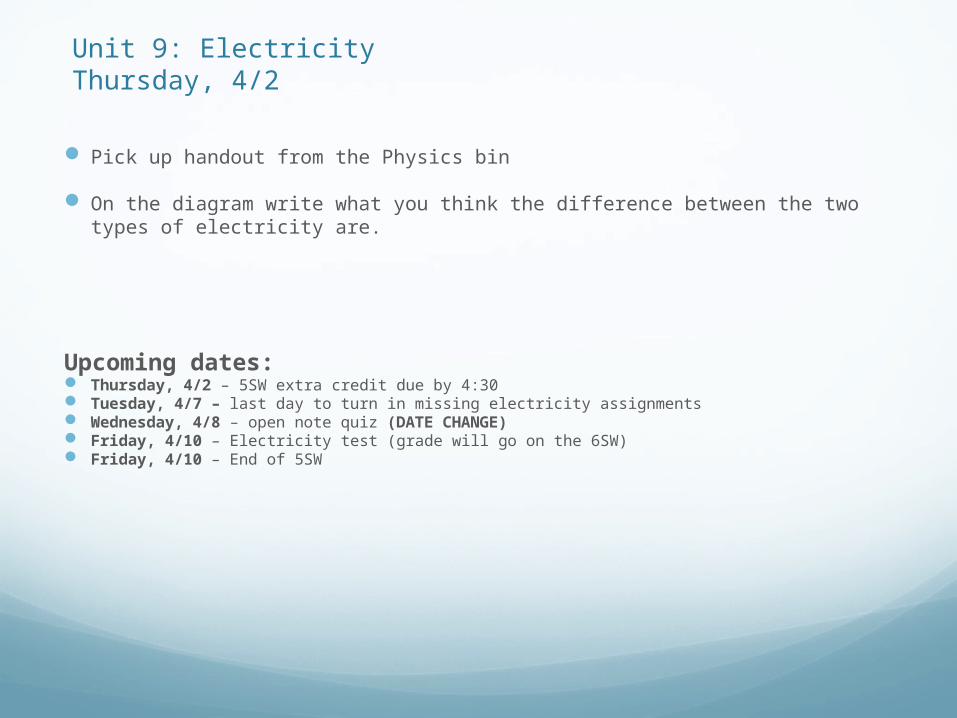
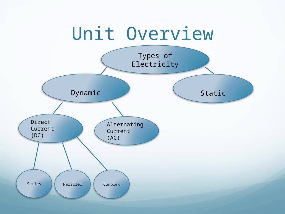
Types of Electricity
Dynamic Static
Direct Current (DC)
Alternating Current (AC)
Series ComplexParallel
Unit OverviewMotion of free charge
s
No motion of free charge
s
Electric CurrentThe continuous flow of electrons through a
conducting metal.

Alternating CurrentFlow of current that periodically changes
directionProduced in power plants
Current from a wall outlet changes direction 120 times per second
Direct CurrentThe flow of current in one consistent direction
ExamplesBatteriesSolar cells
Current from a battery travels from the positive terminal to the negative terminal.

Common Language
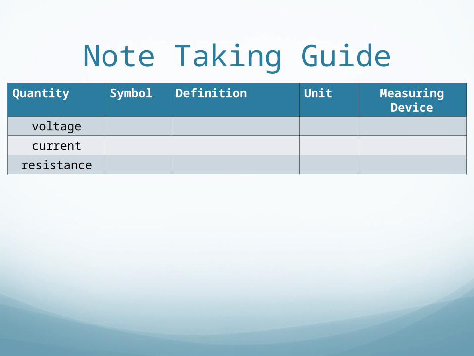
Note Taking GuideQuantity Symbol Definition Unit Measuring
Device
voltage
current
resistance
Voltage
Voltage (V) (also know as Potential Difference) can be thought of as the force pushing electric charges along a conductor. Voltage between two points creates an electric field.Measured in Volts (V)
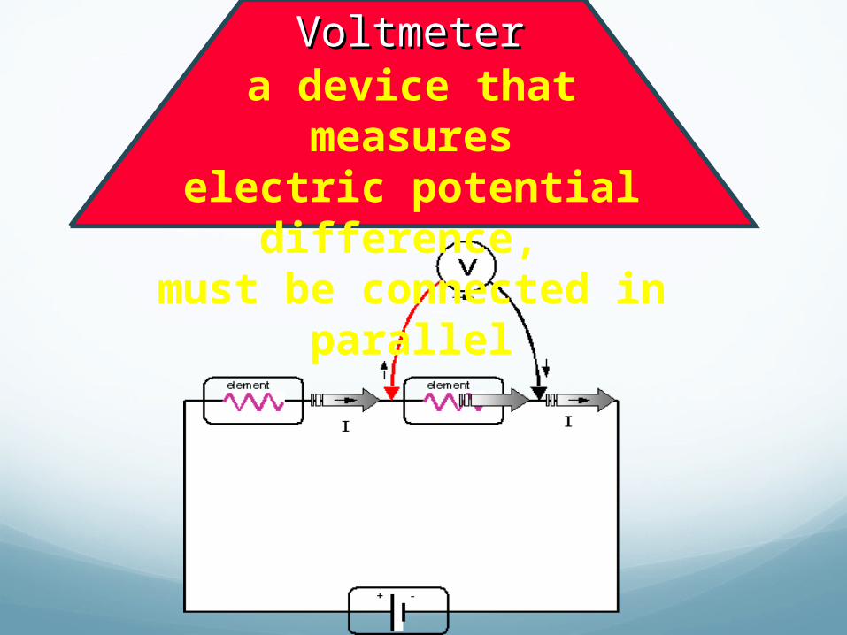
VoltmeterVoltmetera device that measures
electric potential difference, must be connected in parallel
CurrentElectric current (I) is the movement of
electric charge in a conductor.Measured in Amps (A)

AmmeterAmmetera device that measures current
attached in series
ResistanceResistance (R) is a measure of how difficult it is
to push the charges along.
The energy is transformed at the resistor (potential energy is converted).
Examples: light bulb, charging your phone, making coffee, etc.Measured in Ohms (
Note Taking GuideQuantity Symbol Definition Unit Measuring
Device
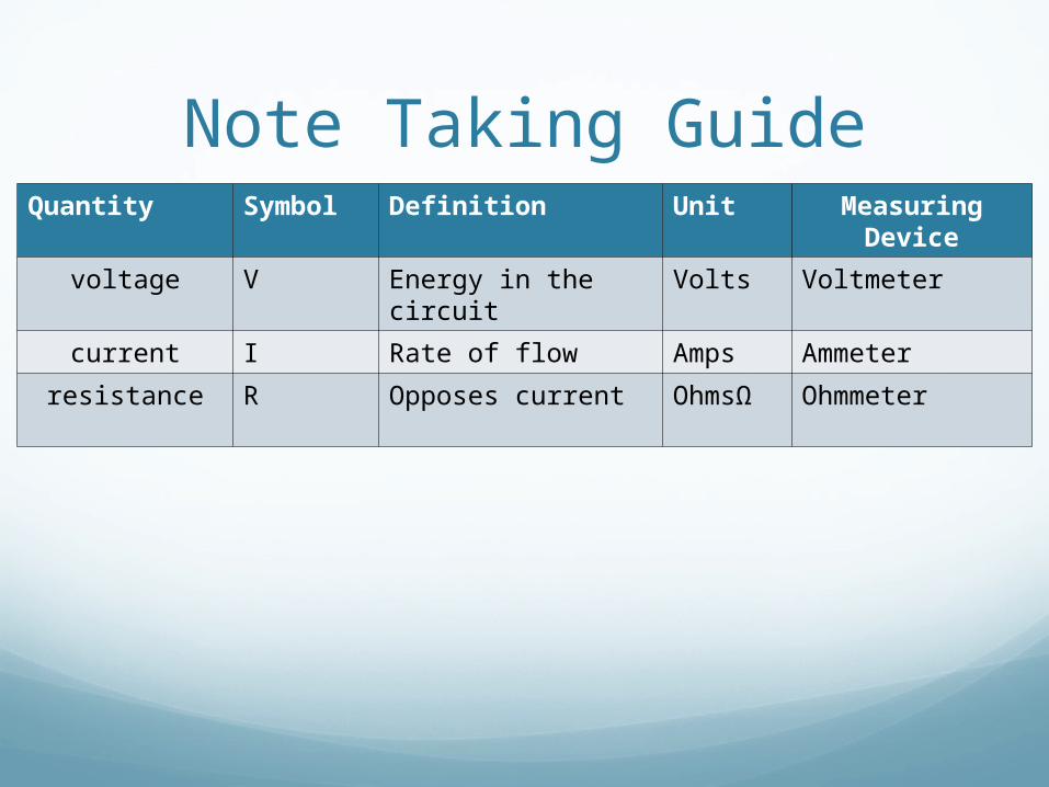
voltage V Energy in the circuit
Volts Voltmeter
current I Rate of flow Amps Ammeter
resistance R Opposes current OhmsΩ Ohmmeter

Measuring voltage and Resistance
On the back table there are circuit boards and multi-meters (you can use as a voltmeter and an ohmmeter.
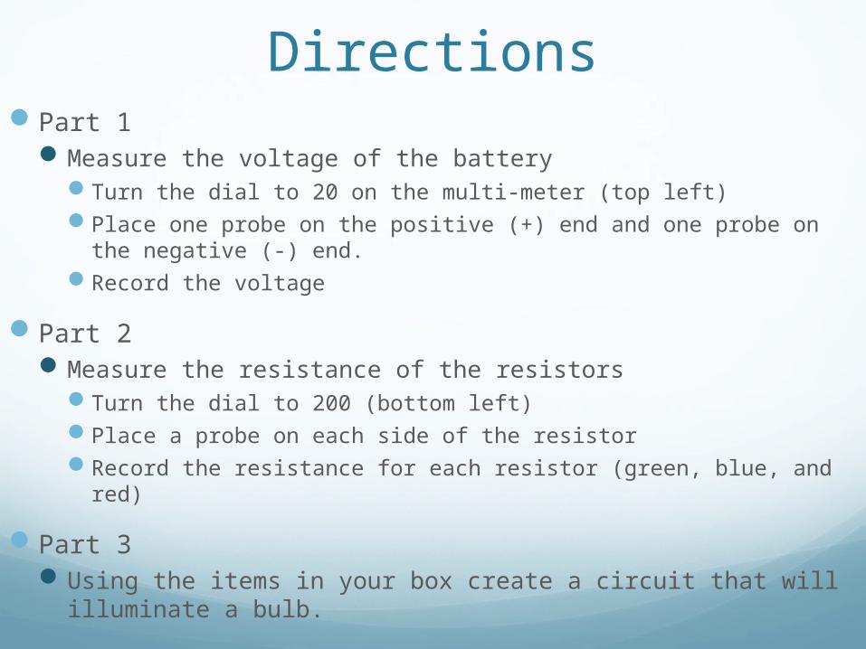
DirectionsPart 1
Measure the voltage of the batteryTurn the dial to 20 on the multi-meter (top left)Place one probe on the positive (+) end and one probe on the
negative (-) end.Record the voltage
Part 2Measure the resistance of the resistors
Turn the dial to 200 (bottom left)Place a probe on each side of the resistorRecord the resistance for each resistor (green, blue, and red)
Part 3Using the items in your box create a circuit that will
illuminate a bulb.
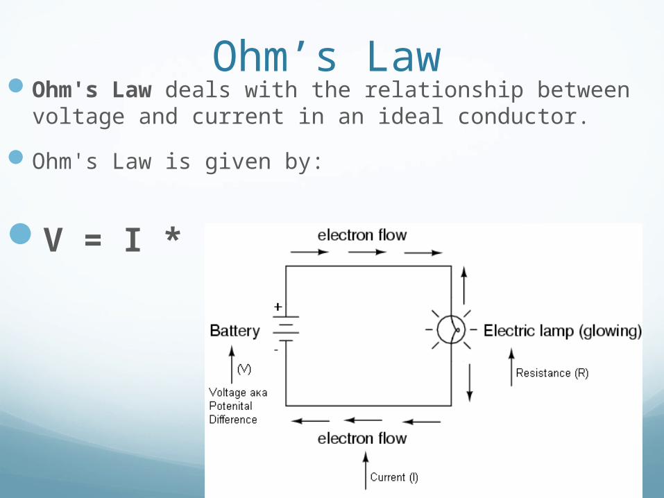
Ohm’s LawOhm's Law deals with the relationship between
voltage and current in an ideal conductor.
Ohm's Law is given by:
V = I * R
ExampleA flashlight that is powered by 3 volts and uses a bulb with a resistance of 60 ohms. What is the current flowing through the circuit?
Electrical Circuit Terminology
Circuit – a path that allows electricity to flow
Circuit diagram – a simplified representation of an electrical circuit that shows only the electrical connections of elements in a circuit.
Complete circuit – a circuit with an unbroken path that allows electrons to flow.
We will study two types of circuits:Series circuitParallel circuit

Practice
Types of Electricity
Dynamic Static
Direct Current (DC)
Alternating Current (AC)
Series ComplexParallel
Unit Overview
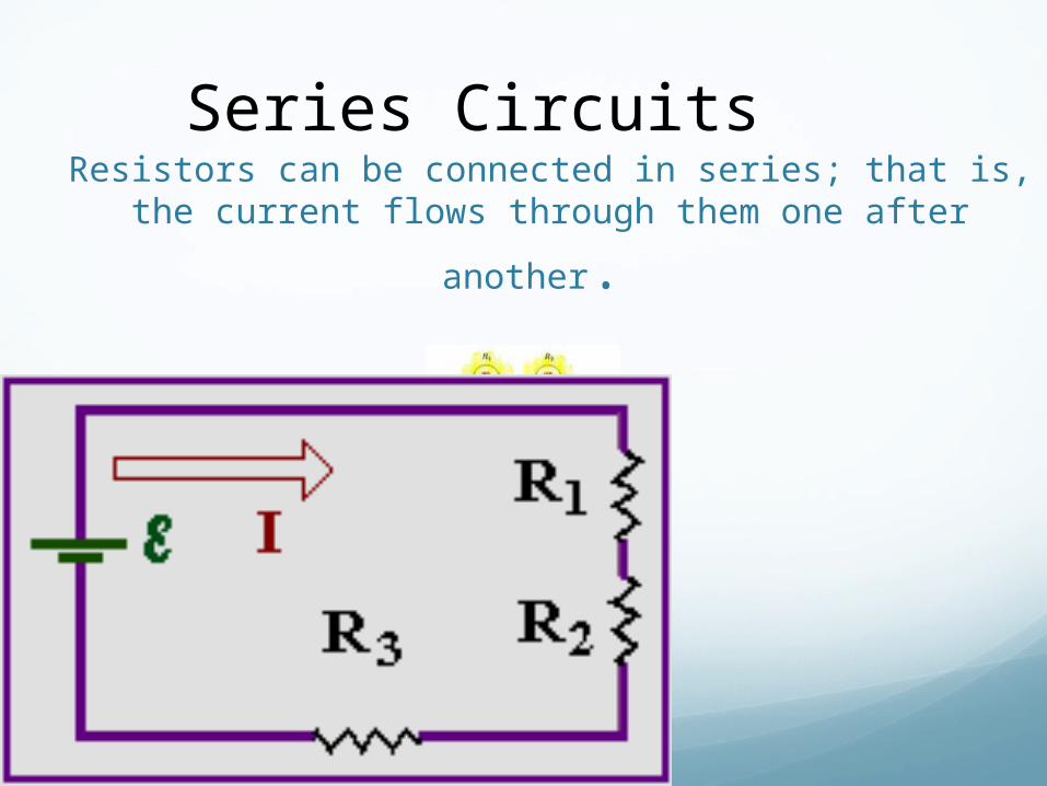
Resistors can be connected in series; that is, the
current flows through them one after another.
Series Circuits

KirchhoffKirchhoff’’s Ruless Rules
Loop Rule: Loop Rule: The sum of the potential differences The sum of the potential differences (voltage) around any closed circuit loop is zero(voltage) around any closed circuit loop is zero..
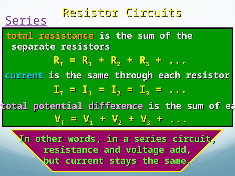
Resistor CircuitsResistor CircuitsSeries
1. 1. total resistancetotal resistance is the sum of the is the sum of the separate resistorsseparate resistors
RRTT = R = R11 + R + R22 + R + R33 + ... + ...
2. 2. currentcurrent is the same through each resistor is the same through each resistor
IITT = I = I11 = I = I22 = I = I33 = ... = ...
3. 3. total potential differencetotal potential difference is the sum of each is the sum of each
VVTT = V = V11 + V + V22 + V + V33 + ... + ...
In other words, in a series circuit,In other words, in a series circuit,resistance and voltage add,resistance and voltage add,but current stays the same.but current stays the same.
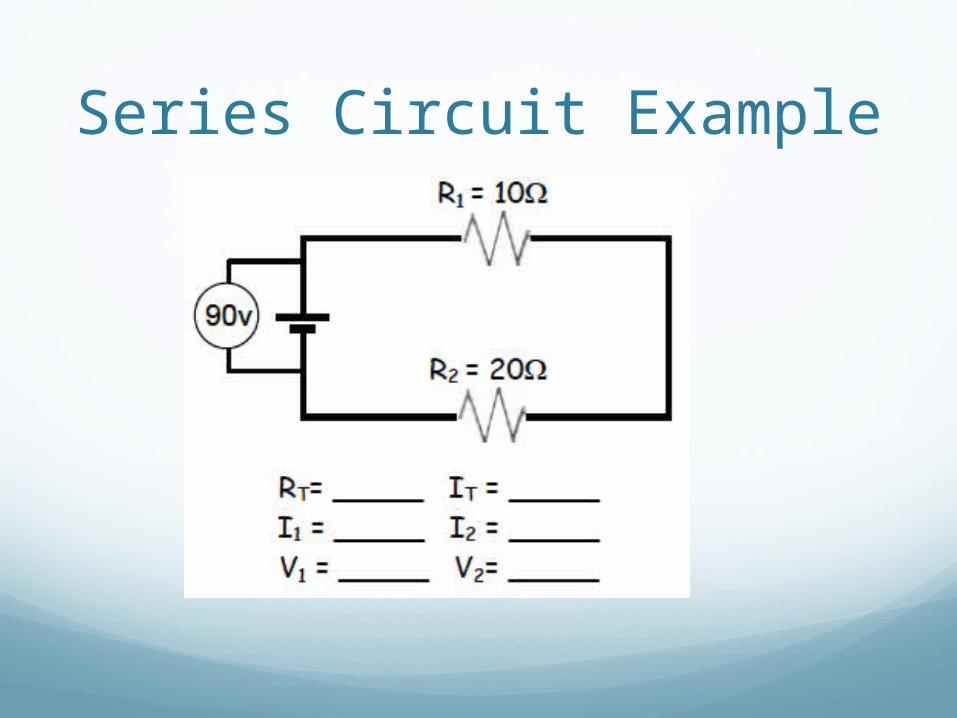
Series Circuit Example