Embed Size (px)
Citation preview

Electricity and MagnetismCapacitance
Capacitors in Series and Parallel
Lana Sheridan
De Anza College
Jan 30, 2018

Last time
• Van de Graaff generator
• capacitors
• capacitance
• capacitors of different shapes

Warm Up Question
True or false: A component (fixed) capacitor has a capacitance,even when storing no charge.
(A) true
(B) false

Warm Up Question
True or false: A component (fixed) capacitor has a capacitance,even when storing no charge.
(A) true←(B) false

Overview
• Parallel plate capacitors
• capacitors of different shapes
• Circuits and circuit diagrams
• Capacitors in series and parallel

CapacitanceCapacitors with different construction will have different values ofC .
For example,for a parallel plate capacitor: C = ε0A
d .
for a cylinderical capacitor of length L, inner radius a and outerradius b:
C = 2πε0L
ln(b/a)
for a spherical capacitor of inner radius a and outer radius b:
C = 4πε0ab
b − a
for an isolated charged sphere of radius R:
C = 4πε0R

Parallel Plate CapacitorBack to the parallel plate capacitor:
C =ε0A
d
Let’s justify why this expression should hold.
C =Q
|∆V |
Assuming the field inside the capacitor is uniform throughout, it isgiven by the expression for the field inside infinite planes of charge:
E =σ
ε0
Replace Q = σA and using we have:
C =σA
|∆V |

Parallel Plate Capacitor
Also:
∆V = −
∫E · ds = −Ed
so:
C =Q
|∆V |=σA
Ed
Using our value for E :
C =σA
(σ/ε0)d
Confirms that
C =ε0A
d
Cylindrical Capacitor
For a cylinderical capacitor of length `, much greater than innerradius a and outer radius b:
C = 2πε0`
ln(b/a)=
`
2ke ln(b/a)
780 Chapter 26 Capacitance and Dielectrics
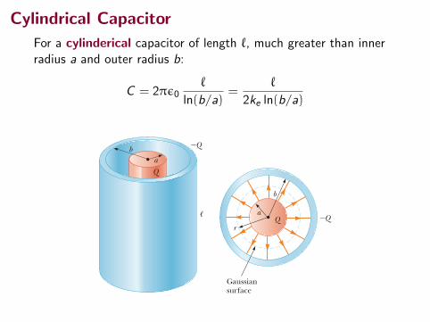
Example 26.1 The Cylindrical Capacitor
A solid cylindrical conductor of radius a and charge Q is coaxial with a cylindrical shell of negligible thick-ness, radius b . a, and charge 2Q (Fig. 26.4a). Find the capacitance of this cylindrical capacitor if its length is ,.
Conceptualize Recall that any pair of conductors qualifies as a capacitor, so the system described in this example therefore qualifies. Figure 26.4b helps visual-ize the electric field between the conductors. We expect the capacitance to depend only on geometric factors, which, in this case, are a, b, and ,.
Categorize Because of the cylindrical symmetry of the system, we can use results from previous studies of cylin-drical systems to find the capacitance.
S O L U T I O N
Substituting this result into Equation 26.1, we find that the capacitance is
C 5Q
DV5
QQd/P0A
C 5P0Ad
(26.3)
That is, the capacitance of a parallel-plate capacitor is proportional to the area of its plates and inversely proportional to the plate separation. Let’s consider how the geometry of these conductors influences the capacity of the pair of plates to store charge. As a capacitor is being charged by a battery, elec-trons flow into the negative plate and out of the positive plate. If the capacitor plates are large, the accumulated charges are able to distribute themselves over a substantial area and the amount of charge that can be stored on a plate for a given potential difference increases as the plate area is increased. Therefore, it is reason-able that the capacitance is proportional to the plate area A as in Equation 26.3. Now consider the region that separates the plates. Imagine moving the plates closer together. Consider the situation before any charges have had a chance to move in response to this change. Because no charges have moved, the electric field between the plates has the same value but extends over a shorter distance. There-fore, the magnitude of the potential difference between the plates DV 5 Ed (Eq. 25.6) is smaller. The difference between this new capacitor voltage and the terminal voltage of the battery appears as a potential difference across the wires connecting the battery to the capacitor, resulting in an electric field in the wires that drives more charge onto the plates and increases the potential difference between the plates. When the potential difference between the plates again matches that of the battery, the flow of charge stops. Therefore, moving the plates closer together causes the charge on the capacitor to increase. If d is increased, the charge decreases. As a result, the inverse relationship between C and d in Equation 26.3 is reasonable.
Q uick Quiz 26.2 Many computer keyboard buttons are constructed of capacitors as shown in Figure 26.3. When a key is pushed down, the soft insulator between the movable plate and the fixed plate is compressed. When the key is pressed, what happens to the capacitance? (a) It increases. (b) It decreases. (c) It changes in a way you cannot determine because the electric circuit connected to the key-board button may cause a change in DV.
Capacitance of parallel plates X
KeyB
Movable plate
InsulatorFixed plate
Figure 26.3 (Quick Quiz 26.2) One type of computer keyboard button.
ba
!
Gaussiansurface
!Q
!Q
aQ
Q
b
r
a b
Figure 26.4 (Example 26.1) (a) A cylindrical capacitor consists of a solid cylindrical conductor of radius a and length , sur-rounded by a coaxial cylindrical shell of radius b. (b) End view. The electric field lines are radial. The dashed line represents the end of a cylindrical gaussian surface of radius r and length ,.

Cylindrical CapacitorIdea: First find ∆V across the plates, assuming charge Q, thenevaluate Q/|∆V |.
Let λ = Q/` be the charge per unit length.
|∆V | = Va − Vb = −
∫ab
E · ds
= −
∫ab
(2keλ
r
)dr
= 2keλ ln
(b
a
)Capacitance,
C =Q
∆V=
Q
2keλ ln(ba
)C =
2πε0`
ln(ba
)

Cylindrical CapacitorIdea: First find ∆V across the plates, assuming charge Q, thenevaluate Q/|∆V |.
Let λ = Q/` be the charge per unit length.
|∆V | = Va − Vb = −
∫ab
E · ds
= −
∫ab
(2keλ
r
)dr
= 2keλ ln
(b
a
)
Capacitance,
C =Q
∆V=
Q
2keλ ln(ba
)C =
2πε0`
ln(ba
)

Cylindrical CapacitorIdea: First find ∆V across the plates, assuming charge Q, thenevaluate Q/|∆V |.
Let λ = Q/` be the charge per unit length.
|∆V | = Va − Vb = −
∫ab
E · ds
= −
∫ab
(2keλ
r
)dr
= 2keλ ln
(b
a
)Capacitance,
C =Q
∆V=
Q
2keλ ln(ba
)C =
2πε0`
ln(ba
)

Spherical CapacitorFor a spherical capacitor of inner radius a and outer radius b:
C = 4πε0ab
b − a=
ab
ke (b − a)
782 Chapter 26 Capacitance and Dielectrics
26.3 Combinations of CapacitorsTwo or more capacitors often are combined in electric circuits. We can calculate the equivalent capacitance of certain combinations using methods described in this section. Throughout this section, we assume the capacitors to be combined are initially uncharged. In studying electric circuits, we use a simplified pictorial representation called a circuit diagram. Such a diagram uses circuit symbols to represent various circuit elements. The circuit symbols are connected by straight lines that represent the wires between the circuit elements. The circuit symbols for capacitors, batteries, and switches as well as the color codes used for them in this text are given in Fig-ure 26.6. The symbol for the capacitor reflects the geometry of the most common model for a capacitor, a pair of parallel plates. The positive terminal of the battery is at the higher potential and is represented in the circuit symbol by the longer line.
Parallel CombinationTwo capacitors connected as shown in Figure 26.7a are known as a parallel combi-nation of capacitors. Figure 26.7b shows a circuit diagram for this combination of capacitors. The left plates of the capacitors are connected to the positive terminal of the battery by a conducting wire and are therefore both at the same electric potential
Substitute the absolute value of DV into Equation 26.1: C 5Q
DV5
Q0 Vb 2 Va 0 5ab
ke 1b 2 a 2 (26.6)
Apply the result of Example 24.3 for the electric field outside a spherically symmetric charge distribution and note that E
S is parallel to d sS along a radial line:
Vb 2 Va 5 2 3b
a Er dr 5 2keQ 3
b
a drr 2 5 keQ c1r d b
a
(1) Vb 2 Va 5 keQ a1b
21ab 5 keQ
a 2 bab
Write an expression for the potential difference between the two conductors from Equation 25.3:
Vb 2 Va 5 2 3b
aES
? d sS
Finalize The capacitance depends on a and b as expected. The potential difference between the spheres in Equation (1) is negative because Q is positive and b . a. Therefore, in Equation 26.6, when we take the absolute value, we change a 2 b to b 2 a. The result is a positive number.
If the radius b of the outer sphere approaches infinity, what does the capacitance become?
Answer In Equation 26.6, we let b S `:
C 5 limb S `
abke 1b 2 a 2 5
abke 1b 2 5
ake
5 4pP0a
Notice that this expression is the same as Equation 26.2, the capacitance of an isolated spherical conductor.
WHAT IF ?
Capacitorsymbol
Batterysymbol
symbolSwitch Open
Closed
!
"
Figure 26.6 Circuit symbols for capacitors, batteries, and switches. Notice that capacitors are in blue, batteries are in green, and switches are in red. The closed switch can carry current, whereas the open one cannot.
▸ 26.2 c o n t i n u e d
Categorize Because of the spherical symmetry of the sys-tem, we can use results from previous studies of spherical systems to find the capacitance.
Analyze As shown in Chapter 24, the direction of the electric field outside a spherically symmetric charge distribution is radial and its magnitude is given by the expression E 5 keQ /r 2. In this case, this result applies to the field between the spheres (a , r , b).
a
b
!Q
"Q
Figure 26.5 (Example 26.2) A spherical capacitor consists of an inner sphere of radius a sur-rounded by a concentric spherical shell of radius b. The electric field between the spheres is directed radially outward when the inner sphere is positively charged.

Spherical Capacitor
|∆V | = Va − Vb = −
∫ab
E · ds
= −
∫ab
(keQ
r2
)dr
= keQ
(1
a−
1
b
)= keQ
(b − a
ab
)
Capacitance,
C =Q
∆V
C =ab
ke (b − a)

Spherical Capacitor
|∆V | = Va − Vb = −
∫ab
E · ds
= −
∫ab
(keQ
r2
)dr
= keQ
(1
a−
1
b
)= keQ
(b − a
ab
)
Capacitance,
C =Q
∆V
C =ab
ke (b − a)

Capacitance of Isolated Conductors
Isolated conductors on their own (not part of a pair) can also besaid to have a capacitance.
The “other plate” is taken to be infinitely far away.
The capacitance is found by dividing the charge on the conductorby it’s electric potential, taking V (∞) = 0

Capacitance of and Isolated Spherical Conductor
For an isolated charged sphere of radius R:
C = 4πε0R =R
ke
Two ways to argue this,
(1) set a = R and take b →∞ in C = abke(b−a) , or
(2) recall that the potential of a sphere of charge Q is V = keQR

Circuits
Circuits consist of electrical components connected by wires.
Some types of components: batteries, resistors, capacitors,lightbulbs, LEDs, diodes, inductors, transistors, chips, etc.
The wires in circuits can be thought of as channels for an electricfield that distributes charge to (or charge flow through) thecomponents.

Circuits
The different elements can be combined together in various waysto make complete circuits: paths for charge to flow from oneterminal of a battery or power supply to the other.658 CHAPTE R 25 CAPACITANCE
HALLIDAY REVISED
that maintains a certain potential difference between its terminals (points atwhich charge can enter or leave the battery) by means of internal electrochemi-cal reactions in which electric forces can move internal charge.
In Fig. 25-4a, a battery B, a switch S, an uncharged capacitor C, and inter-connecting wires form a circuit. The same circuit is shown in the schematic dia-gram of Fig. 25-4b, in which the symbols for a battery, a switch, and a capacitorrepresent those devices. The battery maintains potential difference V between itsterminals. The terminal of higher potential is labeled ! and is often called thepositive terminal; the terminal of lower potential is labeled " and is often calledthe negative terminal.
The circuit shown in Figs. 25-4a and b is said to be incomplete becauseswitch S is open; that is, the switch does not electrically connect the wires attached to it. When the switch is closed, electrically connecting those wires, thecircuit is complete and charge can then flow through the switch and the wires.As we discussed in Chapter 21, the charge that can flow through a conductor,such as a wire, is that of electrons. When the circuit of Fig. 25-4 is completed,electrons are driven through the wires by an electric field that the battery setsup in the wires. The field drives electrons from capacitor plate h to the positiveterminal of the battery; thus, plate h, losing electrons, becomes positivelycharged. The field drives just as many electrons from the negative terminal ofthe battery to capacitor plate l; thus, plate l, gaining electrons, becomes nega-tively charged just as much as plate h, losing electrons, becomes positivelycharged.
Initially, when the plates are uncharged, the potential difference betweenthem is zero. As the plates become oppositely charged, that potential differ-ence increases until it equals the potential difference V between the terminalsof the battery. Then plate h and the positive terminal of the battery are at thesame potential, and there is no longer an electric field in the wire betweenthem. Similarly, plate l and the negative terminal reach the same potential,and there is then no electric field in the wire between them. Thus, with thefield zero, there is no further drive of electrons. The capacitor is then said tobe fully charged, with a potential difference V and charge q that are relatedby Eq. 25-1.
In this book we assume that during the charging of a capacitor and after-ward, charge cannot pass from one plate to the other across the gap separatingthem. Also, we assume that a capacitor can retain (or store) charge indefinitely,until it is put into a circuit where it can be discharged.
Fig. 25-4 (a) Battery B, switch S, and plates h and l of capacitor C, connected in a cir-cuit. (b) A schematic diagram with the circuit elements represented by their symbols.
(a)
–+B
S
hl
C
CHECKPOINT 1
Does the capacitance C of a capacitor increase, decrease, or remain the same (a) whenthe charge q on it is doubled and (b) when the potential difference V across it istripled?
l
V+–
(b)
C
B
Terminal
S
h
Terminal
halliday_c25_656-681v2.qxd 23-11-2009 14:32 Page 658
This circuit is said to be incomplete while the switch is open.

Circuit component symbols
battery ∆V
782 Chapter 26 Capacitance and Dielectrics
26.3 Combinations of CapacitorsTwo or more capacitors often are combined in electric circuits. We can calculate the equivalent capacitance of certain combinations using methods described in this section. Throughout this section, we assume the capacitors to be combined are initially uncharged. In studying electric circuits, we use a simplified pictorial representation called a circuit diagram. Such a diagram uses circuit symbols to represent various circuit elements. The circuit symbols are connected by straight lines that represent the wires between the circuit elements. The circuit symbols for capacitors, batteries, and switches as well as the color codes used for them in this text are given in Fig-ure 26.6. The symbol for the capacitor reflects the geometry of the most common model for a capacitor, a pair of parallel plates. The positive terminal of the battery is at the higher potential and is represented in the circuit symbol by the longer line.
Parallel CombinationTwo capacitors connected as shown in Figure 26.7a are known as a parallel combi-nation of capacitors. Figure 26.7b shows a circuit diagram for this combination of capacitors. The left plates of the capacitors are connected to the positive terminal of the battery by a conducting wire and are therefore both at the same electric potential
Substitute the absolute value of DV into Equation 26.1: C 5Q
DV5
Q0 Vb 2 Va 0 5ab
ke 1b 2 a 2 (26.6)
Apply the result of Example 24.3 for the electric field outside a spherically symmetric charge distribution and note that E
S is parallel to d sS along a radial line:
Vb 2 Va 5 2 3b
a Er dr 5 2keQ 3
b
a drr 2 5 keQ c1r d b
a
(1) Vb 2 Va 5 keQ a1b
21ab 5 keQ
a 2 bab
Write an expression for the potential difference between the two conductors from Equation 25.3:
Vb 2 Va 5 2 3b
aES
? d sS
Finalize The capacitance depends on a and b as expected. The potential difference between the spheres in Equation (1) is negative because Q is positive and b . a. Therefore, in Equation 26.6, when we take the absolute value, we change a 2 b to b 2 a. The result is a positive number.
If the radius b of the outer sphere approaches infinity, what does the capacitance become?
Answer In Equation 26.6, we let b S `:
C 5 limb S `
abke 1b 2 a 2 5
abke 1b 2 5
ake
5 4pP0a
Notice that this expression is the same as Equation 26.2, the capacitance of an isolated spherical conductor.
WHAT IF ?
Capacitorsymbol
Batterysymbol
symbolSwitch Open
Closed
!
"
Figure 26.6 Circuit symbols for capacitors, batteries, and switches. Notice that capacitors are in blue, batteries are in green, and switches are in red. The closed switch can carry current, whereas the open one cannot.
▸ 26.2 c o n t i n u e d
Categorize Because of the spherical symmetry of the sys-tem, we can use results from previous studies of spherical systems to find the capacitance.
Analyze As shown in Chapter 24, the direction of the electric field outside a spherically symmetric charge distribution is radial and its magnitude is given by the expression E 5 keQ /r 2. In this case, this result applies to the field between the spheres (a , r , b).
a
b
!Q
"Q
Figure 26.5 (Example 26.2) A spherical capacitor consists of an inner sphere of radius a sur-rounded by a concentric spherical shell of radius b. The electric field between the spheres is directed radially outward when the inner sphere is positively charged.
capacitor C
782 Chapter 26 Capacitance and Dielectrics
26.3 Combinations of CapacitorsTwo or more capacitors often are combined in electric circuits. We can calculate the equivalent capacitance of certain combinations using methods described in this section. Throughout this section, we assume the capacitors to be combined are initially uncharged. In studying electric circuits, we use a simplified pictorial representation called a circuit diagram. Such a diagram uses circuit symbols to represent various circuit elements. The circuit symbols are connected by straight lines that represent the wires between the circuit elements. The circuit symbols for capacitors, batteries, and switches as well as the color codes used for them in this text are given in Fig-ure 26.6. The symbol for the capacitor reflects the geometry of the most common model for a capacitor, a pair of parallel plates. The positive terminal of the battery is at the higher potential and is represented in the circuit symbol by the longer line.
Parallel CombinationTwo capacitors connected as shown in Figure 26.7a are known as a parallel combi-nation of capacitors. Figure 26.7b shows a circuit diagram for this combination of capacitors. The left plates of the capacitors are connected to the positive terminal of the battery by a conducting wire and are therefore both at the same electric potential
Substitute the absolute value of DV into Equation 26.1: C 5Q
DV5
Q0 Vb 2 Va 0 5ab
ke 1b 2 a 2 (26.6)
Apply the result of Example 24.3 for the electric field outside a spherically symmetric charge distribution and note that E
S is parallel to d sS along a radial line:
Vb 2 Va 5 2 3b
a Er dr 5 2keQ 3
b
a drr 2 5 keQ c1r d b
a
(1) Vb 2 Va 5 keQ a1b
21ab 5 keQ
a 2 bab
Write an expression for the potential difference between the two conductors from Equation 25.3:
Vb 2 Va 5 2 3b
aES
? d sS
Finalize The capacitance depends on a and b as expected. The potential difference between the spheres in Equation (1) is negative because Q is positive and b . a. Therefore, in Equation 26.6, when we take the absolute value, we change a 2 b to b 2 a. The result is a positive number.
If the radius b of the outer sphere approaches infinity, what does the capacitance become?
Answer In Equation 26.6, we let b S `:
C 5 limb S `
abke 1b 2 a 2 5
abke 1b 2 5
ake
5 4pP0a
Notice that this expression is the same as Equation 26.2, the capacitance of an isolated spherical conductor.
WHAT IF ?
Capacitorsymbol
Batterysymbol
symbolSwitch Open
Closed
!
"
Figure 26.6 Circuit symbols for capacitors, batteries, and switches. Notice that capacitors are in blue, batteries are in green, and switches are in red. The closed switch can carry current, whereas the open one cannot.
▸ 26.2 c o n t i n u e d
Categorize Because of the spherical symmetry of the sys-tem, we can use results from previous studies of spherical systems to find the capacitance.
Analyze As shown in Chapter 24, the direction of the electric field outside a spherically symmetric charge distribution is radial and its magnitude is given by the expression E 5 keQ /r 2. In this case, this result applies to the field between the spheres (a , r , b).
a
b
!Q
"Q
Figure 26.5 (Example 26.2) A spherical capacitor consists of an inner sphere of radius a sur-rounded by a concentric spherical shell of radius b. The electric field between the spheres is directed radially outward when the inner sphere is positively charged.
switch S
782 Chapter 26 Capacitance and Dielectrics
26.3 Combinations of CapacitorsTwo or more capacitors often are combined in electric circuits. We can calculate the equivalent capacitance of certain combinations using methods described in this section. Throughout this section, we assume the capacitors to be combined are initially uncharged. In studying electric circuits, we use a simplified pictorial representation called a circuit diagram. Such a diagram uses circuit symbols to represent various circuit elements. The circuit symbols are connected by straight lines that represent the wires between the circuit elements. The circuit symbols for capacitors, batteries, and switches as well as the color codes used for them in this text are given in Fig-ure 26.6. The symbol for the capacitor reflects the geometry of the most common model for a capacitor, a pair of parallel plates. The positive terminal of the battery is at the higher potential and is represented in the circuit symbol by the longer line.
Parallel CombinationTwo capacitors connected as shown in Figure 26.7a are known as a parallel combi-nation of capacitors. Figure 26.7b shows a circuit diagram for this combination of capacitors. The left plates of the capacitors are connected to the positive terminal of the battery by a conducting wire and are therefore both at the same electric potential
Substitute the absolute value of DV into Equation 26.1: C 5Q
DV5
Q0 Vb 2 Va 0 5ab
ke 1b 2 a 2 (26.6)
Apply the result of Example 24.3 for the electric field outside a spherically symmetric charge distribution and note that E
S is parallel to d sS along a radial line:
Vb 2 Va 5 2 3b
a Er dr 5 2keQ 3
b
a drr 2 5 keQ c1r d b
a
(1) Vb 2 Va 5 keQ a1b
21ab 5 keQ
a 2 bab
Write an expression for the potential difference between the two conductors from Equation 25.3:
Vb 2 Va 5 2 3b
aES
? d sS
Finalize The capacitance depends on a and b as expected. The potential difference between the spheres in Equation (1) is negative because Q is positive and b . a. Therefore, in Equation 26.6, when we take the absolute value, we change a 2 b to b 2 a. The result is a positive number.
If the radius b of the outer sphere approaches infinity, what does the capacitance become?
Answer In Equation 26.6, we let b S `:
C 5 limb S `
abke 1b 2 a 2 5
abke 1b 2 5
ake
5 4pP0a
Notice that this expression is the same as Equation 26.2, the capacitance of an isolated spherical conductor.
WHAT IF ?
Capacitorsymbol
Batterysymbol
symbolSwitch Open
Closed
!
"
Figure 26.6 Circuit symbols for capacitors, batteries, and switches. Notice that capacitors are in blue, batteries are in green, and switches are in red. The closed switch can carry current, whereas the open one cannot.
▸ 26.2 c o n t i n u e d
Categorize Because of the spherical symmetry of the sys-tem, we can use results from previous studies of spherical systems to find the capacitance.
Analyze As shown in Chapter 24, the direction of the electric field outside a spherically symmetric charge distribution is radial and its magnitude is given by the expression E 5 keQ /r 2. In this case, this result applies to the field between the spheres (a , r , b).
a
b
!Q
"Q
Figure 26.5 (Example 26.2) A spherical capacitor consists of an inner sphere of radius a sur-rounded by a concentric spherical shell of radius b. The electric field between the spheres is directed radially outward when the inner sphere is positively charged.
resistor R
820 Chapter 27 Current and Resistance
Today, thousands of superconductors are known, and as Table 27.3 illustrates, the critical temperatures of recently discovered superconductors are substantially higher than initially thought possible. Two kinds of superconductors are recog-nized. The more recently identified ones are essentially ceramics with high criti-cal temperatures, whereas superconducting materials such as those observed by Kamerlingh-Onnes are metals. If a room-temperature superconductor is ever iden-tified, its effect on technology could be tremendous. The value of Tc is sensitive to chemical composition, pressure, and molecular structure. Copper, silver, and gold, which are excellent conductors, do not exhibit superconductivity. One truly remarkable feature of superconductors is that once a current is set up in them, it persists without any applied potential difference (because R 5 0). Steady cur-rents have been observed to persist in superconducting loops for several years with no apparent decay! An important and useful application of superconductivity is in the development of superconducting magnets, in which the magnitudes of the magnetic field are approximately ten times greater than those produced by the best normal elec-tromagnets. Such superconducting magnets are being considered as a means of storing energy. Superconducting magnets are currently used in medical magnetic resonance imaging, or MRI, units, which produce high-quality images of internal organs without the need for excessive exposure of patients to x-rays or other harm-ful radiation.
27.6 Electrical PowerIn typical electric circuits, energy TET is transferred by electrical transmission from a source such as a battery to some device such as a lightbulb or a radio receiver. Let’s determine an expression that will allow us to calculate the rate of this energy transfer. First, consider the simple circuit in Figure 27.11, where energy is delivered to a resistor. (Resistors are designated by the circuit symbol .) Because the connecting wires also have resistance, some energy is delivered to the wires and some to the resistor. Unless noted otherwise, we shall assume the resistance of the wires is small compared with the resistance of the circuit element so that the energy delivered to the wires is negligible. Imagine following a positive quantity of charge Q moving clockwise around the circuit in Figure 27.11 from point a through the battery and resistor back to point a. We identify the entire circuit as our system. As the charge moves from a to b through the battery, the electric potential energy of the system increases by an amount Q DV
Table 27.3 Critical Temperatures for Various SuperconductorsMaterial Tc (K)
HgBa2Ca2Cu3O8 134Tl—Ba—Ca—Cu—O 125Bi—Sr—Ca—Cu—O 105YBa2Cu3O7 92Nb3Ge 23.2Nb3Sn 18.05Nb 9.46Pb 7.18Hg 4.15Sn 3.72Al 1.19Zn 0.88
A small permanent magnet levi-tated above a disk of the super-conductor YBa2Cu3O7, which is in liquid nitrogen at 77 K.
Cour
tesy
of I
BM R
esea
rch
Labo
rato
ry
!
b
a
c
d
R
I
V"
#
The direction of the effective flow of positive charge is clockwise.
Figure 27.11 A circuit consist-ing of a resistor of resistance R and a battery having a potential difference DV across its terminals.
inductor L
980 Chapter 32 Inductance
32.5 Oscillations in an LC CircuitWhen a capacitor is connected to an inductor as illustrated in Figure 32.10, the combination is an LC circuit. If the capacitor is initially charged and the switch is then closed, both the current in the circuit and the charge on the capacitor oscil-late between maximum positive and negative values. If the resistance of the cir-cuit is zero, no energy is transformed to internal energy. In the following analysis, the resistance in the circuit is neglected. We also assume an idealized situation in which energy is not radiated away from the circuit. This radiation mechanism is discussed in Chapter 34. Assume the capacitor has an initial charge Q max (the maximum charge) and the switch is open for t , 0 and then closed at t 5 0. Let’s investigate what happens from an energy viewpoint. When the capacitor is fully charged, the energy U in the circuit is stored in the capacitor’s electric field and is equal to Q 2
max/2C (Eq. 26.11). At this time, the current in the circuit is zero; therefore, no energy is stored in the inductor. After the switch is closed, the rate at which charges leave or enter the capacitor plates (which is also the rate at which the charge on the capacitor changes) is equal to the current in the circuit. After the switch is closed and the capacitor begins to discharge, the energy stored in its electric field decreases. The capacitor’s dis-charge represents a current in the circuit, and some energy is now stored in the magnetic field of the inductor. Therefore, energy is transferred from the electric field of the capacitor to the magnetic field of the inductor. When the capacitor is fully discharged, it stores no energy. At this time, the current reaches its maxi-mum value and all the energy in the circuit is stored in the inductor. The cur-rent continues in the same direction, decreasing in magnitude, with the capacitor eventually becoming fully charged again but with the polarity of its plates now opposite the initial polarity. This process is followed by another discharge until the circuit returns to its original state of maximum charge Q max and the plate polarity shown in Figure 32.10. The energy continues to oscillate between induc-tor and capacitor. The oscillations of the LC circuit are an electromagnetic analog to the mechani-cal oscillations of the particle in simple harmonic motion studied in Chapter 15. Much of what was discussed there is applicable to LC oscillations. For example, we investigated the effect of driving a mechanical oscillator with an external force,
S
LCQ max
!
"
Figure 32.10 A simple LC cir-cuit. The capacitor has an initial charge Q max, and the switch is open for t , 0 and then closed at t 5 0.
Find the mutual inductance, noting that the magnetic flux FBH through the handle’s coil caused by the mag-netic field of the base coil is BA:
M 5NHFBH
i5
NH BAi
5 m0 NBNH
, A
Use Equation 30.17 to express the magnetic field in the interior of the base solenoid:
B 5 m0 NB
, i
Wireless charging is used in a number of other “cordless” devices. One significant example is the inductive charging used by some manufacturers of electric cars that avoids direct metal-to-metal contact between the car and the charg-ing apparatus.
Conceptualize Be sure you can identify the two coils in the situation and understand that a changing current in one coil induces a current in the second coil.
Categorize We will determine the result using concepts discussed in this section, so we categorize this example as a substitution problem.
S O L U T I O N
▸ 32.5 c o n t i n u e d

Circuits: Batteries
782 Chapter 26 Capacitance and Dielectrics
26.3 Combinations of CapacitorsTwo or more capacitors often are combined in electric circuits. We can calculate the equivalent capacitance of certain combinations using methods described in this section. Throughout this section, we assume the capacitors to be combined are initially uncharged. In studying electric circuits, we use a simplified pictorial representation called a circuit diagram. Such a diagram uses circuit symbols to represent various circuit elements. The circuit symbols are connected by straight lines that represent the wires between the circuit elements. The circuit symbols for capacitors, batteries, and switches as well as the color codes used for them in this text are given in Fig-ure 26.6. The symbol for the capacitor reflects the geometry of the most common model for a capacitor, a pair of parallel plates. The positive terminal of the battery is at the higher potential and is represented in the circuit symbol by the longer line.
Parallel CombinationTwo capacitors connected as shown in Figure 26.7a are known as a parallel combi-nation of capacitors. Figure 26.7b shows a circuit diagram for this combination of capacitors. The left plates of the capacitors are connected to the positive terminal of the battery by a conducting wire and are therefore both at the same electric potential
Substitute the absolute value of DV into Equation 26.1: C 5Q
DV5
Q0 Vb 2 Va 0 5ab
ke 1b 2 a 2 (26.6)
Apply the result of Example 24.3 for the electric field outside a spherically symmetric charge distribution and note that E
S is parallel to d sS along a radial line:
Vb 2 Va 5 2 3b
a Er dr 5 2keQ 3
b
a drr 2 5 keQ c1r d b
a
(1) Vb 2 Va 5 keQ a1b
21ab 5 keQ
a 2 bab
Write an expression for the potential difference between the two conductors from Equation 25.3:
Vb 2 Va 5 2 3b
aES
? d sS
Finalize The capacitance depends on a and b as expected. The potential difference between the spheres in Equation (1) is negative because Q is positive and b . a. Therefore, in Equation 26.6, when we take the absolute value, we change a 2 b to b 2 a. The result is a positive number.
If the radius b of the outer sphere approaches infinity, what does the capacitance become?
Answer In Equation 26.6, we let b S `:
C 5 limb S `
abke 1b 2 a 2 5
abke 1b 2 5
ake
5 4pP0a
Notice that this expression is the same as Equation 26.2, the capacitance of an isolated spherical conductor.
WHAT IF ?
Capacitorsymbol
Batterysymbol
symbolSwitch Open
Closed
!
"
Figure 26.6 Circuit symbols for capacitors, batteries, and switches. Notice that capacitors are in blue, batteries are in green, and switches are in red. The closed switch can carry current, whereas the open one cannot.
▸ 26.2 c o n t i n u e d
Categorize Because of the spherical symmetry of the sys-tem, we can use results from previous studies of spherical systems to find the capacitance.
Analyze As shown in Chapter 24, the direction of the electric field outside a spherically symmetric charge distribution is radial and its magnitude is given by the expression E 5 keQ /r 2. In this case, this result applies to the field between the spheres (a , r , b).
a
b
!Q
"Q
Figure 26.5 (Example 26.2) A spherical capacitor consists of an inner sphere of radius a sur-rounded by a concentric spherical shell of radius b. The electric field between the spheres is directed radially outward when the inner sphere is positively charged.
Batteries cause a potential difference between two parts of thecircuit.
This can drive a charge flow. (Current is the rate of flow ofcharge.)

Series and Parallel
SeriesWhen components areconnected one after the otheralong a single path, they areconnected in series.
V
R1
R2
ParallelWhen components areconnected side-by-side ondifferent paths, they areconnected in parallel.
R1 R2
V

Capacitors in Parallel
Capacitors in parallel all have the same potential differenceacross them.
Three capacitors in parallel:
66325-4 CAPACITORS I N PARALLE L AN D I N S E R I E SPART 3
HALLIDAY REVISED
When a potential difference V is applied across several capacitors connected in parallel, that potential difference V is applied across each capacitor.The total chargeq stored on the capacitors is the sum of the charges stored on all the capacitors.
When we analyze a circuit of capacitors in parallel, we can simplify it withthis mental replacement:
Capacitors connected in parallel can be replaced with an equivalent capacitor thathas the same total charge q and the same potential difference V as the actual capacitors.
(You might remember this result with the nonsense word “par-V,” which is closeto “party,” to mean “capacitors in parallel have the same V.”) Figure 25-8b showsthe equivalent capacitor (with equivalent capacitance Ceq) that has replaced thethree capacitors (with actual capacitances C1, C2, and C3) of Fig. 25-8a.
To derive an expression for Ceq in Fig. 25-8b, we first use Eq. 25-1 to find thecharge on each actual capacitor:
q1 ! C1V, q2 ! C2V, and q3 ! C3V.
The total charge on the parallel combination of Fig. 25-8a is then
q ! q1 " q2 " q3 ! (C1 " C2 " C3)V.
The equivalent capacitance, with the same total charge q and applied potentialdifference V as the combination, is then
a result that we can easily extend to any number n of capacitors, as
(n capacitors in parallel). (25-19)
Thus, to find the equivalent capacitance of a parallel combination, we simply addthe individual capacitances.
Capacitors in SeriesFigure 25-9a shows three capacitors connected in series to battery B.This descriptionhas little to do with how the capacitors are drawn. Rather,“in series” means that thecapacitors are wired serially, one after the other, and that a potential difference V isapplied across the two ends of the series. (In Fig. 25-9a, this potential difference V ismaintained by battery B.) The potential differences that then exist across the capaci-tors in the series produce identical charges q on them.
Ceq ! !n
j!1 Cj
Ceq !qV
! C1 " C2 " C3,
Fig. 25-8 (a) Three capacitors connectedin parallel to battery B.The battery main-tains potential difference V across its termi-nals and thus across each capacitor. (b) Theequivalent capacitor, with capacitance Ceq,replaces the parallel combination.
V +q3
V – +
Terminal
C3
B
(a)
–q
+qV
+–
(b)
Ceq
B
Terminal
–q3
+q2
–q2 C2
V +q1
–q1 C1
V
Parallel capacitors andtheir equivalent havethe same V (“par-V”).
When a potential difference V is applied across several capacitors connected inseries, the capacitors have identical charge q.The sum of the potential differencesacross all the capacitors is equal to the applied potential difference V.
We can explain how the capacitors end up with identical charge by followinga chain reaction of events, in which the charging of each capacitor causes thecharging of the next capacitor. We start with capacitor 3 and work upward tocapacitor 1. When the battery is first connected to the series of capacitors, it
halliday_c25_656-681v2.qxd 23-11-2009 14:32 Page 663
Equivalent circuit:
66325-4 CAPACITORS I N PARALLE L AN D I N S E R I E SPART 3
HALLIDAY REVISED
When a potential difference V is applied across several capacitors connected in parallel, that potential difference V is applied across each capacitor.The total chargeq stored on the capacitors is the sum of the charges stored on all the capacitors.
When we analyze a circuit of capacitors in parallel, we can simplify it withthis mental replacement:
Capacitors connected in parallel can be replaced with an equivalent capacitor thathas the same total charge q and the same potential difference V as the actual capacitors.
(You might remember this result with the nonsense word “par-V,” which is closeto “party,” to mean “capacitors in parallel have the same V.”) Figure 25-8b showsthe equivalent capacitor (with equivalent capacitance Ceq) that has replaced thethree capacitors (with actual capacitances C1, C2, and C3) of Fig. 25-8a.
To derive an expression for Ceq in Fig. 25-8b, we first use Eq. 25-1 to find thecharge on each actual capacitor:
q1 ! C1V, q2 ! C2V, and q3 ! C3V.
The total charge on the parallel combination of Fig. 25-8a is then
q ! q1 " q2 " q3 ! (C1 " C2 " C3)V.
The equivalent capacitance, with the same total charge q and applied potentialdifference V as the combination, is then
a result that we can easily extend to any number n of capacitors, as
(n capacitors in parallel). (25-19)
Thus, to find the equivalent capacitance of a parallel combination, we simply addthe individual capacitances.
Capacitors in SeriesFigure 25-9a shows three capacitors connected in series to battery B.This descriptionhas little to do with how the capacitors are drawn. Rather,“in series” means that thecapacitors are wired serially, one after the other, and that a potential difference V isapplied across the two ends of the series. (In Fig. 25-9a, this potential difference V ismaintained by battery B.) The potential differences that then exist across the capaci-tors in the series produce identical charges q on them.
Ceq ! !n
j!1 Cj
Ceq !qV
! C1 " C2 " C3,
Fig. 25-8 (a) Three capacitors connectedin parallel to battery B.The battery main-tains potential difference V across its termi-nals and thus across each capacitor. (b) Theequivalent capacitor, with capacitance Ceq,replaces the parallel combination.
V +q3
V – +
Terminal
C3
B
(a)
–q
+qV
+–
(b)
Ceq
B
Terminal
–q3
+q2
–q2 C2
V +q1
–q1 C1
V
Parallel capacitors andtheir equivalent havethe same V (“par-V”).
When a potential difference V is applied across several capacitors connected inseries, the capacitors have identical charge q.The sum of the potential differencesacross all the capacitors is equal to the applied potential difference V.
We can explain how the capacitors end up with identical charge by followinga chain reaction of events, in which the charging of each capacitor causes thecharging of the next capacitor. We start with capacitor 3 and work upward tocapacitor 1. When the battery is first connected to the series of capacitors, it
halliday_c25_656-681v2.qxd 23-11-2009 14:32 Page 663
We could replace all three capacitors in the circuit with oneequivalent capacitance. The current and potential difference in therest of the circuit is unchanged by this.
What would be the capacitance of this equivalent capacitor?

Capacitors in Parallel
Capacitors in parallel all have the same potential differenceacross them.
∆V1 = ∆V2 = ∆V3 = ∆V
The total charge on the three capacitors is the sum of the chargeon each.
qnet = q1 + q2 + q3
where q1 = C1∆V .
Capacitance is C = q/(∆V ):
Ceq =qnet∆V

Capacitors in Parallel
Equivalent capacitance:
Ceq =qnet∆V
=q1∆V
+q2∆V
+q3∆V
= C1 + C2 + C3
So in general, for any number n of capacitors in parallel, theeffective capacitance of them all together is:
Ceq = C1 + C2 + ... + Cn =
n∑i=1
Ci

Capacitors in Parallel
Equivalent capacitance:
Ceq =qnet∆V
=q1∆V
+q2∆V
+q3∆V
= C1 + C2 + C3
So in general, for any number n of capacitors in parallel, theeffective capacitance of them all together is:
Ceq = C1 + C2 + ... + Cn =
n∑i=1
Ci

Capacitors in Series
Capacitors in series all store the same charge.
Three capacitors in series:664 CHAPTE R 25 CAPACITANCE
HALLIDAY REVISED
produces charge !q on the bottom plate of capacitor 3. That charge then repelsnegative charge from the top plate of capacitor 3 (leaving it with charge "q).Therepelled negative charge moves to the bottom plate of capacitor 2 (giving itcharge !q). That charge on the bottom plate of capacitor 2 then repels negativecharge from the top plate of capacitor 2 (leaving it with charge "q) to the bottomplate of capacitor 1 (giving it charge !q). Finally, the charge on the bottom plateof capacitor 1 helps move negative charge from the top plate of capacitor 1 to thebattery, leaving that top plate with charge "q.
Here are two important points about capacitors in series:
1. When charge is shifted from one capacitor to another in a series of capacitors,it can move along only one route, such as from capacitor 3 to capacitor 2 in Fig. 25-9a. If there are additional routes, the capacitors are not in series.
2. The battery directly produces charges on only the two plates to which it isconnected (the bottom plate of capacitor 3 and the top plate of capacitor 1 inFig. 25-9a). Charges that are produced on the other plates are due merely tothe shifting of charge already there. For example, in Fig. 25-9a, the part of thecircuit enclosed by dashed lines is electrically isolated from the rest of thecircuit. Thus, the net charge of that part cannot be changed by the battery—its charge can only be redistributed.
When we analyze a circuit of capacitors in series, we can simplify it with thismental replacement:
(You might remember this with the nonsense word “seri-q” to mean “capacitorsin series have the same q.”) Figure 25-9b shows the equivalent capacitor (withequivalent capacitance Ceq) that has replaced the three actual capacitors(with actual capacitances C1, C2, and C3) of Fig. 25-9a.
To derive an expression for Ceq in Fig. 25-9b, we first use Eq. 25-1 to find thepotential difference of each actual capacitor:
The total potential difference V due to the battery is the sum of these threepotential differences.Thus,
The equivalent capacitance is then
or
We can easily extend this to any number n of capacitors as
(n capacitors in series). (25-20)
Using Eq. 25-20 you can show that the equivalent capacitance of a series ofcapacitances is always less than the least capacitance in the series.
1Ceq
# !n
j#1
1Cj
1Ceq
#1
C1"
1C2
"1
C3.
Ceq #qV
#1
1/C1 " 1/C2 " 1/C3,
V # V1 " V2 " V3 # q " 1C1
"1
C2"
1C3
#.
V1 #qC1
, V2 #qC2
, and V3 #qC3
.
Fig. 25-9 (a) Three capacitors con-nected in series to battery B.The batterymaintains potential difference V betweenthe top and bottom plates of the seriescombination. (b) The equivalent capacitor,with capacitance Ceq, replaces the seriescombination.
Capacitors that are connected in series can be replaced with an equivalent capacitor thathas the same charge q and the same total potential difference V as the actual series capacitors.
CHECKPOINT 3
A battery of potential V stores charge qon a combination of two identical ca-pacitors. What are the potential differ-ence across and the charge on either ca-pacitor if the capacitors are (a) inparallel and (b) in series?
V
(b)
Ceq
V + –
(a)
B
+q
C1
C2
C3
V1
V2
V3
– +
B
Terminal
Terminal
–q
+q
–q
–q
+q
–q
+q
Series capacitors andtheir equivalent havethe same q (“seri-q”).
halliday_c25_656-681v2.qxd 23-11-2009 14:32 Page 664
Equivalent circuit:
664 CHAPTE R 25 CAPACITANCE
HALLIDAY REVISED
produces charge !q on the bottom plate of capacitor 3. That charge then repelsnegative charge from the top plate of capacitor 3 (leaving it with charge "q).Therepelled negative charge moves to the bottom plate of capacitor 2 (giving itcharge !q). That charge on the bottom plate of capacitor 2 then repels negativecharge from the top plate of capacitor 2 (leaving it with charge "q) to the bottomplate of capacitor 1 (giving it charge !q). Finally, the charge on the bottom plateof capacitor 1 helps move negative charge from the top plate of capacitor 1 to thebattery, leaving that top plate with charge "q.
Here are two important points about capacitors in series:
1. When charge is shifted from one capacitor to another in a series of capacitors,it can move along only one route, such as from capacitor 3 to capacitor 2 in Fig. 25-9a. If there are additional routes, the capacitors are not in series.
2. The battery directly produces charges on only the two plates to which it isconnected (the bottom plate of capacitor 3 and the top plate of capacitor 1 inFig. 25-9a). Charges that are produced on the other plates are due merely tothe shifting of charge already there. For example, in Fig. 25-9a, the part of thecircuit enclosed by dashed lines is electrically isolated from the rest of thecircuit. Thus, the net charge of that part cannot be changed by the battery—its charge can only be redistributed.
When we analyze a circuit of capacitors in series, we can simplify it with thismental replacement:
(You might remember this with the nonsense word “seri-q” to mean “capacitorsin series have the same q.”) Figure 25-9b shows the equivalent capacitor (withequivalent capacitance Ceq) that has replaced the three actual capacitors(with actual capacitances C1, C2, and C3) of Fig. 25-9a.
To derive an expression for Ceq in Fig. 25-9b, we first use Eq. 25-1 to find thepotential difference of each actual capacitor:
The total potential difference V due to the battery is the sum of these threepotential differences.Thus,
The equivalent capacitance is then
or
We can easily extend this to any number n of capacitors as
(n capacitors in series). (25-20)
Using Eq. 25-20 you can show that the equivalent capacitance of a series ofcapacitances is always less than the least capacitance in the series.
1Ceq
# !n
j#1
1Cj
1Ceq
#1
C1"
1C2
"1
C3.
Ceq #qV
#1
1/C1 " 1/C2 " 1/C3,
V # V1 " V2 " V3 # q " 1C1
"1
C2"
1C3
#.
V1 #qC1
, V2 #qC2
, and V3 #qC3
.
Fig. 25-9 (a) Three capacitors con-nected in series to battery B.The batterymaintains potential difference V betweenthe top and bottom plates of the seriescombination. (b) The equivalent capacitor,with capacitance Ceq, replaces the seriescombination.
Capacitors that are connected in series can be replaced with an equivalent capacitor thathas the same charge q and the same total potential difference V as the actual series capacitors.
CHECKPOINT 3
A battery of potential V stores charge qon a combination of two identical ca-pacitors. What are the potential differ-ence across and the charge on either ca-pacitor if the capacitors are (a) inparallel and (b) in series?
V
(b)
Ceq
V + –
(a)
B
+q
C1
C2
C3
V1
V2
V3
– +
B
Terminal
Terminal
–q
+q
–q
–q
+q
–q
+q
Series capacitors andtheir equivalent havethe same q (“seri-q”).
halliday_c25_656-681v2.qxd 23-11-2009 14:32 Page 664

Summary
• parallel plate capacitors
• capacitors of different shapes
• circuits, circuit diagrams
• capacitors in parallel
HomeworkSerway & Jewett:
• PREVIOUS: Ch 26, onward from page 799. Problems: 1, 5, 7,11, 51
• NEW: Ch 26. Problems: 13