Embed Size (px)
Citation preview
ELECTRICALLY DRIVEN AND CONTROLLED LANDING GEAR FOR
UAV UP TO 100KG OF TAKE OFF MASS
Zbigniew SKORUPKA, Wojciech KOWALSKI and Rafał KAJKA
Institute of Aviation
02-256 Warsaw, Poland
E-mail: [email protected]
KEYWORDS
UAV, Unmanned Aerial Vehicle, landing gear, IA.
ABSTRACT
UAV - Unmanned Aerial Vehicle is very rapidly
growing area of flying objects. Various tasks and
possible areas of UAVs use are generating increasing
demand for various types and designs. Thanks to
simpler certification requirements UAV market could be
used as a test field for various new technologies like
wide use of modern electric systems. One of the area
where electric systems could be implemented is a
landing gears with its steering, braking or retraction /
extension systems.
1. WHAT IS UAV?
An Unmanned Aerial Vehicle is an aircraft without any
human crew. It is controlled remotely from stationary or
mobile command center. UAV control is performed by
radio (directly from ground or via satellites for wider
ranges of operation) or autonomously (by on board
computers). Autonomous control of the UAV is based
on pre-programmed flight plans using complex
automation systems.
Figure 1. UAV monitoring and control at CBP
(photo: Wikipedia)
UAV main use is military. It can perform attack or
reconnaissance missions.
For reconnaissance missions UAV’s are often equipped
with variety of cameras (from normal video cameras to
high resolution infrared ones) and sensors ex. for
sensing nuclear or chemical weapons.
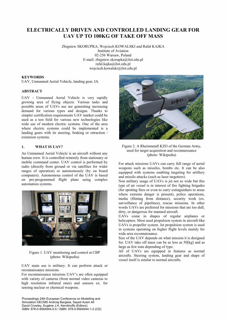
Figure 2. A Rheinmetall KZO of the German Army,
used for target acquisition and reconnaissance
(photo: Wikipedia)
For attack missions UAVs can carry full range of aerial
weapons such as missiles, bombs etc. It can be also
equipped with systems enabling targeting for artillery
and missile attacks (such as laser targetters).
Non military usage of UAVs is jet not so wide but this
type of air vessel is in interest of fire fighting brigades
(for spotting fires or even to carry extinguishers to areas
where extreme danger is present), police operations,
media (filming from distance), security work (ex.
surveillance of pipelines), rescue missions. In other
words UAVs are preferred for missions that are too dull,
dirty, or dangerous for manned aircraft.
UAVs come in shapes of regular airplanes or
helicopters. Most used propulsion system in aircraft-like
UAVs is propeller system. Jet propulsion system is used
in systems operating on higher flight levels mainly for
wide area reconnaissance.
Size of the UAV depends on what mission it is designed
for. UAV take off mass can be as less as 50[kg] and as
large as few tons depending of type.
All of UAVs are equipped in features as normal
aircrafts. Steering system, landing gear and shape of
vessel itself is similar to normal aircrafts.
Proceedings 24th European Conference on Modelling andSimulation ©ECMS Andrzej Bargiela, Sayed Azam AliDavid Crowley, Eugène J.H. Kerckhoffs (Editors)ISBN: 978-0-9564944-0-5 / ISBN: 978-0-9564944-1-2 (CD)
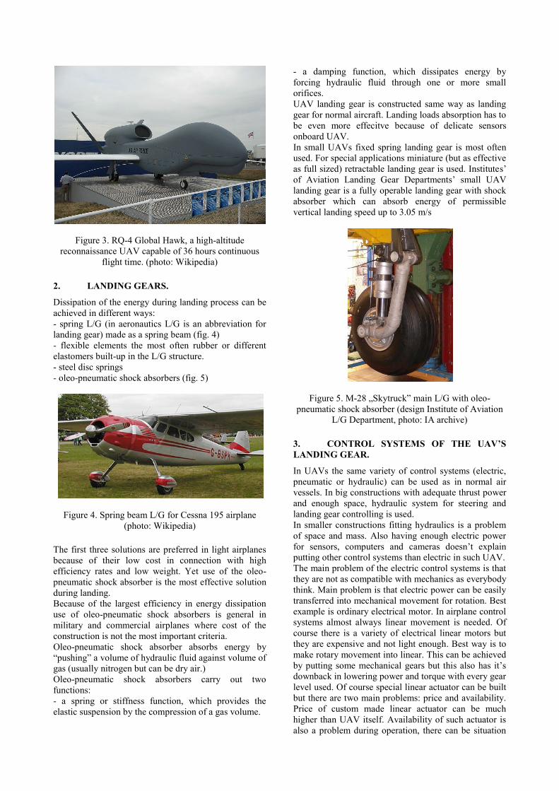
Figure 3. RQ-4 Global Hawk, a high-altitude
reconnaissance UAV capable of 36 hours continuous
flight time. (photo: Wikipedia)
2. LANDING GEARS.
Dissipation of the energy during landing process can be
achieved in different ways:
- spring L/G (in aeronautics L/G is an abbreviation for
landing gear) made as a spring beam (fig. 4)
- flexible elements the most often rubber or different
elastomers built-up in the L/G structure.
- steel disc springs
- oleo-pneumatic shock absorbers (fig. 5)
Figure 4. Spring beam L/G for Cessna 195 airplane
(photo: Wikipedia)
The first three solutions are preferred in light airplanes
because of their low cost in connection with high
efficiency rates and low weight. Yet use of the oleo-
pneumatic shock absorber is the most effective solution
during landing.
Because of the largest efficiency in energy dissipation
use of oleo-pneumatic shock absorbers is general in
military and commercial airplanes where cost of the
construction is not the most important criteria.
Oleo-pneumatic shock absorber absorbs energy by
“pushing” a volume of hydraulic fluid against volume of
gas (usually nitrogen but can be dry air.)
Oleo-pneumatic shock absorbers carry out two
functions:
- a spring or stiffness function, which provides the
elastic suspension by the compression of a gas volume.
- a damping function, which dissipates energy by
forcing hydraulic fluid through one or more small
orifices.
UAV landing gear is constructed same way as landing
gear for normal aircraft. Landing loads absorption has to
be even more effecitve because of delicate sensors
onboard UAV.
In small UAVs fixed spring landing gear is most often
used. For special applications miniature (but as effective
as full sized) retractable landing gear is used. Institutes’
of Aviation Landing Gear Departments’ small UAV
landing gear is a fully operable landing gear with shock
absorber which can absorb energy of permissible
vertical landing speed up to 3.05 m/s
Figure 5. M-28 „Skytruck” main L/G with oleo-
pneumatic shock absorber (design Institute of Aviation
L/G Department, photo: IA archive)
3. CONTROL SYSTEMS OF THE UAV’S
LANDING GEAR.
In UAVs the same variety of control systems (electric,
pneumatic or hydraulic) can be used as in normal air
vessels. In big constructions with adequate thrust power
and enough space, hydraulic system for steering and
landing gear controlling is used.
In smaller constructions fitting hydraulics is a problem
of space and mass. Also having enough electric power
for sensors, computers and cameras doesn’t explain
putting other control systems than electric in such UAV.
The main problem of the electric control systems is that
they are not as compatible with mechanics as everybody
think. Main problem is that electric power can be easily
transferred into mechanical movement for rotation. Best
example is ordinary electrical motor. In airplane control
systems almost always linear movement is needed. Of
course there is a variety of electrical linear motors but
they are expensive and not light enough. Best way is to
make rotary movement into linear. This can be achieved
by putting some mechanical gears but this also has it’s
downback in lowering power and torque with every gear
level used. Of course special linear actuator can be built
but there are two main problems: price and availability.
Price of custom made linear actuator can be much
higher than UAV itself. Availability of such actuator is
also a problem during operation, there can be situation
in which UAV is grounded for weeks because of time
for actuator manufacturing time.
Figure 6. Nose Landing Gear on test stand in Laboratory
(photo: IA archive)
These aspects were taken into account during landing
gear planning phase in Landing Gear Department. First
of all low (100kg) take off mass and plenty of electric
power onboard made not reasonable of taking into the
account hydraulic control systems.
Second cost of landing gear system had to be acceptable
and active parts of the landing gear had to be easily
available.
Also there was no restriction of using aviation grade
parts because these regulations only apply when air
vessel is carrying humans. For non-human aircrafts
there is only need of using parts which are reliable
enough.
Figure 7. Main Landing Gear on test stand in
Laboratory (photo: IA archive)
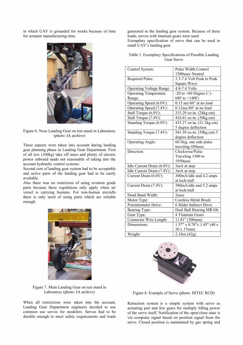
When all restrictions were taken into the account,
Landing Gear Department engineers decided to use
common use servos for modelers. Servos had to be
durable enough to meet safety requirements and loads
generated in the landing gear system. Because of these
loads, servos with titanium gears were used.
Exemplary specification of servo that can be used in
small UAV’s landing gear.
Table 1. Exemplary Specifications of Possible Landing
Gear Servo
Control System: Pulse Width Control
1500usec Neutral
Required Pulse: 3.3-7.4 Volt Peak to Peak
Square Wave
Operating Voltage Range: 4.8-7.4 Volts
Operating Temperature
Range:
-20 to +60 Degree C (-
68F to +140F)
Operating Speed (6.0V): 0.15 sec/60° at no load
Operating Speed (7.4V): 0.12sec/60° at no load
Stall Torque (6.0V): 333.29 oz-in. (24kg.cm)
Stall Torque (7.4V): 416.61 oz-in. (30kg.cm)
Standing Torque (6.0V): 433.27 oz-in. (31.2kg.cm)
5 degree deflection
Standing Torque (7.4V): 541.59 oz-in. (39kg.cm) 5
degree deflection
Operating Angle: 60 Deg. one side pulse
traveling 450usec
Direction: Clockwise/Pulse
Traveling 1500 to
1950usec
Idle Current Drain (6.0V): 3mA at stop
Idle Current Drain (7.4V): 3mA at stop
Current Drain (6.0V): 300mA/idle and 4.2 amps
at lock/stall
Current Drain (7.4V): 380mA/idle and 5.2 amps
at lock/stall
Dead Band Width: 2usec
Motor Type: Coreless Metal Brush
Potentiometer Drive: 6 Slider Indirect Drive
Bearing Type: Dual Ball Bearing MR106
Gear Type: 4 Titanium Gears
Connector Wire Length: 11.81" (300mm)
Dimensions: 1.57" x 0.78"x 1.45" (40 x
20 x 37mm)
Weight: 2.18oz (62g)
Figure 8. Example of Servo (photo: HITEC RCD)
Retraction system is a simple system with servo as
actuating part and few gears for multiply lifting power
of the servo itself. Notification of the open/close state is
via computer signal based on position signal from the
servo. Closed position is maintained by gas spring and
by computer signal to servo in case of unwanted
retraction. All landing gears have also gas spring used
as mechanical help during retraction/extension of the
landing gear. In retraction system servos were used
without any reconfigurations.
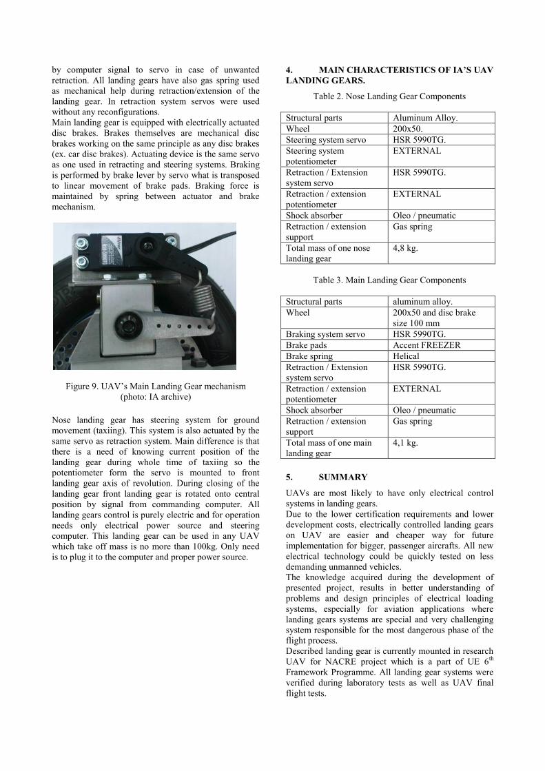
Main landing gear is equipped with electrically actuated
disc brakes. Brakes themselves are mechanical disc
brakes working on the same principle as any disc brakes
(ex. car disc brakes). Actuating device is the same servo
as one used in retracting and steering systems. Braking
is performed by brake lever by servo what is transposed
to linear movement of brake pads. Braking force is
maintained by spring between actuator and brake
mechanism.
Figure 9. UAV’s Main Landing Gear mechanism
(photo: IA archive)
Nose landing gear has steering system for ground
movement (taxiing). This system is also actuated by the
same servo as retraction system. Main difference is that
there is a need of knowing current position of the
landing gear during whole time of taxiing so the
potentiometer form the servo is mounted to front
landing gear axis of revolution. During closing of the
landing gear front landing gear is rotated onto central
position by signal from commanding computer. All
landing gears control is purely electric and for operation
needs only electrical power source and steering
computer. This landing gear can be used in any UAV
which take off mass is no more than 100kg. Only need
is to plug it to the computer and proper power source.
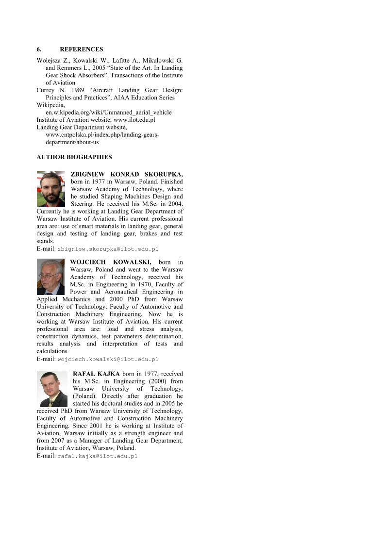
4. MAIN CHARACTERISTICS OF IA’S UAV
LANDING GEARS.
Table 2. Nose Landing Gear Components
Structural parts Aluminum Alloy.
Wheel 200x50.
Steering system servo HSR 5990TG.
Steering system
potentiometer
EXTERNAL
Retraction / Extension
system servo
HSR 5990TG.
Retraction / extension
potentiometer
EXTERNAL
Shock absorber Oleo / pneumatic
Retraction / extension
support
Gas spring
Total mass of one nose
landing gear
4,8 kg.
Table 3. Main Landing Gear Components
Structural parts aluminum alloy.
Wheel 200x50 and disc brake
size 100 mm
Braking system servo HSR 5990TG.
Brake pads Accent FREEZER
Brake spring Helical
Retraction / Extension
system servo
HSR 5990TG.
Retraction / extension
potentiometer
EXTERNAL
Shock absorber Oleo / pneumatic
Retraction / extension
support
Gas spring
Total mass of one main
landing gear
4,1 kg.
5. SUMMARY
UAVs are most likely to have only electrical control
systems in landing gears.
Due to the lower certification requirements and lower
development costs, electrically controlled landing gears
on UAV are easier and cheaper way for future
implementation for bigger, passenger aircrafts. All new
electrical technology could be quickly tested on less
demanding unmanned vehicles.
The knowledge acquired during the development of
presented project, results in better understanding of
problems and design principles of electrical loading
systems, especially for aviation applications where
landing gears systems are special and very challenging
system responsible for the most dangerous phase of the
flight process.
Described landing gear is currently mounted in research
UAV for NACRE project which is a part of UE 6th
Framework Programme. All landing gear systems were
verified during laboratory tests as well as UAV final
flight tests.
6. REFERENCES
Wołejsza Z., Kowalski W., Lafitte A., Mikułowski G.
and Remmers L., 2005 “State of the Art. In Landing
Gear Shock Absorbers”, Transactions of the Institute
of Aviation
Currey N. 1989 “Aircraft Landing Gear Design:
Principles and Practices”, AIAA Education Series
Wikipedia,
en.wikipedia.org/wiki/Unmanned_aerial_vehicle
Institute of Aviation website, www.ilot.edu.pl
Landing Gear Department website,
www.cntpolska.pl/index.php/landing-gears-
department/about-us
AUTHOR BIOGRAPHIES
ZBIGNIEW KONRAD SKORUPKA,
born in 1977 in Warsaw, Poland. Finished
Warsaw Academy of Technology, where
he studied Shaping Machines Design and
Steering. He received his M.Sc. in 2004.
Currently he is working at Landing Gear Department of
Warsaw Institute of Aviation. His current professional
area are: use of smart materials in landing gear, general
design and testing of landing gear, brakes and test
stands.
E-mail: [email protected]
WOJCIECH KOWALSKI, born in
Warsaw, Poland and went to the Warsaw
Academy of Technology, received his
M.Sc. in Engineering in 1970, Faculty of
Power and Aeronautical Engineering in
Applied Mechanics and 2000 PhD from Warsaw
University of Technology, Faculty of Automotive and
Construction Machinery Engineering. Now he is
working at Warsaw Institute of Aviation. His current
professional area are: load and stress analysis,
construction dynamics, test parameters determination,
results analysis and interpretation of tests and
calculations
E-mail: [email protected]
RAFAŁ KAJKA born in 1977, received
his M.Sc. in Engineering (2000) from
Warsaw University of Technology,
(Poland). Directly after graduation he
started his doctoral studies and in 2005 he
received PhD from Warsaw University of Technology,
Faculty of Automotive and Construction Machinery
Engineering. Since 2001 he is working at Institute of
Aviation, Warsaw initially as a strength engineer and
from 2007 as a Manager of Landing Gear Department,
Institute of Aviation, Warsaw, Poland.
E-mail: [email protected]


![Landing Gear Accessories - goldlinequalityparts.com€¦ · 12 Landing Gear Accessories Landing Gear Accessories 13 [254.0mm] 10.00" [254.0mm] 10.00" [111.3mm] 4.38" [304.8mm] 12.00"](https://img.dokumen.tips/doc/110x75/5f42201687106b11477aac9b/landing-gear-accessories-12-landing-gear-accessories-landing-gear-accessories.jpg)