Embed Size (px)
Citation preview

WHITE PAPER
ELASTIC CLOUD STORAGE (ECS)
Overview and Architecture
ABSTRACT
This document provides an in-depth architecture overview of Dell EMC® Elastic Cloud
Storage (ECS™), a turnkey software-defined cloud-scale object storage platform that
combines the cost advantages of commodity infrastructure with the reliability, availability
and serviceability of traditional arrays.
November 2016

2
The information in this publication is provided “as is.” EMC Corporation makes no representations or warranties of any kind with respect
to the information in this publication, and specifically disclaims implied warranties of merchantability or fitness for a particular purpose.
Use, copying, and distribution of any EMC software described in this publication requires an applicable software license.
EMC2, EMC, and the EMC logo are registered trademarks or trademarks of EMC Corporation in the United States and other
countries. All other trademarks used herein are the property of their respective owners. © Copyright 2016 EMC Corporation. All rights
reserved. Published in the USA. 09/16, H14071.8
EMC believes the information in this document is accurate as of its publication date. The information is subject to change without
notice.
EMC is now part of the Dell group of companies.

3
TABLE OF CONTENTS
INTRODUCTION ........................................................................................................................5
Audience ........................................................................................................................................... 5
Scope ................................................................................................................................................ 5
VALUE OF ECS .........................................................................................................................5
ARCHITECTURE .......................................................................................................................6
Overview ........................................................................................................................................... 7
ECS Portal and Provisioning Services .............................................................................................. 7
ECS Mangement APIs ............................................................................................................................... 8
ViPR SRM Integration ................................................................................................................................ 8
SNMP Support ........................................................................................................................................... 9
SYSLOG Support....................................................................................................................................... 9
Data Services .................................................................................................................................. 10
Object ...................................................................................................................................................... 10
HDFS ....................................................................................................................................................... 11
File ........................................................................................................................................................... 11
Storage Engine ................................................................................................................................ 12
Services ................................................................................................................................................... 12
Data and Metadata .................................................................................................................................. 13
Data Management (Index and Partition Records)..................................................................................... 13
Data Flow ................................................................................................................................................ 15
Box Carting .............................................................................................................................................. 17
Space Reclamation .................................................................................................................................. 17
Fabric .............................................................................................................................................. 17
Node Agent .............................................................................................................................................. 18
Life Cycle Manager .................................................................................................................................. 18
Registry ................................................................................................................................................... 18
Event Library ............................................................................................................................................ 18
Hardware Manager (HWMgr) ................................................................................................................... 18
Infrastructure ................................................................................................................................... 18
Docker ..................................................................................................................................................... 19
Filesystem Layout .................................................................................................................................... 20
Hardware ......................................................................................................................................... 20
ECS Appliance ......................................................................................................................................... 20

4
ECS Software on Industry Standard Hardware ........................................................................................ 26
Support .................................................................................................................................................... 27
SECURITY .............................................................................................................................. 28
Authentication.................................................................................................................................. 28
Data Services Authentication .......................................................................................................... 29
Data At-Rest-Encryption (D@RE) ................................................................................................... 29
DATA INTEGRITY AND PROTECTION ................................................................................. 30
Triple-mirrored ................................................................................................................................. 31
Erasure Coding ............................................................................................................................... 31
Checksums...................................................................................................................................... 32
COMPLIANCE ........................................................................................................................ 32
DEPLOYMENT ....................................................................................................................... 32
Single-site Deployment ................................................................................................................... 33
Multi-site Deployment ...................................................................................................................... 34
Geo-Federation ........................................................................................................................................ 34
Geo-replication ........................................................................................................................................ 34
Active-active Access ................................................................................................................................ 35
Geo-caching ............................................................................................................................................ 36
Temporary Site Outage (Access During Outage) ..................................................................................... 36
Failure Tolerance ............................................................................................................................ 38
STORAGE EFFICIENCY ........................................................................................................ 40
CONNECTORS AND GATEWAYS ........................................................................................ 41
CONCLUSION ........................................................................................................................ 41
REFERENCES ........................................................................................................................ 41

5
INTRODUCTION
Dell EMC® Elastic Cloud Storage (ECS™) is a software-defined, cloud-scale, object storage platform that combines the cost
advantages of commodity infrastructure with the reliability, availability and serviceability of traditional arrays. With ECS, any
organization can deliver scalable and simple public cloud services with the reliability and control of a private-cloud infrastructure.
ECS provides comprehensive protocol support for unstructured (Object and File) workloads on a single, cloud-scale storage platform.
With ECS, you can easily manage your globally distributed storage infrastructure under a single global namespace with anywhere
access to content. ECS features a flexible software-defined architecture that is layered to promote limitless scalability. Each layer is
completely abstracted and independently scalable with high availability and no single points of failure. Any organization can now
realize true cloud-scale economics in their own data centers.
AUDIENCE
This paper is intended for Dell EMC field personnel and customers who are interested in understanding the value and architecture of
ECS. It provides an in-depth overview of ECS software, hardware, networking and services. It also provides links to other ECS
information.
SCOPE
This document focuses primarily on ECS architecture. It does not cover installation, administration, and upgrade procedures for ECS
software or hardware. It also does not cover specifics on using and creating applications with the ECS APIs. It does provide an
overview of available connectors and integrations and links to more information.
Updates to this document are done periodically and coincides usually with a major release or new feature and functionality change. To
get the latest version of this document, please download from this link.
VALUE OF ECS
ECS provides significant value for enterprises and service providers seeking a platform architected to support rapid data growth. The
main advantages and features of ECS that enable enterprises to globally manage and store distributed content at scale include:
Cloud Scale - ECS is an object storage platform for both traditional and next-gen workloads. It features a flexible software-
defined architecture that promotes limitless scalability. Feature highlights:
- Exabyte scale
- Globally distributed object infrastructure
- Supports billions of files of all types (big and small) in one storage platform
Flexible Deployment - ECS has unmatched flexibility to deploy as an appliance, software-only solution, or in the cloud
operated by Dell EMC or both. Features offered:
- Appliance deployment (U Series, D series)
- Software only deployment with support for certified industry standard hardware such as Dell DSS 7500, Dell
R730xd 13G, and HP SL4540 Gen8.
- Multi-protocol support: Object, File, Hadoop
- Multiple workloads: IoT, Archive, Big data, Modern apps
- CIFS-ECS: free add-on software enables access to ECS via Windows file system interface
- Data domain cloud tier: one destination for all primary storage
Enterprise Grade - ECS provides customers more control of their data assets with enterprise class object, file and HDFS
storage in a secure and compliant system with features such as:
- Data at rest and replication across sites encryption
- Reporting, policy based and event based record retention and platform hardening for SEC 17-A4 compliance
including advanced retention management such as litigation hold and min-max governance
- Authentication, authorization and access controls with Active directory/LDAP
- Integration with monitoring and alerting infrastructure (SNMP traps and SYSLOG)
- Space reclamation

6
- Enhanced enterprise capabilities (multi-tenancy, Swift multi-part upload, capacity monitoring, alerting, etc.)
TCO Reduction - ECS can dramatically reduce TCO relative to traditional storage as well as public cloud storage. It even
offers a lower TCO than Tape for LTR. Features include:
- Global namespace
- Small and large file performance
- Seamless Centera migration
- Raw capacity per rack increases from 3.8 PB to 6.2 PB
- Lower total cost of ownership (TCO) than public cloud storage (TCS)
- Lower TCO than other object storage solutions
- Low management overhead
- Small datacenter footprint
- High storage utilization
The design of ECS is optimized for the following primary use cases:
Geo Protected Archive – ECS serves as a secure and affordable on-premise cloud for archival and long-term retention
purposes. Using ECS as an archive tier can significantly reduce primary storage capacities. In ECS 2.2 and later, for cold
archives, a 10/2 erasure coding scheme is used in which chunk is broken down into 10 data fragments and 2 coding (parity)
fragments. This allows for better storage efficiencies for this particular use case.
Global Content Repository – Unstructured content repositories containing images, videos etc. are currently stored in high
cost storage systems making it impossible for businesses to cost-effectively manage massive data growth. ECS enables any
organization to consolidate multiple storage systems into a single, globally accessible and efficient content repository.
Storage for ‘Internet of Things’ – The Internet of Things offers a new revenue opportunity for businesses who can extract
value from customer data. ECS offers an efficient ‘IoT’ architecture for unstructured data collection at massive scale. ECS
also streamlines analytics because the data can be analyzed directly on the ECS platform without requiring time consuming
ETL (Extract, transform, load) processes. Just point the Hadoop cluster at ECS to start running queries. As an object storage
system, ECS can store all the IoT data in a very cost effective manner and leverage its built-in data checking to ensure data
integrity.
Video Surveillance – In contrast to IoT data, video surveillance data has a much smaller object storage count, but a much
higher capacity footprint per file. While data authenticity is important, data retention is not as critical. ECS can be a low-cost
landing area or secondary storage location for this data. Video management software can leverage ECS’ rich metadata to tag
files with important details like camera location, retention requirement and data protection requirement. Also, ECS’ metadata
can be used to set the file to a read-only status to ensure a chain of custody on the file.
Modern Applications – ECS provides a single turnkey platform designed for modern application development, management
and analytics. ECS is made to support next-gen web, mobile and cloud applications. Multi-site read/writes with strong
consistency make developers’ job much easier. As the ECS capacity changes and grows, developers never need to recode
their apps.
Data Lake Foundation – For organizations of any size, ECS establishes a data lake foundation. It fully maximizes user data
with its powerful HDFS service, making Big Data applications and analytics a production reality. It features “In-place” analytics
capabilities to reduce risk, resources and time-to-results.
ARCHITECTURE
ECS is architected with certain design principles, such as global namespace with strong consistency; limitless capacity and scale-out,
secure multi-tenancy; and superior performance for both small and large objects. ECS was built as a completely distributed system
following the principle of cloud applications. In this model, each hardware node is identical to other nodes in the system. The ECS
software running on those nodes forms the underlying cloud storage, providing protection, geo replication, and data access. This
section will go in-depth into the ECS architecture and design of both the software and hardware.

7
OVERVIEW
ECS provides a software-defined cloud storage platform that can be deployed on a set of qualified industry standard hardware or a
turnkey storage appliance. At a high level ECS is composed of the following main components:
ECS Portal and Provisioning Services – provides a Web-based portal that allows self-service, automation, reporting and
management of ECS nodes. It also handles licensing, authentication, multi-tenancy, and provisioning services.
Data Services – provides services, tools and APIs to support Object, and HDFS and NFSv3.
Storage Engine – responsible for storing and retrieving data, managing transactions, and protecting and replicating data.
Fabric – provides clustering, health, software and configuration management as well as upgrade capabilities and alerting.
Infrastructure – uses SUSE Linux Enterprise Server 12 as the base operating system for the turnkey appliance or qualified
Linux operating systems for industry standard hardware configuration.
Hardware – offers a turnkey appliance or qualified industry standard hardware.
Figure 1 shows a graphical view of these layers. Each layer is described in more detail in the subsections that follow.
Figure 1 - ECS Architecture Overview
ECS PORTAL AND PROVISIONING SERVICES
ECS management is done through the ECS Portal and provisioning services. ECS provides a Web-based GUI that allows you to
manage, license, and provision ECS nodes. The portal has comprehensive reporting capabilities that include:
capacity utilization per site, storage pool, node and disk
performance monitoring on latency, throughput, transactions per second, and replication progress and rate
diagnostic information, such as node and disk recovery status and per-node statistics on hardware and process health, which
helps identify performance and system bottlenecks.

8
The ECS dashboard provides overall system-level health and performance information. This unified view enhances overall system
visibility. Alerts notify users about critical events, such as capacity limits, quota limits, disk or node failures, or software failures. ECS
also provides a command-line interface to install, upgrade, and monitor ECS. Access to nodes for command-line usage is done via
SSH. A screenshot of the ECS Dashboard appears in Figure 2.
Figure 2 - ECS Dashboard.
ECS MANGEMENT APIS
You can also manage ECS using RESTful APIs. The management APIs allows users to administer the ECS system within their own
tools, scripts or existing applications. It can also be used to create new monitoring applications. The ECS Portal and command-line
tools were built using the ECS REST Management APIs.
VIPR SRM INTEGRATION
In ECS 2.0 and later, ECS is integrated into VIPR SRM and provides dashboards and reports relating to object utilization. For instance,
object dashboards now include a summary of configured usable capacity, capacity trends, and configurable usable capacity by service
level. The inventory namespace report provides detailed information on quota status and used capacity by namespace. Namespace
chargeback reports show total used capacity for local and remote systems and the total number of objects per namespace to identify
service levels, cost contributors and charges. Bucket-level reports provide details on the number of objects as well as used capacity
and the percentage of quota used by a bucket. Through ViPR SRM you also can view performance and capacity trends over a specified
period of time. Please refer to ViPR SRM on Dell EMC’s website for more information. Figure 3 shows a screenshot of a Namespace
Chargeback Report in ViPR SRM.

9
Figure 3 - Namespace Chargeback Reports
SNMP SUPPORT
Large enterprises, such as financial companies, rely heavily on Simple Network Management Protocol (SNMP) for collecting
information related to devices managed on networks. In ECS 2.2.1 and later, initial support for SNMP allows for basic queries. There is
an SNMP agent (snmpd) enabled and set to start at the operating system level to support Management Information Base (MIB) which is
a set of network objects that can be managed or monitored using SNMP. Current support provides basic queries of node level statistics
which include CPU and memory utilization and number of processes. All nodes can be monitored; however, each node would need to
be queried independently. An example of an SNMP query for the number of processes:
# snmpget -v 2c -c public 10.249.251.176 iso.3.6.1.2.1.25.1.6.0
iso.3.6.1.2.1.25.1.6.0 = Gauge32: 41
To enable and disable this feature, use ‘setrackinfo’ command. Refer to the ECS Installation Guides in SolVe Desktop (Procedure
Generator) for more information on configuration of SNMP.
In addition to SNMP basic queries, SNMP traps is an optional feature available in ECS 3.0 or later to notify and alert customer’s
network management system when ECS critical errors and warnings occur. SNMP traps provide better visibility of the state of ECS and
overall improved product serviceability. Up to 10 SNMP trap destination servers can be configured. Also, it supports SNMP v2 and
SNMP v3 (User-based Security Model). For SNMP v3 authentication, the following are supported:
Authentication protocols - MD5 and SHA
Privacy protocols - DES, AES128, AES192, and AES256
Security Levels – noAuthNoPriv, authNoPriv and authPriv
Examples of critical alerts that generate traps include disk failures, node failures, fabric agent failure, or network interface down. There
are also informational and warning events that can generate traps such as license expiration, namespace and bucket hard quota limits
has exceeded, node or disk is in suspect mode, or network interface IP address has been updated. For complete list of SNMP traps
and how to configure, refer to the ECS System Administrators Guide.
SYSLOG SUPPORT
Introduced in ECS 3.0 is syslog support to forward ECS event information to remote centralized log server(s). The ECS logs that
currently can be forwarded include:
ECS Audit Logs and Alerts
Operating System Logs
It supports both UDP and TCP based communication with syslog servers. It also is able to forward to multiple redundant syslog servers
that are active. Configuration of syslog such as addition, deletion and, modification of syslog servers and specification of severity
threshold of logs to be forwarded is done via the portal or ECS REST Management APIs. Only the system administrator has the
Namespace charge-back reports identify service levels, cost contributors
and charges

10
privilege to perform syslog management operations. ECS syslog support is a distributed service and resilient to node failures. For more
information on how to configure, refer to the ECS System Administrators Guide.
DATA SERVICES
Access to data stored in ECS is through Object, HDFS and NFS v3 protocols. In general, ECS provides multi-protocol access, meaning
data ingested through one protocol can be accessed through another. For example, data can be ingested through S3 and modified
through NFSv3 or HDFS (or vice versa). There are some exceptions to this multi-protocol access due to protocol semantics and
representations of how the protocol was designed. Table 2 highlights the Object APIs and protocol supported and which protocols
interoperate.
Table 1 - ECS Supported Data Services
Protocols Supported Interoperability
Object
S3 Additional capabilities like Byte Range Updates and Rich ACLS HDFS, NFS
Atmos Version 2.0
NFS (path-based objects only and not
object ID style based)
Swift V2 APIs and Swift and Keystone v3 Authentication HDFS, NFS
CAS SDK v3.1.544 or later N/A
HDFS Hadoop 2.7 compatibility S3/NFS, Swift/NFS
NFS NFSv3
S3/HDFS, Swift/HDFS , Atmos (path-
based objects only and not object ID style
based)
The data services, which are also referred to as head services, are responsible for taking client requests, extracting required
information, and passing it to the storage engine for further processing (e.g. read, write, etc.). In 2.2H1 and later, all head services had
been combined to one process running on the infrastructure layer to handle each of the protocols called “dataheadsvc”, in order to
reduce overall memory consumption. This process is further encapsulated within a Docker container named object-main, which runs on
every node within the ECS system. The Infrastructure section of this document covers this topic in more detail. Also, in order to access
objects via the above protocols, certain firewall ports need to be opened. For more information on ports refer to the ECS Security
Configuration Guide.
OBJECT
For object access, ECS provides industry-standard object APIs. ECS supports S3, Atmos, Swift and CAS APIs. With the exception of
CAS, objects or data are written, retrieved, updated, and deleted via HTTP or HTTPS calls of GET, POST, PUT, DELETE and HEAD.
For CAS, standard TCP communications and specific access methods and calls are used.
In addition, ECS provides a facility for metadata search of objects. This enables ECS to maintain an index of the objects in a bucket,
based on their associated metadata, allowing S3 object clients to search for objects within buckets based on the indexed metadata
using a rich query language. Search indexes can be up to 30 metadata fields per bucket and are configured at the time of bucket
creation through the ECS Portal, ECS Management REST API, or S3 REST API.
For CAS objects, CAS query API provides similar ability to search for objects based on metadata that is maintained for CAS objects,
and does not need to be enabled explicitly.
For more information on ECS APIs and APIs for metadata search, see the ECS Data Access Guide. For Atmos and S3 SDKs, refer to
the GitHub site: Dell EMC Data Services SDK. For CAS, refer to the Centera Community site. You can also access numerous
examples, resources and assistance for developers in the ECS Community.
If you have access to an ECS system, there are existing client applications that provide a way to quickly test or access data stored in
ECS—for example, the S3 Browser and Cyberduck. Another option is to use the ECS Test Drive, which allows you to gain access to
an ECS system for testing and development purposes. After registering for ECS Test Drive, you receive REST endpoints and can
create and/or manage user credentials for each of the object protocols. With the endpoints, you can use clients like S3 Browser and
Cyberduck to read and write objects.

11
HDFS
ECS can store Hadoop file system data, which allows organizations to create Big Data repositories on ECS that Hadoop analytics can
consume and process. The HDFS data service is compatible with Apache Hadoop 2.7, with support for fine-grained ACLs and
extended filesystem attributes.
In ECS 2.2 and later, ECS has been integrated with Ambari, which allows you to easily deploy ECS HDFS clients (jar file) and specify
ECS HDFS as the default filesystem in a Hadoop cluster. As illustrated in Figure 4, an ECS HDFS Client file is installed on each node
within a Hadoop cluster. ECS provides file system and storage functionality equivalent to what name nodes and data nodes do in a
Hadoop deployment. ECS streamlines the workflow of Hadoop with direct attached storage (DAS) by eliminating the need for migration
of data to a local Hadoop DAS and/or creating a minimum of three copies.
Figure 4 - ECS HDFS
Other enhancements added in ECS 2.2 for HDFS include the following:
Proxy User Authentication – impersonation for Hive, HBase, and Oozie.
Security - server-side ACL enforcement and addition of Hadoop superuser and superuser group as well as default group on
buckets.
ECS 2.2 has been validated and tested with Hortonworks (HDP 2.3). It also has support for services such as YARN, MapReduce, Pig,
Hive/Hiveserver2, HBase, Zookeeper, Flume, Spark and Sqoop.
For more information, refer to Enabling Hadoop with Dell EMC Elastic Cloud Storage whitepaper.
FILE
ECS 2.2.1 and later includes native file support with NFSv3. The main features for the NFSv3 file data service include:
Rich ACLs – support for rich access control lists (ACLS that allows for a more complex set of permission models and
extended attributes)
Global namespace – ability to access the file from any node at any site (with a load balancer).
Global locking – ability to lock files from any node at any site (shared and exclusive locks, range based locks, and mandatory
locks)

12
Multi-protocol access – ability to access data created by object (S3 and Swift), HDFS, and NFS.
NFSv3 is configurable via the ECS Portal. NFS exports, permissions, and user group mappings are created through the API and/or the
portal. In addition, NFS clients such as Solaris, Linux, and Windows can mount the export specified in the ECS Portal using
namespace and bucket names. For example: mount –t nfs –o vers=3 <ip of node or DNS name>:<export path( ie.
/namespace/bucket)>. To achieve client transparency during a node failure, a load balancer must be used.
ECS has tightly integrated the other NFS server implementations, such as lockmgr, statd, nfsd, and mountd, hence, these services are
not dependent on the infrastructure layer (host operating system) to manage.
NFS v3 support has the following features:
No design limits on the number of files or directories
File write size can be up to 4TB
Ability to scale across 8 sites with a single global namespace/share
Support for Kerberos and AUTH_SYS Authentication
NFS file services process NFS requests coming from clients; however, data is stored as objects, similar to the object data service. An
NFS file handle is mapped to an object id. Since the file is basically mapped to an object, NFS has features similar to the object data
service, including:
Quota Management at the bucket level
Encryption at the object level
STORAGE ENGINE
At the core of ECS is the storage engine. This layer contains the main components that are responsible for processing requests as well
as storing, retrieving, protecting and replicating data. This section describes the design principles and the way that data is represented
and handled internally. Data flow for reads and writes is also described.
SERVICES
ECS has a layered architecture, with every function in the system built as an independent layer. This design principle makes each layer
horizontally scalable across all nodes in the system and ensures high availability. The ECS storage engine includes the layers shown
in Figure 5, which run on top of the infrastructure and hardware component.
Figure 5 - Storage Engine Layers

13
The services of the Storage Engine are encapsulated within a Docker container and installed on each ECS node, providing a distributed
and shared service.
DATA AND METADATA
The details of data stored in ECS can be summarized as follows:
Data – the actual content that needs to be stored (image, document, text, etc.)
System Metadata – information and attributes relating to the data. System metadata can be categorized as follows:
o Identifiers and descriptors – A set of attributes used internally to identify objects and their versions. Identifiers are
either numeric ids or hash values which are not of use outside the ECS software context. Descriptors define
information such as type of content and encoding.
o Encryption keys in encrypted format – Object encryption keys are included as part of system metadata after being
encrypted by KEKs(key encryption keys)
o Internal flags – A set of flags to track if byte range updates or encryption are enabled, as well as to coordinate object
locks, caching and deletion
o Location information – A set of attributes with index and data location information such as byte offsets.
o Timestamps – A set of attributes that track time of object creation, modification and expiration.
o Configuration/tenancy information – Object names, namespace name, zone/vdc name and access control information
for objects.
Custom User Metadata –user-defined metadata, which provides further information or categorization of the data that is being
stored. Custom metadata is formatted as key-value pairs that are sent with a write request (e.g. Client=Dell EMC,
Event=EMCWorld, ID=123).
All types of data, including system and custom metadata, are stored in “chunks.” A chunk is a 128MB logical container of contiguous
space. Note that each chunk can have data from different objects, as shown in Figure 6. ECS uses indexing to keep track of all the
parts of an object that may be spread across different chunks and nodes. Chunks are written in an append-only pattern, meaning, an
application cannot modify/delete existing data within a chunk but rather updated data is written in a new chunk. Therefore, no locking is
required for I/O and no cache invalidation is required. The append-only design also simplifies data versioning. Old versions of the data
are maintained in previous chunks. If S3 versioning is enabled and an older version of the data is needed, it can be retrieved or
restored to a previous version using the S3 REST API.
Figure 6 - Chunk (can store data from different objects)
All chunks are triple-mirrored to multiple nodes to protect data against drive or node failures. When data-only chunks fill up to 128MB
and/or are sealed, the chunk is erasure coded for storage efficiency and spread across multiple nodes for data protection. Once a
chunk has been erasure coded and protected across the nodes and disks, the mirrored copies are discarded. The chunks containing
index and metadata are triple-mirrored and are not erasure coded. A more detailed description of triple mirroring and erasure coding
are provided in the Data Protection section of this document.
DATA MANAGEMENT (INDEX AND PARTITION RECORDS)
ECS uses logical tables to keep track of where data and metadata chunks are stored on disk. The tables hold key-value pairs to store
information relating to the objects. A hash function is used to do fast lookups of values associated with a key. These key-value pairs
14
are eventually stored in a B+ tree for fast indexing of data locations. By storing the key-value pair in a balanced, searched tree like a
B+ Tree, the location of the data and metadata can be accessed quickly. In addition, to further enhance query performance of these
logical tables, ECS implements a two-level log-structured merge (LSM) tree. Thus there are two tree-like structures where a smaller
tree is in memory (memory table) and the main B+ tree resides on disk. So lookup of key-value pairs will be first looked up in memory
and if value is not memory, it will look at the main B+ tree on disk. Entries in these logical tables are first recorded in journal logs and
these logs are written to disks as chunks and triple-mirrored. The journals keep track of index transactions not yet committed to the B+
tree. After the transaction is logged into a journal, the memory table is updated. Once the table in the memory becomes full or after a
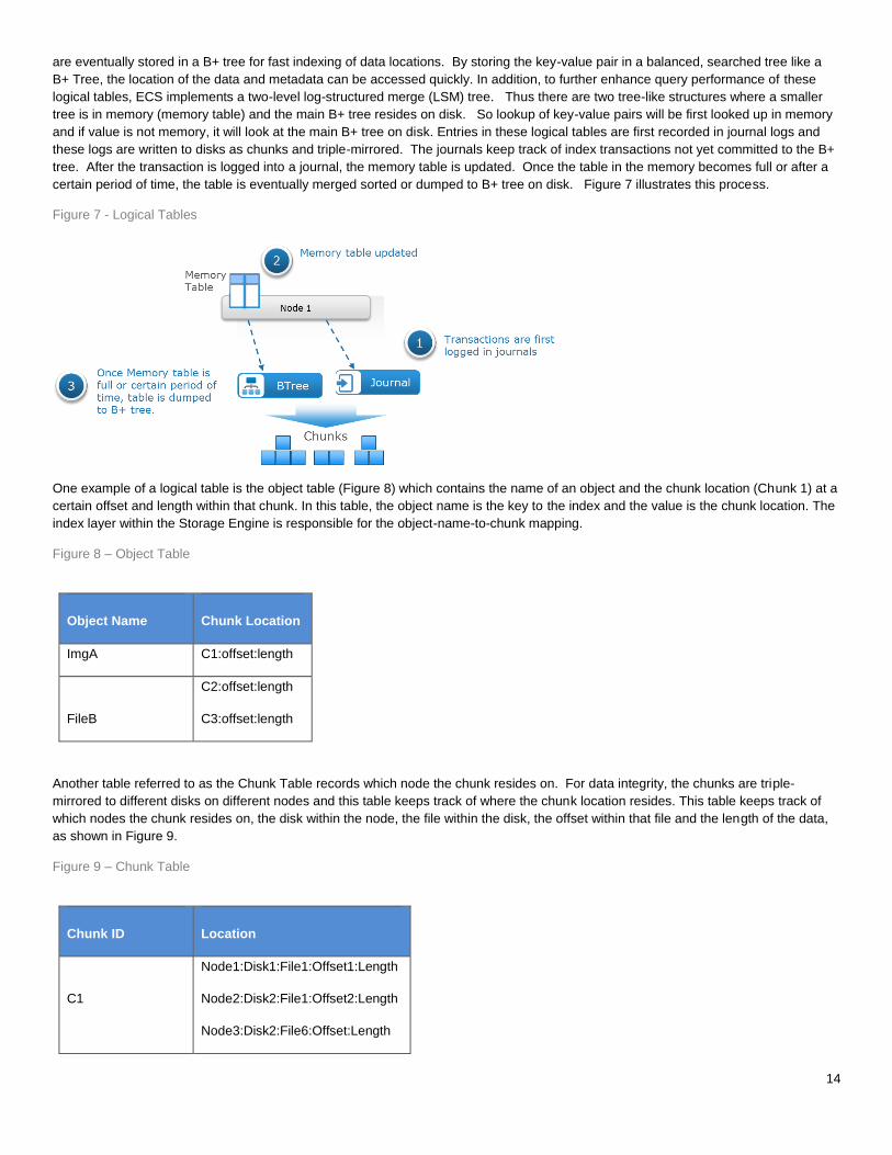
certain period of time, the table is eventually merged sorted or dumped to B+ tree on disk. Figure 7 illustrates this process.
Figure 7 - Logical Tables
One example of a logical table is the object table (Figure 8) which contains the name of an object and the chunk location (Chunk 1) at a
certain offset and length within that chunk. In this table, the object name is the key to the index and the value is the chunk location. The
index layer within the Storage Engine is responsible for the object-name-to-chunk mapping.
Figure 8 – Object Table
Object Name Chunk Location
ImgA C1:offset:length
FileB
C2:offset:length
C3:offset:length
Another table referred to as the Chunk Table records which node the chunk resides on. For data integrity, the chunks are triple-
mirrored to different disks on different nodes and this table keeps track of where the chunk location resides. This table keeps track of
which nodes the chunk resides on, the disk within the node, the file within the disk, the offset within that file and the length of the data,
as shown in Figure 9.
Figure 9 – Chunk Table
Chunk ID Location
C1
Node1:Disk1:File1:Offset1:Length
Node2:Disk2:File1:Offset2:Length
Node3:Disk2:File6:Offset:Length

15
As mentioned previously, ECS was designed to be a distributed system such that storage and access of data are spread across the
nodes. Since these tables can get very large, these logical tables are divided into partitions and assigned to different nodes. The node
then becomes the owner of that partition or section of the table. So to get the location of a chunk would require retrieving the
information from the partition owner. A partition record table is illustrated in Figure 10 below.
Figure 10 - The Partition Records Table
Partition ID Owner
P1 Node 1
P2 Node 2
P3 Node 3
If the node goes down, another node takes ownership of the partition. The logical tables owned by the unavailable node get recreated
on a new node and that node becomes the partition owner. The table is recreated by using the B+ tree root stored on disk and
replaying the journals also stored on disk. As previously mentioned the B+ tree and journals are stored in chunks (just like data) and
are triple-mirrored. Figure 11 shows the failover of partition ownership.
Figure 11 - Failover of Partition Ownership
DATA FLOW
Data can be accessed by any of the ECS nodes and written to three different nodes (triple-mirrored) within ECS for data protection and
resiliency. Also, prior to writing data to disk, ECS runs a checksum function and stores the result; then data is evaluated for
compression. If in the first few bytes of data is compressible it will compress the data, otherwise it will not for performance. Similarly
with reads, data is decompressed and checksum is validated. The data flow of reads and writes are described below.
1. The data flow for writes is as follows (shown in Figure 12):
2. A create object is requested from client and is directed to one of the nodes (Node 1 in this case) who will process the request.
3. The data are written to a new chunk or appended to an existing chunk and triple-mirrored to three different nodes in parallel
(initiated by Node 1 in this example).
4. Once the three copies are acknowledged to have been written, an update to the logical tables (index) of partition owner occurs
with name and chunk location.
5. The partition owner of index (“Node 3” in this case) records this write transaction into the journal logs which is also written into
a chunk on disk and triple mirrored to three different nodes in parallel (initiated by Node 3).

16
6. Once the transaction has been recorded in the journal logs, an acknowledgement is sent to the client.
In a background process, journal entries are processed and persisted onto disk in B+ trees as chunks and triple-mirrored.
Figure 12 - Data Write Flow
The data flow for reads include the following (shown in Figure 13):
1. An object read request is received and directed to any available node to process. Node 1 in this example.
2. As mentioned in the Data Management section of this paper, there are logical tables (key-value pairs) containing information
to the location of the object, like object table and chunk table. These tables are partitioned and are distributed among the
nodes to own and manage. So, object request will be processed by Node 1 in this case. Node 1 will utilize a hash function
using the object name ID to determine which node is the partition owner of the logical table where this object information
resides. In this example, Node 2 is owner and thus Node 2 will do a lookup in the logical tables to get location of chunk. In
some cases, the lookup can occur on two different nodes, for instance when the location is not cached in logical tables of
Node 2.
3. From the previous step, location of chunk is provided to Node 1 who will then issue a byte offset read request to the node that
holds the data, Node 3 in this example, and will send data to Node 1.
4. Node 1 will send data to requesting client.
Figure 13 - Data Read Flow

17
BOX CARTING
ECS has a unique and inherent feature called box-carting which helps performance for data writes. Box-carting aggregates multiple
small data objects queued in memory and then write them in a single disk operation, up to 2MB of data. This improves performance by
reducing the number of roundtrips to process individual writes to storage. Figure 14 provides an illustration of box-carting.
Figure 14 - Box-Carting
As for writes of large objects, all nodes within ECS can process write requests for the same object simultaneously and write to different
set of disks, taking advantage of all the spindles in the ECS cluster. Thus, ECS can ingest and store small and large objects efficiently.
SPACE RECLAMATION
ECS writes data to chunks and, during updates and deletes, there will be blocks of data that are no longer referenced and used. In
ECS 3.0, space reclamation or garbage collection has been enhanced to not only reclaim space when a chunk is completely empty, but
also reclaim space when a chunk is partially empty. There are three approaches to space reclamation supported in ECS 3.0 and later
releases:
Normal Garbage Collection – when entire chunk is garbage, reclaim space.
Partial Garbage Collection by Merge – when chunk is 2/3 garbage, reclaim the chunk by merging the valid parts of chunk
with other partially filled chunks to a new chunk and reclaim the space.
Partial Garbage Collection with Compaction –when chunk is greater than 1/3 and less than 2/3 garbage, the valid parts of
the chunk are re-erasure coded to protect the valid data. This involves treating the garbage ranges within the chunk as zeros
for re-calculating the erasure code of the valid data. Once the valid data has been re-erasure coded the garbage ranges are
then eligible to be reclaimed.
If the chunk is replicated to another site within a replication group, utilize a mathematically XOR approach to replace the garbage space
at remote sites before the garbage chunk or chunk ranges are freed for re-use. This method requires an XOR encode of a garbage
chunk or a set of partial chunks whose garbage sum is equal to or greater than 128MB with a new chunk that is being shipped to same
site where the garbage ranges were replicated to; and then, XOR chunk again at remote site to replace the garbage ranges of the
chunk copies with the new chunk. Once this operation has been done, the garbage ranges are eligible to be reclaimed. This avoids the
extra WAN traffic specifically when there are 3 or more sites.
With the support of partial chunk reclamation, ECS provides better overall space utilization. Note that the XOR process done in partial
garbage collection should not be confused with the XOR approach used for storage efficiency in three or more sites. For detailed
description of the new space reclamation introduced in ECS 3.0, please refer to the ECS Garbage Collection Process Overview
whitepaper, internal only.
FABRIC
The Fabric layer provides clustering, system health, software management, configuration management, upgrade capabilities, and
alerting. It is responsible for keeping the services running and managing resources such as disks, containers, the firewall, and the

18
network. It tracks and reacts to environment changes such as failure detection and provides alerts related to system health. The fabric
layer has the following components to manage the overall system:
Node agent – manages host resources (disks, the network, containers, etc.) and system processes.
Lifecyle Manager – application lifecycle management which involves starting services, recovery, notification, and failure
detection.
Persistence Manager – provides the coordination and synchronization of the ECS distributed environment.
Registry – stores all the Docker images for ECS.
Event Library – holds the set of events occurring on the system.
Hardware Manager (HWMgr) – provides status, event information and provisioning of the hardware layer to higher level
services. These services have currently been integrated to the Fabric Agent to support industry standard hardware.
NODE AGENT
The node agent is a lightweight agent written in Java that runs natively on every ECS node. Its main duties include managing and
controlling host resources (Docker containers, disks, the firewall, the network), and monitoring system processes. Examples of
management include formatting and mounting disks, opening required ports, ensuring all processes are running, and determining public
and private network interfaces. It also has an event stream that provides ordered events to a lifecycle manager to indicate events
occurring on the system. A Fabric CLI allows you to diagnose issues and look at overall system state.
LIFE CYCLE MANAGER
The lifecycle manager runs on a subset of nodes (three to five instances) and manages the lifecycle of applications (object-main)
running on various nodes. Each lifecycle manager is responsible for tracking a number of nodes. Its main goal is to manage the entire
lifecycle of the ECS application from boot to deployment, including failure detection, recovery, notification and migration. It looks at the
node agent streams and drives the agent to handle the situation. When a node is down, it responds to failures or inconsistencies in the
state of the node by restoring the system to a known good state. If a lifecycle manager instance is down, another one takes its place if
available.
REGISTRY
The registry contains all the ECS Docker images used during installation, upgrade and node replacement. A Docker container called
fabric-registry runs on one node within the ECS rack and holds the repository of ECS Docker images and information required for
installations and upgrades. Although the registry is available on one node, all Docker images are locally cached on all nodes.
EVENT LIBRARY
The event library is used within the Fabric layer to expose the lifecycle and node agent event streams. Events generated by the system
are persisted onto shared memory and disk to provide historical information on the state and health of the ECS system. These ordered
event streams can be used to restore the system to a specific state by replaying the ordered events stored. Some examples of events
include node events such as started, stopped or degraded.
HARDWARE MANAGER (HWMGR)
The hardware manager has been integrated to the Fabric Agent in order to support industry standard hardware.
Its main purpose is to provide hardware specific status and event information, and provisioning of the hardware layer to higher level
services within ECS.
INFRASTRUCTURE
Each ECS node runs a specific operating system. ECS Appliance currently runs SuSE Linux Enterprise 12 which acts as the ECS
infrastructure. For the ECS software deployed on custom industry standard hardware the operating system can be RedHat Enterprise
Linux (RHEL) or CoreOS. Custom deployments are done via a formal request and validation process. Docker is also installed on the
infrastructure to deploy the encapsulated ECS layers described in the previous sections. Because ECS software is written in Java, the
Java Virtual Machine (JVM) is installed as part of the infrastructure.

19
DOCKER
ECS runs on top of the operating system as a Java application and is encapsulated within several Docker containers. The containers
are isolated but share the underlying operating system resources and hardware. Some parts of ECS software run on all nodes and
some run on one or some nodes. The components running within a Docker container include:
object-main – contains the resources and processes relating to the data services, storage engine, portal and provisioning
services. Runs on every node in ECS.
fabric-lifecycle – contains the processes, information and resources required for system-level monitoring, configuration
management and health management. Depending on the number of nodes in the system, there will be an odd number of
fabric-lifecycle instances running. For example, there will be three instances running on a four-node system and five instances
for an eight-node system.
fabric-zookeeper – centralized service for coordinating and synchronizing distributed processes, configuration information,
groups and naming services. It is referred to as the persistence manager and runs on odd number of nodes, for instance,
three for a four-node system and five for an eight –node system.
fabric-registry – location or registry of the ECS Docker images. Only one instance runs per ECS rack.
There are other processes and tools that run outside of a Docker container namely the Fabric node agent and hardware abstraction
layer tools. Figure 15 below provides an example of how ECS is run on a four node deployment.
Figure 15 - Docker Containers and Agents on Four Node Deployment Example
Figure 16 shows a view of the object-main container in one of the nodes of an ECS system. The listing provides the some of the
services running in the Docker container.
Figure 16 - Processes, resources, tools and binaries in object-main container

20
FILESYSTEM LAYOUT
ECS Each ECS node is directly connected to a set of commodity disks. Each disk is formatted and mounted as an XFS filesystem and
has a unique identifier (UUID). Data are stored in chunks and the chunks are stored in files within the filesystem. Each disk partition or
filesystem is filled with files that are 10GB in size. These files are created during installation such that contiguous blocks are allocated
for the files. The number of files within each disk depends on the disk size. For instance, a 1TB disk will have 100, 10GB files. The
names of the files inside the disk are “0000”, “0001”, “0002”, and so forth. Figure 17 provides a screenshot of the XFS filesystems and
10GB files populated on one node of the ECS system.
Figure 17- Mounted XFS and 10G Files Storing the Chunks
HARDWARE
ECS software can run on a turn-key Dell EMC appliance or on industry standard hardware. Flexible entry points exist with the ability to
rapidly scale to petabytes and exabytes of data. With minimal business impact, you can scale ECS linearly in both capacity and
performance by simply adding nodes and disks to your environment. The basic hardware required to run ECS includes a minimum of
four compute nodes with data disks, a pair of 10GbE switches for data, and a 1GbE management switch.
ECS APPLIANCE
The ECS appliance currently supports two generations of the U-Series model and a denser model, D-Series. This section will only
highlight the hardware components required to run ECS software. For additional documentation on installing and cabling ECS hardware
see the following documents:
Dell EMC ECS Product Documentation Index
– ECS Planning Guide
– ECS Hardware and Cabling Guide
– ECS System Administrator’s Guide
SolVe Desktop (Procedure Generator) which has information on Switch Configuration Files and Installing ECS Software
Guide. This link may require access to the Dell EMC support website.
Figures 18, 19, and 20 in the next sections provide a view of the current U-Series (Gen-1 and Gen-2) and D-Series models. Please
refer to the ECS Appliance Specification Sheet for more information on ECS models. The data sheets also contain information about
power requirements for each model.
U- Series
A standard U-Series appliance contains two 10GbE switches, one 1GbE switch, and four or eight x86 server nodes and disk array
enclosures (DAE). Each DAE is connected to one x86 Server by SAS; a four-server model has four disk array enclosures and an eight-
server model has 8 disk enclosures. For the U-Series, a DAE can have up to 60 disks.

21
Figure 18 - ECS Appliance Gen-1 Models
Figure 19 - ECS Appliance Gen-2 Models

22
D-Series
The D-series are the denser models and targeted for very large deployment and as a replacement for tape archives. The D-series offer
4.5 and 6.2 PB of max raw capacity options. It is also designed for energy efficiency. Configurations of the D-Series have a minimum
of eight x86 nodes and can hold up to 98 disks. It also has two 10GbE switches and one 1GbE switch. These configurations offer a
lower TCO comparable to tape. Minimum ECS 2.2.1 release is required for D-Series.
Figure 20- ECS Appliance D-Series Model
ECS Appliance Server Nodes
ECS can come with 1 to 4 blades in a 2U chassis as shown in Figure 21. Server specifications are as follows:
4 node blade in 2U with two CPUs per node
o Gen 1 - 2.4 GHz four-core Ivy Bridge (Phoenix Servers)
o Gen 2 and D-series – 2.4 GHz six-core Haswell CPUs (Rinjin Servers)
64GB memory per node
Dual 10Gb Ethernet (NIC-bonding makes them appear as a single port)
Dual 1Gb Ethernet
Dedicated 1Gb Ethernet remote diagnostics
4 x 2.5” drive slots per node
Single (1) 400GB SSD sysdisk
Single DOM for OS boot
Two SAS interfaces per node
23
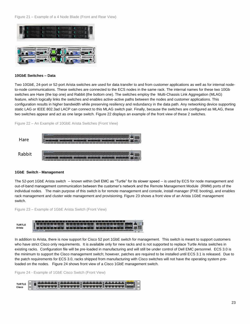
Figure 21 – Example of a 4 Node Blade (Front and Rear View)
10GbE Switches – Data
Two 10GbE, 24-port or 52-port Arista switches are used for data transfer to and from customer applications as well as for internal node-
to-node communications. These switches are connected to the ECS nodes in the same rack. The internal names for these two 10Gb
switches are Hare (the top one) and Rabbit (the bottom one). The switches employ the Multi-Chassis Link Aggregation (MLAG)
feature, which logically links the switches and enables active-active paths between the nodes and customer applications. This
configuration results in higher bandwidth while preserving resiliency and redundancy in the data path. Any networking device supporting
static LAG or IEEE 802.3ad LACP can connect to this MLAG switch pair. Finally, because the switches are configured as MLAG, these
two switches appear and act as one large switch. Figure 22 displays an example of the front view of these 2 switches.
1GbE Switch - Management
The 52-port 1GbE Arista switch -- known within Dell EMC as “Turtle” for its slower speed -- is used by ECS for node management and
out-of-band management communication between the customer’s network and the Remote Management Module (RMM) ports of the
individual nodes. The main purpose of this switch is for remote management and console, install manager (PXE booting), and enables
rack management and cluster wide management and provisioning. Figure 23 shows a front view of an Arista 1GbE management
switch.
Figure 23 – Example of 1GbE Arista Switch (Front View)
In addition to Arista, there is now support for Cisco 52 port 1GbE switch for management. This switch is meant to support customers
who have strict Cisco only requirements. It is available only for new racks and is not supported to replace Turtle Arista switches in
existing racks. Configuration file will be pre-loaded in manufacturing and will still be under control of Dell EMC personnel. ECS 3.0 is
the minimum to support the Cisco management switch; however, patches are required to be installed until ECS 3.1 is released. Due to
the patch requirements for ECS 3.0, racks shipped from manufacturing with Cisco switches will not have the operating system pre-
loaded on the nodes. Figure 24 shows front view of a Cisco 1GbE management switch.
Figure 24 - Example of 1GbE Cisco Switch (Front View)
Figure 22 – An Example of 10GbE Arista Switches (Front View)

24
Disk Array Enclosure (DAE)
For the U-Series, the DAEs are 4U enclosures that can have a maximum of 60 disks. Each DAE is connected to one server in the ECS
node by one (Gen-1) or two (Gen-2) 6GB/s SAS connection. Thus, there are four DAEs in a 4-node ECS rack, and eight DAEs in an 8-
node ECS rack. Currently, the supported drives are 6TB 7200 RPM SATA drives for Gen-1 and 8TB 7200 RPM SAS drives for Gen-2.
Each DAE for the U-Series includes a hot-swappable LCC. The LCC’s main function is to be a SAS expander and provide enclosure
services for all drive slots. The LCC independently monitors the environmental status of the entire enclosure and communicates the
status to the ECS Element Manager. Note that the LCC is a hot-swappable component, but it cannot be replaced non-disruptively. The
DAE has just one LCC, therefore, the disks in the DAE need to be brought offline before the LCC is replaced.
For the D-Series models, the DAEs are 4U enclosures that can have a maximum of 98 disks. It connects to one server in the ECS
node by two12 Gb/s SAS connection. It supports 8TB 7200 RPM drives for a maximum of 784TB per DAE. Entire chassis is “cold
serviceable” which means replacing the drives or I/O modules would require temporarily shutting down the entire DAE and placing the
node in maintenance mode.
ECS Node Connectivity
There are four nodes in a 2U blade server, and each node has one or two SAS connections to a DAE (depending on the hardware
generation used) and four network connections -- one link to each of the two 10GbE switches and two links to the 1GbE switch.
Each node has two 10GbE ports, which appear to the outside world as one port via NIC bonding. Each 10GbE port connects to one
port in the Hare switch and one port in the Rabbit switch . These public ports on the ECS nodes get their IP addresses from the
customer’s network, either statically or via a DHCP server.
The 1GbE management port in an node connects to an appropriate port in the 1GbE switch (Turtle) and has a private address of
192.168.219.X. Each node also has a connection between its RMM port and a port in the 1GbE switch, which in turn has access to a
customer’s network to provide out-of-band management of the nodes. To enable access for the RMM ports to the customer’s network,
Ports 49 and/or 50 in Turtle are linked to the customer’s network either directly or through the 10GbE top-of-the-rack switches. The
RMM port is used by Dell EMC field service personnel for monitoring, troubleshooting and installation.
Customer applications connect to ECS by using the (10GbE) public IP addresses of the ECS nodes.
You can expand an ECS rack by daisy-chaining one or more ECS racks to an existing rack. The 1GbE switches in the racks are used
for serially linking the racks. The 10GbE switches in each rack will be connected to a customer-provided switch or backplane. Thus the
data and chunk traffic will flow through the 10GbE network. For more detailed information on connectivity, please refer to the ECS
Hardware and Cabling Guide and other references stated earlier in this section. Figures 25 and 26, which depict the network cabling,
as well as the figures in the hardware section also appear in the ECS Hardware and Cabling Guide.
Figure 25 – Example of 10 GbE Network Cabling for 4 nodes

25
Figure 26 – Example of 1GbE Network Cabling for 4 nodes
Network Separation
In ECS 2.2.1 and later, there is support for segregating different types of network traffic for security and performance isolation. The
main types of traffic that can be separated include:
Management Traffic
Geo Replication Traffic
Data Traffic
There will be a new mode of operation called the “network separation mode”. When enabled during deployment, each node can be
configured at the operating system level with up to three IP addresses or logical networks for each of the different types of traffic. This
feature has been designed to provide the flexibility of either creating three separate logical networks for management, replication and
data or combining them to either create two logical networks, for instance management and replication traffic is in one logical network
and data traffic in another logical network. Network separation is currently only supported for new ECS installations.
ECS implementation of network separation requires each logical network traffic to be associated with particular services and ports. For
instance, the portal services communicate via ports 80 or 443, so these particular ports and services will be tied to the management
logical network. The table below highlights the services and some of the ports fixed to a particular type of logical network. For a
complete list of services associated with ports, refer to the ECS Security Configuration Guide.
Table 2 - Services associated with logical network.
Services (Ports) Logical Network
ECS Portal (ports 80 and 443), Provisioning , metering and management
API (ports 4443), ssh (ports 22)
Management Network
Data across NFS, Object (port 3218, ports 9021 thru 9025) and HDFS (port
9040)
Data network
Replication data, XOR (ports 9094-9098) Replication Network
ESRS (Dell EMC Secure Remote Services) Based on the network that the ESRS Gateway
is attached
DNS (port 53), NTP (port 123), AD (ports 389 and port 636), SMTP (port 25) Available on both data and management
network. At the minimum on the data network.

26
Network separation is achievable via logical using different IP addresses, virtual using different VLANs or physical using different
cables. The command ‘setrackinfo’ is used to configure the IP addresses and VLANs. Any switch-level or client-side VLAN
configuration is the customer’s responsibility. For physical network separation, customers would need to submit a Request for Product
Qualification (RPQ) by contacting Dell EMC Global Business Service (GBS). For more information on network separation configuration,
see the ECS Installation Guide in SolVe Desktop (Procedure Generator).
Upgrading ECS
You can upgrade ECS by adding extra disks to existing DAEs or adding nodes and DAEs. Depending on model, each DAE can store
maximum 60 or 98 disk drives, but disks are upgraded 5, 10, 15 or 28 per node at a time depending on model. Please refer to the ECS
Hardware and Cabling Guide for more information on the upgrade paths for each series of ECS. For the U400E and U480E models
recently introduced, upgrade support will be available on Q1 2017. Also, check with Dell EMC’s sales tools or representative to verify
what upgrades are possible for a given configuration.
ECS SOFTWARE ON INDUSTRY STANDARD HARDWARE
ECS software version 2.2.1 bundled with SLES 12 SP1, Docker, JVM and tools or later can be installed on Dell EMC-approved 3rd-
party industry standard hardware. There are two deployment offerings available:
Certified - ECS software running on certified hardware.
Custom – ECS software running on hardware, operating system and tools outside of certified matrix
The certified offering is targeted for customers needing small to large petabytes of object storage whereas custom is for big customer
deals requiring a significant amount in petabytes of object storage. The value of deploying ECS software on commercial off the shelf
hardware is that it reduces capital expense, prevents vendor lock-in and enables customers to build homogenous datacenter
infrastructure with unified commodity hardware. Table 3 describes minimum general requirements to use ECS software solution on
industry standard hardware.
Table 3 - Minimum Requirements
Type Requirement
ECS Software Bundle
Version 2.2.1 HF 1 or later bundled with SLES 12 SP1, Docker, JVM and related tools.
Server Nodes
5 nodes minimum
Single 8-core minimum CPU per node
64 GB memory per node
10 disks per node (nearline HDD)
Operating System Disk
Minimum 400 GB SSD**
Networking
10 GbE data (dual 10 GbE recommended)
1 Gbe management port (required)
Disk to Node Connectivity
HBA or HBA pass-thru mode recommended
No RAID controller or a RAID controller that supports JBOD mode. All disks need to be
in JBOD mode.

27
Monitoring
Integrate with Dell EMC ESRS for remote debugging/monitoring
**NOTE: For DSS 7000 only, the minimum is 120GB SSD due to current availability.
The same data and management Arista switches used in the ECS appliance are used with the industry standard hardware. Customers
are required to have engineering resources to install and manage the operating system and hardware.
Current hardware that has been certified with ECS Software Bundle is defined in Table 4. Reference Architecture papers are also
available for some of the certified hardware and can be downloaded or viewed from Dell EMC internal website, ECS FastPass.
Table 4 - Industry Standard Hardware Certified
Industry Standard Hardware Certified
HP Proliant SL4540 Gen 8
Dell R730XD
Dell DSS 7000
In order to setup ECS on certified hardware, use the Precheck Guide to verify your environment meets minimum requirements. Then
follow the standard ECS Appliance installation documentation to install the software. The Precheck Guide and the Installation Guides
are available through SolVe desktop. There is a Health and Troubleshooting guide also available in ECS Product Documentation to
assist with issues you may encounter.
Customers who would like to deploy ECS software on industry standard hardware can request for a quote via ASD Helpdesk. Custom
configurations would require approval from product management and a qualification process.
SUPPORT
Depending on whether you run ECS software on an ECS appliance or industry standard hardware, the support models differ. Table 5
describes the support model offered for each type of hardware deployment.
Table 5 - Software and Hardware Support
Type ECS Appliance Industry Standard
Hardware (Certified)
Industry Standard
Hardware (Custom)
Software Package ECS Software ECS Software v2.2.1 Hotfix 1
or later
ECS Software v2.2.1
Hotfix 1 or later
Operating System SLES 12 SP1
provided by Dell
EMC
SLES 12 SP1 Bundled with
ECS Software
Custom
Hardware Infrastructure Dell EMC
provided
hardware rack
Dell EMC certified and
approved hardware
Custom
Network Infrastructure Dell EMC
provides fully
Uses the same network
infrastructure as in Dell EMC
Custom

28
managed rack ECS appliance
Hardware Maintenance Dell EMC
Customer
Customer
Hardware Issue Resolution
Dell EMC
Customer
Customer
Operating System Patch Deployment and
Management
Dell EMC
Dell EMC
Customer
Operating System Issue Resolution
Dell EMC
Dell EMC
Customer
ECS Software Installation and Upgrade Using
ECS Tools
Dell EMC
Dell EMC
Dell EMC
ECS Storage Engine and Access Protocol –
Issue Resolution
Dell EMC
Dell EMC
Dell EMC
Service Reliability and Availability – Issue
Resolution
Dell EMC
Dell EMC
Dell EMC
Assistance With Other Storage Issues (e.g.
cluster expansion, disk replacement, etc.)
Dell EMC
Dell EMC
Dell EMC
SECURITY
ECS security is implemented at the administration, transport and data levels. User and administration authentication is achieved via
Active Directory, LDAP methods, Keystone, or within the ECS portal. Data level security is done via HTTPS for data in motion and/or
server-side encryption for data at rest.
AUTHENTICATION
ECS supports both Active Directory, LDAP and Keystone authentication methods to provide access to manage and configure ECS;
however, limitations exist as shown in Table 6. For more information on security, see the ECS Security Configuration Guide.
Table 6 - Authentication Methods
Authentication Method Supported
Active Directory
AD Groups are supported for management users
Supported for Object Users
Multi-domain is supported.
LDAP
LDAP Groups are not supported for management users
LDAP is supported for Object Users
Multi-domain is supported.
Keystone
RBAC policies not yet supported.
No support for un-scoped tokens
No support of multiple Keystone Servers per ECS system

29
DATA SERVICES AUTHENTICATION
Object access using RESTful APIs is secured over HTTPS via specific ports, depending on the protocol. All incoming requests are
authenticated using defined methods such as Hash-based Message Authentication Code (HMAC), Kerberos, or token authentication
methods. Table 7 below presents the different methods used for each protocol.
Table 7 - Data Services Authentication
Protocols Authentication Methods
Object
S3 V2/V4 HMAC-SHA1
Swift
Token – Keystone v2 and v3 (scoped, UUID, PKI tokens),
SWAuth v1
Atmos HMAC-SHA1
CAS Secret Key PEA file
HDFS Kerberos
NFS Kerberos , AUTH_SYS
DATA AT-REST-ENCRYPTION (D@RE)
ECS version 2.2 and later supports server-side encryption. Server-side encryption follows the FIPS-140-2 Level 1 compliance,
AES256 algorithm. Key features of ECS Data-at rest-encryption include:
Low touch encryption at rest – enabled easily through the ECS Portal
Namespace- and bucket-level control with transitivity – encryption can occur at namespace or bucket level
Automated key management
S3 encryption semantics support – Server Side Encryption (SSE) constructs can be used to allow object encryption, e.g. x-
amz-server-side-encryption.
A valid license is required to enable server-side encryption via the ECS Portal or through the ECS REST API. Each namespace, bucket and object has an associated key that is auto-generated at the time of creation. Only data and user-defined metadata will be encrypted inline prior to being stored on disks.
Key Management
Encryption can be enabled at the namespace, bucket and/or object levels. There are two types of keys:
User provided keys via S3 Header – key is provided by user through the header in the S3 API
System-generated keys – randomly generated and hierarchically structured
For S3 users and applications using the S3 REST APIs, object-level encryption can be done by either system-generated or user-
specified keys. If the S3 encryption header provides the key, then encryption of object is done using the user-provided key. ECS
validates the key provided for updates, appends, and reads is the same as the key used for object creation. If the encryption header is
provided without a key, then the system-generated keys are used to encrypt the data.
System-generated keys at each level are auto-generated and encrypted using the key of its immediate parent. The master key is
encrypted by utilizing asymmetric public-private encryption. The public and private keys are used to encrypt and decrypt the master
key. Keys are generated and encrypted in a hierarchical order:
Public-Private Key pair – a pair of public-private keys generated for each ECS system. The private key is stored in the
system root disk of the node and the public key is stored with the master key on the ECS commodity disks.
Master Key – randomly generated key encrypted using the public key.
Namespace Key – randomly generated namespace key encrypted using the master key.
Bucket Key – randomly generated bucket key encrypted using the namespace key.
Object Key – randomly generated object key encrypted using the bucket key and object id.

30
The private key for decryption of master key is stored on system disks (managed by vNest) and the other encrypted keys are stored in
logical tables and in chunks, similar to data. They are also triple-mirrored, like data. When an object read or write request comes in, the
node servicing the request traverses the key hierarchy to encrypt or decrypt the object. It uses the private key that’s common to all
nodes to decrypt the master key. Figure 27 provides a pictorial view of the key hierarchy.
Figure 27 - Data Encryption using System Generated Keys
In a geo-replicated environment, when a new ECS system joins an existing system (referred to as a federation), the master key is
extracted using the public-private key of the existing system and encrypted using the new public-private key pair generated from the
new system that joined the federation. From this point on, the master key is global and known to both systems within the federation. In
Figure 28, the ECS system labeled VDC 2 joins the federation and the master key of VDC 1 (the existing system) is extracted and
passed to VDC 2 for encryption with the public-private key randomly generated by VDC 2.
Figure 28 - Encryption of Master Key in Geo Replicated Environment.
DATA INTEGRITY AND PROTECTION
The most common approach for data protection within storage systems is RAID. ECS, however, does not utilize RAID; it employs a
hybrid of triple mirroring of data, meta-data, and index and also erasure coding of data for enhanced data protection and reduction of
storage overhead. For data integrity, ECS utilizes checksums.

31
TRIPLE-MIRRORED
All types of information relating to objects, such as data, metadata, and index (B+ tree and journal logs) are written to chunks. At
ingest, the chunks are triple mirrored to three different nodes within the ECS system as shown in Figure 29. This technique of triple
mirroring allows for data protection of the data in case of a node or disk failure. For data chunks, one of the triple mirror copies is
erasure coded in place for performance.
Figure 29 - Triple Mirroring of Chunks
ERASURE CODING
Erasure coding provides enhanced data protection from a disk or node failure in a storage efficient fashion compared with conventional
protection schemes. The ECS storage engine implements the Reed Solomon 12+4 erasure-coding scheme, in which a chunk is broken
into 12 data fragments and 4 coding (parity) fragments. The resulting 16 fragments are dispersed across nodes at the local site. The
data and coding fragments of each chunk are equally distributed across nodes in the cluster. For example, with 8 nodes, each node has
2 fragments (out of 16 total). The storage engine can reconstruct a chunk from any 12 of the 16 fragments. ECS 2.2 and later includes
a cold archive option, for which a 10+2 erasure coding scheme is used. In this protection scheme, each chunk is broken into 10 data
fragments and 2 coding (parity) fragments, which allows for better storage efficiencies for particular use cases.
All data in ECS is erasure coded except the index and system metadata. The index provides location to objects and chunks and is
frequently accessed; hence, it is always kept in triple-mirrored chunks for protection.
ECS requires a minimum of four nodes to be able to conduct erasure coding and six nodes for the cold archive option, in which a 10+2
scheme is used instead of 12+4. Erasure coding stops when one node goes down in a four node cluster. When a chunk is full (128MB)
or after a set period of time, it’s sealed and erasure-coded. Erasure coding is conducted as a background process. After erasure
coding completes, the mirrored copies are discarded and a single erasure coded copy persists. In the erasure-coded copy, the original
chunk data remains as a single copy that consists of 16 data fragments dispersed throughout the cluster, i.e., ECS can read that chunk
directly without any decoding or reconstruction. For small objects, ECS doesn’t need to read all the fragments of the data -- it can
directly read the object from the fragment which contains it. ECS only uses the code fragments for chunk reconstruction when a failure
occurs. For objects greater than 128MB in size, erasure coding is done in-line and erasure-coded data is directly written to the disk.
This is done to enhance performance and decrease disk usage. Figure 30 gives a view of how a triple mirrored chunk is replaced by an
erasure coded chunk.
Figure 30 – Mirrored Chunks Replaced by Erasure Coding

32
In ECS 2.2 and later, when additional nodes are added into a configuration to upgrade capacity, ECS re-distributes erasure-coded
chunks in the background. This will have minimal impact on system performance; however, there will be an increase in inter-node
traffic during rebalancing. Redistribution enhances local protection by leveraging all of the resources within the infrastructure.
CHECKSUMS
Another mechanism ECS uses to ensure data integrity is to store the checksum for data written. Checksums are done per write-unit, up
to 2 MB. So, checksums can occur for one object fragment for large object writes or on a per-object basis for small object writes of less
than 2MB. During write operations, the checksum is calculated in memory and then written to disk. On reads, data is read along with
the checksum, and then the checksum is calculated in memory from the data read and compared with the checksum stored in disk to
determine data integrity. Also, the storage engine runs a consistency checker periodically in the background and does checksum
verification over the entire data set.
COMPLIANCE
To meet corporate and industry compliance requirements (SEC Rule 18a-4f) for storage of data, ECS implemented the following
components:
Platform hardening – addresses security vulnerabilities in ECS such as platform lockdown to disable access to nodes or
cluster, all non-essential ports (e.g. ftpd, sshd) are closed, full audit logging for sudo commands and support for ESRS(Dell
EMC Secure Remote services) to shut down all remote access to nodes.
Compliance Reporting – a system agent that reports system’s compliance status such as “Good” indicating compliance or
“Bad” indicating non-compliance.
Policy Based record retention and rules – limiting the ability to change records or data under retention using retention policies,
time-period and rules.
Advanced Retention Management (ARM) – to meet Centera compliance requirements additional retention rules were defined
for CAS only.
o Event Based Retention – enables application to specify retention period that will start when a specified event occurs
o Litigation Hold – enables application to temporarily prevent deletion of an object that is subject to an investigation or
legal action.
o Min/Max Governor – enables system administrator to specify a minimum and maximum value for the default retention
period on a per bucket basis.
Compliance is enabled at the namespace level and retention periods at the bucket level. Since compliance requirements certify the
platform, the compliance feature is available for ECS Appliance only. For information on enabling and configuring of compliance in
ECS please refer to the Data Access Guide and ECS System Administrator’s Guide.
DEPLOYMENT
ECS can be deployed as a single site or in a multi-site configuration. The building blocks of an ECS deployment include:
Virtual Data Center (VDC) – a geographical location defined as a single ECS deployment within a site. Multiple VDCs can be
managed as a unit.
Storage Pool – a storage pool can be thought of as a subset of nodes and its associated storage belonging to a VDC. An ECS node can belong to only one storage pool; a storage pool can have any number of nodes, the minimum being four. A storage pool can be used as a tool for physically separating data belonging to different applications.
Replication Group – defines where storage pool content is protected and locations from which data can be read or written.
Local replication groups protect objects within the same VDC against disk or node failures. Global replication groups span
multiple VDCs and protect objects against disk, node, and site failures.
Namespace - a namespace, which is conceptually the same as a “tenant,” is a logical construct. The key characteristic of a
namespace is that users from one namespace cannot access objects belonging to another namespace. Namespaces can
represent a department within an organization or a group within a department.

33
Buckets – container for object data. Buckets are created in a namespace to give applications access to data stored within
ECS. In S3, these containers are called “buckets” and this term has been adopted by ECS. In Atmos, the equivalent of a
bucket is a “subtenant”; in Swift, the equivalent of a bucket is a “container”, and for CAS, a bucket is a “CAS pool”. Buckets are
global resources in ECS. Where the replication group spans multiple sites, a bucket is similarly replicated across sites.
In order to be able to deploy ECS, certain infrastructure requirements need to be reachable by the ECS system.
Authentication Providers – users (system admin, namespace admin and object users) can be authenticated using Active
Directory or LDAP or Keystone
DNS Server – Domain Name server or forwarder
NTP Server – Network Time Protocol server. Please refer to the NTP best practices for guidance on optimum configuration
SMTP Server – (optional) Simple Mail Transfer Protocol Server is used for sending alerts and reporting from the ECS rack.
DHCP server – only if assigning IP addresses via DHCP
Load Balancer - (optional but highly recommended) evenly distributes loads across all data services nodes. Load balancers
can use simple algorithms such as random choice or round robin. More sophisticated load balancers may take additional
factors into account, such as a server's reported load, response times, up/down status, number of active connections,
geographic location and so on. The customer is responsible for implementing load balancers; customers have several options
including Manual IP allocation, DNS Round Robin, Client-Side Load Balancing, Load Balancer Appliances, and Geographic
Load Balancers. The following are brief descriptions of each of those methods:
Manual IP Allocation - Data node IP addresses are manually distributed to applications. This is not
recommended because it does not evenly distribute loads between the nodes and does not provide any fault-
tolerance if a node fails.
DNS Round-Robin - With DNS Round-Robin, a DNS name is created for ECS and includes all of the IP
addresses for the data nodes. The DNS server will randomly return the IP addresses when queried and provide
some pseudo-load balancing. This generally does not provide fault-tolerance because you would need to remove
the IP addresses from DNS to keep them out of rotation. Even after removing them, there is generally some TTL
(time-to-live) issues where there is a delay to propagate the removal. Also, some operating systems like
Windows will cache DNS lookups and can cause "stickiness," where a client keeps binding to the same IP
address, reducing the amount of load distribution to the data nodes.
Physical or Virtual load balancing- This option is the most common approach to load balancing. In this mode,
an appliance (hardware or software) receives the HTTP request and forwards it on to the data nodes. The
appliance keeps track of the state of all of the data nodes (up/down, # of connections) and can intelligently
distribute load amongst the nodes. Generally, the appliance will proactively "health check" the node (e.g.
GET/?ping on the S3 head) to ensure the node is up and available. If the node becomes unavailable it will
immediately be removed from rotation until it passes a health check. Another advantage to this kind of load
balancing is SSL termination. You can install the SSL certificate on the load balancer and have the load balancer
handle the SSL negotiation. The connection between the load balancer and the data node is then unencrypted.
This reduces the load on the data nodes because they do not have to handle the CPU-intensive task of SSL
negotiation.
Geographic load balancing - Geographic load balancing takes Physical or Virtual Load Balancing one step
further: it adds load balancing into the DNS infrastructure. When the DNS lookups occur, they are routed via an
"NS" record in DNS to delegate the lookups to a load balancing appliance like the Riverbed SteelApp. The load
balancer can then use Geo-IP or some other mechanism to determine which site to route the client to. If a site is
detected to be down, the site can be removed quickly from DNS and traffic will be routed to surviving sites
SINGLE-SITE DEPLOYMENT
In a single site, storage pools are defined, then the Virtual Data Center (VDC) is created with namespaces and buckets. Figure 31
shows one storage pool in a VDC with two namespaces each containing two buckets.
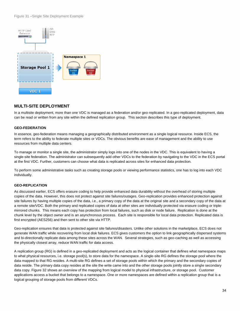
34
Figure 31 –Single Site Deployment Example
MULTI-SITE DEPLOYMENT
In a multisite deployment, more than one VDC is managed as a federation and/or geo-replicated. In a geo-replicated deployment, data
can be read or written from any site within the defined replication group. This section describes this type of deployment.
GEO-FEDERATION
In essence, geo-federation means managing a geographically distributed environment as a single logical resource. Inside ECS, the
term refers to the ability to federate multiple sites or VDCs. The obvious benefits are ease of management and the ability to use
resources from multiple data centers.
To manage or monitor a single site, the administrator simply logs into one of the nodes in the VDC. This is equivalent to having a
single-site federation. The administrator can subsequently add other VDCs to the federation by navigating to the VDC in the ECS portal
at the first VDC. Further, customers can choose what data is replicated across sites for enhanced data protection.
To perform some administrative tasks such as creating storage pools or viewing performance statistics, one has to log into each VDC
individually.
GEO-REPLICATION
As discussed earlier, ECS offers erasure coding to help provide enhanced data durability without the overhead of storing multiple
copies of the data. However, this does not protect against site failures/outages. Geo-replication provides enhanced protection against
site failures by having multiple copies of the data, i.e., a primary copy of the data at the original site and a secondary copy of the data at
a remote site/VDC. Both the primary and replicated copies of data at other sites are individually protected via erasure coding or triple-
mirrored chunks. This means each copy has protection from local failures, such as disk or node failure. Replication is done at the
chunk level by the object owner and is an asynchronous process. Each site is responsible for local data protection. Replicated data is
first encrypted (AES256) and then sent to other site via HTTP.
Geo-replication ensures that data is protected against site failures/disasters. Unlike other solutions in the marketplace, ECS does not
generate WAN traffic while recovering from local disk failures. ECS gives customers the option to link geographically dispersed systems
and bi-directionally replicate data among these sites across the WAN. Several strategies, such as geo-caching as well as accessing
the physically closest array, reduce WAN traffic for data access.
A replication group (RG) is defined in a geo-replicated deployment and acts as the logical container that defines what namespace maps
to what physical resources, i.e. storage pool(s), to store data for the namespace. A single-site RG defines the storage pool where the
data mapped to that RG resides. A multi-site RG defines a set of storage pools within which the primary and the secondary copies of
data reside. The primary data copy resides at the site the write came into and the other storage pools jointly store a single secondary
data copy. Figure 32 shows an overview of the mapping from logical model to physical infrastructure, or storage pool. Customer
applications access a bucket that belongs to a namespace. One or more namespaces are defined within a replication group that is a
logical grouping of storage pools from different VDCs.

35
Figure 32 - Geo Replicated Environment Example
ACTIVE-ACTIVE ACCESS
One key feature of ECS is the ability to read and write data from any VDC within a replication group. In ECS, data is replicated
asynchronously to multiple VDCs within a replication group. The challenge this poses is consistency of data across sites or VDCs. ECS
ensures strong consistency by fetching the metadata from the VDC that created the object data. Thus, if an object is created in site 1
and is read from site 2, ECS checks with site 1, who is the object owner, and validates that the copy replicated at site 2 is the latest
version of the data. If not, it fetches the data from site 1; otherwise, it uses the data from site 2.
The data flow of reads in a geo-replicated environment illustrated in Figure 33 below is as follows:
1. Site 2 does a read request. In this example, Site 1 is the object owner. The object owner is the site who first created object.
2. Read would require checking meta data from object owner to validate if Site 2 has the latest copy of data.
3. If not, then Site 1 will send the data to Site 2
4. Data sent to client.
Figure 33 - Read Data Flow in Geo Replicated Environment

36
The data flow of writes in a geo-replicated environment in which two sites are updating the same object is shown in Figure 34 and
described below. In this example, Site 1 created object first and becomes object owner. The data is mirrored or erasure coded and
journal is written as usual to local site.
1. Site 2 updates the same file. Site 2, first writes data locally (data mirrored or erasure coded locally)
2. Site 2 synchronously updates the metadata (journal write) to object owner, Site 1 and waits for acknowledgement of metadata
update from site 1.
3. Site 1 acknowledges the metadata write to Site 2.
4. Site 2 acknowledges the write to client.
NOTE: Site 2 will asynchronously replicate the chunk to site 1 (owning site) as usual. If the data is not yet replicated to owning site and
owning site wants to read the data, then it will get it from the remote site.
Figure 34 - Update of Same Object Data Flow in Geo-replicated environment.
In both read and write scenarios in a geo-replicated environment, there is latency involved in reading or updating the metadata from
object owner and retrieving data from object owner during a request.
GEO-CACHING
Customers with multi-site access patterns, specifically a replication group composed of three or more sites, could experience slow
performance if data is always fetched from primary site, i.e., where the data was originally written. Consider a geo-federated
environment with Sites 1, 2 and 3. An object, Object A, is written to Site 1 and the secondary copy of the object resides at Site 2. In this
scenario, a read for the object at Site 3 needs to fetch the object data from either Site 1 or Site 2 to honor the read. This leads to
elongated response times, especially in environments with multi-site access patterns. ECS alleviates the response time impact by using
some pre-designated percentage of disk space to cache objects that do not exist locally. For frequently accessed objects you would
see a reduced response time after the initial copy of the object is cached locally. The cache is an LRU implementation and cache size is
adjusted when nodes/disks are added to the storage pool.
TEMPORARY SITE OUTAGE (ACCESS DURING OUTAGE)
Temporary site failure refers to either a failure of the WAN connection between two sites or a failure of an entire site (such as a natural
disaster or power failure). ECS can detect and automatically handle any such temporary site failures. VDCs in a geo-replicated
environment establish a heartbeat mechanism. Sustained loss of heartbeats for a preset duration is indicative of a network outage and
the system adjusts its behavior accordingly. Without the TSO (Temporary Site Outage) functionality, the inability to communicate with
the node that owns the object (from a metadata perspective) leads to the system rejecting the read and write requests for the object.
This TSO feature aligns with the principle of strong consistency that the ECS system adheres to.

37
With “Access During Outage” enabled on a bucket and upon detecting a temporary outage, the system reverts to an eventual
consistency model, i.e., reads/writes from a secondary (non-owner) site are accepted and honored. Further, a write to a secondary site
during a network outage causes the secondary site to take ownership of the object. This allows each VDC to continue to read and write
objects from buckets in a shared namespace. Finally, the new version of the object becomes the authoritative version of the object
during reconciliation even if another application updates the object on the “owner” VDC.
Although many object operations continue during a network outage, certain operations are not be permitted, such as creating new
buckets, namespaces, or users.
When network connectivity between two VDCs is restored, the heartbeat mechanism automatically detects connectivity, restores
service and reconciles objects from the two VDCs. If the same object is updated on both VDC A and VDC B, the copy on the “non-
owner” VDC is the authoritative copy. So, if an object that is owned by VDC B is updated on both VDC A and VDC B during
synchronization, the copy on VDC A will be the authoritative copy that is kept, and the other copy will be overwritten. Table 8 and 9
capture the list of operations permitted in different system states for 2 and 3 sites.
Table 8 - Temporary Site Outage (Access During Outage for 2 Sites)
System State Description
Supported Operations (Primary | Secondary) Consistency
Read Object; Create Object; List Objects In Bucket
Update Object List Buckets in Namespace
Create and Edit Bucket, User, or Namespace
P S P S P S P S
Normal All zones connected
√ √ √ √ √ √ √ √ Strong
Temp Site Failover System detects temp site outage and completes temp site failover √ √ √ AO √ AO √ LB √ LB X X
Concurrent writes transition system to
eventual consistency
Site Rejoin Resume normal operation after resync; Objects/Buckets updated at both sites are reconciled with the state on secondary as the final version.
√ √ √ √ √ √ √ √ Strong
√ AO: Acquires Object Ownership √ LB: Locally Owned Buckets
Table 9 - Temporary Site Outage (Access During Outage for 3 Sites: Site 2 and Site 3 takes object ownership during an update)
System State Supported Operations (Site 1 | Site 2 | Site 3) Consistency
Read Object Update Object Create Objects; List Objects in Bucket
List Buckets in namespace
Create and Edit Bucket, Namespace or User

38
S1 S2 S3 S1 S2 S3 S1 S2 S3 S1 S2 S3 S1 S2 S3
Normal All zones connected √ √ √ √ √ √ √ √ √ √ √ √ √ √ √ Strong
Temp Site Failover System detects temp site outage and completes temp site failover
√ LO
√
√
√ LO
√ AO
√ AO
√ LB
√
√
√ LB
√ LB √ S3
√ LB √ S2
X X X Eventual Consistency
Site Rejoin Resume normal operation after resync; Objects/Buckets updated at both sites are reconciled with the state of non-owner as the final version
√ √ √ √ √ √ √ √ √ √ √ √ √ √ √ Strong
√ AO: Acquires Object Ownership √ LB: Locally Owned Buckets √ LO: Locally Owned Objects
When more than two VDCs are part of a replication group, and if network connectivity is interrupted between one VDC and the other
two, then write/update/ownership operations continue just as they would with two VDCS; however, the process for responding to read
requests is more complex, as described below.
If an application requests an object that is owned by a VDC that is not reachable, ECS sends the request to the VDC with the
secondary copy of the object. However, the secondary site copy might have been subject to a data contraction operation, which is an
XOR between two different data sets that produces a new data set. Therefore, the secondary site VDC must first retrieve the chunks of
the object included in the original XOR operation and it must XOR those chunks with the “recovery” copy. This operation will return the
contents of the chunk originally stored on the failed VDC. The chunks from the recovered object can then be reassembled and returned.
When the chunks are reconstructed, they are also cached so that the VDC can respond more quickly to subsequent requests. Note
reconstruction is time consuming. More VDCs in a replication group imply more chunks that must be retrieved from other VDC’s, and
hence reconstructing the object takes longer.
If a disaster occurs, an entire VDC can become unrecoverable. ECS treats the unrecoverable VDC as a temporary site failure. If the
failure is permanent, the system administrator must permanently failover the VDC from the federation to initiate fail over processing,
which initiates resynchronization and re-protection of the objects stored on the failed VDC. The recovery tasks run as a background
process. You can review the recovery process in the ECS Portal.
If ADO is not enabled, then to maintain strong consistency, the data in the zone which has the temporary outage is not available for
access from other zones. Object operations of read, create, and update as well as list buckets is not owned by the site, will fail. Also,
operations of create and edit of bucket, user and namespace will also fail.
FAILURE TOLERANCE
In a single site or geo configuration, there are several types of failures that can be tolerated before ECS is no longer accessible or able
to serve data. Node failures can be categorized into two types. The first type is that nodes fail one by one and when a second node
fails the recovery for data related with the previous failed node has finished. The second type is nodes fail almost at the same time, or a
node fails before recovery for previous failed node finishes. The impact of the failure depends on which node(s) goes done. Table 10
describes the best case scenario for failure tolerances of single site based on EC Scheme and number of nodes. In worst case
scenarios, specifically, for three and greater number of nodes failures and depending on which nodes go down, read, write, and erasure
coding can stop. Table 11 highlights the failures tolerated in a multi-site deployment.

39
Table 10- Best Case Scenario of Single Site Failure Tolerance Based on EC-Scheme
LEGEND
Erasure Coding Runs Read Write
Subset of Read Fails Subset of Writes Fails
Erasure Coding Stops Read Stops Write Stops
EC scheme Nodes in VDC Concurrent Failure at roughly same
time
One-by-one Failure (assume there is
enough free capacity to do all the
necessary data recovery)
12+4
4 nodes
# Failed Nodes Status # Failed Nodes Status
1
1
2
2
3
3
5 nodes
1
1
2
2
3-4
3-4
6 nodes
1
1
2
2
3
3
4-5
4-5
8 nodes
1-2
1-2
3-4
3-4
5-6
5
7
6-7
10+2
6 nodes
1
1
2
2
3
3
4-5
4-5
8 nodes
1
1
2
2
3
3-5
4-7
6-7
12 nodes 1-2
1-2
3-6
3-6
7-9 7-9
10
10

40
Table 11 - Multi-Site Failure Tolerance
Failure Model Tolerance
Geo-Replicated Failure 1 Site Failure
Temporary Site Failure When filesystem is enabled, read-only access
to files/HDFS and any other object protocols.
STORAGE EFFICIENCY
ECS uses erasure coding for data protection. Although this is more storage efficient than other forms of protection, such as mirroring, it
does incur some storage overhead. ECS provides a mechanism in which storage efficiency increases as three or more sites are used.
In a geo-replicated setup with multiple sites/ VDCs, ECS replicates chunks from the primary VDC to a remote site in order to provide
high availability. However, this simple replication can lead to a large overhead of disk space. To prevent this, ECS uses a smart
technique to reduce overhead while preserving high availability features. This can be illustrated with a simple example. Consider 3
VDC’s in a multi-site environment - VDC1, VDC2 and VDC3, and that VDC1 has chunk C1 and VDC2 has chunk C2. With simple
replication, a secondary copy of C1 and a secondary copy of C2 may be placed in VDC3. Since all chunks are of the same size, this will
result in a total of 4 x 128MB of space being used to store 2 x 128MB of objects.
In this situation ECS can perform an XOR operation of C1 and C2 (mathematically, written as C1 ⊕ C2) and place it in VDC3 and get
rid of individual secondary copies of C1 and C2. Thus, rather than using 2 x 128MB of space in VDC3, ECS now uses only 128MB (the
XOR operation results in a new chunk of the same size).
In this case, if VDC1 goes down, ECS can reconstruct C1 by using C2 from VDC2 and the (C1 ⊕ C2) data from VDC3. Similarly, if
VDC2 goes down, ECS can reconstruct C2 by using C1 from VDC1 and the (C1 ⊕ C2) data from VDC3.
Counterintuitively, as the number of linked sites increase, the ECS algorithm is more efficient in reducing the overhead. Table 12
provides information on the storage overhead based on the number of sites for normal erasure coding of 12+4 and cold archive erasure
coding of 10+2, and it illustrates how ECS becomes more storage efficient as more sites are linked. To obtain the lower overhead, the
same amount of data must be written at each site.
Table 12 - Storage Overhead
Number of Sites in
Replication Group
Default Use Case
(Erasure Code: 12+4)
Cold Archive Use Case
(Erasure Code: 10+2)
1 1.33 1.2
2 2.67 2.4
3 2.00 1.8
4 1.77 1.6
5 1.67 1.5
6 1.60 1.44
7 1.55 1.40

41
8 1.52 1.37
In some scenarios, replication may be desired on all sites for increased data protection and enhanced read performance. Enabling this
feature would disable the XOR capability for storage efficiency just described. Replication in all sites is available in ECS 2.2 and later.
CONNECTORS AND GATEWAYS
Several third-party software products have the capability to access ECS object storage. Independent Software Vendors (ISVs) such as
Panzura, Ctera, and Syncplicity create a layer of services that offer client access to ECS object storage via traditional protocols, such
as CIFS, NFS, and/or iSCSI. For more information on ISV products and use cases, see ECS Appliance Ecosystem Partners. You can
also access or upload data to ECS storage with Dell EMC products:
CloudArray - offers iSCSI or NAS services and can be used as a front-end to backup and archive data to ECS object storage
CloudPools- provides smart tiering of data to ECS object storage from Isilon.
CIFS-ECS Tool - an easy and simple tool to read and write data to ECS storage from a Windows platform.
CloudBoost – enables data protection workloads from Dell EMC Data Protection suite or Symantec NetBackup to move
deduplicated data to ECS.
Data Domain Cloud Tier – an automated native tiering of deduplicated data to ECS from Data Domain for long term retention.
It is a secure and cost-effective solution to encrypt data in the cloud with a reduced storage footprint and network bandwidth.
CONCLUSION
Private and hybrid clouds greatly interest customers, who are facing ever-increasing amounts of data and storage costs, particularly in
the public cloud space. ECS’s scale-out and geo-distributed architecture delivers an on-premise cloud platform that scales to exabytes
of data with a TCO (Total Cost of Ownership) that’s significantly less than public cloud storage. ECS is a great solution because of its
versatility, hyper-scalability, powerful features, and use of low-cost industry standard hardware.
REFERENCES
Links in this section may require login access to Dell EMC Support site or internal site.
ECS Technical Assets
– ECS Specification Sheet http://www.emc.com/collateral/specification-sheet/h13117-emc-ecs-appliance-ss.pdf
– ECS Datasheet https://www.emc.com/collateral/data-sheet/h13079-ecs-ds.pdf
– ECS Performance Whitepaper http://www.emc.com/collateral/white-papers/h14525-ecs-appliance-v2x-performance-wp.pdf
– Enabling Global Hadoop With Dell EMC Elastic Cloud Storage https://www.emc.com/collateral/white-papers/h44184-global-hadoop-ecs-wp.pdf
APIs and SDKs
– ECS Rest API http://www.emc.com/techpubs/api/ecs/v3-0-0-0/index.htm
– Dell EMC Data Services – Atmos and S3 SDK https://github.com/emcvipr/dataservices-sdk-java/releases
– Data Access Guide
https://support.emc.com/docu79368_ECS_3.0_Data_Access_Guide.pdf?language=en_US&language=en_US
Community
– ECS Community https://community.emc.com/community/products/vipr#developer
– ECS Test Drive https://portal.ecstestdrive.com/

42
– Object Browser Downloads S3 Browser - http://s3browser.com/download.aspx Cyberduck - https://sourceforge.net/projects/cyberduck/ Cyberduck ECS Profiles - https://community.emc.com/docs/DOC-27683
– ECS Appliance Ecosystem Partners https://community.emc.com/docs/DOC-38175
ECS Product Documentation
– ECS product documentation at support site or the community links:
https://support.emc.com/products/37254_ECS-Appliance-/Documentation/
https://community.emc.com/docs/DOC-53956
– SolVe Desktop (Procedure Generator)
https://solve.emc.com/desktopbinaries/setup.exe
Dell EMC ECS Connectors and Gateways
– CloudArray
https://www.emc.com/auth/rcoll/guide/h14675-ecs-cloudarray-solution-guide.pdf
– Cloud Pools
https://www.emc.com/auth/sp/guide/h14775-emc-ecs-cloudpools-solution-guide.pdf
– CIFS-ECS Tool
Whitepaper: https://www.emc.com/collateral/white-papers/h15277-emc-cifs-ecs-architecture-overview.pdf
Download site: https://download.emc.com/downloads/DL71660_CIFS-ECS-1.0-(64-bit).exe?source=OLS
– CloudBoost
https://www.emc.com/auth/rcoll/guide/h14694-ecs-cloudboost-solution-guide.pdf
– Data Domain Cloud Tier
https://inside.emc.com/docs/DOC-221354