Embed Size (px)
Citation preview

Copyright ©American Institute of Chemical Engineers 2018. All rights reserved.
1
SAChE® Certificate Program
Level 2, Course 4b: Explosion Hazards
Unit 5 – Explosion Prevention and Protection Techniques
Narration:
[No narration]

Copyright ©American Institute of Chemical Engineers 2018. All rights reserved.
2
Objectives
Narration (male voice):
This is the final unit in the Explosion Hazards course. By the end of this unit, titled “Explosion
Prevention and Protection Techniques,” you will be able to:
• Ask pertinent questions regarding explosion prevention and protection techniques
during the design of projects and periodic safety reviews of process systems;
• Suggest potential methods of explosion prevention and protection based on commonly
used approaches; and
• Locate common standards and guidelines on explosion prevention and protection.

Copyright ©American Institute of Chemical Engineers 2018. All rights reserved.
3
Introduction
Narration (male voice):
In this unit, we’re going to explore a number of topics:
• How to avoid the flammable region of the flammability diagram;
• How to avoid ignition sources;
• Explosion containment;
• Flammable vapors in piping systems;
• Vessel or equipment venting;
• Damage-limiting construction;
• Facility siting for explosions; and
• Standards and guidelines for explosion prevention and protection.

Copyright ©American Institute of Chemical Engineers 2018. All rights reserved.
4
SECTION 1: Avoiding the Flammable Region
Narration:
[No narration]

Copyright ©American Institute of Chemical Engineers 2018. All rights reserved.
5
Flammability Diagram
Narration (male voice):
In this first section, we’re going to focus on how to avoid the flammable region.
You may recall this flammability diagram from the SAChE Fire Hazards course. When dealing
with flammable materials, fire and explosions may be prevented by avoiding the flammable
zone shown in red in the diagram.

Copyright ©American Institute of Chemical Engineers 2018. All rights reserved.
6
Flammability Diagram (continued)
Narration (male voice):
By reducing the oxidant concentration, we can change the upper flammability limit (UFL) and in
turn reduce the flammable region. A reduction of oxidant concentration has little impact on the
lower flammability limit (LFL) until the oxidant concentration has almost reached the limiting
oxygen concentration (LOC).

Copyright ©American Institute of Chemical Engineers 2018. All rights reserved.
7
Vessel Purging Techniques
Narration (male voice):
This brings us to the topic of purging. Purging involves the use of an inert gas to sweep (or
replace) air or flammables out of lines or equipment.
Purging to replace the contents of a tank or vessel with inert can be accomplished in a number
of ways. Specific guidance on these methods is provided in the National Fire Protection
Association’s Standard 69 (NFPA 69).

Copyright ©American Institute of Chemical Engineers 2018. All rights reserved.
8
Operating Above UFL
Narration (male voice):
NFPA 69 permits operating systems above the UFL under specific conditions. The danger
associated with systems that operate above the UFL is the introduction of oxidants that could
generate a flammable mixture. This is a specific concern in systems that operate under negative
pressure where air may leak into the process. Please refer to NFPA 69 for guidance.

Copyright ©American Institute of Chemical Engineers 2018. All rights reserved.
9
SECTION 2: Avoiding Ignition Sources
Narration:
[No narration]

Copyright ©American Institute of Chemical Engineers 2018. All rights reserved.
10
Ignition Sources
Narration (male voice):
It is generally considered impractical to eliminate all possible ignition sources. However, that
doesn’t mean you shouldn’t mitigate all those that you can. In this section, we’ll discuss ways
you might mitigate ignition sources, including:
• Open flames;
• Combustion engines;
• Hot work;
• Hot surfaces;
• Smoldering; and
• Electrical and static discharges.

Copyright ©American Institute of Chemical Engineers 2018. All rights reserved.
11
Open Flames
Narration (male voice):
Flames may exist in a plant for production or heating purposes. For example, a plant may have a
thermal oxidizer or a boiler. It’s important that open flames from this equipment do not come in
contact with flammable solids, liquids or vapors. This means that this equipment should be
sufficiently enclosed and installed a safe distance from chemical storage and processing areas.

Copyright ©American Institute of Chemical Engineers 2018. All rights reserved.
12
Combustion Engines
Narration (male voice):
Combustion engines – such as those in cars, trucks, delivery vehicles, construction equipment,
and other machinery – should not be permitted to operate in areas where flammables are
expected to be present in the atmosphere.

Copyright ©American Institute of Chemical Engineers 2018. All rights reserved.
13
Hot Work
Narration (male voice):
Hot work – such as welding, cutting, drilling, grinding, and burning – can provide a source of
ignition for flammable or combustible materials. These activities can create sparks or ignition
sources for flammable vapors, combustible dusts, and other combustible materials.
Hot work is typically managed through close supervision, permitting, testing for flammable
atmospheres, and training. All hot work within a chemical processing facility should be carefully
controlled via a rigorous Safe Work Practices/Hot Work Permit system.

Copyright ©American Institute of Chemical Engineers 2018. All rights reserved.
14
Hot Surfaces
Narration (male voice):
Hot surfaces are found on heaters and dryers and other equipment. Bearings may heat beyond
the autoignition temperature (AIT) of liquids or dusts. Care must be taken to ensure that
flammables do not come in contact with hot surfaces.

Copyright ©American Institute of Chemical Engineers 2018. All rights reserved.
15
Smoldering
Narration (male voice):
Certain fuels can spontaneously combust. Before doing so, they will generally smolder; that is,
burn slowly with smoke but no flame. Smoldering hazards can be avoided by avoiding large piles
of combustibles. A tire fire is a classic example of a smoldering pile of combustibles that
spontaneously combusted.

Copyright ©American Institute of Chemical Engineers 2018. All rights reserved.
16
Electrical Discharges
Narration (male voice):
Electricity, including static discharge, has been the ignition source in many industrial fires and
explosions. Sources include electrically-operated machinery, switches, relays, and loose
connections in devices, such as meters or radios.

Copyright ©American Institute of Chemical Engineers 2018. All rights reserved.
17
Electrical Discharges (continued)
Narration (male voice):
Electrical ignition hazards can be controlled by following guidelines on Electrical Area
Classification, such as those in the National Electrical Code published by the National Fire
Protection Association. This code provides guidelines on the design of electrical equipment
within a classified area.
For example, electrical components may be required to be placed in sealed, pressurized, and/or
purged boxes to prevent flammables from coming in contact with potential sparks inside the
box.

Copyright ©American Institute of Chemical Engineers 2018. All rights reserved.
18
Static Discharges
Narration (male voice):
Static electric discharge has been the suspected source of ignition in many industrial accidents.
Static charge is generated when two different materials come into contact and then separate.
This results in an imbalance of electrical charge in the materials.
This can happen when fluids flow through a pipe, an aerosol forms, or a fluid is agitated in a
vessel. Incidents have most often been associated with the transfer of materials.

Copyright ©American Institute of Chemical Engineers 2018. All rights reserved.
19
Part 2

Copyright ©American Institute of Chemical Engineers 2018. All rights reserved.
20
Part 3

Copyright ©American Institute of Chemical Engineers 2018. All rights reserved.
21
Minimizing Risk of Static Electricity – Nonconductive Containers and
Materials
Narration (male voice):
To minimize risk of fire due to static discharge, avoid the use of nonconductive materials of
construction for the storage and transfer of flammables, including:
• Glass containers, vessels, pipes and liners; and
• Plastic containers, vessels, pipes, pumps and liners.

Copyright ©American Institute of Chemical Engineers 2018. All rights reserved.
22
Minimizing Risk of Static Electricity – Grounding and Bonding
Narration (male voice):
It’s also important to use grounding and bonding to maintain separate pieces of equipment at
the same electrical potential and to direct that potential to ground. Grounding refers to
connecting electrical equipment to the ground. Bonding refers to electrically connecting two
pieces of equipment.
On the next two slides, we’ll examine each of these in more detail.

Copyright ©American Institute of Chemical Engineers 2018. All rights reserved.
23
Grounding
Narration (male voice):
The voltage difference between two objects can be eliminated by connecting each to the
ground; this eliminates spark discharges (which are potential ignition sources) between the two
conductors.
Always ground all equipment containing flammables. This includes reactors, storage tanks,
drums, trucks and railcars.

Copyright ©American Institute of Chemical Engineers 2018. All rights reserved.
24
Bonding
Narration (male voice):
Spark discharges between two objects, such as a fixed vessel and a portable tank, can also be
prevented by eliminating the air gap between them; that is, bonding the two objects.
Unlike grounding, which allows the static charge to drain away, bonding equalizes the potential
charges but does not eliminate the static charge.

Copyright ©American Institute of Chemical Engineers 2018. All rights reserved.
25
SECTION 3: Explosion Containment
Narration:
[No narration]

Copyright ©American Institute of Chemical Engineers 2018. All rights reserved.
26
Deflagration Pressure Containment
Narration (male voice):
In this section, we’ll discuss containment of the explosion. NFPA 69 defines deflagration
pressure containment as “the technique of specifying the design pressure of a vessel and its
appurtenances so they are capable of withstanding the maximum pressures resulting from an
internal deflagration.”

Copyright ©American Institute of Chemical Engineers 2018. All rights reserved.
27
Design Opposite Pmax
Narration (male voice):
It’s important that the design of the vessel protects the vessel from the maximum explosion
pressure, or Pmax. Earlier in this course, we learned that Pmax can be derived from the 20 liter
sphere test. NFPA 69 allows for the option to design the vessel or equipment enclosure to yield
but not catastrophically fail.
This option is adequate for explosion protection; however, this may not protect from leaks in
the process that may result in flammable or toxic releases to the environment. If such incidents
are possible, then the design needs to be sufficient to prevent the vessel from leaking.

Copyright ©American Institute of Chemical Engineers 2018. All rights reserved.
28
Structural Analysis of Equipment
Narration (male voice):
Designing a vessel for a higher internal pressure may be necessary. Some equipment may not be
rated for pressure, but might be able to contain a deflagration. Structural analysts can assist
with understanding if the cost associated with using containment is beneficial versus other
options.

Copyright ©American Institute of Chemical Engineers 2018. All rights reserved.
29
Isolation
Narration (male voice):
Isolation equipment is used to prevent a flame front from propagating beyond or into a specific
piece of equipment or into other connected equipment.
There are two main types of equipment used for isolation:
• Active Isolation; and
• Passive Isolation.
Each type of isolation equipment has specific uses and limitations. For a more complete
explanation of isolation, refer to NFPA 67 and NFPA 69.
[Female voice]
Click the buttons for examples of each.

Copyright ©American Institute of Chemical Engineers 2018. All rights reserved.
30
Part 2

Copyright ©American Institute of Chemical Engineers 2018. All rights reserved.
31
Active Isolation (Slide Layer)
[When “Active Isolation” is clicked…]
One example of active isolation is chemical suppression. With this technique, the flame front
and ignition are prevented from being conveyed past a predetermined point by injection of a
chemical suppressant.
Another active isolation technique makes use of fast-acting mechanical valves. These valves
close the path of deflagration propagation in a pipe or duct in response to detection of a
deflagration upstream.

Copyright ©American Institute of Chemical Engineers 2018. All rights reserved.
32
Passive Isolation (Slide Layer)
[When “Passive Isolation” is clicked…]
Passive isolation systems do not require electronic sensors to detect a deflagration and control
systems to actuate the device. Examples of passive isolation systems include:
• Deflagration and detonation arresters: These devices stop the combustion process while
allowing flow. There are two general categories of these arresters:
• End-of-line arresters prevent ignition sources from entering equipment;
• In-line arresters prevent propagation between equipment.
We’ll learn more about arresters later in this unit.
• Flame front diverters: These are devices that open in response to the pressure wave preceding
the flame front of the deflagration, thereby venting the pressure wave and flame front.
• Rotary valves: These must be designed for explosion isolation. A rotary valve is a rotating
paddle that moves solid particulate material from the bottom of an enclosure to the next
conveying device. Rotary valves designed for explosion isolation with extra sturdy housings

Copyright ©American Institute of Chemical Engineers 2018. All rights reserved.
33
and close clearances between the veins and housing quench the flame as it attempts to pass
through the valve. The valve does not need to be moving in order for the safety function to
occur.

Copyright ©American Institute of Chemical Engineers 2018. All rights reserved.
34
Pressure Piling
Narration (male voice):
In a compartmented system in which there are separate but interconnected volumes, the
pressure developed by the deflagration in one compartment can cause a pressure rise in the
unburned gas in the interconnected compartment.
In this case, the elevated pressure in the latter compartment becomes the starting pressure for
a further deflagration. This effect is known as pressure piling, or cascading.

Copyright ©American Institute of Chemical Engineers 2018. All rights reserved.
35
SECTION 4: Flammable Vapors in Piping Systems
Narration:
[No narration]

Copyright ©American Institute of Chemical Engineers 2018. All rights reserved.
36
Flammable Vapors in Piping Systems
Narration (male voice):
In this section, we’ll further explore flammable vapors in piping systems where there is the
potential for ignition.

Copyright ©American Institute of Chemical Engineers 2018. All rights reserved.
37
Flame/Deflagration Arresters
Narration (male voice):
One way to mitigate explosions that might occur from flammable vapors in piping systems is
through the installation of flame and deflagration arresters.
A flame arrester is a device whose intended function is to allow flow but prevent the
transmission of flame from a deflagration. There are in-line and end-of-line arresters.

Copyright ©American Institute of Chemical Engineers 2018. All rights reserved.
38
Flame/Deflagration Arresters (continued)
Narration (male voice):
The typical design of a flame arrester involves quenching of the flame on metal surfaces of the
device. The surface area and distance between metal surfaces influence the ability of the device
to quench the flame but also influences flow.
Arresters are rated for their ability to withstand continued exposure to a standing flame.

Copyright ©American Institute of Chemical Engineers 2018. All rights reserved.
39
Flame/Detonation Arresters
Narration (male voice):
The type of arrester used is dependent on the flammable chemicals involved and potentially the
equipment protected. The presence of obstacles inside the piping system or longer runs of
piping may result in the potential for transition to detonation. A deflagration arrester is not
designed to prevent the propagation of a detonation.
Conversely, a detonation arrester is used to prevent the transmission of a detonation. In
addition to stopping the flame front, the arrester must also limit the shock front in a way that
prevents further propagation of the detonation wave. There are a number of different designs
and applications of these devices.

Copyright ©American Institute of Chemical Engineers 2018. All rights reserved.
40
Run-up Distance
Narration (male voice):
“Run-up distance” is the distance between the steady deflagration and the formation of a
steady detonation wave. A length to diameter (L/D) ratio of 10 to 60 is usually required for
deflagration-to-detonation transition (DDT) with an L/D of 10 for more sensitive turbulent
mixtures. Exceptions include acetylene and ethylene, which require an L/D of only 3, in
accordance with NFPA 67.
Transition to detonation is difficult to predict and is influenced by the piping arrangement.
Elbows, bends, and internal obstacles may increase turbulence reducing the run-up distance.
This is why deflagration arrestors should be placed as close as possible to the potential ignition
point, or where the flame could enter the piping system.
Copyright ©American Institute of Chemical Engineers 2018. All rights reserved.
41
SECTION 5: Vessel or Equipment Venting
Narration:
[No narration]

Copyright ©American Institute of Chemical Engineers 2018. All rights reserved.
42
Vessel or Equipment Venting
Narration (male voice):
In this section, we’ll explore venting of vessels, pipes and other enclosed equipment.
Deflagration venting of enclosures can help prevent injuries to personnel and prevent damage
to equipment and nearby structures.

Copyright ©American Institute of Chemical Engineers 2018. All rights reserved.
43
Panels and Rupture Discs
Narration (male voice):
For combustion events, effective deflagration venting requires the use of devices that open
rapidly, such as panels and rupture discs. Deflagrations occur in time-spans measured on the
order of milliseconds.
Spring-actuated relief valves – commonly used to protect vessels from mechanical overpressure
– do not respond quickly enough to effectively relieve the pressure from a deflagration.
When panels are used for venting, the weight of the panel needs to be as low as practical to
minimize the inertia of the panel reducing the effectiveness of the vent.
NFPA 68 is an excellent resource to understand explosion vent sizing and design criteria.

Copyright ©American Institute of Chemical Engineers 2018. All rights reserved.
44
Part 2

Copyright ©American Institute of Chemical Engineers 2018. All rights reserved.
45
Part 3

Copyright ©American Institute of Chemical Engineers 2018. All rights reserved.
46
Vent to Safe Location
Narration (male voice):
It’s crucial that deflagration venting be directed away from areas where personnel may be
located and away from nearby structures or process equipment. For this reason, a restricted
zone should be applied outside a deflagration vent.
We’ll learn about rooms designed to vent explosion effects in a preferred direction in the next
section.

Copyright ©American Institute of Chemical Engineers 2018. All rights reserved.
47
Reaction Forces of Venting
Narration (male voice):
As part of the vent design, it is important to take into account the reaction forces that may occur
during the venting process.
Consider a dust collector with all vent panels on one side (which is not unusual). When an
explosion occurs, venting causes significant reaction forces on the support structure holding the
dust collector. Venting could cause the dust collector to collapse backwards from the direction
of venting.
The support structure needs to be designed for these reaction forces. Methods to calculate the
reaction forces may be found in NFPA 68.

Copyright ©American Institute of Chemical Engineers 2018. All rights reserved.
48
SECTION 6: Damage-limiting Construction
Narration:
[No narration]
Copyright ©American Institute of Chemical Engineers 2018. All rights reserved.
49
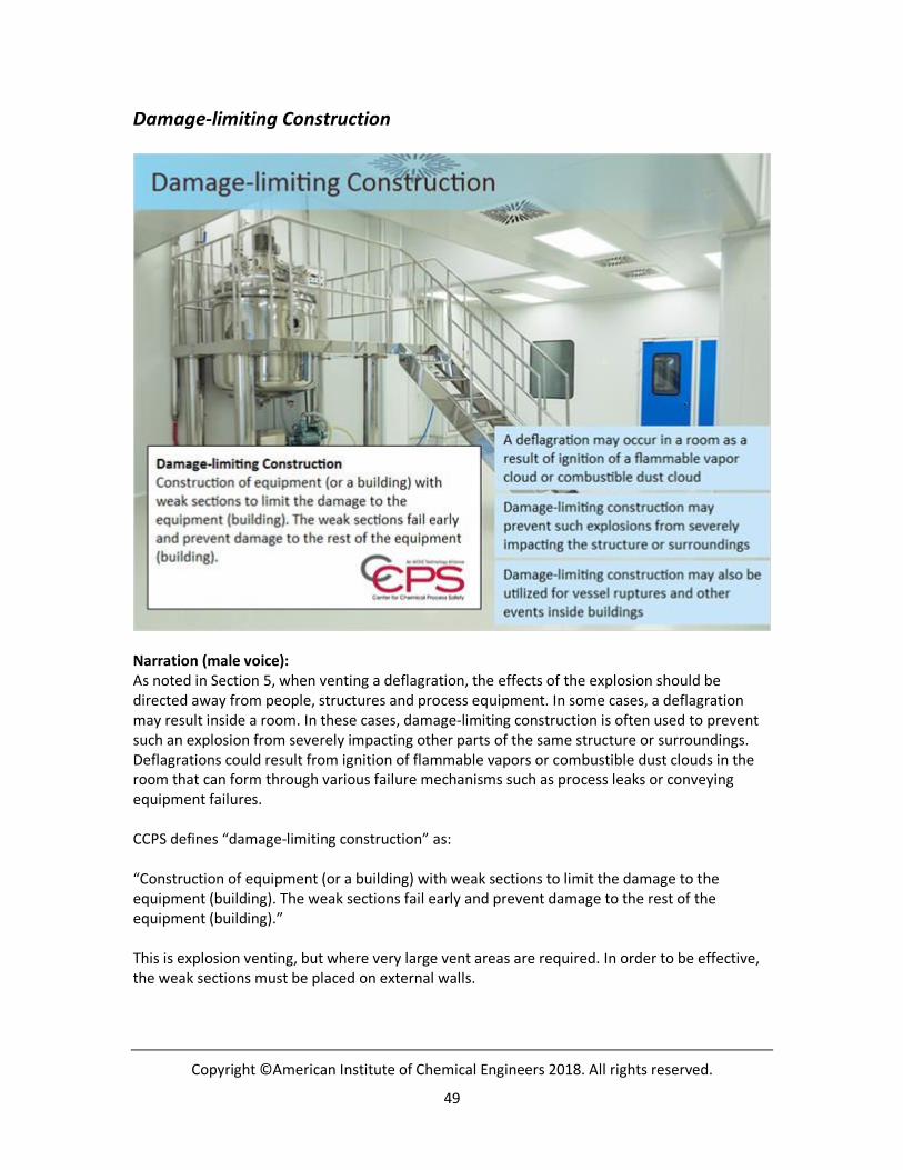
Damage-limiting Construction
Narration (male voice):
As noted in Section 5, when venting a deflagration, the effects of the explosion should be
directed away from people, structures and process equipment. In some cases, a deflagration
may result inside a room. In these cases, damage-limiting construction is often used to prevent
such an explosion from severely impacting other parts of the same structure or surroundings.
Deflagrations could result from ignition of flammable vapors or combustible dust clouds in the
room that can form through various failure mechanisms such as process leaks or conveying
equipment failures.
CCPS defines “damage-limiting construction” as:
“Construction of equipment (or a building) with weak sections to limit the damage to the
equipment (building). The weak sections fail early and prevent damage to the rest of the
equipment (building).”
This is explosion venting, but where very large vent areas are required. In order to be effective,
the weak sections must be placed on external walls.

Copyright ©American Institute of Chemical Engineers 2018. All rights reserved.
50
Other events – such as vessel ruptures inside a building – can also be the basis for damage-
limiting construction.

Copyright ©American Institute of Chemical Engineers 2018. All rights reserved.
51
Directing Explosion Products
Narration (male voice):
When properly designed, a structure – such as a room – can serve to control the forces of an
explosion in such a way that, even though an unwanted event has occurred within the structure,
a significant measure of protection is achieved.
Excluding full containment structures, most structures attempt to direct the forces of the
explosion (blast waves and missiles) away from other process equipment or potentially occupied
areas.

Copyright ©American Institute of Chemical Engineers 2018. All rights reserved.
52
Explosives Manufacturers
Narration (male voice):
As you might expect, manufacturers of explosives are particularly concerned with accidental
explosions due to the nature of the materials they work with. Among other safety measures,
such as damage-limiting construction, these facilities often use minimization (no more than a
specified amount of explosive in one location) and separation distance (minimum distance
between storage locations) to prevent shock ignition of explosive material in neighboring
buildings.

Copyright ©American Institute of Chemical Engineers 2018. All rights reserved.
53
Design Techniques – NFPA 68
Narration (male voice):
NFPA 68 not only provides prescriptive design techniques for damage-limiting construction, but
also includes design standards for deflagration vent sizing of vessels and other equipment
involving dust, flammable vapor, or mixtures of dust and flammable vapor.

Copyright ©American Institute of Chemical Engineers 2018. All rights reserved.
54
Performance-based Design Techniques
Narration (male voice):
Per NFPA 68, design of deflagration vents can also be done using either of these two techniques,
as long as the resulting design meets the performance criteria:
• Testing; and
• Computational Fluid Dynamics (CFD).
Testing is typically costly but can be done if the circumstances are unique. The scale of the test is
important in that combustion events are often influenced by scale.
Computational fluid dynamics (CFD) programming codes are available that are designed
specifically to model vapor cloud explosions (VCEs) and other types of explosions. These models
have been tested and validated for explosions and are in wide use across industry. This type of
modeling involves using a three dimensional representation of the area of interest where
different accidental release and explosion scenarios are modeled and hazards from flame and
blast are quantified; the results are used to improve the facility design.

Copyright ©American Institute of Chemical Engineers 2018. All rights reserved.
55
When using CFD, it’s important to understand which programming code or codes to use for your
application in order to get a meaningful result. Some codes are well developed and validated for
vapor cloud explosions outdoors, but may not handle flammable vapor/air explosions indoors
well enough for design purposes. Other codes may handle condensed phase explosive blast
indoors well, but may not be as well validated for flammable vapor/air explosions.
These methods are used to size and design explosion vents and to evaluate the consequences of
explosions so that people, buildings, and equipment are located such that the operating risk is
tolerable.
[Female voice]
Click the CFD image to watch a brief visualization of a blast wave from a vapor cloud explosion
(VCE).
CFD VCE model (Slide Layer)

Copyright ©American Institute of Chemical Engineers 2018. All rights reserved.
56
SECTION 7: Facility Siting for Explosions
Narration:
[No narration]

Copyright ©American Institute of Chemical Engineers 2018. All rights reserved.
57
Separation Distance
Narration (male voice):
When considering facility siting issues (such as where occupied structures will be located),
separation distance from processes and hazardous materials is one of the most important
factors to keep in mind to protect against the effects of explosions, particularly the blast wave
and missiles and fragments.
Personnel who do not regularly need to go to the manufacturing area should not, as a general
rule, be located near the facility such that they are potentially impacted by fire or explosion
hazards.

Copyright ©American Institute of Chemical Engineers 2018. All rights reserved.
58
Building Hazards to Design Against
Narration (male voice):
Some examples of building hazards to design against include:
• Collapse of walls, and especially roofs – these are major hazards to building occupants;
Window hazards; and
• Objects inside that can be propelled and become hazardous.

Copyright ©American Institute of Chemical Engineers 2018. All rights reserved.
59
Case Study
Narration (male voice):
The runaway reaction and subsequent explosion that occurred at the T2 Laboratories plant in
Jacksonville, Florida in 2007 provides some excellent lessons regarding poor siting of an
occupied structure as well as a structure with no blast protection.
The blast, equivalent to about 635 kilograms of TNT, damaged buildings and injured off-site
office workers over 100 meters away.
While current methods for estimating the consequences of bursting vessels do not use TNT
equivalence, the quantification of the explosion energy in these terms is helpful to convey the
relative severity potential of an explosion.
A video about the case is presented on the next slide.

Copyright ©American Institute of Chemical Engineers 2018. All rights reserved.
60
Case Study – Video
Narration:
[Use video’s CC feature to read transcript of narration embedded in video]

Copyright ©American Institute of Chemical Engineers 2018. All rights reserved.
61
Facility Siting Standards and Guidelines
Narration (female voice):
You can learn more about facility siting best practices from these resources:
• American Petroleum Institute (API) 752: Management of Hazards Associated With
Location of Process Plant Permanent Buildings;
• API 753: Management of Hazards Associated With Location of Process Plant Portable
Buildings;
• API 756: Management of Hazards Associated With Location of Process Plant Tents;
• CCPS Guidelines for Siting and Layout of Facilities; and
• UK Chemical Industries Association, 2010, Guidance for the Location and Design of
Occupied Buildings on Chemical Manufacturing Sites.
You can click the images of the documents to learn about them.

Copyright ©American Institute of Chemical Engineers 2018. All rights reserved.
62
SECTION 8: Standards and Guidelines for Explosion Prevention and
Protection
Narration:
[No narration]

Copyright ©American Institute of Chemical Engineers 2018. All rights reserved.
63
Resources
Narration (male voice):
In this last section, we’ll provide a brief overview of standards and guidelines for explosion
prevention and protection. In the U.S., the National Fire Protection Association provides these
standards:
• NFPA 67: Guide on Explosion Protection for Gaseous Mixtures in Pipe Systems;
• NFPA 68: Standard on Explosion Protection by Deflagration Venting;
• NFPA 69: Standard on Explosion Prevention Systems; and
• NFPA 497: Recommended Practice for the Classification of Flammable Gases, Liquids or
Vapors and of Hazardous (Classified) Locations for Electrical Installations in Chemical
Process Areas.
Examples of European standards include:
• CEN EN 14491: Dust Explosion Venting Protective Systems; and
• CEN EN 1127: Explosive Atmospheres – Explosion Prevention and Protection.

Copyright ©American Institute of Chemical Engineers 2018. All rights reserved.
64
[Female voice]
Click each guideline and standard for a brief description and a link where you can learn more.
NFPA 67 (Slide Layer)
[When NFPA 67 is clicked…]
NFPA 67: Guide on Explosion Protection for Gaseous Mixtures in Pipe Systems provides criteria
for the design, installation, and operation of piping systems that contain or may contain
flammable vapor mixtures to prevent and protect against damage from deflagrations or
detonations due to combustion of flammable atmospheres therein.

Copyright ©American Institute of Chemical Engineers 2018. All rights reserved.
65
NFPA 68 (Slide Layer)
[When NFPA 68 is clicked…]
NFPA 68: Standard on Explosion Protection by Deflagration Venting applies to the design,
location, installation, maintenance, and use of devices and systems that vent the combustion
gases and pressures resulting from a deflagration within an enclosure so that structural and
mechanical damage is minimized.

Copyright ©American Institute of Chemical Engineers 2018. All rights reserved.
66
NFPA 69 (Slide Layer)
[When NFPA 69 is clicked…]
NFPA 69: Standard on Explosion Prevention Systems provides requirements for installing
systems for the prevention and control of explosions in enclosures that contain flammable
concentrations of flammable gases, vapors, mists, dusts, or hybrid mixtures.

Copyright ©American Institute of Chemical Engineers 2018. All rights reserved.
67
NFPA 497 (Slide Layer)
[When NFPA 497 is clicked…]
NFPA 497 Recommended Practice for the Classification of Flammable Gases, Liquids or Vapors
and of Hazardous (Classified) Locations for Electrical Installations in Chemical Process Areas
provides criteria to determine ignitability hazards in chemical process areas using flammable
liquids, gases, or vapors to assist in the selection of electrical systems and equipment for safe
use in Class I hazardous (classified) locations.

Copyright ©American Institute of Chemical Engineers 2018. All rights reserved.
68
CEN EN 14491 (Slide Layer)
[When CEN EN 14491 is clicked…]
CEN EN 14491: Dust Explosion Venting Protective Systems specifies the basic requirements of
design for the selection of a dust explosion venting protective system. The standard is one of a
series including EN 14797: Explosion Venting Devices, and EN 14460: Explosion Resistant
Equipment. The three standards together represent the concept of dust explosion venting.

Copyright ©American Institute of Chemical Engineers 2018. All rights reserved.
69
CEN EN 1127 (Slide Layer)
[When CEN EN 1127 is clicked…]
CEN EN 1127: Explosive Atmospheres – Explosion Prevention and Protection specifies methods
for the identification and assessment of hazardous situations leading to explosion and the
design and construction measures appropriate for the required safety.

Copyright ©American Institute of Chemical Engineers 2018. All rights reserved.
70
Unit 5 Summary
Narration (male voice):
We’ve reached the end of the fifth unit in the Explosion Hazards course. Having completed this
unit, titled “Explosion Prevention and Protection Techniques,” you should now be able to:
• Ask pertinent questions regarding explosion prevention and protection techniques
during the design of projects and periodic safety reviews of process systems;
• Suggest potential methods of explosion prevention and protection based on commonly
used approaches; and
• Locate common standards and guidelines on explosion prevention and protection.
On the next slide, we’ll take a brief look back at the main topics we covered in this course.

Copyright ©American Institute of Chemical Engineers 2018. All rights reserved.
71
Course Summary
Narration (male voice):
We covered many topics in this Explosion Hazards course.
In Unit 1, titled “Explosion Hazards Case Studies”…
• You learned the definition of the term “explosion;” and
• You explored some examples of major industrial explosion incidents and their influence
on some of the key regulations covering the process safety community.
In Unit 2, titled “Explosion Types”…
• You learned how to categorize a potential explosion scenario by the type of explosion;
and
• You learned how to identify the source of the explosion energy, given a potential
explosion scenario.
In Unit 3, titled “Characterization of Explosion Hazards,” we defined and described potential
hazards associated with explosions.

Copyright ©American Institute of Chemical Engineers 2018. All rights reserved.
72
In Unit 4, titled “Tests to Characterize Explosion Hazards,” you learned how to assess the
relative explosion hazard of a material or mixture based on the physical characteristics.
And as we just summarized on the previous slide, this final unit presented ways in which
explosion hazards can be prevented and protected against.
Before closing the course, please take the Unit 5 quiz. The quiz introduction is on the next slide.