Embed Size (px)
Citation preview

Moeller Wiring Manual 02/05
Specifications, Formulae, Tables
9
Page
Marking of electrical equipment 9-2
Circuit symbols, European – North America 9-14
Circuit diagram example to North American specifications 9-27
Approval authorities worldwide 9-28
Test authorities and approval stamps 9-32
Protective measures 9-34
Overcurrent protection of cables and conductors 9-43
Electrical equipment of machines 9-51
Measures for risk reduction 9-56
Measures for risk avoidance 9-57
Degrees of protection for electrical equipment 9-58
North American classifications for control switches 9-68
Utilisation categories for contactors 9-70
Utilisation categories for switch-disconnectors 9-74
Rated motor currents 9-77
Conductors 9-81
Formulae 9-90
International unit system 9-94
9-1

Moeller Wiring Manual 02/05
9
Specifications, Formulae, TablesMarking of electrical equipment
General
Extracts from the DIN Standards with VDE Classification are quoted with the permission of the DIN (Deutsches Institut für Normung e.V.) and the VDE (Verband der Elektrotechnik Elektronik Informationstechnik e.V.) It is imperative for the use of the standards that the issue with the latest date is used. These are available from VDE-VERLAG GMBH, Bismarckstr. 33, 10625 Berlin and Beuth Verlag GmbH, Burggrafenstr. 6, 10787 Berlin.
Marking to DIN EN 61346-2:2000-12 (IEC 61346-2:2000)
Moeller has decided, with a transitional period, to use the above mentioned standards. Deviation from the, up to now, normal marking determines now in the first place the function of the electrical equipment in the respective circuit of the code letter. The outcome is that there is a lot of freedom in the selection of the code letters. Example for a resistance • Normal current limiter: R• Heater resistor: E• Measurement resistor: B
As well as that, Moeller specific decisions have been made with regard to the interpretation of the standard that sometimes deviate from the standard. • The marking of connection terminals are not
readable from the right. • A second code letter for the marking of the use
of the equipment is not given,e. g.: timer relay K1T becomes K1.
• Circuit-breakers with the main function of protection are still marked with Q. They are numbered from 1 to 10 from the top left.
• Contactors are newly marked with Q and numbered from 11 to nn. e. g.: K91M becomes Q21.
• Relays remain K and are numbered from 1 to n.
The marking appears in a suitable position as close as possible to the circuit symbol. The marking forms the link between the equipment in the installations and the various circuit documents (wiring diagrams, parts lists, circuit diagrams, instructions). For simpler maintenance, the complete marking or part of it, can be affixed on or near to the equipment.
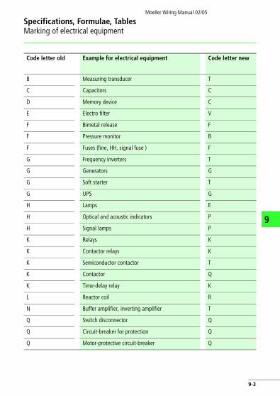
Selected equipment with a comparison of the Moeller used code letters old – new a Table, Page 9-3.
9-2
Specifications, Formulae, TablesMarking of electrical equipment
Moeller Wiring Manual 02/05
9
Code letter old Example for electrical equipment Code letter new
B Measuring transducer T
C Capacitors C
D Memory device C
E Electro filter V
F Bimetal release F
F Pressure monitor B
F Fuses (fine, HH, signal fuse ) F
G Frequency inverters T
G Generators G
G Soft starter T
G UPS G
H Lamps E
H Optical and acoustic indicators P
H Signal lamps P
K Relays K
K Contactor relays K
K Semiconductor contactor T
K Contactor Q
K Time-delay relay K
L Reactor coil R
N Buffer amplifier, inverting amplifier T
Q Switch disconnector Q
Q Circuit-breaker for protection Q
Q Motor-protective circuit-breaker Q
9-3

Specifications, Formulae, TablesMarking of electrical equipment
Moeller Wiring Manual 02/05
9
Q Star-delta switches Q
Q Disconnect switch Q
R Variable resistor R
R Measurement resistor B
R Heating resistor E
S Control circuit devices S
S Push-button S
S Position switch B
T Potential transformer T
T Current transformer T
T Transformers T
U Frequency converter T
V Diodes R
V Rectifier T
V Transistors K
Z EMC filter K
Z Suppressors and arc quenching devices F
Code letter old Example for electrical equipment Code letter new
9-4

Specifications, Formulae, TablesMarking of electrical equipment
Moeller Wiring Manual 02/05
9
Component marking in the USA and Canada to NEMA ICS 1-2001, ICS 1.1-1984, ICS 1.3-1986
In order to differentiate between devices with similar functions, 3 figures and/or letters can be added to the marking. When using two or more of these markings, the function marking is usually put first.
Example:The relay which introduces the first jog function is marked with “1 JCR”. That means here:1 = numerical specificationJ = jog function of the equipmentCR = control relay (contactor relay) – type of equipment
9-5
Specifications, Formulae, TablesMarking of electrical equipment
Moeller Wiring Manual 02/05
9
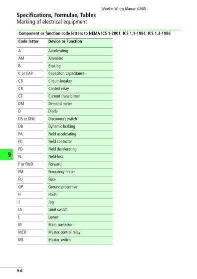
Component or function code letters to NEMA ICS 1-2001, ICS 1.1-1984, ICS 1.3-1986
Code letter Device or Function
A Accelerating
AM Ammeter
B Braking
C or CAP Capacitor, capacitance
CB Circuit-breaker
CR Control relay
CT Current transformer
DM Demand meter
D Diode
DS or DISC Disconnect switch
DB Dynamic braking
FA Field accelerating
FC Field contactor
FD Field decelerating
FL Field-loss
F or FWD Forward
FM Frequency meter
FU Fuse
GP Ground protective
H Hoist
J Jog
LS Limit switch
L Lower
M Main contactor
MCR Master control relay
MS Master switch
9-6

Specifications, Formulae, TablesMarking of electrical equipment
Moeller Wiring Manual 02/05
9
OC Overcurrent
OL Overload
P Plugging, potentiometer
PFM Power factor meter
PB Pushbutton
PS Pressure switch
REC Rectifier
R or RES Resistor, resistance
REV Reverse
RH Rheostat
SS Selector switch
SCR Silicon controlled rectifier
SV Solenoid valve
SC Squirrel cage
S Starting contactor
SU Suppressor
TACH Tachometer generator
TB Terminal block, board
TR Time-delay relay
Q Transistor
UV Undervoltage
VM Voltmeter
WHM Watthour meter
WM Wattmeter
X Reactor, reactance
Code letter Device or Function
9-7
Specifications, Formulae, TablesMarking of electrical equipment
Moeller Wiring Manual 02/05
9
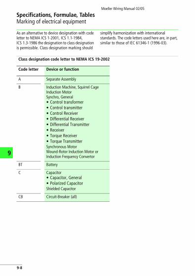
As an alternative to device designation with code letter to NEMA ICS 1-2001, ICS 1.1-1984, ICS 1.3-1986 the designation to class designation is permissible. Class designation marking should
simplify harmonization with international standards. The code letters used here are, in part, similar to those of IEC 61346-1 (1996-03).
Class designation code letter to NEMA ICS 19-2002
Code letter Device or function
A Separate Assembly
B Induction Machine, Squirrel CageInduction MotorSynchro, General• Control transformer• Control transmitter• Control Receiver• Differential Receiver• Differential Transmitter• Receiver• Torque Receiver• Torque TransmitterSynchronous MotorWound-Rotor Induction Motor or Induction Frequency Convertor
BT Battery
C Capacitor• Capacitor, General• Polarized CapacitorShielded Capacitor
CB Circuit-Breaker (all)
9-8

Specifications, Formulae, TablesMarking of electrical equipment
Moeller Wiring Manual 02/05
9
D, CR Diode• Bidirectional Breakdown Diode• Full Wave Bridge Rectifier• Metallic Rectifier• Semiconductor Photosensitive• Cell• Semiconductor Rectifier• Tunnel Diode• Unidirectional Breakdown Diode
D, VR Zener Diode
DS AnnunciatorLight Emitting DiodeLamp• Fluorescent Lamp• Incandescent Lamp• Indicating Lamp
E Armature (Commutor and Brushes)
Lightning ArresterContact• Electrical Contact• Fixed Contact• Momentary ContactCore• Magnetic CoreHorn GapPermanent MagnetTerminalNot Connected Conductor
Code letter Device or function
9-9

Specifications, Formulae, TablesMarking of electrical equipment
Moeller Wiring Manual 02/05
9
F Fuse
G Rotary Amplifier (all)A.C. GeneratorInduction Machine, Squirrel CageInduction Generator
HR Thermal Element Actuating Device
J Female Disconnecting DeviceFemale Receptacle
K Contactor, Relay
L Coil• Blowout Coil• Brake Coil• Operating CoilField• Commutating Field• Compensating Field• Generator or Motor Field• Separately Excited Field• Series Field• Shunt FieldInductorSaturable Core ReactorWinding, General
LS Audible Signal Device• Bell• Buzzer• Horn
M Meter, Instrument
Code letter Device or function
9-10

Specifications, Formulae, TablesMarking of electrical equipment
Moeller Wiring Manual 02/05
9
P • Male Disconnecting Device• Male Receptable
Q Thyristor• NPN Transistor• PNP Transistor
R Resistor• Adjustable Resistor• Heating Resistor• Tapped Resistor• RheostatShunt• Instrumental Shunt• Relay Shunt
S Contact• Time Closing Contact• Time Opening Contact• Time Sequence Contact• Transfer Contact• Basic Contact Assembly• Flasher
Code letter Device or function
9-11
Specifications, Formulae, TablesMarking of electrical equipment
Moeller Wiring Manual 02/05
9
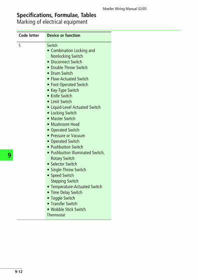
S Switch• Combination Locking and
Nonlocking Switch• Disconnect Switch• Double Throw Switch• Drum Switch• Flow-Actuated Switch• Foot Operated Switch• Key-Type Switch• Knife Switch• Limit Switch• Liquid-Level Actuated Switch• Locking Switch• Master Switch• Mushroom Head• Operated Switch• Pressure or Vacuum• Operated Switch• Pushbutton Switch• Pushbutton Illuminated Switch,
Rotary Switch• Selector Switch• Single-Throw Switch• Speed Switch
Stepping Switch• Temperature-Actuated Switch• Time Delay Switch• Toggle Switch• Transfer Switch• Wobble Stick SwitchThermostat
Code letter Device or function
9-12

Specifications, Formulae, TablesMarking of electrical equipment
Moeller Wiring Manual 02/05
9
T Transformer• Current Transformer• Transformer, General• Polyphase Transformer• Potential Transformer
TB Terminal Board
TC Thermocouple
U Inseparable Assembly
V Pentode, Equipotential Cathode Phototube, Single Unit, Vacuum Type Triode Tube, Mercury Pool
W Conductor• Associated• Multiconductor• ShieldedConductor, General
X Tube Socket
Code letter Device or function
9-13

Moeller Wiring Manual 02/05
9
Specifications, Formulae, TablesCircuit symbols, European – North America
Circuit symbols to DIN EN, NEMA ICS
The following comparison of circuit symbols is based upon the following international/national specifications:• DIN EN 60617-2 to DIN EN 60617-12• NEMA ICS 19-2002
Description DIN EN NEMA ICS
Conductors, connectors
Junction of conductors
or or
Connection of conductors (node)
Terminal
Terminal strip/block
Conductor
03-02-04 03-02-05
03-02-01
03-02-02
03-02-03
1 2 3 4 1 2 3 4
03-01-01
9-14

Specifications, Formulae, TablesCircuit symbols, European – North America
Moeller Wiring Manual 02/05
9
Conductor (for later expansion)
Line of application, general symbol
Line of application, optional, denoting small interval
Separation between two fields
Line of separation between functional units
Screen
Earth, general symbol Ground, general symbol
Protective earth Protective ground
Connector with plug and socket
or
Isolating point, lug, closed
Description DIN EN NEMA ICS
103-01-01
02-12-01
02-12-04
02-01-06
02-01-06
02-01-07
02-15-01GRD
02-15-03
03-03-05 03-03-06
03-03-18
9-15

Specifications, Formulae, TablesCircuit symbols, European – North America
Moeller Wiring Manual 02/05
9
Passive components
Resistor, general symbol or or
Resistor with fixed tappings or
Variable resistor, general symbol
Adjustable resistor
Resistor with sliding contact, potentiometer
Winding, inductance, general symbol
or
Winding with fixed tapping
Capacitor, general symbol or or
Variable capacitor
Description DIN EN NEMA ICS
04-01-02 04-01-02
RES
04-01-09
04-01-03
RES
04-01-07
04-03-01 04-03-02
04-03-06
04-02-01 04-02-02
104-02-01
9-16

Specifications, Formulae, TablesCircuit symbols, European – North America
Moeller Wiring Manual 02/05
9
Signalling units
Visual indicator, general symbol
*with colour stated
Indicator light, general symbol or or
*with colour stated
Buzzer or
Horn, claxon
Operating devices
Manual operation, general use
Operated by pushing
Operated by pulling
Operated by turning
Operated by key
Operated by rollers, sensors
Description DIN EN NEMA ICS
08-10-01
08-10-1108-10-10
ABU
08-10-05
HN
02-13-01
02-13-05
02-13-03
02-13-04
02-13-13
02-13-15
9-17

Specifications, Formulae, TablesCircuit symbols, European – North America
Moeller Wiring Manual 02/05
9
Stored energy mechanism, general symbol
Switch mechanism with mechanical release
Operated by motor
Emergency switch
Operated by electromagnetic overcurrent protection
Operated by thermal overcurrent protection
Electromagnetic operation
Control by fluid level
Electromechanical, electromagnetic operating devices
Electromechanical operating device, general symbol, relay coil, general symbol
or or
x device code letter
Operating device with special features, general symbol
Description DIN EN NEMA ICS
02-13-20
102-05-04
M
02-13-26
MOT
02-13-08
02-13-24
02-13-25
OL
02-13-23
02-14-01
07-15-01
9-18

Specifications, Formulae, TablesCircuit symbols, European – North America
Moeller Wiring Manual 02/05
9
Electromechanical operating device with On-delay
Electromechanical device with Off-delay
Electromechanical device with On- and Off-delay
Electromechanical device of a thermal relay
Contacts
Make contact or or
Break contact or
Changeover contact with interruption
or
Early-make contact of a contact assembly
Late-break contact of a contact assembly
Make contact, delayed when closing or
Break contact, delayed when reclosing
or
Description DIN EN NEMA ICS
07-15-08
SO
07-15-07
SR
07-15-09
SA
07-15-21
07-02-01 07-02-02
07-02-03
07-02-04
07-04-01
TC, TDC, EM
07-04-03
TO, TDO, LB
07-05-02 07-05-01T.C.
07-05-03 07-05-04T.O.
9-19

Specifications, Formulae, TablesCircuit symbols, European – North America
Moeller Wiring Manual 02/05
9
Control devices
Push-button (not stay-put)
Spring-return switch with break contact, manually operated by pushing, e.g. push-button
Spring-return switch with make and break contacts, manually operated by pushing
Spring-return switch with latching position and one make contact, manually operated by pushing
Spring-return switch with latching position and one break contact, manually operated by striking (e.g. mushroom button)
Position switch (make contact) Limit switch (make contact)
Position switch (break contact)Limit switch (break contact)
Spring-return switch with make contact, mechanically operated, make contact closed
Description DIN EN NEMA ICS
07-07-02
PB
PB
PB
PB
07-08-01
LS
07-08-02
LS
LS
9-20

Specifications, Formulae, TablesCircuit symbols, European – North America
Moeller Wiring Manual 02/05
9
Spring-return switch with break contact, mechanically operated, break contact open
Proximity switch (break contact), actuated by the proximity of iron
Proximity switch, inductive, make contact
Proximity switch, block diagram
Under-pressure relay, make contact or
Pressure switch, break contact or
Float switch, make contact
Float switch, break contact
Description DIN EN NEMA ICS
LS
Fe
07-20-04
Fe
07-19-02
07-17-03
P< P
P > P
9-21

Specifications, Formulae, TablesCircuit symbols, European – North America
Moeller Wiring Manual 02/05
9
Switchgear
Contactor (make contact)
x code letter
3 pole contactor with bimetal relay (3 thermal elements)
x code letter
3 pole switch-disconnector
3 pole circuit-breaker
3 pole breaker with switch mechanism with three thermoelectric overcurrent releases, three electromagnetic overcurrent releases, motor-protective circuit-breaker
Fuse, general symbol or or
Transformers, current transformers
Transformers with two windings or or
Description DIN EN NEMA ICS
07-13-02
OL
07-13-06
DISC
07-13-05
CB
107-05-01
l > l > l >
x x x
07-21-01
FU
06-09-02 06-09-01
9-22

Specifications, Formulae, TablesCircuit symbols, European – North America
Moeller Wiring Manual 02/05
9
Autotransformer or or
Current transformer or
Machines
Generator or
Motor, general symbol or
DC motor, general symbol
AC motor, general symbol
Three-phase asynchronous motor with squirrel-cage rotor
Three-phase asynchronous motor with slip-ring rotor
Description DIN EN NEMA ICS
06-09-07
06-09-06
06-09-11 06-09-10
G
06-04-01
G GEN
M
06-04-01
M MOT
M
06-04-01
M
06-04-01
M~
M3~
06-08-01
M3~
06-08-03
9-23

Specifications, Formulae, TablesCircuit symbols, European – North America
Moeller Wiring Manual 02/05
9
Semiconductor components
Static input
Static output
Static input with negation
Static output with negation
Dynamic input, change of status from 0 to 1 (L/H)
Dynamic input with negation, change of status from 1 to 0 (H/L)
AND gate, general symbol
OR gate, general symbol
NOT gate, inverter
AND with negated output, NAND
Description DIN EN NEMA ICS
12-07-01
12-07-02
12-07-07
12-07-08
&
12-27-02
A
� 1
12-27-01
OR
1
12-27-11
OR
&12
1312-28-01
A
9-24

Specifications, Formulae, TablesCircuit symbols, European – North America
Moeller Wiring Manual 02/05
9
OR with negated output, NOR
Exclusive OR gate, general symbol
RS flip-flop
Monostable gate, cannot be triggered during the output pulse, general symbol
Delay, variable with indication of delay values
Semiconductor diode, general symbol
Limiting diode Zener diode
Light-emitting diode (LED), general symbol
Bi-directional diode, diac
Thyristor, general symbol
Description DIN EN NEMA ICS
� 134512-28-02
OR
= 1
12-27-09
OE
SR
12-42-01
S FF 1TC 0
1
12-44-02
SS
02-08-05
TPAdj.m/ms
05-03-01
(A) (K)
05-03-06
05-03-02
05-03-09
(T) (T)
05-04-04
(A) (K)
9-25

Specifications, Formulae, TablesCircuit symbols, European – North America
Moeller Wiring Manual 02/05
9
PNP transistor or
NPN transistor, in which the collector is connected to the enclosure
or
Description DIN EN NEMA ICS
05-05-01
(A) (K) (E) (C)
(B)
05-05-02
(A)(K) (E) (C)
(B)
9-26

Moeller Wiring Manual 02/05
Specifications, Formulae, TablesCircuit diagram example to North American specifications
9
Direct-on-Line Motor-Starters
Fuseless with circuit-breakers
L1
L2
L3
CB L1L2
L3
T1T2
T3
460 V
H3H1 H2 H4
X1 X2115 VFU
M
MTR
X1 X2
A1 A2W
2 PB
M1313
1414
M
1211
1 PBSTOP START
9-27

Moeller Wiring Manual 02/05
9
Specifications, Formulae, TablesApproval authorities worldwide
Abbrevi-ation
Full title Country
ABS American Bureau of Shipping USA
AEI Associazione Elettrotechnica ed Elettronica ItalianaItalian electrotechnical industry organisation
Italy
AENOR Asociacion Española de Normalización y CertificaciónSpanish organisation for standards and certification
Spain
ALPHA Gesellschaft zur Prüfung und Zertifizierungvon NiederspannungsgerätenGerman test laboratories association
Germany
ANSI American National Standards Institute USA
AS Australian Standard Australia
ASA American Standards Association USA
ASTA Association of Short-Circuit Testing Authorities Great Britain
BS British Standard Great Britain
BV Bureau VeritasShip´s classification association
France
CEBEC Comité Electrotechnique BelgeBelgian electrotechnical product quality mark
Belgium
CEC Canadian Electrical Code Canada
CEI Comitato Elettrotecnico ItalianoItalian standards organisation
Italy
CEI Commission Electrotechnique InternationaleInternational electrotechnical commission
Switzerland
CEMA Canadian Electrical Manufacturer’s Association Canada
CEN Comité Européen de NormalisationEuropean standards committee
Europe
CENELEC Comité Européen de Normalisation ÉlectrotechniqueEuropean committee for electrotechnical standards
Europe
9-28

Specifications, Formulae, TablesApproval authorities worldwide
Moeller Wiring Manual 02/05
9
CSA Canadian Standards Association Canada
DEMKO Danmarks Elektriske MaterielkontrolDanish material control for electrotechnical products
Denmark
DIN Deutsches Institut für NormungGerman institute for standardisation
Germany
DNA Deutscher Normenausschuss German standards committee
Germany
DNV Det Norsk VeritasShip classification association
Norway
EN European standard Europe
ECQAC Electronic Components Quality Assurance Committee Europe
ELOT Hellenic Organization for StandardizationGreek organization for standardization
Greece
EOTC European Organization for Testing and Certification Europe
ETCI Electrotechnical Council of Ireland Ireland
GL Germanischer LloydShip classification association
Germany
HD Harmonization document Europe
IEC International Electrotechnical Commission –
IEEE Institute of Electrical and Electronics Engineers USA
IPQ Instituto Portoguês da QualidadePortuguese quality institute
Portugal
ISO International Organization for Standardization –
Abbrevi-ation
Full title Country
9-29

Specifications, Formulae, TablesApproval authorities worldwide
Moeller Wiring Manual 02/05
9
JEM Japanese Electrical Manufacturers AssociationElectrical industry association
Japan
JIC Joint Industry Conference USA
JIS Japanese Industrial Standard Japan
KEMA Keuring van Elektrotechnische Materialen Testing institute for electrotechnical products
Netherlands
LOVAG Low Voltage Agreement Group –
LRS Lloyd's Register of Shipping Great Britain
MITI Ministry of International Trade and Industry Japan
NBN Norme BelgeBelgian standard
Belgium
NEC National Electrical Code USA
NEMA National Electrical Manufacturers Association USA
NEMKO Norges Elektriske Materiellkontroll Norwegian testing institute for electrotechnical products
Norway
NEN Nederlandse NormDutch standard
Netherlands
NFPA National Fire Protection Association USA
NKK Nippon Kaiji Kyakai Japanese classification association
Japan
OSHA Occupational Safety and Health Administration USA
ÖVE Österreichischer Verband für ElektrotechnikAustrian electrotechnical association
Austria
PEHLA Prüfstelle elektrischer HochleistungsapparateElectrical high-performance apparatus test laboratory of the association for electrical high-performance testing
Germany
Abbrevi-ation
Full title Country
9-30

Specifications, Formulae, TablesApproval authorities worldwide
Moeller Wiring Manual 02/05
9
PRS Polski Rejestr Statków Ship classification association
Poland
PTB Physikalisch-Technische BundesanstaltGerman physical/technical federal agency
Germany
RINA Registro Italiano Navale Italian ship classification association
Italy
SAA Standards Association of Australia Australia
SABS South African Bureau of Standards South Africa
SEE Service de l'Energie de l'Etat Luxemburg authority for standardisation, testing and certi-fication
Luxemburg
SEMKO Svenska Elektriska Materielkontrollanstalten Swedish test institute for electrotechnical products
Sweden
SEV Schweizerischer Elektrotechnischer VereinSwiss electrotechnical association
Switzerland
SFS Suomen Standardisoimisliito r.y.Finnish standardisation association, Finnish standard
Finland
STRI The Icelandic Council for Standardization Iceland
SUVA Schweizerische Unfallversicherungs-AnstaltSwiss accident insurance federal agency
Switzerland
TÜV Technischer ÜberwachungsvereinTechnical inspection association
Germany
UL Underwriters' Laboratories Inc. USA
UTE Union Technique de l'Electricité Electrotechnical federation
France
VDE Verband der Elektrotechnik, Elektronik, Informationstechnik (Verband Deutscher Elektrotechniker)Association of electrical, electronics and information tech-nology
Germany
ZVEI Zentralverband Elektrotechnik- und ElektronikindustrieCentral association of the electrical and electronic industry
Germany
Abbrevi-ation
Full title Country
9-31

Moeller Wiring Manual 02/05
9
Specifications, Formulae, TablesTest authorities and approval stamps
Test authorities and approval stamps in Europe and North America
Moeller devices have in their basic design all worldwide necessary approvals including those for the USA. Some devices, such as circuit-breakers, are in their basic design usable worldwide with the exception of USA and Canada. For export to North America devices are available with a special UL and CSA approval. In all cases special country specific installation and operating specifications, installation ,materials and types must be taken into account as well as special circumstances such as difficult climatic conditions. Since January 1997 all devices that conform to the European low-voltage guidelines and are for sale
in the European Union must be marked with the CE mark. The CE mark shows that the marked device corresponds with all relevant requirements and standards. This marking duty allows unlimited use of this device within the European economic area. Approval and marking for their own country is no longer necessary when a device is marked with the CE mark that corresponds to the harmonised standards. (a Table, Page 9-32).An exception is the instalation material. The device group of circuit-breakers and earth-fault protection switches are in certain areas still to be labelled and are therefore marked with the relevant label.
Country Test authority Stamp included in CE mark
Belgium Comité Electrotechnique BelgeBelgisch Elektrotechnisch Comité (CEBEC)
yes, except installation material
Denmark Danmarks Elektriske Materielkontrol (DEMKO)
Yes
Germany Verband Deutscher Elektrotechniker (VDE)
yes, except installation material
Finland FIMKO Yes
France Union Technique de l’Electricité (UTE) yes, except installation material
v
9-32

Specifications, Formulae, TablesTest authorities and approval stamps
Moeller Wiring Manual 02/05
9
Canada Canadian Standards Association (CSA) no, extra or seperate the UL an CSA approval mark
Netherlands Naamloze Vennootschap tot Keuring van Electrotechnische Materialen (KEMA)
Yes
Norway Norges Elektriske Materiellkontrol (NEMKO)
Yes
Russia Goststandart(GOST-)R No
Sweden Svenska Elektriska Materiel-kontrollanstalten (SEMKO)
Yes
Switzerland Schweizerischer Elektrotechnischer Verein (SEV)
yes, except installation material
Czech Republic
– – no, manufacture declaration is enough
Hungary – – no, manufacture declaration is enough
USA Underwriters LaboratoriesListing Recognition
no, extra or seperate the UL an CSA approval mark
Country Test authority Stamp included in CE mark
9-33

Moeller Wiring Manual 02/05
9
Specifications, Formulae, TablesProtective measures
Protection against electrical shock to IEC 364-4-41
A distinction is drawn here between protection against direct contact, protection against indirect contact and protection against both direct and indirect contact.• Protection against direct contact
These are all the measures for the protection of personnel and working animals from dangers
which may arise from contact with live parts of electrical equipment.
• Protection against indirect contactThis is the protection of personnel and working animals from dangers which may arise from accidental contact with components or extraneous conductive parts.
Protection must be ensured by either a) the equipment itself or b) the use of protective measures when erecting the installation or c) a combination of a) and b).
Protective measures
Protection against direct as well as indirect contact
Protection against direct contact
Protection against indirect contact
Protection by extra-low voltage:
– SELV– PELV
Protection by insulation of active parts
Protection by automatic disconnection of the power supply
Protection by covering or encapsulating
Protective insulation (Total insulation) k
Protection by partitioning Protection by non-conductive spaces
Protection by distancing Protection by non-earthed local equipotential bonding
Protective isolation
9-34

Specifications, Formulae, TablesProtective measures
Moeller Wiring Manual 02/05
9
Protection against indirect contact by means of disconnection or indication
The conditions for disconnection are determined by the type of system in use and the protective device selected.
Systems to IEC 364-3/VDE 0100 Part 310
a System earthb Chassisc Impedance
Earth continuity type systems Meaning of designation
TN systemT: direct earthing of a point (system earth) N: chassis directly connected to the system earth
TT systemT: direct earthing of a point (system earth)T: chassis directly earthed, independent of the
earthing of the power supply (system earth)
IT systemI: All live parts isolated from earth or one point
connected to earth via an impedance. T: chassis directly earthed, independent of the
earthing of the power supply (system earth)
L2
N
L1
L3
PE
b
a
L2
N
L1
L3
PE
b
a
L2L1
L3
c b
PE
9-35

Specifications, Formulae, TablesProtective measures
Moeller Wiring Manual 02/05
9
Protective devices and conditions for disconnection to IEC 364-4-1/VDE 0100 Part 410
Type of distribution system
TN system
Protection with System circuit Description so far
Condition for disconnection
Overcurrent protective device
TN-S system separated neutral and earth conductors throughout the system
Zs X Ia F U0 Zs = Impedance of the fault circuit Ia = current, which causes disconnection in:• F 5 s• F 0.2 sin circuits up to 35 A with sockets and hand-held components which can be movedU0 = rated voltage against earthed conductor
FusesMiniature circuit-breakersCircuit-breakers
TN-C systemNeutral conductor and protection functions are combined throughout the system in a single PEN conductor.
Protective multiple earthing
L2
N
L1
L3
PE
L2
PEN
L1
L3
9-36

Specifications, Formulae, TablesProtective measures
Moeller Wiring Manual 02/05
9
Protective devices and conditions for disconnection to IEC 364-4-1/VDE 0100 Part 410
*a Table, Page 9-41
Type of distribution system
TN system
Protection with System circuit Description so far
Condition for disconnection
Overcurrent protective device
TN-C-S systemNeutral conductor and protection functions are in a part of the system combined in a single PEN conductor
Residual-current protective device
Residual-current protective circuit
Zs X IDn F U0 IDn = rated fault current U0 = maximum permissible touch voltage*:(F 50 V AC, F 120 V DC)
Residual voltage protection device (in special case)
Insulation monitoring devices
L2L1
L3NPE(N)
L2L1
L3NPE(N)
9-37

Specifications, Formulae, TablesProtective measures
Moeller Wiring Manual 02/05
9
Protective devices and conditions for disconnection to IEC 364-4-1/VDE 0100 Part 410
*a Table, Page 9-41
Type of distribution system
TT system
Protection with System circuit Description so far
Conditions for indica-tion/disconnection
Overcurrent protective device
FusesMiniature circuit-breakersCircuit-breakers
Protective earth
RA X Ia F UL RA = Earthing resistance of conductive parts of the chassisIa = Current which causes automatic disconnection in F 5 sUL = Maximum per-missible touch volt-age*:(F 50 V AC, F 120 V DC)
Residual-current protective device
Residual-current protective circuit
RA X IΔn F UL IΔn = rated fault current
Residual-voltage protective device (for special cases)
Residual-voltage protective circuit
RA: max. 200 O
L2
PE
L1
L3NPE
PE
L2
PE
L1
L3N
L2L1
L3N
PE PE
F1 F1 F1
L2
N
L1
L3
PE
FU
9-38

Specifications, Formulae, TablesProtective measures
Moeller Wiring Manual 02/05
9
Protective devices and conditions for disconnection to IEC 364-4-1/VDE 0100 Part 410
*a Table, Page 9-41
Type of distribution system
TT system
Protection with System circuit Description up to now
Conditions for indica-tion/disconnection
Insulation monitoring device
–
Overcurrent protection device
Feed back to protective multiple earthing
RA X Id F UL (1)ZS X Ia F Uo (2)RA = Earthing resistance of all conductive parts connected to an earthId = Fault current in the event of the first fault with a negligible impedance between a phase conductor and the protective conductor or element connected to itUL = Maximum permissible touch voltage*:F 50 V AC, F 120 V DC
L2
PE
L1
L3
9-39

Specifications, Formulae, TablesProtective measures
Moeller Wiring Manual 02/05
9
Protective devices and conditions for disconnection to IEC 364-4-1/VDE 0100 Part 410
*a Table, Page 9-41
Type of distribution system
IT system
Protection with System circuit Description so far
Conditions for indica-tion/disconnection
Residual-current protective device
Residual-current protective circuit
RA X IΔn F ULIΔn = rated fault current
Residual voltage protective device (for special cases)
Residual-voltage protective circuit
RA: max. 200 O
Insulation monitoring device
a additional potential equalisation
Protective-conductor system
R X Ia F ULR = Resistance between components and extraneous conductive parts which can be touched simultaneously
L2
PE
L1
L3
PE
F1 F1
L2L1
L3
FU
PE
FU
PE
L2
PE
L1
L3
Z<
�
9-40

Specifications, Formulae, TablesProtective measures
Moeller Wiring Manual 02/05
9
The protective device must automatically disconnect the faulty part of the installation. At no part of the installation may there be a touch voltage or an effective duration greater than that
specified in the table below. The internationally agreed limit voltage with a maximum disconnect time of 5 s is 50 V AC or 120 V DC.
Maximum permissible effective duration dependent on touch voltage to IEC 364-4-41
5.0
2.0
1.0
0.5
0.2
0.1
0.05
0.0250 100 200 300 400
U [V]
t [s]Anticipated touch voltage Max.
permissible disconnection time
AC rms[V]
DC rms[V] [s]
< 50 < 120 ·50 120 5.0
75 140 1.0
90 160 0.5
110 175 0.2
150 200 0.1
220 250 0.05
280 310 0.03
9-41

NotesMoeller Wiring Manual 02/05
9
9-42

Moeller Wiring Manual 02/05
Specifications, Formulae, TablesOvercurrent protection of cables and conductors
9
Cables and conductors must be protected by means of overcurrent protective devices against
excessive warming, which may result both from operational overloading and from short-circuit.
Overload protection
Overload protection means providing protective devices which will interrupt overload currents in the conductors of a circuit before they can cause temperature rises which may damage the conductor insulation, the terminals and connections or the area around the conductors.For the protection of conductors against overload the following conditions must be fulfilled (source: DIN VDE 0100-430)
IB anticipated operating current of the circuit IZ current-carrying capacity of the cable or con-
ductor In rated current of protection device
Note: For adjustable protective devices, In corresponds to the value set. I2 The current which causes tripping of the
protective device under the conditions specified in the equipment regulations (high test current).
Arrangement of protection devices for overload protection Protection devices for overload protection must be fitted at the start of every circuit and at every point where the current-carrying capacity is reduced unless an upstream protection device can ensure protection.
IB F In F IZ
I2 F 1,45 IZ
IA
1.45 � Iz
Characteristics ofprotective device
Operational current
Rated-
or set
ting
curre
nt I n
Tripp
ing cu
rrent
I z
Current-carrying
capacity Iz
Reference values
of conductor IB
9-43

Specifications, Formulae, TablesOvercurrent protection of cables and conductors
Moeller Wiring Manual 02/05
9
Note: Reasons for the current-carrying capacity being reduced:Reduction of the conductor cross-section, a different installation method, different conductor insulation, a different number of conductors.Protective devices for overload protection must not be fitted if interruption of the circuit could
prove hazardous. The circuits must be laid out in such a way that no possibility of overload currents occurring need be considered.Examples:• Energizing circuits for rotating machines• Feeder circuits of solenoids• Secondary circuits of current transformers• Circuits for safety purposes
Short-circuit protection
Short-circuit protection means providing protective devices which will interrupt short-circuit currents in the conductors of a circuit before they can cause a temperature rise which may damage the conductor insulation, the terminals and connections, or the area around the cables and conductors.In general, the permissible disconnection time t for short circuits of up to 5 s duration can be specified approximately using the following equation:
or
The meaning of the symbols is as follows:t: permissible disconnection time in the event of
short-circuit in sS: conductor cross-section in mm2 I: current in the cast of short-circuit in Ak: constants with the values
– 115 for PVC-insulated copper conductors– 74 for PVC-insulated aluminium conductors– 135 for rubber-insulated copper conductors– 87 for rubber-insulated aluminium conduc-
tors– 115 for soft-solder connections in copper
conductors
With very short permissible disconnection times (< 0,1 s) the product from the equation k2 x S2 must be greater than the I2 x t value of the current-limiting device stated by manufacturer.
Note: This condition is met provided that there is a cable protective fuse up to 63 A rated current present and the smallest cable cross-section to be protected is at least 1.5 mm2 Cu.
Arrangement of protective devices for protection in the event of a short-circuit. Protective devices for protection in the event of a short-circuit must be fitted at the start of every circuit and at every point at which the short-circuit current-carrying capacity is reduced unless a protective device fitted upstream can ensure the necessary protection in the event of a short circuit.t kx
S
T--⎝ ⎠
⎛ ⎞2
= I2 x t = k2 x S2
9-44
Specifications, Formulae, TablesOvercurrent protection of cables and conductors
Moeller Wiring Manual 02/05
9
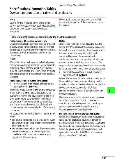
Note: Causes for the reduction in the short-circuit current-carrying capacity can be: Reduction of the conductor cross-section, other conductor insulation.
Short-circuit protection must not be provided where an interruption of the circuit could prove hazardous.
Protection of the phase conductors and the neutral conductor
Protection of the phase conductorsOvercurrent protection devices must be provided in every phase conductor: they must disconnect the conductor in which the overcurrent occurs, but not necessarily also disconnect the other live conductors. Note: Where the disconnection of an individual phase conductor could prove hazardous, as for example, with three-phase motors, suitable precautions must be taken. Motor-protective circuit-breakers and circuit-breakers disconnect in three poles as standard.
Protection of the neutral conductor:1. In installations with directly earthed neutral
point (TN or TT systems)Where the cross-section of the neutral conductor is less than that of the phase conductors, an overcurrent monitoring device appropriate to its cross-section is to be provided in the neutral conductor; this overcurrent monitoring device must result in the disconnection of the phase conductors but not necessarily that of the neutral conductor.An overcurrent monitoring device is not necessary where:• the neutral conductor is protected in the event
of a short circuit by the protective device for the phase conductors
• the largest current which can flow through the neutral conductor is, in normal operation, considerably less than the current-carrying capacity of this conductor.
Note: This second condition is met provided that the power transferred is divided as evenly as possible among the phase conductors, for example where the total power consumption of the load connected between phase and neutral conductors, lamps and sockets is much less than the total power transferred via the circuit. The cross-section of the neutral conductor must not be less than the values in the table on the next page.2. In installations without a directly earthed
neutral point (IT system)Where it is necessary for the neutral conductor to be included, an overcurrent monitoring device must be provided in the neutral conductor of each circuit, to cause disconnection of all live conductors in the relevant circuit (including the neutral conductor).The overcurrent monitoring device may however be omitted where the neutral conductor in question is protected against short circuit by an upstream protective device, such as in the incoming section of the installation.
Disconnection of the neutral conductorWhere disconnection of the neutral conductor is specified, the protective device used must be designed in such a way that the neutral conductor cannot under any circumstances be disconnected before the phase conductors and reconnected again after them. 4-pole NZM circuit-breakers always meet these conditions.
9-45

Specifications, Formulae, Tables
Overcurrent protection of cables and conductors
Moeller W
iring Manual 02/05
9-46
9
Current-carrying capacity and protection of cables and conductors with
NYY, NYCWY, NYKY, NYM, NYMZ, NYMT, NYBUY, NHYRUZY
E
n In free air
ter
2 3it). Circuit-breakers and overcurrent protective devices with applies:
� 0.3 d
�
� 0.3 d
�
PVC insulation to DIN VDE 0298-4, at 25 °C ambient temperature
Type of cable or conductor
NYM, NYBUY, NHYRUZY, NYIF,H07V-U, H07V-R, H07V-K, NYIFY
Type of installation
A1 B1 B2 COn or under the wall surface, under plaster
In heat-insulating walls, in conduit under the surface
In electrical conduit or cable channel
Installed directly ithe wall
Single-core cable Multi-core cable
Multi-core cable under the surface
Single wires in conduit on the wall surface
Multi-core cable in conduit on the wall surface or on the floor
Multi-core cable Spur wiring in thewall or under plas
Number of cores 2 3 2 3 2 3 2 3Current-carrying capacity Iz in A at 25 °C ambient temperature and 70 °C operating temperature. The selection of overcurrent protective devices is governed in general by conditions Ib F In F Iz and I2 F 1.45 Iz. For overcurrent protection devices with a tripping current of I2 F In only apply the condition:
Ib F In F Iz (Ib: operating current of the circuswitch-disconnectors fulfil this condition. For other tripping currents, the following formula
In F ; = 1.45
x---------- In⋅
Iz
In

Specifications, Formulae, TablesOvercurrent protection of cables and conductors
Moeller Wiring Manual 02/05
9
(con
tinue
d)
Type
of
inst
alla
tion
A1B1
B2C
E
Num
ber o
f co
res
23
23
23
23
23
Cros
s se
ctio
n Cu
co
nduc
tor
in m
m2
I zI n
I zI n
I zI n
I zI n
I zI n
I zI n
I zI n
I zI n
I zI n
I zI n
1.5
16.5
1614
1318
.516
16.5
1616
.516
1513
2120
18.5
1621
2019
.516
2.5
2120
1916
2525
2220
2220
2020
2825
2525
2925
2725
428
2525
2534
3230
2530
2528
2537
3535
3539
3536
35
636
3533
3243
4038
3539
3535
3549
4043
4051
5046
40
1049
4045
4060
5053
5053
5050
5067
6363
6370
6364
63
1665
6359
5081
8072
6372
6365
6390
8081
8094
8085
80
2585
8077
6310
710
094
8095
8082
8011
910
010
210
012
512
510
710
0
3510
510
094
8013
312
511
810
011
710
010
110
014
612
512
612
515
412
513
412
5
5012
612
511
410
016
016
014
212
5–
––
––
––
––
––
–
7016
016
014
412
520
420
018
116
0–
––
––
––
––
––
–
9519
316
017
416
024
620
021
920
0–
––
––
––
––
––
–
120
223
200
199
160
285
250
253
250
––
––
––
––
––
––
For o
verc
urre
nt p
rote
ctiv
e de
vice
s w
hose
rate
d cu
rrent
In d
oes
not c
onfo
rm to
the
valu
es g
iven
in th
e ta
ble,
sel
ect t
he n
ext l
ower
ava
ilabl
e ra
ted
curre
nt v
alue
.
9-47

Specifications, Formulae, TablesOvercurrent protection of cables and conductors
Moeller Wiring Manual 02/05
9
Minimum cross section for protective conductors to DIN VDE 0100-510 (1987-06, t), DIN VDE 0100-540 (1991-11)
Protective conductor or PEN conductor 1)
Protective conductor 3) laid seperately
Phase conductor
Insulated power cables
0.6/1-kV cable with 4 conductors
Protected Unprotected 2)
mm2 mm2 mm2 mm2 Cu Al
mm2 Cu
to 0.5 0.5 – 2.5 4 4
0.75 0.75 – 2.5 4 4
1 1 – 2.5 4 4
1.5 1.5 1.5 2.5 4 4
2.5 2.5 2.5 2.5 4 4
4 4 4 4 4 4
6 6 6 6 6 6
10 10 10 10 10 10
16 16 16 16 16 16
25 16 16 16 16 16
35 16 16 16 16 16
50 25 25 25 25 25
70 35 35 35 35 35
95 50 50 50 50 50
120 70 70 70 70 70
150 70 70 70 70 70
185 95 95 95 95 95
240 – 120 120 120 120
300 – 150 150 150 150
400 – 185 185 185 185
1) PEN conductor f 10 mm2 Cu or 18 mm2 Al.2) It is not permissible to lay aluminium conductors without protection.3) With phase conductors of f 95 mm2 or more, it is advisable to use non-insulted conductors
9-48

Specifications, Formulae, TablesOvercurrent protection of cables and conductors
Moeller Wiring Manual 02/05
9
Conversion factors
When the ambient temperature is not 30 °C; to be used for the current-carrying capacity of wiring or cables in air to VDE 0298 Part 4
*) Higher ambient temperatures in accordance with information given by the manufacturer
Insulation material*) NR/SR PVC EPR
Permissible operational temperature 60 °C 70 °C 80 °C
Ambient temperature °C Conversion factors
10 1.29 1.22 1.18
15 1.22 1.17 1.14
20 1.15 1.12 1.10
25 1.08 1.06 1.05
30 1.00 1.00 1.00
35 0.91 0.94 0.95
40 0.82 0.87 0.89
45 0.71 0.79 0.84
50 0.58 0.71 0.77
55 0.41 0.61 0.71
60 – 0.50 0.63
65 – – 0.55
70 – – 0.45
9-49

Specifications, Formulae, TablesOvercurrent protection of cables and conductors
Moeller Wiring Manual 02/05
9
Converstion factors to VDE 0298 part 4
Grouping of several circuits
Arrangement Number of circuits
1 2 3 4 6 9 12 1516
20
1 Embedded or enclosed
1.00 0.80 0.70 0.700.65
0.550.57
0.50 0.45 0.400.41
0.400.38
2 Fixed to walls or floors
1.00 0.85 0.800.79
0.75 0.700.72
0.70 – – –
3 Fixed to ceilings 0.95 0.800.81
0.700.72
0.700.68
0.650.64
0.600.61
– – –
4 Fixed to cable trays arranged horizontally or vertically
1.000.970.90
0.870.80
0.770.75
0.730.75
0.720.70 – – –
5 Fixed to cable trays or consoles
1.00 0.840.85
0.830.80
0.810.80
0.790.80
0.780.80
– – –
9-50

Moeller Wiring Manual 02/05
Specifications, Formulae, TablesElectrically critical equipment of machines
9
Extract from IEC/EN 60204-1: (VDE 0113 part 1)
This world wide binding standard is used for the electrical equipment of machines, provided that for the type of machine to be equipped there is no product standard (Type C).Safety requirements regarding the protection of personnel, machines and material according to the European Machinery Directive are stressed under the heading “Safety of machines”. The degree of possible danger is to estimated by risk assessment (EN 1050). The Standard also includes requirements for equipment, engineering and construction, as well as tests to ensure faultless function and the effectiveness of protective measures.The following paragraphs are an extract from the Standard.
Mains isolating device (main switches)Every machine must be equipped with a manually-operated main switch, henceforth referred to as a mains isolating device. It must be possible to isolate the entire electrical equipment of the machine from the mains using the mains isolating device. The breaking capacity
must be sufficient to simultaneously disconnect the stalled current of the largest motor in the machine and the total current drawn by all the other loads in normal operation. Its Off position must be lockable and must not be indicated until the specified clearances and creepage distances between all contacts have been achieved. It must have only one On and one Off position with associated stops. Star-delta, reversing and multi-speed switches are not permissible for use as mains isolating devices.The tripped position of circuit-breakers is not regarded as a switch position, therefore there is no restriction on their use as mains isolating devices.Where there are several incomers, each one must have a mains isolating device. Mutual interlocking must be provided where a hazard may result from only one mains isolating device being switched off. Only circuit-breakers may be used as remotely-operated switches. They must be provided with an additional handle and be lockable in the Off position.
Protection against electric shock
The following measures must be taken to protect personnel against electric shock:
Protection against direct contactThis is understood as meaning protection by means of an enclosure which can only be opened by qualified personnel using a key or special tool. Such personnel is not obliged to disable the mains isolating device before opening the enclosure, Live parts must be protected against direct contact in accordance with IEC 50274 or VDE 0660 part 514. Where the mains isolating device is interlocked with the door, the restrictions mentioned in the previous paragraph cease to apply because the door can only be opened when the mains isolating device is switched off. It is permissible for an interlock to be removable by an electrician using a tool, e.g. in order to search for a fault. Where an
interlock has been removed, it must still be possible to switch off the mains isolating device.Where it is possible for an enclosure to be opened without using a key and without disconnection of the mains isolating device, all live parts must at the very least comply with IP 2X or IP XXB degree of protection in accordance with IEC/EN 60529.
Protection against indirect contactThis involves prevention of a dangerous touch voltage resulting from faulty insulation. To meet this requirement, protective measures in accordance with IEC 60364 or VDE 0100 must be used. An additional measure is the use of protective insulation (protection class II) to IEC/EN 60439-1 or VDE 0660 Part 500.
9-51

Specifications, Formulae, TablesElectrically critical equipment of machines
Moeller Wiring Manual 02/05
9
Protection of equipment
Protection in the event of power failureWhen the power returns following a failure in the supply, machines or parts of machines must not start automatically where this would result in a dangerous situation or damage to property. With contactor controls this requirement can easily be met via self-maintaining circuits.For circuits with two-wire control, an additional contactor relay with three-wire control in the supply to the control circuit can carry out this function. Mains isolating devices and motor-protective circuit-breakers with undervoltage releases also reliably prevent automatic restarting on return of voltage.
Overcurrent protectionNo overcurrent protective device is normally required for the mains supply cable. Overcurrent protection is provided by the protective device at the head of the incoming supply. All other circuits must be protected by means of fuses or circuit-breakers. The stipulation for fuses is that replacement must be freely obtainable in the country in which the fuses are used. This difficulty can be avoided by using circuit-breakers, with the added benefits of disconnection in all poles, rapid operational readiness and prevention of single-phasing.
Overload protection of motorsContinously operating motors above 0.5 kW must be protected against overload. Overload protection is recommended for all other motors. Motors which are frequently starting and braking are difficult to protect and often require a special protective device. Built-in thermal sensors are particularly suitable for motors with restricted cooling. In addition, the fitting of overload relays is always recommended, particularly as protection by stalled rotor.
9-52

Specifications, Formulae, TablesElectrically critical equipment of machines
Moeller Wiring Manual 02/05
9
Control functions in the event of a fault
A fault in the electrical equipment must not result in a dangerous situation or in damage. Suitable measures must be taken to prevent danger from arising. The expense of using appropriate measures can be extremely high if applied generally. To permit a better assessment of the magnitude of the risk in conjunction with the respective application, the Standard EN 954-1 has been published:„Safety-related parts of control systems Part 1: General rules for design“.The use of risk assessment to EN 954-1 is dealt with in the Moeller manual “Safety Specifications for Machines and Plant” (Order No. TB 0-009).
Emergency-Stop deviceEvery machine which could potentially cause danger must be equipped with an Emergency-Stop device which, in a main circuit may be an Emergency-Stop switch, and in a control circuit an Emergency-Stop control circuit device.Actuation of the Emergency-Stop device must result in all current loads which could directly result in danger, being disconnected by de-energization via another device or circuit, i.e. electromechanical devices such as contactors, contactor relays or the undervoltage release of the mains isolating device.For direct manual operation, Emergency-Stop control circuit devices must have a mushroom-head push-button and positively opening contacts. Once the Emergency-Stop control circuit device has been actuated, it must only be possible to restart the machine after local resetting. Resetting alone must not allow restarting.
Furthermore, the following apply for both Emergency-Stop switch and Emergency control circuit device:• The handle must be red with a yellow
background• Emergency-Stop devices must be quickly and
easily accessible in the event of danger• The Emergency-Stop function must take
precedence over all other functions and operations
• It must be possible to determine functional capability by means of tests, especially in severe environmental conditions
• Where there is separation into several Emergency-Stop areas, it must be clearly discernible to which area an Emergency-Stop device applies
Emergency operationsThe term Emergency-Stop is short and concise, and should continue to be used for general usage.It is not clear however from the term Emergency-Stop which functions are carried out with this. In order to be able to give a more precise definition here, IEC/EN 60204-1 describes under the generic term “Emergency operations” two specific functions:1. Emergency-StopThis involves the possibility of stopping dangerous motions as quickly as possible.2. Emergency-Off Where there is a risk of an electric shock by direct contact, e.g. with live parts in electrical operating areas, then an Emergency-Off device shall be provided.
9-53

Specifications, Formulae, TablesElectrically critical equipment of machines
Moeller Wiring Manual 02/05
9
Colours of push-buttons and their meanings
To IEC/EN 60073, VDE 0199, IEC/EN 60204-1 (VDE 0113 Part 1)
Colour Meaning Typical application
RED Emergency • Emergency-Stop• Fire fighting
YELLOW Abnormal condition Intervention, to suppress abnormal conditions or to avoid unwanted changes
GREEN Safe condition Start from safe conditon
BLUE Enforced action Resetting function
WHITE No specific meaning assigned • Start/ON (preferred)• Stop/OFF
GREY • Start/ON• Stop/OFF
BLACK • Start/ON• Stop/Off (preferred)
9-54

Specifications, Formulae, TablesElectrically critical equipment of machines
Moeller Wiring Manual 02/05
9
Colours of indicator lights and their meanings
To IEC/EN 60073, VDE 0199, IEC/EN 60204-1 (VDE 0113 Part 1)
Colours of illuminated push-buttons and their meanings
Both tables are valid for illuminated push-buttons, Table 1 relating to the function of the actuators.
Colour Meaning Explanation Typical application
RED Emergency Warning of potential danger or a situation which requires immediate action
• Failure of pressure in the lubricating system
• Temperature outside specified (safe) limits
• Essential equipment stopped by action of a protective device
YELLOW Abnormal condition
Impending critical condition • Temperature (or pressure) different from normal level
• Overload, which is permissible for a limited time
• Resetting
GREEN Safe condition
Indication of safe operating conditions or authorization to proceed, clear way
• Cooling liquid circulating• Automatic tank control
switched on • Machine ready to be started
BLUE Enforced action
Operator action essential • Remove obstacle• Switch over to Advance
WHITE No specific meaning assigned (neutral)
Every meaning: may be used whenever doubt exists about the applicability of the colours RED, YELLOW or GREEN; or as confirmation
• Motor running• Indication of operating
modes
9-55
Moeller Wiring Manual 02/05
9
Specifications, Formulae, TablesMeasures for risk reduction
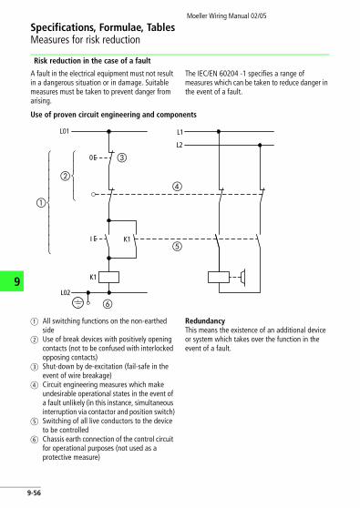
Risk reduction in the case of a fault
A fault in the electrical equipment must not result in a dangerous situation or in damage. Suitable measures must be taken to prevent danger from arising.
The IEC/EN 60204 -1 specifies a range of measures which can be taken to reduce danger in the event of a fault.
Use of proven circuit engineering and components
a All switching functions on the non-earthed side
b Use of break devices with positively opening contacts (not to be confused with interlocked opposing contacts)
c Shut-down by de-excitation (fail-safe in the event of wire breakage)
d Circuit engineering measures which make undesirable operational states in the event of a fault unlikely (in this instance, simultaneous interruption via contactor and position switch)
e Switching of all live conductors to the device to be controlled
f Chassis earth connection of the control circuit for operational purposes (not used as a protective measure)
RedundancyThis means the existence of an additional device or system which takes over the function in the event of a fault.
L01
0
K1
K1I
⎧⎪⎪⎪⎪⎨⎪⎪⎪⎪⎩
⎧⎪⎨⎪⎩
L1
L2
L02
�
�
�
�
�
�
9-56

Moeller Wiring Manual 02/05
Specifications, Formulae, TablesMeasures for risk avoidance
9
Diversity
The construction of control circuits according to a range of function principles or using various types of device.
a Functional diversity by combination of normally open and normally break contacts
b Diversity of devices due to use of various types of device (here, various types of contactor relay)
c Safety barrier open d Feedback circuit e Safety barrier closed
Function testsThe correct functioning of the equipment can be tested either manually or automatically.
c
ed
K1 K2
K1
K2
13
14
21
22
a
b
9-57
Moeller Wiring Manual 02/05
9
Specifications, Formulae, TablesDegrees of protection for electrical equipment
Degrees of protection for electrical equipment by enclosures, covers and similar to IEC/EN 60529 (VDE 0470 part 1)
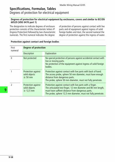
The designation to indicate degrees of enclosure protection consists of the characteristic letters IP (Ingress Protection) followed by two characteristic numerals. The first numeral indicates the degree
of protection of persons against contact with live parts and of equipment against ingress of solid foreign bodies and dust, the second numeral the degree of protection against the ingress of water.
Protection against contact and foreign bodies
First numeral
Degree of protection
Description Explanation
0 Not protected No special protection of persons against accidental contact with live or moving parts. No protection of the equipment against ingress of solid foreign bodies.
1 Protection against solid objects f 50 mm
Protection against contact with live parts with back of hand. The access probe, sphere 50 mm diameter, must have enough distance from dangerous parts. The probe, sphere 50 mm diameter, must not fully penetrate.
2 Protection against solid objects f 12,5 mm
Protection against contact with live parts with a finger.The articulated test finger, 12 mm diameter and 80 mm length, must have suffient distance from dangerous parts. The probe, sphere 12,5 mm diameter, must not fully penetrate.
9-58

Specifications, Formulae, TablesDegrees of protection for electrical equipment
Moeller Wiring Manual 02/05
9
Protection against contact and foreign bodies
First numeral
Degree of protection
Description Explanation
3 Protection against solid objects f 2.5 mm
Protection against contact with live parts with a tool.The entry probe, 2,5 mm diameter, must not penetrate.The probe, 2,5 mm diameter, must not penetrate.
4 Protection against solid objects f 1 mm
Protection against contact with live parts with a wire.The entry probe, 1,0 mm diameter, must not fully penetrate.The probe, 1,0 mm diameter, must not penetrate.
5 Protection against accumulation of dust
Protection against contact with live parts with a wire.The entry probe, 1,0 mm diameter, must not penetrate.The ingress of dust is not totally prevented, but dust does not enter in sufficient quantity to interfere with satisfactory opera-tion of the equipment or with safety.
6 Protection against the ingress of dust
Dust-tight
Protection against contact with live parts with a wire.The entry probe, 1,0 mm diameter, must not penetrate.No entry of dust.
Example for stating degree of protection: IP 4 4
Characteristic letterFirst numeralSecond numeral
9-59

Specifications, Formulae, TablesDegrees of protection for electrical equipment
Moeller Wiring Manual 02/05
9
Protection against water
Second numeral
Degree of protection
Description Explanation
0 Not protected No special protection
1 Protected against vertically dripping water
Dripping water (vertically falling drops) shall have no harmful effect.
2 Protected against dripping water, when enclosure tilted up to 15°
Dripping water shall have no harmful effect when the enclosure is tilted at any angle up to 15° from the vertical.
3 Protected against sprayed water
Water falling as a spray at any angle up to 60° from the vertical shall have no harmful effect.
4 Protected against splashing water
Water splashed against the enclosure from any direction shall have no harmful effect.
5 Protected against water jets
Water projected by a nozzle against the equipment from any direction shall have no harmful effect.
6 Protected against powerful water jets
Water projected in powerful jets against the enclosure from any direction shall have no harmful effect.
7 Protected against the effects of occasional submersion
Ingress of water in harmful quantities shall not be possible when the enclosure is immersed in water under defined conditions of pressure and time.
9-60

Specifications, Formulae, TablesDegrees of protection for electrical equipment
Moeller Wiring Manual 02/05
9
8 Protected against the effects of submersion
Ingress of water in harmful quantities must not be possible when the equipment is continuously submerged in water under conditions which are subject to agreement between manufacturer and user.These conditions must be more stringent than those for characteristic numeral 7.
9K* Protected during cleaning using high-pressure/steam jets
Water which is directed against the enclosure under extremely high pressure from any direction must not have any harmful effects.Water pressure of 100 barWater temperature of 80 °C
* This characteristic numeral originates from DIN 40050 -9.
Second numeral
Degree of protection
Description Explanation
9-61

Specifications, Formulae, TablesDegrees of protection for electrical equipment
Moeller Wiring Manual 02/05
9
Degree of protection for electrical equipment for USA and Canada to IEC/EN 60529 (VDE 0470 part 1)
The IP ratings quoted in the table represent a rough comparison only. A precise comparison is
not possible since the degree of protection tests and the evaluation criteria differ.
Designation of the enclosure and the degree of protection
Designation of the enclosure and the degree of protection to CSA-C22.1, CSA-C22.2 NO. 0.1-M1985 (R1999)3)
Comparable IP degree of protection to IEC/EN 60529 DIN 40050to NEC NFPA 70
(National Electrical Code) to UL 50 to NEMA 250-1997
to NEMA ICS 6-1993 (R2001)1) to EEMAC E 14-2-19932)
Enclosure type 1 Enclosure type 1General purpose
Enclosure 1Enclosure for general purpose
IP20
Enclosure type 2Drip-tight
Enclosure type 2Drip-proof
Enclosure 2Drip-proof enclosure
IP22
Enclosure type 3Dust-tight, rain-tight
Enclosure type 3Dust-tight, rain-tight, resistant to sleet and ice
Enclosure 3Weather-proof enclosure
IP54
Enclosure type 3 RRain-proof
Enclosure type 3 RRain-proof, resistant to sleet and ice
Enclosure type 3 SDust-tight, rain-tight
Enclosure type 3 SDust-tight, rain-tight, resistant to sleet and ice
Enclosure type 4Rain-tight, water-tight
Enclosure type 4Dust-tight, water-tight
Enclosure 4Water-tight enclo-sure
IP65
9-62

Specifications, Formulae, TablesDegrees of protection for electrical equipment
Moeller Wiring Manual 02/05
9
1) NEMA = National Electrical Manufacturers Association
2) EEMAC = Electrical and Electronic Manufac-turers Association of Canada
3) CSA = Canadian Electrical Code, Part I (19th Edition), Safety Standard for Electrical Instal-lations
Enclosure type 4 XRain-tight, water-tight, corrosion-resistant
Enclosure type 4 XDust-tight, water-tight, corrosion-resistant
IP65
Enclosure type 6Rain-tight
Enclosure type 6Dust-tight, water-tight, immersible, resistant to sleet and ice
Enclosure type 6 PRain-tight, corrosion-resistant
Enclosure type 11Drip-tight, corrosion-resistant
Enclosure type 11Drip-tight, corrosion-resistant, oil-immersed
Enclosure type 12Dust-tight, drip-tight
Enclosure type 12For use in industry, drip-tight, dust-tight
Enclosure 5Dust-tight enclosure
IP54
Enclosure type 12 K(As for type 12)
Enclosure type 13Dust-tight, drip-tight
Enclosure type 13Dust-tight, oil-tight
Designation of the enclosure and the degree of protection
Designation of the enclosure and the degree of protection to CSA-C22.1, CSA-C22.2 NO. 0.1-M1985 (R1999)3)
Comparable IP degree of protection to IEC/EN 60529 DIN 40050to NEC NFPA 70
(National Electrical Code) to UL 50 to NEMA 250-1997
to NEMA ICS 6-1993 (R2001)1) to EEMAC E 14-2-19932)
9-63

Specifications, Formulae, TablesDegrees of protection for electrical equipment
Moeller Wiring Manual 02/05
9
9-64

NotesMoeller Wiring Manual 02/05
9
9-65
Specifications, Formulae, TablesDegrees of protection for electrical equipment
Moeller Wiring Manual 02/05
9
Abnorm
Break Make
c c
0.9 1 1 0.9 –
0.65 1 1 0.65 10
0.3 1 1 0.3 6
0.3 1 1 0.3 10
t0,95 t0,95
1 ms 1 1 1 ms –
6 x P1) 1 1 6 x P1) 1.16 x P1)
15 ms 1 1 15 ms 10
1) The value “6 x P” results from an empirical relato an upper limit of P = 50 W, i.e. 6 [ms]/[W] = 300than 50 W are assumed to consist of smaller loadslimit, irrespective of the power consumption.
I
Ie
U
Ue
I
Ie
I
Ie
U
Ue
I
Ie
Type of current
Utilisation catorgory
Typical examples of application Normal conditions of use
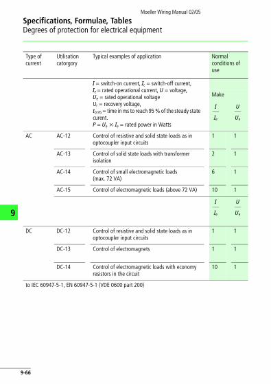
I = switch-on current, Ic = switch-off current,Ie = rated operational current, U = voltage,Ue = rated operational voltageUr = recovery voltage,t0.95 = time in ms to reach 95 % of the steady state curent.P = Ue x Ie = rated power in Watts
Make
AC AC-12 Control of resistive and solid state loads as in optocoupler input circuits
1 1
AC-13 Control of solid state loads with transformer isolation
2 1
AC-14 Control of small electromagnetic loads (max. 72 VA)
6 1
AC-15 Control of electromagnetic loads (above 72 VA) 10 1
DC DC-12 Control of resistive and solid state loads as in optocoupler input circuits
1 1
DC-13 Control of electromagnets 1 1
DC-14 Control of electromagnetic loads with economy resistors in the circuit
10 1
to IEC 60947-5-1, EN 60947-5-1 (VDE 0600 part 200)
I
Ie
U
Ue
I
Ie
U
Ue
9-66

Specifications, Formulae, TablesDegrees of protection for electrical equipment
Moeller Wiring Manual 02/05
f application Normal condi-tions of use
nt, Ic = switch-off current,nal current, U = voltage,nal voltagege,reach 95 % of the steady state
d power in Watts
Make
and solid state loads as in ircuits
1 1
e loads with transformer isola- 2 1
ctromagnetic loads (max. 72 6 1
agnetic loads (above 72 VA) 10 1
and solid state loads as in ircuits
1 1
agnets 1 1
agnetic loads with economy uit
10 1
200)
I
Ie
U
Ue
I
Ie
U
Ue
9Abnormal conditions of use
Break Make Break
c c c c
0.9 1 1 0.9 – – – – – –
0.65 1 1 0.65 10 1.1 0.65 1.1 1.1 0.65
0.3 1 1 0.3 6 1.1 0.7 6 1.1 0.7
0.3 1 1 0.3 10 1.1 0.3 10 1.1 0.3
t0,95 t0,95 t0,95 t0,95
1 ms 1 1 1 ms – – – – – –
6 x P1) 1 1 6 x P1) 1.16 x P1)
1.1 6 x P1) 1.1 1.1
15 ms 1 1 15 ms 10 1.1 15 ms 10 1.1 15 ms
1) The value “6 x P” results from an empirical relationship that represents most DC magnetic loads to an upper limit of P = 50 W, i.e. 6 [ms]/[W] = 300 [ms]. Loads having a power consumption greater than 50 W are assumed to consist of smaller loads in parallel. Therefore, 300 ms is to be an upper limit, irrespective of the power consumption.
I
Ie
U
Ue
I
Ie
U
Ue
I
Ie
U
Ue
I
Ie
U
Ue
I
Ie
U
Ue
I
Ie
U
Ue
9-67

Moeller Wiring Manual 02/05
9
Specifications, Formulae, TablesNorth American classification for control switches
Switching capacity
Rated voltage V Make A Break A
120240480600
60301512
631.51.2
120240480600
30157.56
31.50.750.6
120240480600
157.53.753
1.50.750.3750.3
120240
3.61.8
0.60.3
125250301 to 600
2.21.10.4
2.21.10.4
125250301 to 600
1.10.550.2
1.10.550.2
125250301 to 600
0.550.270.10
0.550.270.10
125250301 to 600
0.220.11–
0.220.11–
Classification DesignationAt maximum rated voltage of
Thermal uninterrupted current
AC 600 V 300 V 150 V A
Heavy Duty A600A600A600A600
A300A300––
A150–––
10101010
Standard Duty B600B600B600B600
B300B300––
B150–––
5555
C600C600C600C600
C300C300––
C150–––
2.52.52.52.5
––
D300D300
D150–
11
DC
Heavy Duty N600N600N600
N300N300–
N150––
101010
Standard Duty P600P600P600
P300P300–
P150––
555
Q600Q600Q600
Q300Q300–
Q150––
2.52.52.5
–––
R300R300–
R150––
1.01.0–
to UL 508, CSA C 22.2-14 and NEMA ICS 5
9-68

Specifications, Formulae, TablesNorth American classification for control switches
Moeller Wiring Manual 02/05
d voltage ofThermal unin-terrupted cur-rent
300 V 150 V A
A300A300––
A150–––
10101010
B300B300––
B150–––
5555
C300C300––
C150–––
2.52.52.52.5
D300D300
D150–
11
N300N300–
N150––
101010
P300P300–
P150––
555
Q300Q300–
Q150––
2.52.52.5
R300R300–
R150––
1.01.0–
9
Switching capacity
Rated voltage V Make A Break A Make VA Break VA
120240480600
60301512
631.51.2
7200720072007200
720720720720
120240480600
30157.56
31.50.750.6
3600360036003600
360360360360
120240480600
157.53.753
1.50.750.3750.3
1800180018001800
180180180180
120240
3.61.8
0.60.3
432432
7272
125250301 to 600
2.21.10.4
2.21.10.4
275275275
275275275
125250301 to 600
1.10.550.2
1.10.550.2
138138138
138138138
125250301 to 600
0.550.270.10
0.550.270.10
696969
696969
125250301 to 600
0.220.11–
0.220.11–
2828–
2828–
9-69

Moeller Wiring Manual 02/05
9
Specifications, Formulae, TablesUtilisation categories for contactors
Verification of s
Break Make
c c
0.95 1 1 0.95 All val-ues
1
0.65 2.5 1 0.65 All val-ues
4
0.650.35
11
0.170.17
0.650.35
Ie F 100Ie > 100
88
0.650.35
66
11
0.650.35
Ie F 100Ie > 100
1010
3
1.)
1
8
6
6
8
Ic
Ie
Ur
Ue
Ie
A
I
I
Type of current
Utilisation category
Typical examples of applicationI = switch-on current, Ic = switch-off current, Ie = rated operational current, U = voltage, Ue = rated operational voltageUr = recovery voltage
Verification of electrical lifespan
Make
AC AC-1 Non-inductive or slightly inductive loads, resistance furnaces
All val-ues
1 1
AC-2 Slip-ring motors: starting, switch-off All val-ues
2.5 1
AC-3 Squirrel-cage motors: stating, switch-off, switch-off during running4)
Ie F 17Ie > 17
66
11
AC-4 Sqirrel-cage motors: starting, plugging, reversing, inching
Ie F 17Ie > 17
66
11
AC-5A Switching of electric discharge lamp controls
AC-5B Switching of incandescent lamps
AC-6A3) Switching of transformers
AC-6B3) Switching of capacitor banks
AC-7A Slightly inductive loads in household appliances and similar applications
Data as supplied by the manufacturer
AC-7B Motor load for household appliances
AC-8A Switching of hermetically enclosed refrigerant compressor motors with manual reset of overload releases5)
AC-8B Switching of hermetically enclosed refrigerant compressor motors with automatic reset of overload releases5)
AC-53a Switching of squirrel-cage motor with semi-conductor contactors
Ie
A
I
Ie
U
Ue
9-70

Specifications, Formulae, TablesUtilisation categories for contactors
Moeller Wiring Manual 02/05
pplication t,current,
al voltage
Verification of electri-cal lifespan
Make
htly inductive loads, All val-ues
1 1
ing, switch-off All val-ues
2.5 1
stating, switch-off, ning4)
Ie F 17Ie > 17
66
11
tarting, plugging, Ie F 17Ie > 17
66
11
discharge lamp controls
scent lamps
mers
r banks
ds in household appli-lications
Data as sup-plied by the manufacturer
hold appliances
ally enclosed refriger-rs with manual reset of
ally enclosed refriger-rs with automatic reset
cage motor with ctors
Ie
A
I
Ie
U
Ue
9
Verification of switching capacity
Break Make Break
c c c c
0.95 1 1 0.95 All values
1.5 1.05 0.8 1.5 1.05 0.8
0.65 2.5 1 0.65 All values
4 1.05 0.65 4 1.05 0.8
0.650.35
11
0.170.17
0.650.35
Ie F 100Ie > 100
88
1.051.05
0.450.35
88
1.051.05
0.450.35
0.650.35
66
11
0.650.35
Ie F 100Ie > 100
1010
1.051.05
0.450.35
1010
1.051.05
0.450.35
3.0 1.05 0.45 3.0 1.05 0.45
1.52)
1.052) 1.52)
1.052)
1.5 1.05 0.8 1.5 1.05 0.8
8.0 1.051) 8.0 1.051)
6.0 1.051) 6.0 1.051)
6.0 1.051) 6.0 1.051)
8.0 1.05 0.35 8.0 1.05 0.35
Ic
Ie
Ur
Ue
Ie
A
I
Ie
U
Ue
Ic
Ie
Ur
Ue
9-71

Specifications, Formulae, TablesUtilisation categories for contactors
Moeller Wiring Manual 02/05
9
Verification of sw
Break Make
L/R ms
L/R ms
1 1 1 1 All values 1
2 2.5 1 2 All values 4
7.5 2.5 1 7.5 All values 41
2)
4) Devices for utilization category AC-3 may be useperiod such as for setting up a machine; duringmust not exceed a total of five per minute or m
5) Hermetically enclosed refrigerant compressor mmotor both of which are housed in the same encrunning in the refrigerant.
Ic
Ie
Ur
Ue
Ie
A I
Type of current
Utilization category
Typical examples of applicationI = switch-on current, Ic = switch-off current,Ie = rated operational current, U = voltage,Ue = rated operational voltage, Ur = recovery voltage
Verification of electrical endurance
Make
DC DC-1 Non-inductive or slightly inductive loads, resistance furnaces
All values 1 1
DC-3 Shunt motors: starting, plugging, reversing, inching, dynamic braking
All values 2.5 1
DC-5 Series motors: starting, plugging, reversing, inching, dynamic braking
All values 2.5 1
DC-6 Switching of incandescent lamps
To IEC/EN 60 947-4-1, VDE 0660 Part 102
1) c = 0.45 for Ie F 100 A; c = 0.35 for Ie > 100 A.2) Tests must be carried out with an incandescent lamp load connected.3) Here, the test data are to be derived from the AC-3 or AC-4 test values in accordance with TableVIIb,
IEC/EN 60 947-4-1.
Ie
A
I
Ie
U
Ue
9-72

Specifications, Formulae, TablesUtilisation categories for contactors
Moeller Wiring Manual 02/05
pplication
,current,
l voltage,
Verification of electrical endurance
Make
tly inductive loads, All values 1 1
, plugging, revers-braking
All values 2.5 1
, plugging, revers-braking
All values 2.5 1
cent lamps
100 A.mp load connected.or AC-4 test values in accordance with TableVIIb,
Ie
A
I
Ie
U
Ue
9
Verification of switching capacity
Break Make Break
L/R ms
L/R ms
L/R ms
L/R ms
1 1 1 1 All values 1.5 1.05 1 1.5 1.05 1
2 2.5 1 2 All values 4 1.05 2.5 4 1.05 2.5
7.5 2.5 1 7.5 All values 41.5
1.051.05
15 41.52)
1.051.052)
15
2) 2)
4) Devices for utilization category AC-3 may be used for occasional inching or plugging during a limited period such as for setting up a machine; during this limited time period, the number of operations must not exceed a total of five per minute or more than ten in a ten minute period.
5) Hermetically enclosed refrigerant compressor motor means a combination of a compressor and a motor both of which are housed in the same enclosure with no external shaft or shaft seals, the motor running in the refrigerant.
Ic
Ie
Ur
Ue
Ie
A
I
Ie
U
Ue
Ic
Ie
Ur
Ue
9-73

Moeller Wiring Manual 02/05
9
Specifications, Formulae, TablesUtilisation categories for switch-disconnectors
Verification
Break Make
c c
1) 1) 1) 1) 1) All val-ues
1 0.95 1 1 0.95 All val-ues
1 0.8 1 1 0.8 All val-ues
1 0.65 1 1 0.65 Ie F100Ie > 100
L/Rms
L/Rms
1) 1) 1) 1) 1) All val-ues
1 1 1 1 1 All val-ues
1 2 1 1 2 All val-ues
1 7.5 1 1 7.5 All val-ues
U
Ue
Ic
Ie
Ur
Ue
Ie
A
U
Ue
Ic
Ie
Ur
Ue
Ie
A
Type of current
Utilisation category
Typical examples of applicationI = switch-on current,Ic = switch-off current,Ie = rated operational current,U = voltage,Ue = rated operational voltage,Ur = recovery voltage
Verification of electrical endurance
Make
AC AC-20 A(B)2) Making and breaking without load All values 1)
AC-21 A(B)2) Switching resistive loads including low overloads All values 1
AC-22 A(B)2) Switching mixed resistive and inductive loads including low overloads
All values 1
AC-23 A(B)2) Switching motors and other highly inductive loads
All values 1
DC DC-20 A(B)2) Making and breaking without load All values 1)
DC-21 A(B)2) Switching resistive loads including low overloads All values 1
DC-22 A(B)2) Switching mixed resistive and inductive loads, including low overloads (e.g. shunt motors)
All values 1
DC-23 A(B)2) Switching highly inductive loads (e.g. series motors)
All values 1
For load-break switches, switch-disconnectors and switch-fuse units to IEC/EN 60947-3 (VDE 0660 part 107) 1) If the switching device has a making and/or breaking capacity, the figures for the current and the
power factor (time constants) must be stated by the manufacturer.2) A: frequent operation, B: occasional operation.
Ie
A
I
Ie
Ie
A
I
Ie
9-74

Specifications, Formulae, TablesUtilisation categories for switch-disconnectors
Moeller Wiring Manual 02/05
of applicationent,rent,
onal current,
ional voltage,age
Verification of electrical endurance
Make
king without load All values 1)
e loads including low overloads All values 1
esistive and inductive loads rloads
All values 1
and other highly inductive All values 1
king without load All values 1)
e loads including low overloads All values 1
esistive and inductive loads, rloads (e.g. shunt motors)
All values 1
nductive loads (e.g. series All values 1
s and switch-fuse units to IEC/EN 60947-3 (VDE
aking capacity, the figures for the current and the y the manufacturer.
n.
I
Ie
I
Ie
9
Verification of switching capacity
Break Make Break
c c c c
1) 1) 1) 1) 1) All values
1) 1) 1) 1)
1 0.95 1 1 0.95 All values
1.5 1.05 0.95 1.5 1.05 0.95
1 0.8 1 1 0.8 All values
3 1.05 0.65 3 1.05 0.65
1 0.65 1 1 0.65 Ie F100Ie > 100
1010
1.051.05
0.450.35
8 8
1.051.05
0.450.35
L/Rms
L/Rms
L/Rms
L/Rms
1) 1) 1) 1) 1) All values
1) 1) 1) 1) 1) 1)
1 1 1 1 1 All values
1.5 1.05 1 1.5 1.05 1
1 2 1 1 2 All values
4 1.05 2.5 4 1.05 2.5
1 7.5 1 1 7.5 All values
4 1.05 15 4 1.05 15
U
Ue
Ic
Ie
Ur
Ue
Ie
A
I
Ie
U
Ue
Ic
Ie
Ur
Ue
U
Ue
Ic
Ie
Ur
Ue
Ie
A
I
Ie
U
Ue
Ic
Ie
Ur
Ue
9-75

NotesMoeller Wiring Manual 02/05
9
9-76

Moeller Wiring Manual 02/05
Specifications, Formulae, TablesRated operational currents
9
Motor operational currents for three-phase motors (standard values for squirrel cage motors)
Minimum fuse size for short-circuit protec-tion of three-phase motorsThe maximum size is determined by the requirements of the switchgear or overload relay. The rated motor currents are for standard 1500 r.p.m. motors with normal inner and outer surface cooling.
Rated fuse currents for y/D starting also apply to three-phase motors with slip-ring rotors.For higher rated currents, starting currents and/or longer starting times, larger fuses will be required.This table applies to “slow” or “gL” fuses (VDE 0636).
In the case of low-voltage h.b.c. fuses (NH type) with aM characteristics, fuses are to be selected according to their current rating.
D.O.L. starting: Maximum starting current: 6 x rated current Maximum starting time: 5 sec.
y/D starting: Maximum starting current: 2 x rated current Maximum starting time: 15 sec.Motor overload relay in phase current: set to 0.58 x rated current.
9-77

Specifications, Formulae, TablesRated operational currents
Moeller Wiring Manual 02/05
9
Motor rating 230 V 400 V
Motor operation rated current
Fuse Motor operation rated current
Fuse
Direct starting
y/d Direct starting
y/d
kW cos v h [%] A A A A A A
0.060.090.120.18
0.70.70.70.7
58606062
0.370.540.721.04
2244
––22
0.210.310.410.6
2222
––––
0.250.370.550.75
0.70.720.750.79
62666974
1.422.73.2
461010
2444
0.81.11.51.9
4446
2224
1.11.52.23
0.810.810.810.82
74747880
4.66.38.711.5
10162025
6101016
2.63.656.6
661016
44610
45.57.511
0.820.820.820.84
83868787
14.819.626.438
32325080
16253240
8.511.315.221.7
20253240
10161625
1518.52230
0.840.840.840.85
88889292
51637196
100125125200
638080100
29.3364155
636380100
32405063
37455575
0.860.860.860.86
92939394
117141173233
200250250315
125160200250
688199134
125160200200
80100125160
90110132160
0.860.860.870.87
94949595
279342401486
400500630630
315400500630
161196231279
250315400400
200200250315
200250315400
0.870.870.870.88
95959696
607–––
800–––
630–––
349437544683
5006308001000
400500630800
450500560630
0.880.880.880.88
96979797
––––
––––
––––
769–––
1000–––
800–––
9-78

Specifications, Formulae, TablesRated operational currents
Moeller Wiring Manual 02/05
9
Motor rating 500 V 690 V
Motor operation rated current
Fuse Motor operation rated current
Fuse
Direct starting
y/d Direct starting
y/d
kW cos v h [%] A A A A A A
0.060.090.120.18
0.70.70.70.7
58606062
0.170.250.330.48
2222
––––
0.120.180.240.35
2222
––––
0.250.370.550.75
0.70.720.750.79
62666974
0.70.91.21.5
2244
–222
0.50.70.91.1
2244
––22
1.11.52.23
0.810.810.810.82
74747880
2.12.945.3
661016
4446
1.52.12.93.8
461010
2444
45.57.511
0.820.820.820.84
83868787
6.8912.117.4
16202532
10161620
4.96.58.812.6
16162025
6101016
1518.52230
0.840.840.840.85
88889292
23.428.93344
50506380
25323250
1720.923.832
32325063
20252532
37455575
0.860.860.860.86
92939394
546579107
100125160200
638080125
39475878
8080100160
506363100
90110132160
0.860.860.870.87
94949595
129157184224
200250250315
160160200250
93114134162
160200250250
100125160200
200250315400
0.870.870.870.88
95959696
279349436547
400500630800
315400500630
202253316396
315400500630
250315400400
450500560630
0.880.880.880.88
96979797
615–––
800–––
630–––
446491550618
630630800800
630630630630
9-79
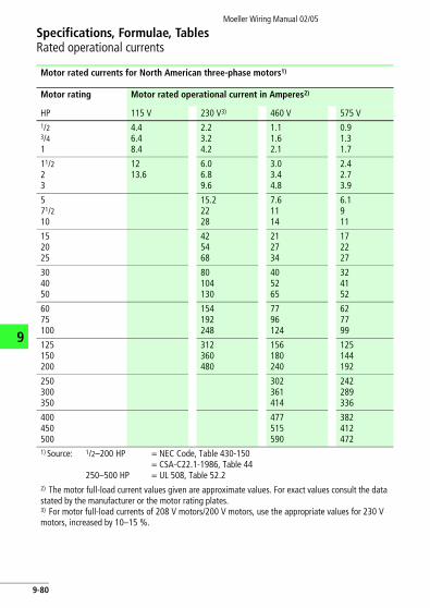
Specifications, Formulae, TablesRated operational currents
Moeller Wiring Manual 02/05
9
Motor rated currents for North American three-phase motors1)
Motor rating Motor rated operational current in Amperes2)
HP 115 V 230 V3) 460 V 575 V1/23/41
4.46.48.4
2.23.24.2
1.11.62.1
0.91.31.7
11/223
1213.6
6.06.89.6
3.03.44.8
2.42.73.9
571/210
15.22228
7.61114
6.1911
152025
425468
212734
172227
304050
80104130
405265
324152
6075100
154192248
7796124
627799
125150200
312360480
156180240
125144192
250300350
302361414
242289336
400450500
477515590
382412472
1) Source: 1/2–200 HP
250–500 HP
= NEC Code, Table 430-150= CSA-C22.1-1986, Table 44= UL 508, Table 52.2
2) The motor full-load current values given are approximate values. For exact values consult the data stated by the manufacturer or the motor rating plates.3) For motor full-load currents of 208 V motors/200 V motors, use the appropriate values for 230 V motors, increased by 10–15 %.
9-80

Moeller Wiring Manual 02/05
Specifications, Formulae, TablesConductors
9
Wiring and cable entries with grommets
Cable entry into closed devices is considerably simplified and improved by using cable grommets.
Cable grommetsFor direct and quick cable entry into an enclosure and as a plug.
Membrane-grommit metric
Conductor entry
Hole diameter
Cable external diameter
Using cable NYM/NYY, 4 core
Cable grommit part no
mm mm mm2
• IP66, with integrated push-through membrane
• PE and ther-moplastic elastomer, halogen free
M16 16.5 1–9 H03VV-F3 x 0.75NYM 1 x 16/3 x 1.5
KT-M16
M20 20.5 1–13 H03VV-F3 x 0.75NYM 5 x 1.5/5 x 2.5
KT-M20
M25 25.5 1–18 H03VV-F3 x 0.75NYM 4x 10
KT-M25
M32 32.5 1–25 H03VV-F3 x 0.75NYM 4 x 16/5 x 10
KT-M32
9-81

Specifications, Formulae, TablesConductors
Moeller Wiring Manual 02/05
9
Wiring and cable entries with cable glands
Cable glands, metric to EN 50262with 9, 10, 12, 14 or 15 mm long thread.
Cable glands Conductor entry
Hole diameter
Cable external diameter
Using cable NYM/NYY, 4 core
Cable glandpart no
mm mm mm2
• with locknut and integrated strain relief
• IP68 up to 5 bar, polyamid, halogen free
M12 12.5 3–7 H03VV-F3 x 0.75NYM 1 x 2.5
V-M12
M16 16.5 4.5–10 H05VV-F3 x 1.5NYM 1 x 16/3 x 1.5
V-M16
M20 20.5 6–13 H05VV-F4 x 2.5/3 x 4NYM 5 x 1.5/5 x 2.5
V-M20
M25 25.5 9–17 H05VV-F5 x 2.5/5 x 4NYM 5 x 2.5/5 x 6
V-M25
M32 32.5 13–21 NYM 5 x 10 V-M32
M32 32.5 18–25 NYM 5 x 16 V-M32G1)
M40 40.5 16–28 NYM 5 x 16 V-M40
M50 50.5 21–35 NYM 4 x 35/5 x 25 V-M50
M63 63.5 34–48 NYM 4 x 35 V-M63
1) Does not correspond to EN 50262.
9-82

Specifications, Formulae, TablesConductors
Moeller Wiring Manual 02/05
9
External diameter of conductors and cables
NYM: sheathed conductor NYY: plastic-sheathed cable H05RR-F: light rubber-sheathed flexible cable (NLH + NSH)
NYCY: cable with concentric conductor and plastic sheathNYCWY: cable with concentric wave-form conductor and plastic sheath
Number of conductors
Approximate external diameter (average of various makes)NYM NYY H05 H07 NYCY
RR-F RN-F NYCWYCross-section mm mm mm mm mmmm2 max. max. max.2 x 1.5 10 11 9 10 122 x 2.5 11 13 13 11 143 x 1.5 10 12 10 10 133 x 2.5 11 13 11 12 143 x 4 13 17 – 14 153 x 6 15 18 – 16 163 x 10 18 20 – 23 183 x 16 20 22 – 25 224 x 1.5 11 13 9 11 134 x 2.5 12 14 11 13 154 x 4 14 16 – 15 164 x 6 16 17 – 17 184 x 10 18 19 – 23 214 x 16 22 23 – 27 244 x 25 27 27 – 32 304 x 35 30 28 – 36 314 x 50 – 30 – 42 344 x 70 – 34 – 47 384 x 95 – 39 – 53 434 x 120 – 42 – – 464 x 150 – 47 – – 524 x 185 – 55 – – 604 x 240 – 62 – – 705 x 1.5 11 14 12 14 155 x 2.5 13 15 14 17 175 x 4 15 17 – 19 185 x 6 17 19 – 21 205 x 10 20 21 – 26 –5 x 16 25 23 – 30 –8 x 1.5 – 15 – – –10 x 1.5 – 18 – – –16 x 1.5 – 20 – – –24 x 1.5 – 25 – – –
9-83

Specifications, Formulae, TablesConductors
Moeller Wiring Manual 02/05
9
Cables and wiring, type abbreviation
Examples for complete cable designation PVC-sheathed wire, 0.75 mm2flexible, H05V-K 0.75 black
Heavy rubber-sheathed cable, 3-core, 2.5 mm2 without green/yellow protective conductor A07RN-F3 x 2.5
Identification of specification
Harmonized specification HRecognized national type A
Rated voltage UO/U
300/300V 03300/500 V 05450/750 V 07
Insulating material
PVC VNatural- and/or synthetic rubber RSilicon rubber S
Sheathing material
PVC VNatural- and/or synthetic rubber RPolychloroprene rubber NFibre-glass braid JTextile braid T
Special construction feature
Flat, separable conductor HFlat, non-separable conductor H2
Type of cableSolid -UStranded -RFlexible with cables for fixed installation -KFlexible with flexible cables -FHighly flexible with flexible cables -HTinsel cord -Y
Number of cores ...
Protective conductor
Without protective conductors XWith protective conductors G
Rated conductor cross-section ...
9-84

NotesMoeller Wiring Manual 02/05
9
9-85
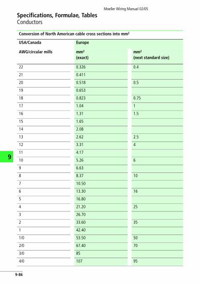
Specifications, Formulae, TablesConductors
Moeller Wiring Manual 02/05
9
Conversion of North American cable cross sections into mm2
USA/Canada Europe
AWG/circular mills mm2 (exact)
mm2 (next standard size)
22 0.326 0.4
21 0.411
20 0.518 0.5
19 0.653
18 0.823 0.75
17 1.04 1
16 1.31 1.5
15 1.65
14 2.08
13 2.62 2.5
12 3.31 4
11 4.17
10 5.26 6
9 6.63
8 8.37 10
7 10.50
6 13.30 16
5 16.80
4 21.20 25
3 26.70
2 33.60 35
1 42.40
1/0 53.50 50
2/0 67.40 70
3/0 85
4/0 107 95
9-86

Specifications, Formulae, TablesConductors
Moeller Wiring Manual 02/05
9
circular mills
250.000 127 120
300.000 152 150
350.000 177 185
400.000 203
450.000 228
500.000 253 240
550.000 279
600.000 304 300
650.000 329
700.000 355
750.000 380
800.000 405
850.000 431
12900.000 456
950.000 481
1.000.000 507 500
1.300.000 659 625
In addition to “circular mills”, cable sizes are often given in “MCM”: 250 000 circular mills = 250 MCM
USA/Canada Europe
AWG/circular mills mm2 (exact)
mm2 (next standard size)
9-87

Specifications, Formulae, TablesConductors
Moeller Wiring Manual 02/05
9
690/400
4 % 6 %
Short-circuit current
Rated cu
IK’’ In
A A A
1375 – 42
2750 1833 84
4400 2933 133
5500 3667 168
6875 4580 210
8660 5775 263
11000 7333 363
13750 9166 420
17320 11550 526
– 14666 672
– 18333 840
– 22916 1050
– 29333 1330
– 36666 1680
Rated currents and short-circuit currents for standard transformers
Rated voltage
400/230 V 525 V
Un
Short-circuit voltage UK
4 % 6 %
Rated capacity Rated current Short-circuit current
Rated current
In IK’’ In
kVA A A A A
50 72 1805 – 55
100 144 3610 2406 110
160 230 5776 3850 176
200 288 7220 4812 220
250 360 9025 6015 275
315 455 11375 7583 346
400 578 14450 9630 440
500 722 18050 12030 550
630 909 22750 15166 693
800 1156 – 19260 880
1000 1444 – 24060 1100
1250 1805 – 30080 1375
1600 2312 – 38530 1760
2000 2888 – 48120 2200
9-88

Specifications, Formulae, TablesConductors
Moeller Wiring Manual 02/05
525 V
6 %
rcuit Rated current
In
A A
– 55
2406 110
3850 176
4812 220
6015 275
7583 346
9630 440
12030 550
15166 693
19260 880
24060 1100
30080 1375
38530 1760
48120 2200
9
690/400 V
4 % 6 % 4 % 6 %
Short-circuit current
Rated current Short-circuit current
IK’’ In IK’’
A A A A A
1375 – 42 1042 –
2750 1833 84 2084 1392
4400 2933 133 3325 2230
5500 3667 168 4168 2784
6875 4580 210 5220 3560
8660 5775 263 6650 4380
11000 7333 363 8336 5568
13750 9166 420 10440 7120
17320 11550 526 13300 8760
– 14666 672 – 11136
– 18333 840 – 13920
– 22916 1050 – 17480
– 29333 1330 – 22300
– 36666 1680 – 27840
9-89

Moeller Wiring Manual 02/05
9
Specifications, Formulae, TablesFormulea
Ohm's Law
Resistance of a piece of wire
Copper:
l = Length of conductor [m] Aluminium:
z = Conductivity [m/Omm2] Iron:
A = Conductor cross section [mm2] Zinc:
Resistances
Transformer
Capacitors
Impedance
L = Inductance [H] f = Frequency [Hz]
C = Capacitance [F] v = Phase angle
XL = Inductive impedance [O]
XC = Capacitive impedance [O]
Parallel connection of resistances
With 2 parallel resistances: With 3 parallel resistances:
General calculation of resistances:
U I R V[ ]×= I UR--- A[ ]= R U
I--- Ω[ ]=
R lχ A×------------ Ω[ ]= χ 57 m
Ωmm2---------------=
χ 33 m
Ωmm2---------------=
χ 8.3 m
Ωmm2---------------=
χ 15.5 m
Ωmm2---------------=
XL 2 π f L Ω[ ]×××=
XC1
2 π f C×××----------------------------- Ω[ ]=
Z R2 XL XC�( )2+= Z Rcosϕ----------- Ω[ ]=
RgR1 R2×R1 R2+---------------- Ω[ ]= Rg
R1 R2× R3×R1 R2 R2 R3 R1 R3×+×+×--------------------------------------------------------------- Ω[ ]=
1R--- 1
R1----- 1
R2----- 1
R3----- ... 1 Ω⁄[ ]+ + += 1
Z-- 1
Z1---- 1
Z2---- 1
Z3---- ... 1 Ω⁄[ ]+ + +=
1X--- 1
X1----- 1
X2----- 1
X3----- ... 1 Ω⁄[ ]+ + +=
9-90

Specifications, Formulae, TablesFormulea
Moeller Wiring Manual 02/05
9
Electric power
Mechanical force between 2 parallel conductors
Mechanical force between 3 parallel conductors
Power Current consumption
DC
Single-phase AC
Three-phase AC
2 conductors with currents I1 and I2
s = Support spacing clearance [cm]
a = Support spacing clearance [cm]
3 conductors with current I
P U I× W[ ]= I PU--- A[ ]=
P U I cosϕ×× W[ ]= I PU cosϕ×--------------------- A[ ]=
P 3 U I cosϕ××× W[ ]= I P3 U cosϕ××---------------------------------- A[ ]=
F20.2 I1 I2 s×××
a----------------------------------- N[ ]= I1
I2
s
a
F3 0.808 F2 N[ ]×=
F3 0.865 F2 N[ ]×=
F3 0.865 F2 N[ ]×=
9-91

Specifications, Formulae, TablesFormulea
Moeller Wiring Manual 02/05
9
Voltage drop
Calculation of cross-section from voltage drop
Known power Known current
DC
Single-phase AC
Three-phase AC
DC Single-phase AC Three-phase AC
Known power
Known current
Power loss
DC Single-phase AC
Three-phase AC
l = Single length of conductor [m];A = Conductor cross section [mm2];z = Conductivity (copper: z = 57; aluminium: z = 33; iron: z = 8.3 )
UΔ 2 l× P×z A× U×---------------------- V[ ]= UΔ 2 l× l×
z A×------------------ V[ ]=
UΔ 2 l× P×z A× U×---------------------- V[ ]= UΔ 2 l× l×
z A×------------------ cos× ϕ V[ ]=
UΔ l P×z A× U×---------------------- V[ ]= UΔ 3 l l×
z A×------------ cos× ϕ V[ ]×=
A 2 l× P×z u× U×---------------------- mm2[ ]= A 2 l× P×
z u× U×---------------------- mm2[ ]= A l P×
z u× U×---------------------- mm2[ ]=
A 2 l× l×z u×------------------ mm2[ ]= A 2 l× l×
z u×------------------ cosϕ mm2[ ]×= A 3 l l×
z u×------------× cos× ϕ mm2[ ]=
PVerl2 l× P× P×z A× U× U×-------------------------------- W[ ]= PVerl
2 l× P× P×z A× U× U× cosϕ× cosϕ×------------------------------------------------------------------- W[ ]=
PVerll P× P×
z A× U× U× cosϕ× cosϕ×------------------------------------------------------------------- W[ ]=
mΩmm2---------------
9-92

Specifications, Formulae, TablesFormulea
Moeller Wiring Manual 02/05
9
Power of electric motors
Output Current consumption
DC
Single-phase AC
Three-phase AC
P1 = Rated mechanical power at the motor shaft P2 = Electrical power consumption
Efficiency
No. of poles Synchronous speed Full-load speed
2 3000 2800–2950
4 1500 1400–1470
6 1000 900–985
8 750 690–735
10 600 550–585
Synchronous speed = approx. no-load speed
P1 U l× h× W[ ]=l
P1
U h×------------- A[ ]=
P1 U l× cosϕ× h× W[ ]=l
P1
U cosϕ× h×------------------------------- A[ ]=
P1 (1.73) U× l× cosϕ× h× W[ ]=l
P1
(1.73) U× cosϕ× h×-------------------------------------------------- A[ ]=
h
P1
P2----- (100 %)×= P2
P1
h
----- W[ ]=
9-93

Moeller Wiring Manual 02/05
9
Specifications, Formulae, TablesInternational Unit System
International Unit System (SI)
Factors for conversion of old units into SI units
Basic parameters Physical parameters
Symbol SI basic unit Further related SI units
Length l m (Metre) km, dm, cm, mm, mm, nm, pm
Mass m kg (Kilogram) Mg, g, mg, mg
Time t s (Second) ks, ms, ms, ns
Electrical current I A (Ampere) kA, mA, mA, nA, pA
Thermo-dynamic temperature
T K (Kelvin) –
Amount of substance
n mole (Mol) Gmol, Mmol, kmol, mmol, mmol
Luminous intensity Iv cd (Candela) Mcd, kcd, mcd
Conversion factors
Parameter Old unit SI unit exact Approximate
Force 1 kp1 dyn
9.80665 N1·10-5 N
10 N1·10-5 N
Momentum of force
1 mkp 9.80665 Nm 10 Nm
Pressure 1 at1 Atm = 760 Torr1 Torr1 mWS1 mmWS1 mmWS
0.980665 bar1.01325 bar1.3332 mbar0.0980665 bar0.0980665 mbar9.80665 Pa
1 bar1.01 bar1.33 bar0.1 bar0.1 mbar10 Pa
Tension
Energy 1 mkp1 kcal1 erg
9.80665 J4.1868 kJ1·10-7 J
10 J4.2 kJ1·10-7 J
1 kp
mm2---------- 9.80665 N
mm2---------- 10 N
mm2----------
9-94

Specifications, Formulae, TablesInternational Unit System
Moeller Wiring Manual 02/05
9
Power
1.163 W 1.16 W
1 PS 0.73549 kW 0.740 kW
Heat transfer coefficient
dynamic viscosity
1 Poise
1 Poise 0.1
Kinetic viscosity 1 Stokes
Angle (flat) 1
1 gon
1
1 gon
57.296 1 rad
63.662 gon 1 rad
Conversion factors
Parameter Old unit SI unit exact Approximate
1kcalh-------- 4.1868kJ
h---- 4.2kJ
h----
1kcalh--------
1 kcal
m2h°C--------------- 4.1868 kJ
m2hK------------ 4.2 kJ
m2hK------------
1 kcal
m2h°C--------------- 1.163 W
m2K--------- 1.16 W
m2K---------
1 10 6� kps
m2--------⋅ 0 980665, 10 5� Ns
m2------⋅ 1 10 5� Ns
m2------⋅
0.1 Ns
m2------ 0.1 Ns
m2------
Pa s⋅
1 10 4� m2
s------⋅ 1 10 4� m2
s------⋅
1360--------pla 2 78, 10 3� pla⋅
1400--------pla 2 5 10 3� pla⋅,
π180-------- rad 17 5 10 3� rad⋅,
π200-------- rad 15 7, 10 3� pla⋅
9-95

Specifications, Formulae, TablesInternational Unit System
Moeller Wiring Manual 02/05
9
Conversion of SI units, coherences
Conversion of SI units and coherences
Parameter SI units name
Symbol Basic unit Conversion of SI units
Force Newton N
Force momentum
Newton-metre
Nm
Pressure Bar bar
Pascal Pa
Energy, heat Joule J 1 J = 1 Ws = 1 Nm
Power Watt W
Tension
Angle (flat) GradGon
1gon
360° = 1 pla = 2p rad 400 gon = 360°
Radian rad
Full circle pla 1 pla = 2p rad = 360°Voltage Volt V
Resistor Ohm O
Conductivity Siemens S
Electric charge
Coulomb C 1 · A · s
1 kg m⋅
s2--------------⋅
1 kg m2⋅
s2----------------⋅
105 kg
m s2⋅------------- 1 bar 105Pa 105 N
m2------= =
1 kg
m s2⋅-------------⋅ 1 Pa 10 5� bar=
1 kg m2⋅
s2----------------⋅
1 kg m2⋅
s3----------------⋅ W 1= J
s-- 1N m⋅
s------------=
N
mm2---------- 106 kg
m s2⋅------------- 1 N
mm2---------- 102 N
cm2--------=
1mm----
1 kg m2⋅
s3 A⋅----------------⋅ 1 V 1= W
A----⋅
1 kg m2⋅
s3 A2⋅----------------⋅ 1 Ω 1= V
A--- 1 W
A2-----⋅=⋅
1 s3 A2⋅
kg m2⋅----------------⋅ 1 M 1= A
V--- 1= A2
W-----⋅ ⋅
9-96

Specifications, Formulae, TablesInternational Unit System
Moeller Wiring Manual 02/05
9
Decimal powers (parts and multiples of units)
Capacitance Farad F
Field strength
Flux Weber Wb
Flux density Tesla T
Inductance Henry H
Power Prefix Symbol Power Prefix Symbol
10–18 Atto a 10–1 Deci d
10–15 Femto f 10 Deca da
10–12 Pico p 102 Hecto h
10–9 Nano n 103 Kilo k
10–6 Micro m 106 Mega M
10–3 Milli m 109 Giga G
10–2 Centi c 1012 Tera T
Conversion of SI units and coherences
Parameter SI units name
Symbol Basic unit Conversion of SI units
1 s4 A⋅
kg m2⋅----------------⋅ 1 F 1= C
V---⋅ 1 s A2⋅
W------------⋅=
Vm---- 1 kg m⋅
s3 A⋅--------------⋅ 1 V
m---- 1 W
A m⋅------------⋅=
1 kg m2⋅
s2 A⋅----------------⋅ 1 Wb 1= V s 1 W s⋅
A-----------⋅=⋅ ⋅
1 kg
s2 A⋅------------⋅ 1 T
Wb
m2------ 1 V s⋅
m2---------⋅ 1 W s⋅
m2A-----------⋅= = =
1 kg m2⋅
s2 A2⋅----------------⋅ 1 H
Wb
A------ 1 V s⋅
A---------⋅ 1 W s⋅
A2-----------⋅= = =
9-97

Specifications, Formulae, TablesInternational Unit System
Moeller Wiring Manual 02/05
9
Physical units
Mechanical force
Pressure
Obsolete units
SI unit: N (Newton) J/m (Joule/m)
Previous unit: kp (kilopond) dyn (Dyn)
1 N = 1 J/m = 1 kg m/s2 = 0.102 kp = 105 dyn
1 J/m = 1 N = 1 kg m/s2 = 0.102 kp = 105 dyn
1 kg m/s2 = 1 N = 1 J/m = 0.102 kp = 105 dyn
1 kp = 9.81 N = 9.81 J/m = 9.81 kg m/s2 = 0.981 106 dyn
1 dyn = 10–5 N = 10–5 J/m = 10–5 kg m/s2 = 1.02 10–5 kp
SI unit: Pa (Pascal) bar (Bar)
Previous unit:
at = kp/cm2 = 10 m WsTorr = mm Hgatm
1 Pa = 1 N/m2 = 10–5 bar
1 Pa = 10–5 bar = 10.2 · 10–6 at = 9.87 · 10–6 at = 7.5 · 10–3 Torr
1 bar = 105 Pa = 1.02 at = 0.987 at = 750 Torr
1 at = 98.1 · 103 Pa = 0.981 bar = 0.968 at = 736 Torr
1 atm = 101.3 · 103 Pa = 1.013 bar = 1.033 at = 760 Torr
1 Torr = 133.3 Pa = 1.333 · 10–3 bar = 1.359 · 10–3 at = 1.316 · 10–3 atm
9-98

Specifications, Formulae, TablesInternational Unit System
Moeller Wiring Manual 02/05
9
Work
Power
SI unit: J (Joule) Nm (Newtonmeter)
SI unit:(as before)
Ws (Wattsecond) kWh (Kilowatthour)
Previous unit: kcal (Kilocalorie) = cal · 10–3
1 Ws = 1 J = 1 Nm 107 erg
1 Ws = 278 · 10–9 kWh = 1 Nm = 1 J = 0.102 kpm = 0.239 cal
1 kWh = 3.6 · 106 Ws = 3.6 · 106 Nm = 3.6 · 106 J = 367 · 106 kpm = 860 kcal
1 Nm = 1 Ws = 278 · 10–9 kWh = 1 J = 0.102 kpm = 0.239 cal
1 J = 1 Ws = 278 · 10–9 kWh = 1 Nm = 0.102 kpm = 0.239 cal
1 kpm = 9.81 Ws = 272 · 10–6 kWh = 9.81 Nm = 9.81 J = 2.34 cal
1 kcal = 4.19 · 103 Ws = 1.16 · 10–3 kWh = 4.19 · 103 Nm = 4.19 · 103 J = 427 kpm
SI unit: Nm/s (Newtonmetre/s)J/s (Joule/s)
SI unit:(as before)
W (Watt)kW (Kilowatt)
Previous unit: kcal/s (Kilocalorie/sec.) = cal/s · 103
kcal/h (Kilocalorie/hour.) = cal/h · 106
kpm/s (Kilopondmetre/Sec.)
PS (metric horsepower)
1 W = 1 J/s = 1 Nm/s
1 W = 10–3 kW = 0.102 kpm/s = 1.36 ·10–3 PS = 860 cal/h = 0.239 cal/s
1 kW = 103 W = 102 kpm/s = 1.36 PS = 860 ·103 cal/h = 239 cal/s
1 kpm/s = 9.81 W = 9.81 · 10–3 kW = 13.3 ·10–3 PS = 8.43 ·103 cal/h = 2.34 cal/s
1 PS = 736 W = 0.736 kW = 75 kpm/s = 632 · 103 cal/h = 176 cal/s
1 kcal/h = 1.16 W = 1.16 · 10–3 kW = 119 · 10–3 kpm/s = 1.58 ·10–3 PS = 277.8 · 10–3 cal/s
1 cal/s = 4.19 W = 4.19 · 10–3 kW = 0.427 kpm/s = 5.69 · 10–3 PS = 3.6 kcal/h
9-99

Specifications, Formulae, TablesInternational Unit System
Moeller Wiring Manual 02/05
9
Magnetic field strength
Magnetic field strength
Magnetic flux density
SI unit:
Previous unit: Oe = (Oerstedt)
= 0.01256 Oe
= 12.56 Oe
1 Oe
Am---- Ampere
Metre -----------------
1 Am---- 0= 001 kA
m-----,
1 kAm----- 1000= A
m----
79= 6 Am----, 0= 0796 kA
m-----,
SI unit Wb (Weber)mWb (Microweber)
Previous unit: M = Maxwell
1 Wb = 1 Tm2
1 Wb = 106 mWb = 108 M
1 mWb = 10–6 Wb = 100 M
1 M = 10–8 Wb = 0.01 mWb
SI unit: T (Tesla)mT (Millitesla)
Previous unit: G = Gauss
1 T = 1 Wb/m2
1 T = 103 mT = 104 G
1 mT = 10–3 T = 10 G
1 G = 0.1–3 T = 0.1 mT
9-100

Specifications, Formulae, TablesInternational Unit System
Moeller Wiring Manual 02/05
9
Conversion of Imperial/American units into SI units
Length 1 in 1 ft 1 yd 1 mileLand mile
1 mileSea mile
m 25.4 · 10 –3 0.3048 0.9144 1.609 ·103 1.852 · 103
Weight 1 lb 1 ton (UK)long ton
1 cwt (UK) long cwt
1 ton (US)short ton
1 ounce 1 grain
kg 0.4536 1016 50.80 907.2 28.35 ·10–3 64.80 ·10–6
Area 1 sq.in 1 sq.ft 1 sq.yd 1 acre 1 sq.mile
m2 0.6452 · 10–3 92.90 · 10–3 0.8361 4.047 · 103 2.590 · 103
Volume 1 cu.in 1 cu.ft 1 cu.yd 1 gal (US) 1 gal (UK)
m3 16.39 · 10–6 28.32 · 10–3 0.7646 3.785 · 10–3 4.546 · 10–3
Force 1 lb 1 ton (UK)long ton
1 ton (US)short ton
1 pdl(poundal)
N 4.448 9.964 ·103 8.897 ·103 0.1383
Speed 1 Knot
0.4470 0.5144 0.3048 5.080 ·10–3
Pressure 1 in Hg 1 ft H2O 1 in H2O
bar 65.95 · 10-3 33.86 · 10-3 29.89 · 10-3 2.491 · 10-3
Energy, Work
1 HPh 1 BTU 1 PCU
J 2.684 ·106 1.055 ·103 1.90·103
1mileh ---------- 1
fts--- 1
ftmin---------
ms----
1 lbsq.in----------- 1 psi
9-101

Specifications, Formulae, TablesInternational Unit System
Moeller Wiring Manual 02/05
9
Conversion of Imperial/American units into SI units
Length 1 cm 1 m 1 m 1 km 1 km
0.3937 in 3.2808 ft 1.0936 yd 0.6214 mile Surface mile
0.5399 mile Nautical mile
Weight 1 g 1 kg 1 kg 1 t 1 t
15.43 grain 35.27 ounce 2.2046 lb. 0.9842 long ton
1.1023 short ton
Area 1cm2 1 m2 1 m2 1 m2 1 km2
0.1550 sq.in 10.7639 sq.ft 1.1960 sq.yd 0.2471 · 10–3 acre
0.3861 sq.mile
Volume 1cm3 1 l 1 m3 1 m3 1 m3
0.06102 cu.in 0.03531 cu.ft 1.308 cu.yd 264.2 gal (US) 219.97 gal (UK)
Force 1 N 1 N 1 N 1 N
0.2248 lb 0.1003 · 10–3 long ton (UK)
0.1123 · 10–3 short ton (US)
7.2306 pdl (poundal)
Speed 1 m/s 1 m/s 1 m/s 1 m/s
3.2808 ft/s 196.08 ft/min 1.944 knots 2.237 mph
Pressure 1 bar 1 bar 1 bar 1 bar
14.50 psi 29.53 in Hg 33.45 ft H2O 401.44 in H2O
Energy, Work
1 J 1 J 1 J
0.3725 · 10–6 HPh 0.9478 · 10–3 BTU 0.5263 · 10–3 PCU
9-102

NotesMoeller Wiring Manual 02/05
9-103
9

NotesMoeller Wiring Manual 02/05
9-104
9