Embed Size (px)
Citation preview

8/12/2015
1
www.eit.edu.au
Cavitation in High Energy
Pumps – Detection and Assessment of Damage
PotentialSteve Mackay – Dean of
Engineering
www.eit.edu.au
EIT Micro-Course Series
• Every two weeks we present a 35 to 45 minute interactive course
• Practical, useful with Q & A throughout
• Go to http://www.eit.edu.au/free-courses
• You get the recording and slides

8/12/2015
2
www.eit.edu.au
Topics
• Overview
• Cavitation
• NPSH
• Factors Causing Cavitation
• Supplementary Pictures
www.eit.edu.au
Cavitation in High Energy Pumps
Detection and Assessment of
Damage Potential

8/12/2015
3
www.eit.edu.au
Prepared and Presented by
Paresh Girdhar
and
Steve Mackay
www.eit.edu.au
Overview of Topic
Cavitation related erosion damage continues to be a problem in a variety of centrifugal pumps. The methods of
detection and assessment of the damage potential are examined in thispractical discussion.
8/12/2015
4
www.eit.edu.au
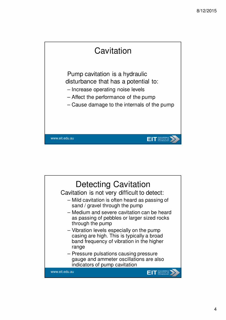
Cavitation
Pump cavitation is a hydraulic
disturbance that has a potential to:
– Increase operating noise levels
– Affect the performance of the pump
– Cause damage to the internals of the pump
www.eit.edu.au
Detecting CavitationCavitation is not very difficult to detect:
– Mild cavitation is often heard as passing of sand / gravel through the pump
– Medium and severe cavitation can be heard as passing of pebbles or larger sized rocks through the pump
– Vibration levels especially on the pump casing are high. This is typically a broad band frequency of vibration in the higher range
– Pressure pulsations causing pressure gauge and ammeter oscillations are also indicators of pump cavitation
8/12/2015
5
www.eit.edu.au
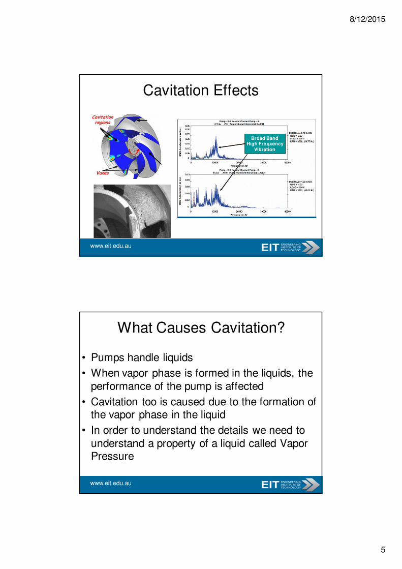
Cavitation Effects
Broad BandHigh Frequency
Vibration
www.eit.edu.au
What Causes Cavitation?
• Pumps handle liquids
• When vapor phase is formed in the liquids, the
performance of the pump is affected
• Cavitation too is caused due to the formation of the vapor phase in the liquid
• In order to understand the details we need to
understand a property of a liquid called Vapor Pressure

8/12/2015
6
www.eit.edu.au
Vapour Pressure• If a quantity of liquid is placed in an
evacuated, closed container
• After some period of time, a vapour phase forms in the space above the liquid surface.
• This space consists of molecules that have passed through the liquid surface from liquid to gas.
• The pressure exerted by that vapour phase is called the vapour (or saturation) pressure.
• For a pure liquid, this pressure depends only on the temperature.
www.eit.edu.au
Examples of Vapor Pressure• Vapor pressure is 101 kPa (1 atmosphere) at
– 100°C for water
– 78.5°C for ethyl alcohol
– 125.7°C for octane.
• Similarly, at 20°C
– Water has a vapor pressure of 2.33 kPa
– Isopropyl alcohol (rubbing alcohol) has a vapor pressure of
4.4 kPa (33 mm Hg)
• Alcohol has a higher vapor pressure than water at
the same temperature.
• Alcohol has a tendency to evaporate more easily (cf
water).

8/12/2015
7
www.eit.edu.au
Cavitation
• Very often pumps handle liquids with suction conditions very close to a liquid’s vapor pressure.
• When a liquid is drawn into the pump inlet there is a pressure drop resulting from the fluid friction along the pipeline, valves, fitting and flow pattern.
www.eit.edu.au
Cavitation
• Under conditions, when
the reduced pressure
approaches the vapor
pressure of the liquid (at
that temperature) it causes the liquid to
vaporize
• As these vapor bubbles
travel further into the impeller, the pressure
rises again causing the
bubbles to collapse or
implode.
BubbleImplosion

8/12/2015
8
www.eit.edu.au
Implosion of Bubbles• These bubbles collapse rapidly and
violently when the local absolute pressure increases
• On implosion, micro jets of liquid rush in with high velocity to fill the imploded
space and impinge with energy on the metal
• These implosions cause severe damage to pump internals and
can adversely affect pump performance
• This phenomenon is called as cavitation
MicroJets
Erosion
www.eit.edu.au
Cavitation• Cavitation damage to a centrifugal pump may range
from minor pitting to catastrophic failure and
depends on the pumped fluid characteristics, energy
levels and duration of cavitation
• Most of the damage usually occurs within the
impeller; specifically, on the leading face of the non-
pressure side of the vanes.
• The net effect observed on the impeller vane will be
a pockmarked, rough surface.

8/12/2015
9
www.eit.edu.au
Cavitation Effects
www.eit.edu.au
NPSH
• Thus, the pressure of
the liquid as it enters the impeller eye has to
be greater than the
vaporization pressure.
• This excess head of
liquid column is called the NPSH or net
positive suction head.
8/12/2015
10
www.eit.edu.au
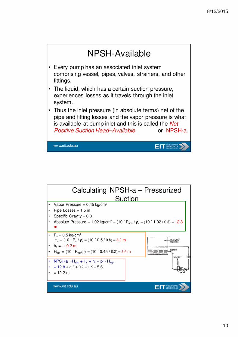
NPSH-Available
• Every pump has an associated inlet system
comprising vessel, pipes, valves, strainers, and other fittings.
• The liquid, which has a certain suction pressure, experiences losses as it travels through the inlet
system.
• Thus the inlet pressure (in absolute terms) net of the
pipe and fitting losses and the vapor pressure is what is available at pump inlet and this is called the Net
Positive Suction Head–Available or NPSH-a.
www.eit.edu.au
Calculating NPSH-a – Pressurized Suction
• Vapor Pressure = 0.45 kg/cm2
• Pipe Losses = 1.5 m
• Specific Gravity = 0.8
• Absolute Pressure = 1.02 kg/cm2 = (10 ´ Pabs / ρ) = (10 ´ 1.02 / 0.8) = 12.8
m
• Ps = 0.5 kg/cm2
Hs = (10 ´ Ps / ρ) = (10 ´ 0.5 / 0.8) = 6.3 m
• hs = + 0.2 m
• Hvap = (10 ´ Pvap/ρ) = (10 ´ 0.45 / 0.8) = 5.6 m
• NPSH-a =Habs + Hs + hs – pl - Hvap
• = 12.8 + 6.3 + 0.2 − 1.5 − 5.6
• = 12.2 m
8/12/2015
11
www.eit.edu.au
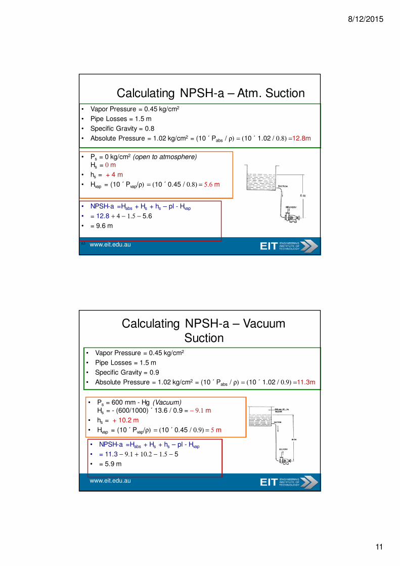
Calculating NPSH-a – Atm. Suction• Vapor Pressure = 0.45 kg/cm2
• Pipe Losses = 1.5 m
• Specific Gravity = 0.8
• Absolute Pressure = 1.02 kg/cm2 = (10 ´ Pabs / ρ) = (10 ´ 1.02 / 0.8) =12.8m
• Ps = 0 kg/cm2 (open to atmosphere)
Hs = 0 m
• hs = + 4 m
• Hvap = (10 ´ Pvap/ρ) = (10 ´ 0.45 / 0.8) = 5.6 m
• NPSH-a =Habs + Hs + hs – pl - Hvap
• = 12.8 + 4 − 1.5 − 5.6
• = 9.6 m
63
www.eit.edu.au
Calculating NPSH-a – Vacuum Suction
• Vapor Pressure = 0.45 kg/cm2
• Pipe Losses = 1.5 m
• Specific Gravity = 0.9
• Absolute Pressure = 1.02 kg/cm2 = (10 ´ Pabs / ρ) = (10 ´ 1.02 / 0.9) =11.3m
• Ps = 600 mm - Hg (Vacuum)
Hs = - (600/1000) ´ 13.6 / 0.9 = − 9.1 m
• hs = + 10.2 m
• Hvap = (10 ´ Pvap/ρ) = (10 ´ 0.45 / 0.9) = 5 m
• NPSH-a =Habs + Hs + hs – pl - Hvap
• = 11.3 − 9.1 + 10.2 − 1.5 − 5
• = 5.9 m

8/12/2015
12
www.eit.edu.au
Calculating NPSH-a – Negative Lift• Vapor Pressure = 0.45 kg/cm2
• Pipe Losses = 1.5 m
• Specific Gravity = 0.8
• Absolute Pressure = 1.02 kg/cm2 = (10 ´ Pabs / ρ) = (10 ´ 1.02 / 0.8)=
12.8m
• Ps = 0 kg/cm2 (open to atmosphere)
Hs = 0 m
• hs = − 3 m
• Hvap = (10 ´ Pvap/ρ) = (10 ´ 0.45 / 0.8) =
5.7 m
• NPSH-a =Habs + Hs + hs – pl -
Hvap
• = 12.8 + 0 − 3 − 1.5 − 5.7
• = 2.6 m
www.eit.edu.au
NPSH-Required• As the liquid in the suction pipe approaches the impeller eye,
losses in terms of liquid head occur due to:
– Velocity and Acceleration of liquid
– Sharp change in direction to enter the impeller
– Higher flow rates
– Recirculation due to higher clearance at wear rings
– Use of smaller diameter impellers in volutes
• The pump inlet nozzle and impeller inlet vane geometry are designed to minimize the losses but cannot be eliminated entirely.
• The summation of the above losses is termed the Net Positive Suction Head as required by the pump or NPSH-r.

8/12/2015
13
www.eit.edu.au
NPSH-Required• The Hydraulic Institute defines NPSH-r of a
pump as the NPSH that causes the total head (first stage head of multistage
pumps) to be reduced by 3%, due to flow blockage from cavitation vapour in the impeller vanes
• NPSH-r by the above definition does not necessarily imply that this is the point at
which cavitation starts; that level is referred to as incipient cavitation.
• The NPSH at incipient cavitation can be from 2 to 20 times the 3% NPSH-r value,
depending on pump design especially in case of high suction energy pumps.
www.eit.edu.au
Q vs. NPSH-r Curve
• NPSH-r or Net Positive Suction Head – required
by the pump is the minimum pressure or head
required at the pump inlet to avoid a damaging
phenomenon called cavitation.
• NPSH-r on the characteristic curves is the
measured suction head obtained while throttling
the suction flow until a 3% drop in the differential
head is observed at any particular flow rate
• NPSH-r is dependent on the service liquid but it is
known that cavitation resulting from cold water is
most damaging as compared with most commonly
pumped liquids hence no corrections are made while using it for other liquids
8/12/2015
14
www.eit.edu.au
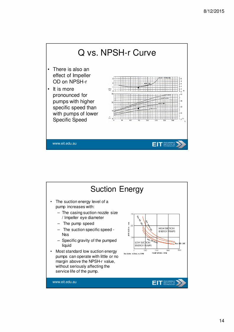
• There is also an effect of Impeller
OD on NPSH-r
• It is more pronounced for
pumps with higher specific speed than with pumps of lower Specific Speed
Q vs. NPSH-r Curve
www.eit.edu.au
Suction Energy
• The suction energy level of a
pump increases with:
– The casing suction nozzle size / Impeller eye diameter
– The pump speed
– The suction specific speed -Nss
– Specific gravity of the pumped liquid
• Most standard low suction energy
pumps can operate with little or no margin above the NPSH-r value, without seriously affecting the service life of the pump.

8/12/2015
15
www.eit.edu.au
Inception of Cavitation
• Thus we see that the NPSH-r as defined by the Hydraulic Institute is not a true indicator of
incipient cavitation, though it a practical method
• This necessitates a theoretical evaluation of NPSH-r
• The theoretical derivation of NPSH-r or “Cavitation Free NPSH” is based on factors such as:
– Head loss due to friction
– Head drop due to fluid acceleration
– Head loss due to improper fluid entry into the
impeller blade
www.eit.edu.au
NPSH Margin
• As there is ambiguity with regards to the
inception of cavitation, a margin is kept between the NPSH-available and NPSH-required
• Most pump specifications quote a margin
of not less than 1 to 1.5 m over the entire range of pump operation
• Another approach adopted to define the
margin is by taking the ratio of NPSH-a and NPSH-r.

8/12/2015
16
www.eit.edu.au
NPSH RatioMinimum NPSH Margin Ratio Guidelines (NPSH-a / NPSH-r)
Suction Energy Levels
Application Low Medium High
Petroleum 1.1-a 1.3-c
Chemical 1.1-a 1.3-c
Electrical Power 1.1-a 1.5-c 2.0-c
Nuclear Power 1.5-b 2.0-c 2.5-c
Cooling Towers 1.3-b 1.5-c 2.0-c
Water / Waste Water 1.1-a 1.3-c 2.0-c
“a” – Or 0.6 m (2 feet) whichever is greater
“b” – Or 0.9 m (3 feet) whichever is greater
“c” – Or 1.5 m (5 feet) whichever is greater
www.eit.edu.au
High Energy Pump Cavitation• In high energy pumps, NPSH obtained by 3%
head drop is not sufficient
• This NPSH-r (3%) value could be 5 to 6 times
less than the suction head when bubble formation takes place and can cause impeller
blade erosion
• As in other pumps causes the following but
with greater consequences:
– Erosion of impellers at suction
– Introduces compressible volume in liquid that
causes pressure pulsations and affects
performance

8/12/2015
17
www.eit.edu.au
Factors Affecting Cavitation in High Energy Pumps
• The factors that intensify cavitation effects in
High Energy (HE) pumps are
– Liquid Properties (vapor pressure, specific gravity…)
– Hydraulic Design – Most important factor is Impeller tip speed (radius of impeller eye time
shaft angular speed), Blade angle, positive and negative pre-swirls
– Impeller Metallurgy
– Operating point and conditions (flow rate)
www.eit.edu.au
Assessment of Impeller Life • Research in this area has come up with a method to
assess the life of the impeller due to cavitation based
on many parameters indicated in earlier slide
• A simplistic equation estimating life of impeller is as follows
– ∆m = Loss of Material/ Erosion depth (penetration of 75% of vane thickness is considered as end of life)
– Uc – Impeller tip speed
– L – Cavity Length (see next slide)
– t - time of operation
– a, b - constantsThus by knowing thickness the time “t” can be
back-calculated
tLUmba
c××=∆

8/12/2015
18
www.eit.edu.au
Cavity Length – HE Pump Impeller
www.eit.edu.au
Cavitation Prevention
• Cavitation can be prevented by ensuring a proper margin or ratio of the NPSH-a to the NPSH-r
• However even after careful design and specification it is possible that due to equipment installation issues and revised operating conditions the situation may lead to cavitation
• Often poorly insulated lines result in affecting inlet temperature of the liquid leading to cavitation issues
8/12/2015
19
www.eit.edu.au
Cavitation Prevention• Solutions to improve NPSH margin
include– Lowering Inlet temperature
– Increasing suction vessel pressure or head
– Raising the level of the suction vessel
– Lowering the pump in a pit
– Replacing the pump type with a vertical submersible type
– Increasing suction line size
– Removal of redundant valves, fittings, strainers from inlet line
– Installing an inducer to the pump impeller
www.eit.edu.au
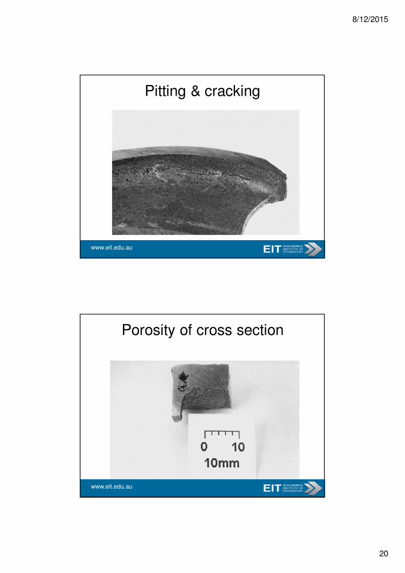
Supplementary Slides
Cavitation versus corrosion
Can you distinguish between them ?
8/12/2015
20
www.eit.edu.au
Pitting & cracking
www.eit.edu.au
Porosity of cross section

8/12/2015
21
www.eit.edu.au
Porosity in failed bronze one
www.eit.edu.au
Cavitation Failure
8/12/2015
22
www.eit.edu.au
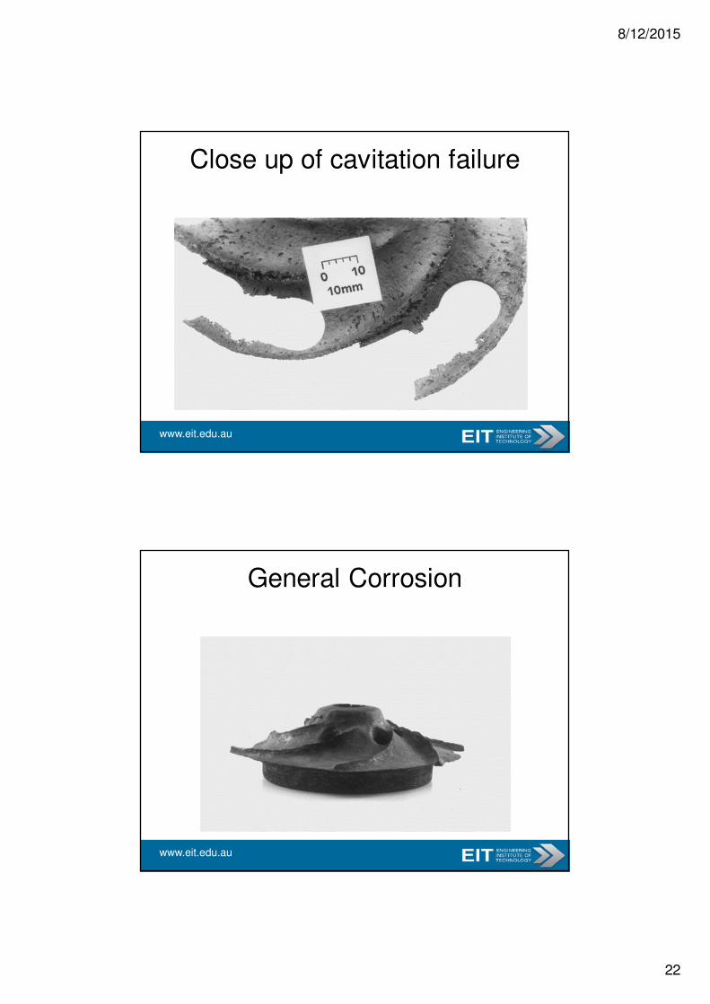
Close up of cavitation failure
www.eit.edu.au
General Corrosion

8/12/2015
23
www.eit.edu.au
Erosion-corrosion grooves
www.eit.edu.au


![Visualization of Unsteady Behavior of Cavitation in ... · cavitation state, transition-cavitation state, and super-cavitation state in the orifice throat [5]. Under relative high](https://img.dokumen.tips/doc/110x75/5b4f673e7f8b9a166e8c4c74/visualization-of-unsteady-behavior-of-cavitation-in-cavitation-state-transition-cavitation.jpg)