Embed Size (px)
Citation preview
UG181: EFR32 Flex Gecko 2400/915 MHzWireless Starter Kit
The SLWSTK6060A Wireless Starter Kit is an excellent startingpoint to get familiar with the EFR32™ Flex Gecko Wireless Sys-tem-on-Chip.The Wireless Starter Kit Mainboard contains sensors and peripherals demonstratingsome of the Flex Gecko's many capabilities. The kit provides all necessary tools for de-veloping a Silicon Labs wireless application.
KIT FEATURES
• Ethernet and USB connectivity• Advanced Energy Monitor• Packet Trace Interface support• SEGGER J-Link on-board debugger• Debug Multiplexer supporting external
hardware as well as radio board• Silicon Labs' Si7021 Relative Humidity and
Temperature sensor• Ultra low power 128x128 pixel Memory
LCD• User LEDs / Pushbuttons• 20-pin 2.54 mm header for expansion
boards• Breakout pads for direct access to all radio
I/O pins• Power sources includes USB, CR2032
coin cell and AA batteries.
RADIO BOARD FEATURES
• EFR32 Flex Gecko Wireless SoC with 256kB Flash and 32 kB RAM.(EFR32FG1P133F256GM48)
• Inverted-F PCB antenna (2.4 GHz band)• SMA connector (915 MHz band)
SOFTWARE SUPPORT
• Simplicity Studio™• Energy Profiler• Network Analyzer
silabs.com | Smart. Connected. Energy-friendly. Rev. 1.00
1. Introduction
The SLWSTK6060A Wireless Starter Kit provides a complete development platform for Silicon Labs EFR32 Flex Gecko Wireless Sys-tem-on-Chips.
The core of the SLWSTK6060A is the Wireless Starter Kit Mainboard which features an on-board J-Link debugger, an Advanced Ener-gy Monitor (AEM) for real-time current and voltage monitoring, a Virtual COM port interface (VCOM), and access to the Packet TraceInterface (PTI).
The WSTK Mainboard is paired with an EFR32FG 2400/915 MHz 19.5 dBm radio board that plugs directly into the mainboard. Theradio board features the EFR32 itself and the RF interface. Please refer to the Reference Manual for the included radio boards for de-tailed specifications and RF performance figures.
All debug functionality, including AEM, VCOM and PTI, can also be used towards an external target instead of the included radio board.
To further enhance the WSTK usability, the WSTK Mainboard contains sensors and peripherals demonstrating some of the WirelessSoC's many capabilities.
1.1 Kit Contents
The following items are included in the box:• 2x BRD4001A Wireless Starter Kit Mainboards• 2x BRD4250A EFR32FG 2400/915 MHz 19.5 dBm Radio Boards• 2x 915 MHz antennas with SMA connector• 2x CR2032 Lithium batteries• 2x AA battery holders• 2x USB Type A <-> USB Mini-B cables• 1x BRD8010A WSTK Debug Adapter
1.2 Getting Started
Detailed instructions for how to get started can be found on the Silicon Labs web pages:
http://www.silabs.com/start-efr32fg
UG181: EFR32 Flex Gecko 2400/915 MHz Wireless Starter KitIntroduction
silabs.com | Smart. Connected. Energy-friendly. Rev. 1.00 | 1
2. Kit Hardware Layout
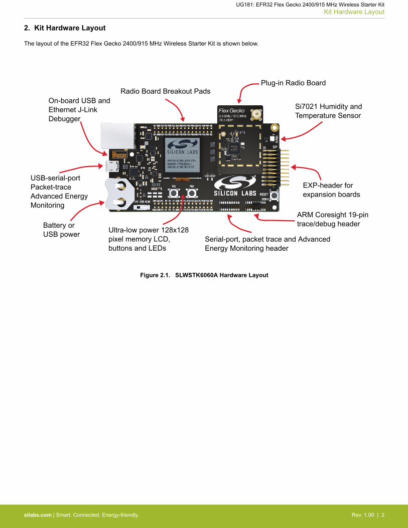
The layout of the EFR32 Flex Gecko 2400/915 MHz Wireless Starter Kit is shown below.
On-board USB andEthernet J-LinkDebugger
Radio Board Breakout PadsPlug-in Radio Board
Si7021 Humidity andTemperature Sensor
EXP-header forexpansion boards
Serial-port, packet trace and AdvancedEnergy Monitoring header
ARM Coresight 19-pintrace/debug header
Ultra-low power 128x128pixel memory LCD,buttons and LEDs
Battery orUSB power
USB-serial-portPacket-traceAdvanced EnergyMonitoring
Figure 2.1. SLWSTK6060A Hardware Layout
UG181: EFR32 Flex Gecko 2400/915 MHz Wireless Starter KitKit Hardware Layout
silabs.com | Smart. Connected. Energy-friendly. Rev. 1.00 | 2
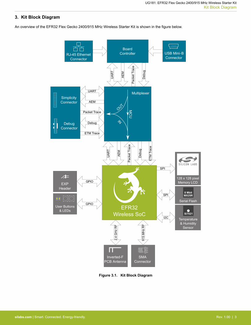
3. Kit Block Diagram
An overview of the EFR32 Flex Gecko 2400/915 MHz Wireless Starter Kit is shown in the figure below.
Deb
ug
USB Mini-BConnector
UA
RT
RJ-45 EthernetConnector
Pac
ket T
race
AE
M
Multiplexer
Debug
UART
ETM Trace
Packet Trace
AEM
Deb
ug
UA
RT
Pac
ket T
race
AE
M
SimplicityConnector
DebugConnector
BoardController
OUT
INM
CU
SMAConnector
915
MH
z R
F
2.4
GH
z R
F
Inverted-FPCB Antenna
EFR32 Wireless SoC
ETM
Tra
ce
128 x 128 pixelMemory LCD
I2CSi7021
Temperature& Humidity
Sensor
SPI8 MbitMX25R
Serial Flash
GPIOEXP
Header
User Buttons& LEDs
GPIO
Figure 3.1. Kit Block Diagram
UG181: EFR32 Flex Gecko 2400/915 MHz Wireless Starter KitKit Block Diagram
silabs.com | Smart. Connected. Energy-friendly. Rev. 1.00 | 3
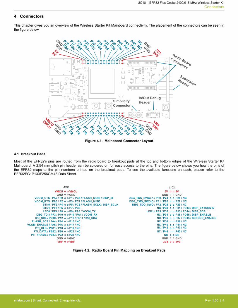
4. Connectors
This chapter gives you an overview of the Wireless Starter Kit Mainboard connectivity. The placement of the connectors can be seen inthe figure below.
SimplicityConnector
In/Out DebugHeader
GND GND5V5V
P25 P24
P27 P26
P29 P28
P31 P30
P33 P32
P35 P34
P37 P36
P39 P38
P41 P40
P43 P42
P45 P44GND GND
NC NC
Radio BoardConnectors
ExpansionHeader
GND GND
VMCUVMCU P1 P0
P3 P2
P5 P4
P7 P6
P9 P8
P11 P10
P13 P12
P15 P14
P17 P16
P19 P18
P21 P20
GND GND
P23 P22
VRF VRF
3V33V3
Figure 4.1. Mainboard Connector Layout
4.1 Breakout Pads
Most of the EFR32's pins are routed from the radio board to breakout pads at the top and bottom edges of the Wireless Starter KitMainboard. A 2.54 mm pitch pin header can be soldered on for easy access to the pins. The figure below shows you how the pins ofthe EFR32 maps to the pin numbers printed on the breakout pads. To see the available functions on each, please refer to theEFR32FG1P133F256GM48 Data Sheet.
GNDVMCU
P23 / NCP21 / NCP19 / NCP17 / NC
GND
P15 / NCP13 / PC11 / I2C_SDAP11 / PA1 / VCOM_RXP9 / PA0 / VCOM_TXP7 / PC9P5 / PC8 / FLASH_SCLK / DISP_SCLKP3 / PC7 / FLASH_MISOP1 / PC6 / FLASH_MOSI / DISP_SI
GNDGND5V5V
NCNCP45 / NCNC / P44P43 / NCNC / P42P41 / NCNC / P40
3V33V3
P39 / NCNC / P38P37 / PD15 / SENSOR_ENABLENC / P36P35 / PD15 / DISP_ENABLENC / P34P33 / PD14 / DISP_SCSLED1 / PF5 / P32P31 / PD13 / DISP_EXTCOMINNC / P30P29 / NCDBG_TDO_SWO / PF2 / P28P27 / NCDBG_TMS_SWDIO / PF1 / P26P25 / NCDBG_TCK_SWCLK / PF0 / P24
GNDGNDVRF
GNDVMCU
PTI_FRAME / PB13 / P22PTI_DATA / PB12 / P20
PTI_CLK / PB11 / P18VCOM_ENABLE / PA5 / P16
GND
FLASH_SCS / PA4 / P14I2C_SCL / PC10 / P12DBG_TDI / PF3 / P10
LED0 / PF4 / P8BTN1 / PF7 / P6BTN0 / PF6 / P4
VCOM_RTS / PA3 / P2VCOM_CTS / PA2 / P0
VRF
J101 J102
Figure 4.2. Radio Board Pin Mapping on Breakout Pads
UG181: EFR32 Flex Gecko 2400/915 MHz Wireless Starter KitConnectors
silabs.com | Smart. Connected. Energy-friendly. Rev. 1.00 | 4
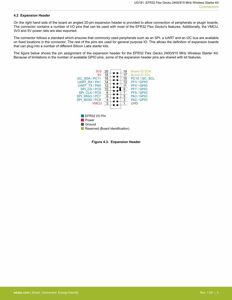
4.2 Expansion Header
On the right hand side of the board an angled 20-pin expansion header is provided to allow connection of peripherals or plugin boards.The connector contains a number of I/O pins that can be used with most of the EFR32 Flex Gecko's features. Additionally, the VMCU,3V3 and 5V power rails are also exported.
The connector follows a standard which ensures that commonly used peripherals such as an SPI, a UART and an I2C bus are availableon fixed locations in the connector. The rest of the pins are used for general purpose IO. This allows the definition of expansion boardsthat can plug into a number of different Silicon Labs starter kits.
The figure below shows the pin assignment of the expansion header for the EFR32 Flex Gecko 2400/915 MHz Wireless Starter Kit.Because of limitations in the number of available GPIO pins, some of the expansion header pins are shared with kit features.
124
86
10
35
97
12131411
15161718
20 19
VMCUSPI_MOSI / PC6SPI_MISO / PC7
SPI_CLK / PC8SPI_CS / PC9
UART_TX / PA0UART_RX / PA1I2C_SDA / PC11
5V3V3
GNDPA2 / GPIOPA3 / GPIOPF6 / GPIOPF7 / GPIOPF4 / GPIOPF3 / GPIOPC10 / I2C_SCL
Board ID SDABoard ID SCL
Reserved (Board Identification)
EFR32 I/O Pin
Figure 4.3. Expansion Header
UG181: EFR32 Flex Gecko 2400/915 MHz Wireless Starter KitConnectors
silabs.com | Smart. Connected. Energy-friendly. Rev. 1.00 | 5
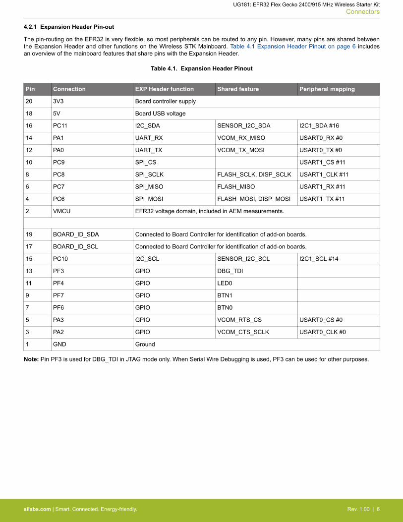
4.2.1 Expansion Header Pin-out
The pin-routing on the EFR32 is very flexible, so most peripherals can be routed to any pin. However, many pins are shared betweenthe Expansion Header and other functions on the Wireless STK Mainboard. Table 4.1 Expansion Header Pinout on page 6 includesan overview of the mainboard features that share pins with the Expansion Header.
Table 4.1. Expansion Header Pinout
Pin Connection EXP Header function Shared feature Peripheral mapping
20 3V3 Board controller supply
18 5V Board USB voltage
16 PC11 I2C_SDA SENSOR_I2C_SDA I2C1_SDA #16
14 PA1 UART_RX VCOM_RX_MISO USART0_RX #0
12 PA0 UART_TX VCOM_TX_MOSI USART0_TX #0
10 PC9 SPI_CS USART1_CS #11
8 PC8 SPI_SCLK FLASH_SCLK, DISP_SCLK USART1_CLK #11
6 PC7 SPI_MISO FLASH_MISO USART1_RX #11
4 PC6 SPI_MOSI FLASH_MOSI, DISP_MOSI USART1_TX #11
2 VMCU EFR32 voltage domain, included in AEM measurements.
19 BOARD_ID_SDA Connected to Board Controller for identification of add-on boards.
17 BOARD_ID_SCL Connected to Board Controller for identification of add-on boards.
15 PC10 I2C_SCL SENSOR_I2C_SCL I2C1_SCL #14
13 PF3 GPIO DBG_TDI
11 PF4 GPIO LED0
9 PF7 GPIO BTN1
7 PF6 GPIO BTN0
5 PA3 GPIO VCOM_RTS_CS USART0_CS #0
3 PA2 GPIO VCOM_CTS_SCLK USART0_CLK #0
1 GND Ground
Note: Pin PF3 is used for DBG_TDI in JTAG mode only. When Serial Wire Debugging is used, PF3 can be used for other purposes.
UG181: EFR32 Flex Gecko 2400/915 MHz Wireless Starter KitConnectors
silabs.com | Smart. Connected. Energy-friendly. Rev. 1.00 | 6
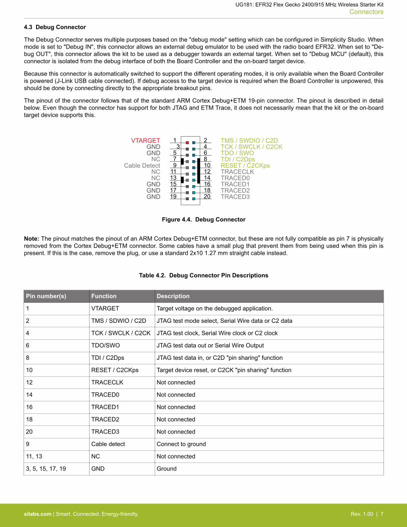
4.3 Debug Connector
The Debug Connector serves multiple purposes based on the "debug mode" setting which can be configured in Simplicity Studio. Whenmode is set to "Debug IN", this connector allows an external debug emulator to be used with the radio board EFR32. When set to "De-bug OUT", this connector allows the kit to be used as a debugger towards an external target. When set to "Debug MCU" (default), thisconnector is isolated from the debug interface of both the Board Controller and the on-board target device.
Because this connector is automatically switched to support the different operating modes, it is only available when the Board Controlleris powered (J-Link USB cable connected). If debug access to the target device is required when the Board Controller is unpowered, thisshould be done by connecting directly to the appropriate breakout pins.
The pinout of the connector follows that of the standard ARM Cortex Debug+ETM 19-pin connector. The pinout is described in detailbelow. Even though the connector has support for both JTAG and ETM Trace, it does not necessarily mean that the kit or the on-boardtarget device supports this.
1 24
86
10
35
912
13 1411
15 1617 18
2019
TMS / SWDIO / C2DTCK / SWCLK / C2CKTDO / SWOTDI / C2Dps
TRACECLKTRACED0TRACED1TRACED2TRACED3
RESET / C2CKps
GNDNC
NC
GND
GNDGND
7
GNDVTARGET
Cable Detect
NC
Figure 4.4. Debug Connector
Note: The pinout matches the pinout of an ARM Cortex Debug+ETM connector, but these are not fully compatible as pin 7 is physicallyremoved from the Cortex Debug+ETM connector. Some cables have a small plug that prevent them from being used when this pin ispresent. If this is the case, remove the plug, or use a standard 2x10 1.27 mm straight cable instead.
Table 4.2. Debug Connector Pin Descriptions
Pin number(s) Function Description
1 VTARGET Target voltage on the debugged application.
2 TMS / SDWIO / C2D JTAG test mode select, Serial Wire data or C2 data
4 TCK / SWCLK / C2CK JTAG test clock, Serial Wire clock or C2 clock
6 TDO/SWO JTAG test data out or Serial Wire Output
8 TDI / C2Dps JTAG test data in, or C2D "pin sharing" function
10 RESET / C2CKps Target device reset, or C2CK "pin sharing" function
12 TRACECLK Not connected
14 TRACED0 Not connected
16 TRACED1 Not connected
18 TRACED2 Not connected
20 TRACED3 Not connected
9 Cable detect Connect to ground
11, 13 NC Not connected
3, 5, 15, 17, 19 GND Ground
UG181: EFR32 Flex Gecko 2400/915 MHz Wireless Starter KitConnectors
silabs.com | Smart. Connected. Energy-friendly. Rev. 1.00 | 7
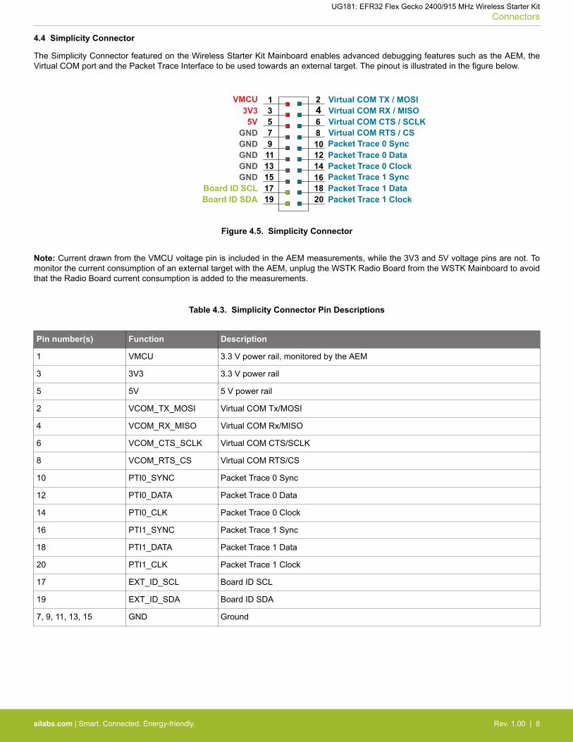
4.4 Simplicity Connector
The Simplicity Connector featured on the Wireless Starter Kit Mainboard enables advanced debugging features such as the AEM, theVirtual COM port and the Packet Trace Interface to be used towards an external target. The pinout is illustrated in the figure below.
VMCU 133V355V
15GND13GND11GND9GND7GND
17Board ID SCL19Board ID SDA
2 Virtual COM TX / MOSI4 Virtual COM RX / MISO6 Virtual COM CTS / SCLK8 Virtual COM RTS / CS10 Packet Trace 0 Sync12 Packet Trace 0 Data14 Packet Trace 0 Clock16 Packet Trace 1 Sync18 Packet Trace 1 Data20 Packet Trace 1 Clock
Figure 4.5. Simplicity Connector
Note: Current drawn from the VMCU voltage pin is included in the AEM measurements, while the 3V3 and 5V voltage pins are not. Tomonitor the current consumption of an external target with the AEM, unplug the WSTK Radio Board from the WSTK Mainboard to avoidthat the Radio Board current consumption is added to the measurements.
Table 4.3. Simplicity Connector Pin Descriptions
Pin number(s) Function Description
1 VMCU 3.3 V power rail, monitored by the AEM
3 3V3 3.3 V power rail
5 5V 5 V power rail
2 VCOM_TX_MOSI Virtual COM Tx/MOSI
4 VCOM_RX_MISO Virtual COM Rx/MISO
6 VCOM_CTS_SCLK Virtual COM CTS/SCLK
8 VCOM_RTS_CS Virtual COM RTS/CS
10 PTI0_SYNC Packet Trace 0 Sync
12 PTI0_DATA Packet Trace 0 Data
14 PTI0_CLK Packet Trace 0 Clock
16 PTI1_SYNC Packet Trace 1 Sync
18 PTI1_DATA Packet Trace 1 Data
20 PTI1_CLK Packet Trace 1 Clock
17 EXT_ID_SCL Board ID SCL
19 EXT_ID_SDA Board ID SDA
7, 9, 11, 13, 15 GND Ground
UG181: EFR32 Flex Gecko 2400/915 MHz Wireless Starter KitConnectors
silabs.com | Smart. Connected. Energy-friendly. Rev. 1.00 | 8
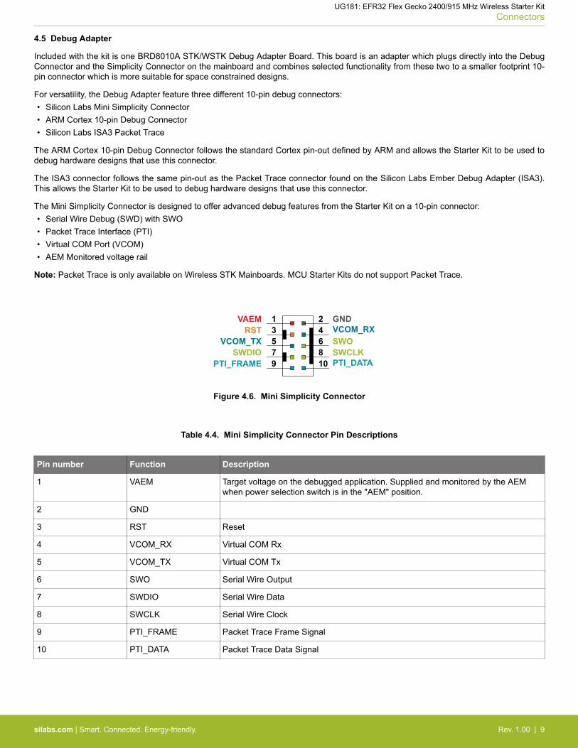
4.5 Debug Adapter
Included with the kit is one BRD8010A STK/WSTK Debug Adapter Board. This board is an adapter which plugs directly into the DebugConnector and the Simplicity Connector on the mainboard and combines selected functionality from these two to a smaller footprint 10-pin connector which is more suitable for space constrained designs.
For versatility, the Debug Adapter feature three different 10-pin debug connectors:• Silicon Labs Mini Simplicity Connector• ARM Cortex 10-pin Debug Connector• Silicon Labs ISA3 Packet Trace
The ARM Cortex 10-pin Debug Connector follows the standard Cortex pin-out defined by ARM and allows the Starter Kit to be used todebug hardware designs that use this connector.
The ISA3 connector follows the same pin-out as the Packet Trace connector found on the Silicon Labs Ember Debug Adapter (ISA3).This allows the Starter Kit to be used to debug hardware designs that use this connector.
The Mini Simplicity Connector is designed to offer advanced debug features from the Starter Kit on a 10-pin connector:• Serial Wire Debug (SWD) with SWO• Packet Trace Interface (PTI)• Virtual COM Port (VCOM)• AEM Monitored voltage rail
Note: Packet Trace is only available on Wireless STK Mainboards. MCU Starter Kits do not support Packet Trace.
VAEM 13RST5VCOM_TX
9PTI_FRAME7SWDIO
2 GND4 VCOM_RX6 SWO8 SWCLK10 PTI_DATA
Figure 4.6. Mini Simplicity Connector
Table 4.4. Mini Simplicity Connector Pin Descriptions
Pin number Function Description
1 VAEM Target voltage on the debugged application. Supplied and monitored by the AEMwhen power selection switch is in the "AEM" position.
2 GND
3 RST Reset
4 VCOM_RX Virtual COM Rx
5 VCOM_TX Virtual COM Tx
6 SWO Serial Wire Output
7 SWDIO Serial Wire Data
8 SWCLK Serial Wire Clock
9 PTI_FRAME Packet Trace Frame Signal
10 PTI_DATA Packet Trace Data Signal
UG181: EFR32 Flex Gecko 2400/915 MHz Wireless Starter KitConnectors
silabs.com | Smart. Connected. Energy-friendly. Rev. 1.00 | 9
5. Power Supply and Reset
5.1 Radio Board Power Selection
The EFR32 on a Wireless Starter Kit can be powered by one of these sources:
• the debug USB cable;• a 3V coin cell battery; or• a USB regulator on the Radio Board (for devices with USB support only).
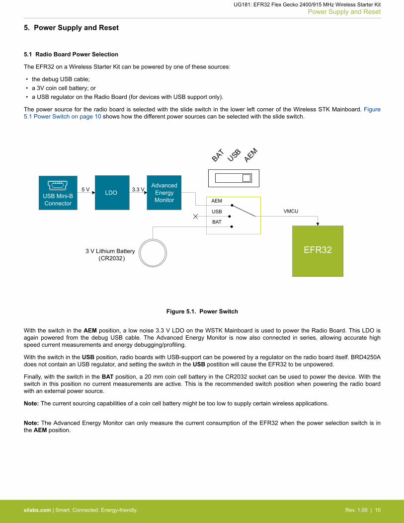
The power source for the radio board is selected with the slide switch in the lower left corner of the Wireless STK Mainboard. Figure5.1 Power Switch on page 10 shows how the different power sources can be selected with the slide switch.
VMCU
AEM
USB
BAT
USB Mini-BConnector
AdvancedEnergyMonitor
3 V Lithium Battery (CR2032)
BATUSB
AEM
LDO
EFR32
5 V 3.3 V
Figure 5.1. Power Switch
With the switch in the AEM position, a low noise 3.3 V LDO on the WSTK Mainboard is used to power the Radio Board. This LDO isagain powered from the debug USB cable. The Advanced Energy Monitor is now also connected in series, allowing accurate highspeed current measurements and energy debugging/profiling.
With the switch in the USB position, radio boards with USB-support can be powered by a regulator on the radio board itself. BRD4250Adoes not contain an USB regulator, and setting the switch in the USB postition will cause the EFR32 to be unpowered.
Finally, with the switch in the BAT position, a 20 mm coin cell battery in the CR2032 socket can be used to power the device. With theswitch in this position no current measurements are active. This is the recommended switch position when powering the radio boardwith an external power source.
Note: The current sourcing capabilities of a coin cell battery might be too low to supply certain wireless applications.
Note: The Advanced Energy Monitor can only measure the current consumption of the EFR32 when the power selection switch is inthe AEM position.
UG181: EFR32 Flex Gecko 2400/915 MHz Wireless Starter KitPower Supply and Reset
silabs.com | Smart. Connected. Energy-friendly. Rev. 1.00 | 10
5.2 Board Controller Power
The board controller is responsible for important features such as the debugger and the Advanced Energy Monitor, and is poweredexclusively through the USB port in the top left corner of the board. This part of the kit resides on a separate power domain, so a differ-ent power source can be selected for the target device while retaining debugging functionality. This power domain is also isolated toprevent current leakage from the target power domain when power to the Board Controller is removed.
The board controller power domain is exclusively supplied by the J-Link USB cable, and is not influenced by the position of the powerswitch.
The kit has been carefully designed to keep the board controller and the target power domains isolated from each other as one of thempowers down. This ensures that the target EFR32 device will continue to operate in the USB and BAT modes.
5.3 EFR32 Reset
The EFR32 Wireless SoC can be reset by a few different sources:• A user pressing the RESET button.• The on-board debugger pulling the #RESET pin low.• An external debugger pulling the #RESET pin low.
In addition to the reset sources mentioned above, the Board Controller will also issue a reset to the EFR32 when booting up. Thismeans that removing power to the Board Controller (plugging out the J-Link USB cable) will not generate a reset, but plugging the cableback in will, as the Board Controller boots up.
5.4 Battery Holder
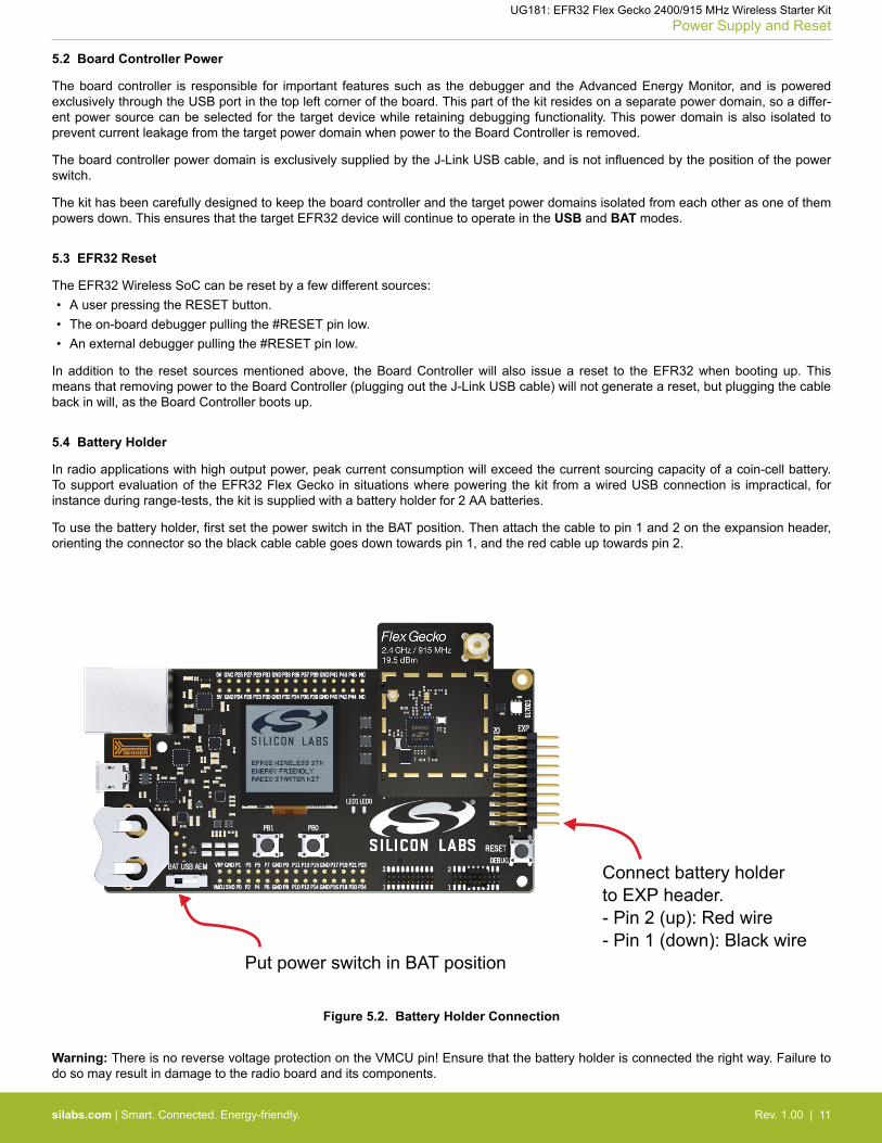
In radio applications with high output power, peak current consumption will exceed the current sourcing capacity of a coin-cell battery.To support evaluation of the EFR32 Flex Gecko in situations where powering the kit from a wired USB connection is impractical, forinstance during range-tests, the kit is supplied with a battery holder for 2 AA batteries.
To use the battery holder, first set the power switch in the BAT position. Then attach the cable to pin 1 and 2 on the expansion header,orienting the connector so the black cable cable goes down towards pin 1, and the red cable up towards pin 2.
Connect battery holderto EXP header.- Pin 2 (up): Red wire- Pin 1 (down): Black wire
Put power switch in BAT position
Figure 5.2. Battery Holder Connection
Warning: There is no reverse voltage protection on the VMCU pin! Ensure that the battery holder is connected the right way. Failure todo so may result in damage to the radio board and its components.
UG181: EFR32 Flex Gecko 2400/915 MHz Wireless Starter KitPower Supply and Reset
silabs.com | Smart. Connected. Energy-friendly. Rev. 1.00 | 11
6. Peripherals
The starter kit has a set of peripherals that showcase some of the features of the EFR32.
Be aware that most EFR32 I/O routed to peripherals are also routed to the breakout pads. This must be taken into consideration whenusing the breakout pads for your application.
6.1 Push Buttons and LEDs
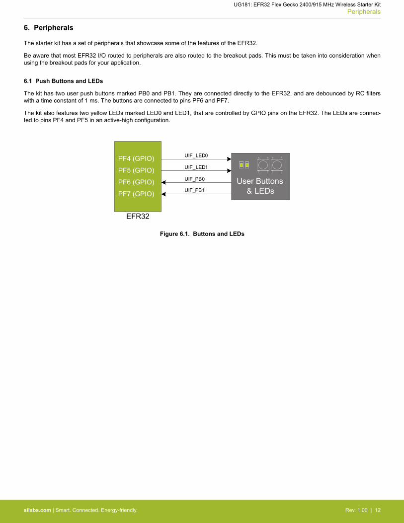
The kit has two user push buttons marked PB0 and PB1. They are connected directly to the EFR32, and are debounced by RC filterswith a time constant of 1 ms. The buttons are connected to pins PF6 and PF7.
The kit also features two yellow LEDs marked LED0 and LED1, that are controlled by GPIO pins on the EFR32. The LEDs are connec-ted to pins PF4 and PF5 in an active-high configuration.
PF5 (GPIO)User Buttons
& LEDs
UIF_LED0
UIF_LED1
UIF_PB0
UIF_PB1PF6 (GPIO)
PF7 (GPIO)
PF4 (GPIO)
EFR32
Figure 6.1. Buttons and LEDs
UG181: EFR32 Flex Gecko 2400/915 MHz Wireless Starter KitPeripherals
silabs.com | Smart. Connected. Energy-friendly. Rev. 1.00 | 12
6.2 Memory LCD-TFT Display
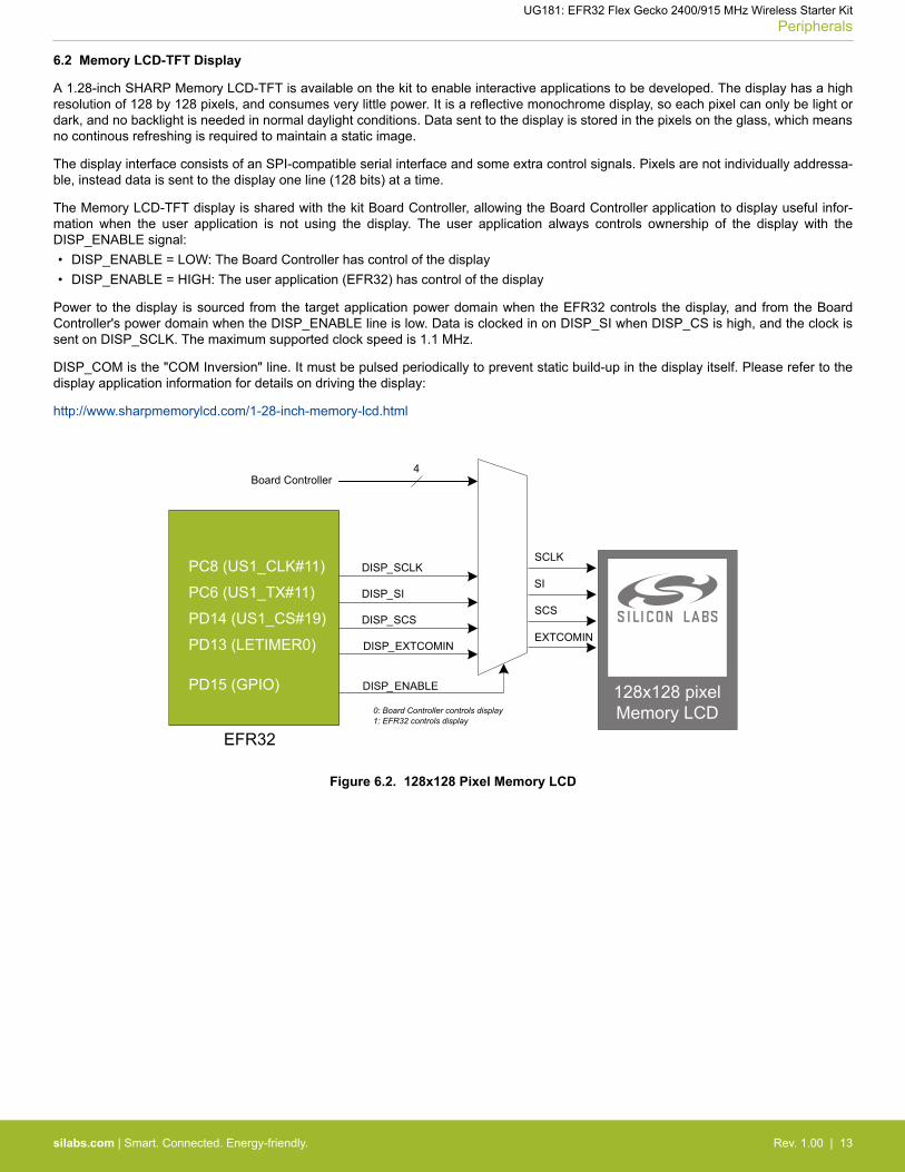
A 1.28-inch SHARP Memory LCD-TFT is available on the kit to enable interactive applications to be developed. The display has a highresolution of 128 by 128 pixels, and consumes very little power. It is a reflective monochrome display, so each pixel can only be light ordark, and no backlight is needed in normal daylight conditions. Data sent to the display is stored in the pixels on the glass, which meansno continous refreshing is required to maintain a static image.
The display interface consists of an SPI-compatible serial interface and some extra control signals. Pixels are not individually addressa-ble, instead data is sent to the display one line (128 bits) at a time.
The Memory LCD-TFT display is shared with the kit Board Controller, allowing the Board Controller application to display useful infor-mation when the user application is not using the display. The user application always controls ownership of the display with theDISP_ENABLE signal:• DISP_ENABLE = LOW: The Board Controller has control of the display• DISP_ENABLE = HIGH: The user application (EFR32) has control of the display
Power to the display is sourced from the target application power domain when the EFR32 controls the display, and from the BoardController's power domain when the DISP_ENABLE line is low. Data is clocked in on DISP_SI when DISP_CS is high, and the clock issent on DISP_SCLK. The maximum supported clock speed is 1.1 MHz.
DISP_COM is the "COM Inversion" line. It must be pulsed periodically to prevent static build-up in the display itself. Please refer to thedisplay application information for details on driving the display:
http://www.sharpmemorylcd.com/1-28-inch-memory-lcd.html
PC8 (US1_CLK#11)
PC6 (US1_TX#11)
PD14 (US1_CS#19)
PD13 (LETIMER0)
PD15 (GPIO)
EFR32
0: Board Controller controls display1: EFR32 controls display
Figure 6.2. 128x128 Pixel Memory LCD
UG181: EFR32 Flex Gecko 2400/915 MHz Wireless Starter KitPeripherals
silabs.com | Smart. Connected. Energy-friendly. Rev. 1.00 | 13
6.3 Serial Flash
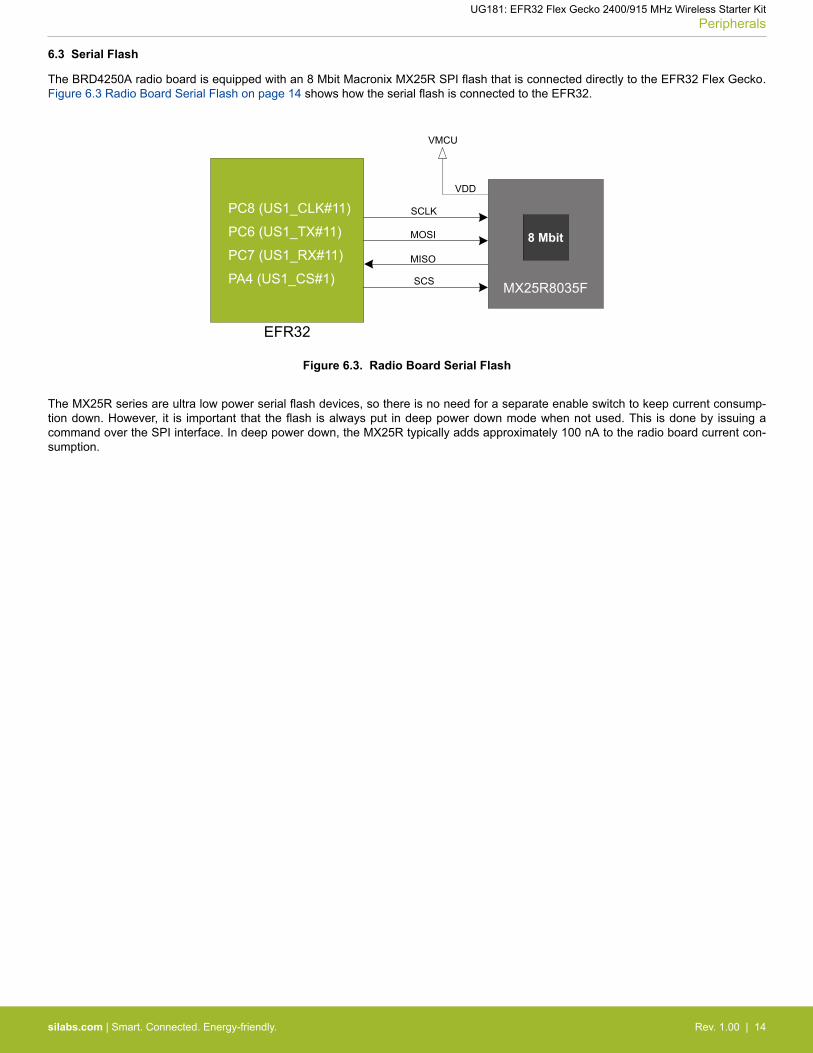
The BRD4250A radio board is equipped with an 8 Mbit Macronix MX25R SPI flash that is connected directly to the EFR32 Flex Gecko.Figure 6.3 Radio Board Serial Flash on page 14 shows how the serial flash is connected to the EFR32.
PC8 (US1_CLK#11)
PC6 (US1_TX#11)
PC7 (US1_RX#11)
PA4 (US1_CS#1)
EFR32
MX25R8035F
SCLK
MOSI
MISO
SCS
VMCU
VDD
8 Mbit
Figure 6.3. Radio Board Serial Flash
The MX25R series are ultra low power serial flash devices, so there is no need for a separate enable switch to keep current consump-tion down. However, it is important that the flash is always put in deep power down mode when not used. This is done by issuing acommand over the SPI interface. In deep power down, the MX25R typically adds approximately 100 nA to the radio board current con-sumption.
UG181: EFR32 Flex Gecko 2400/915 MHz Wireless Starter KitPeripherals
silabs.com | Smart. Connected. Energy-friendly. Rev. 1.00 | 14
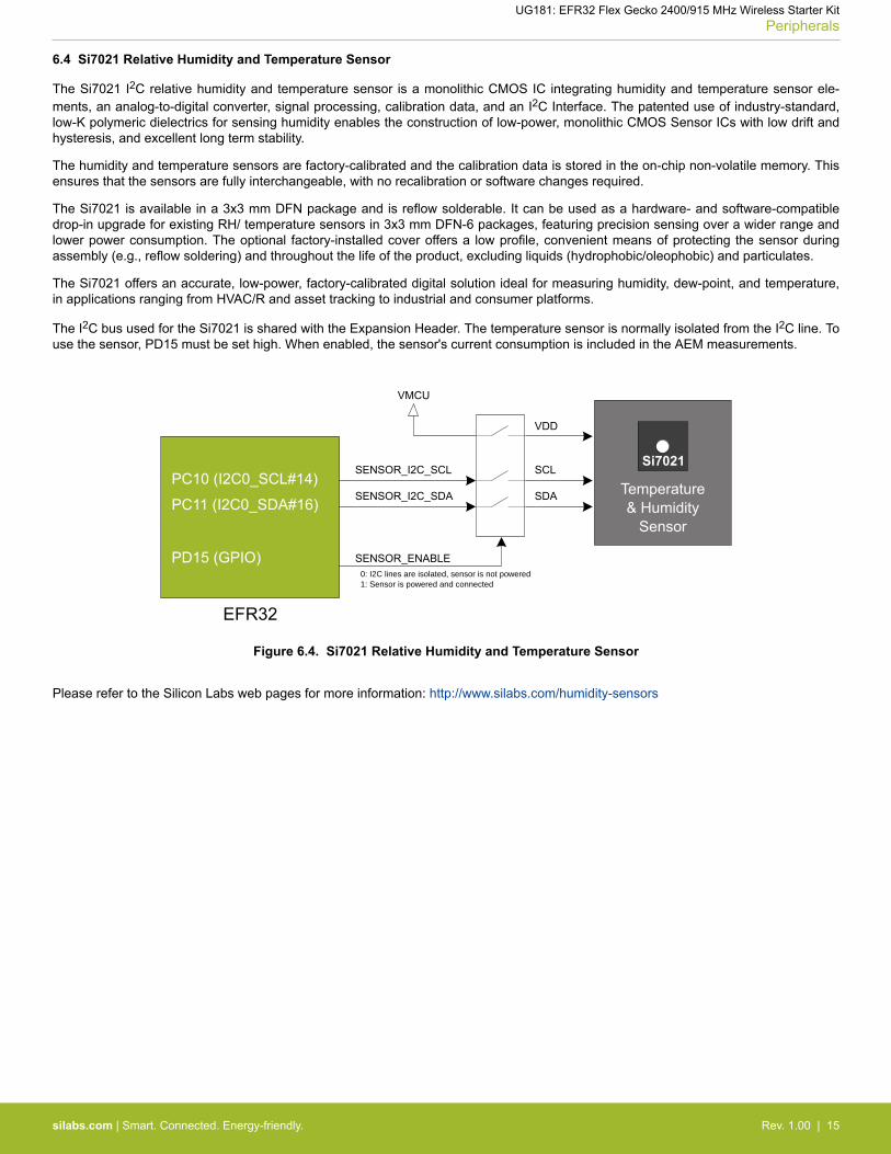
6.4 Si7021 Relative Humidity and Temperature Sensor
The Si7021 I2C relative humidity and temperature sensor is a monolithic CMOS IC integrating humidity and temperature sensor ele-ments, an analog-to-digital converter, signal processing, calibration data, and an I2C Interface. The patented use of industry-standard,low-K polymeric dielectrics for sensing humidity enables the construction of low-power, monolithic CMOS Sensor ICs with low drift andhysteresis, and excellent long term stability.
The humidity and temperature sensors are factory-calibrated and the calibration data is stored in the on-chip non-volatile memory. Thisensures that the sensors are fully interchangeable, with no recalibration or software changes required.
The Si7021 is available in a 3x3 mm DFN package and is reflow solderable. It can be used as a hardware- and software-compatibledrop-in upgrade for existing RH/ temperature sensors in 3x3 mm DFN-6 packages, featuring precision sensing over a wider range andlower power consumption. The optional factory-installed cover offers a low profile, convenient means of protecting the sensor duringassembly (e.g., reflow soldering) and throughout the life of the product, excluding liquids (hydrophobic/oleophobic) and particulates.
The Si7021 offers an accurate, low-power, factory-calibrated digital solution ideal for measuring humidity, dew-point, and temperature,in applications ranging from HVAC/R and asset tracking to industrial and consumer platforms.
The I2C bus used for the Si7021 is shared with the Expansion Header. The temperature sensor is normally isolated from the I2C line. Touse the sensor, PD15 must be set high. When enabled, the sensor's current consumption is included in the AEM measurements.
SENSOR_ENABLE0: I2C lines are isolated, sensor is not powered1: Sensor is powered and connected
PC10 (I2C0_SCL#14)
PC11 (I2C0_SDA#16)
PD15 (GPIO)
SENSOR_I2C_SDA
SENSOR_I2C_SCL
VMCU
VDD
SCL
SDA Temperature& Humidity
Sensor
EFR32
Si7021
Figure 6.4. Si7021 Relative Humidity and Temperature Sensor
Please refer to the Silicon Labs web pages for more information: http://www.silabs.com/humidity-sensors
UG181: EFR32 Flex Gecko 2400/915 MHz Wireless Starter KitPeripherals
silabs.com | Smart. Connected. Energy-friendly. Rev. 1.00 | 15
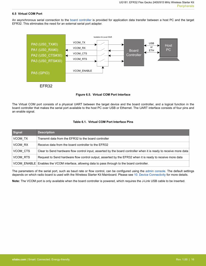
6.5 Virtual COM Port
An asynchronous serial connection to the board controller is provided for application data transfer between a host PC and the targetEFR32. This eliminates the need for an external serial port adapter.
VCOM_ENABLE
PA0 (US0_TX#0)PA1 (US0_RX#0)
PA5 (GPIO)
VCOM_RX
VCOM_TX
BoardController
EFR32
USBHostPC
Isolation & Level Shift
PA2 (US0_CTS#30)PA3 (US0_RTS#30)
VCOM_CTS
VCOM_RTS
ETHor
Figure 6.5. Virtual COM Port Interface
The Virtual COM port consists of a physical UART between the target device and the board controller, and a logical function in theboard controller that makes the serial port available to the host PC over USB or Ethernet. The UART interface consists of four pins andan enable signal.
Table 6.1. Virtual COM Port Interface Pins
Signal Description
VCOM_TX Transmit data from the EFR32 to the board controller
VCOM_RX Receive data from the board controller to the EFR32
VCOM_CTS Clear to Send hardware flow control input, asserted by the board controller when it is ready to receive more data
VCOM_RTS Request to Send hardware flow control output, asserted by the EFR32 when it is ready to receive more data
VCOM_ENABLE Enables the VCOM interface, allowing data to pass through to the board controller.
The parameters of the serial port, such as baud rate or flow control, can be configured using the admin console. The default settingsdepends on which radio board is used with the Wireless Starter Kit Mainboard. Please see 10. Device Connectivity for more details.
Note: The VCOM port is only available when the board controller is powered, which requires the J-Link USB cable to be inserted.
UG181: EFR32 Flex Gecko 2400/915 MHz Wireless Starter KitPeripherals
silabs.com | Smart. Connected. Energy-friendly. Rev. 1.00 | 16
7. Board Controller
The Wireless Starter Kit Mainboard contains a microcontroller separate from the EFR32 Flex Gecko that is responsible for some of theadvanced kit features provided. This microcontroller is referred to as the "Board Controller", and is not programmable by the user. Theboard controller acts as an interface between the host PC and the target device on the radio board, as well as handling some house-keeping functions on the board.
Some of the kit features actively managed by the board controller are:
• The On-board Debugger, which can flash and debug both on-board and external targets.• The Advanced Energy Monitor, which provides real-time energy profiling of the user application.• The Packet Trace Interface , which is used in conjunction with PC software to provide detailed insight into an active radio network.• The Virtual COM Port and Virtual UART interfaces, which provide ways to transfer application data between the host PC and the
target processor.• The Admin Console, which provides configuration of the various board features.
Silicon Labs publishes updates to the board controller firmware in form of firmware upgrade packages. These updates may enable newfeatures or fix issues. See 11.2 Firmware Upgrades for details on firmware upgrade.
7.1 Admin Console
The admin console is a command line interface to the board controller on the kit. It provides functionality for configuring the kit behaviorand retreiving configuration and operational parameters.
■ Connecting
The SLWSTK6060A must be connected to Ethernet using the Ethernet connector in the top left corner of the mainboard for the adminconsole to be available. See ● Ethernet Interface for details on the Ethernet connectivity.
Connect to the Admin Console by opening a telnet connection to the kit's IP address, port number 4902.
When successfully connected, a WSTK> prompt is displayed.
UG181: EFR32 Flex Gecko 2400/915 MHz Wireless Starter KitBoard Controller
silabs.com | Smart. Connected. Energy-friendly. Rev. 1.00 | 17
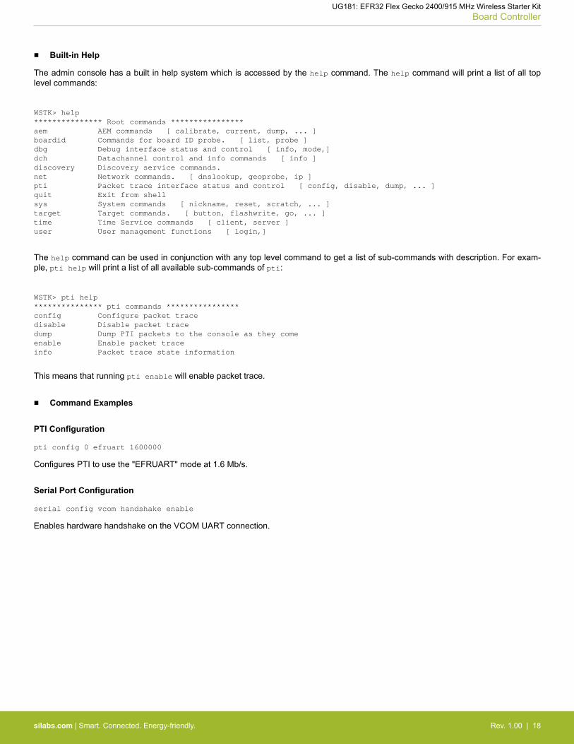
■ Built-in Help
The admin console has a built in help system which is accessed by the help command. The help command will print a list of all toplevel commands:
WSTK> help*************** Root commands ****************aem AEM commands [ calibrate, current, dump, ... ]boardid Commands for board ID probe. [ list, probe ]dbg Debug interface status and control [ info, mode,]dch Datachannel control and info commands [ info ]discovery Discovery service commands.net Network commands. [ dnslookup, geoprobe, ip ]pti Packet trace interface status and control [ config, disable, dump, ... ]quit Exit from shellsys System commands [ nickname, reset, scratch, ... ]target Target commands. [ button, flashwrite, go, ... ]time Time Service commands [ client, server ]user User management functions [ login,]
The help command can be used in conjunction with any top level command to get a list of sub-commands with description. For exam-ple, pti help will print a list of all available sub-commands of pti:
WSTK> pti help*************** pti commands ****************config Configure packet tracedisable Disable packet tracedump Dump PTI packets to the console as they comeenable Enable packet traceinfo Packet trace state information
This means that running pti enable will enable packet trace.
■ Command Examples
PTI Configuration
pti config 0 efruart 1600000
Configures PTI to use the "EFRUART" mode at 1.6 Mb/s.
Serial Port Configuration
serial config vcom handshake enable
Enables hardware handshake on the VCOM UART connection.
UG181: EFR32 Flex Gecko 2400/915 MHz Wireless Starter KitBoard Controller
silabs.com | Smart. Connected. Energy-friendly. Rev. 1.00 | 18
8. Advanced Energy Monitor
8.1 Introduction
Any embedded developer seeking to make his embedded code spend as little energy as the underlying architecture supports, needstools to easily and quickly discover inefficiencies in the running application.
This is what the Simplicity Energy Profiler is designed to do. It will in real-time graph and log current as a function of time while correlat-ing this to the actual target application code running on the EFR32. There are multiple features in the profiler software that allows foreasy analysis, such as markers and statistics on selected regions of the current graph or aggregate energy usage by different parts ofthe application.
8.2 Theory of Operation
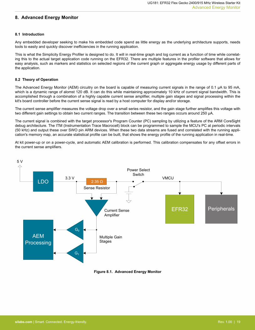
The Advanced Energy Monitor (AEM) circuitry on the board is capable of measuring current signals in the range of 0.1 µA to 95 mA,which is a dynamic range of alomst 120 dB. It can do this while maintaining approximately 10 kHz of current signal bandwidth. This isaccomplished through a combination of a highly capable current sense amplifier, multiple gain stages and signal processing within thekit's board controller before the current sense signal is read by a host computer for display and/or storage.
The current sense amplifier measures the voltage drop over a small series resistor, and the gain stage further amplifies this voltage withtwo different gain settings to obtain two current ranges. The transition between these two ranges occurs around 250 µA.
The current signal is combined with the target processor's Program Counter (PC) sampling by utilizing a feature of the ARM CoreSightdebug architecture. The ITM (Instrumentation Trace Macrocell) block can be programmed to sample the MCU's PC at periodic intervals(50 kHz) and output these over SWO pin ARM devices. When these two data streams are fused and correlated with the running appli-cation's memory map, an accurate statistical profile can be built, that shows the energy profile of the running application in real-time.
At kit power-up or on a power-cycle, and automatic AEM calibration is performed. This calibration compensates for any offset errors inthe current sense amplifiers.
EFR32
LDO
Peripherals
AEMProcessing
Figure 8.1. Advanced Energy Monitor
UG181: EFR32 Flex Gecko 2400/915 MHz Wireless Starter KitAdvanced Energy Monitor
silabs.com | Smart. Connected. Energy-friendly. Rev. 1.00 | 19
8.3 AEM Accuracy and Performance
The AEM is capable of measuring currents in the range of 0.1 µA to 95 mA. For currents above 250 µA, the AEM is accurate within 0.1mA. When measuring currents below 250 µA, the accuracy increases to 1 µA. Even though the absolute accuracy is 1 µA in the sub250 µA range, the AEM is able to detect changes in the current consumption as small as 100 nA.
The AEM current sampling rate is 10 kHz.
Note: The AEM circuitry only works when the kit is powered and the power switch is in the AEM position.
8.4 Usage
The AEM data is collected by the board controller and can be displayed by the Energy Profiler, available through Simplicity Studio. Byusing the Energy Profiler, current consumption and voltage can be measured and linked to the actual code running on the EFR32 inrealtime.
UG181: EFR32 Flex Gecko 2400/915 MHz Wireless Starter KitAdvanced Energy Monitor
silabs.com | Smart. Connected. Energy-friendly. Rev. 1.00 | 20
9. On-Board Debugger
The SLWSTK6060A contains an integrated debugger, which can be used to download code and debug the EFR32. In addition to pro-gramming the EFR32 on the kit, the debugger can also be used to program and debug external Silicon Labs EFM32, EFM8, EZR32and EFR32 devices.
The debugger supports three different debug interfaces used with Silicon Labs devices:• Serial Wire Debug, is used with all EFM32, EFR32 and EZR32 devices• JTAG, which can be used with some newer EFR32 and EFM32 devices• C2 Debug, which is used with EFM8 devices
In order for debugging to work properly, make sure you have the approriate debug interface selected that works with your device. Thedebug connector on the board supports all three of these modes.
9.1 Host Interfaces
The SLWSTK6060A supports connecting to the on-board debugger using either Ethernet or USB.
Many tools support connecting to a debugger using either USB or Ethernet. When connected over USB, the kit is identified by its J-Linkserial number. When connected over Ethernet, the kit is normally identified by its IP address. Some tools also support using the serialnumber when connecting over Ethernet, this typically require the computer and the kit to be on the same subnet for the discovery proto-col (using UDP broadcast packets) to work.
USB Interface
The USB interface is available whenever the mini-B USB connector on the left hand side of the kit is connected to a computer.
Ethernet Interface
The Ethernet interface is available when the kit's Ethernet connector in the top left corner is connected to a network. Normally, the kitwill receive an IP address from a local DHCP server, and the IP address is printed on the LCD display. If your network does not have aDHCP server, you need to connect to the kit via USB and set the IP address manually using Simplicity Studio, Simplicity Commander orJ-Link Configurator.
For the Ethernet connectivity to work, the kit must still be powered through the mini-B USB connector. See 5.2 Board Controller Powerfor details.
Serial Number Identification
All Silicon Labs kits have a unique J-Link serial number which can identifies the kit to PC applications. This number is 9 digits, and isnormally on the form 44xxxxxxx.
The J-Link serial number is normally printed at the bottom of the kit LCD display.
UG181: EFR32 Flex Gecko 2400/915 MHz Wireless Starter KitOn-Board Debugger
silabs.com | Smart. Connected. Energy-friendly. Rev. 1.00 | 21
9.2 Debug Modes
Programming external devices is done by connecting to a target board through the provided Debug IN/OUT Connector, and by settingthe debug mode to [Out]. The same connector can also be used to connect an external debugger to the EFR32 Wireless SoC on thekit, by setting the debug mode to [In]. A summary of the different supported debug modes is given in 9.2 Debug Modes.
Selecting the active debug mode is done with a drop-down menu in the Kit Manager tool in Simplicity Studio.
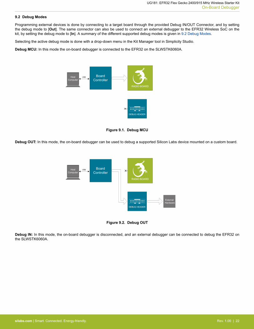
Debug MCU: In this mode the on-board debugger is connected to the EFR32 on the SLWSTK6060A.
RADIO BOARD
BoardController
USBHostComputer
DEBUG HEADER
External Hardware
Figure 9.1. Debug MCU
Debug OUT: In this mode, the on-board debugger can be used to debug a supported Silicon Labs device mounted on a custom board.
BoardController
USBHostComputer
DEBUG HEADER
External Hardware
RADIO BOARD
Figure 9.2. Debug OUT
Debug IN: In this mode, the on-board debugger is disconnected, and an external debugger can be connected to debug the EFR32 onthe SLWSTK6060A.
UG181: EFR32 Flex Gecko 2400/915 MHz Wireless Starter KitOn-Board Debugger
silabs.com | Smart. Connected. Energy-friendly. Rev. 1.00 | 22
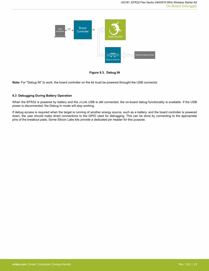
BoardController
USBHostComputer
DEBUG HEADER
External Debug Probe
RADIO BOARD
Figure 9.3. Debug IN
Note: For "Debug IN" to work, the board controller on the kit must be powered throught the USB connector.
9.3 Debugging During Battery Operation
When the EFR32 is powered by battery and the J-Link USB is still connected, the on-board debug functionality is available. If the USBpower is disconnected, the Debug In mode will stop working.
If debug access is required when the target is running of another energy source, such as a battery, and the board controller is powereddown, the user should make direct connections to the GPIO used for debugging. This can be done by connecting to the appropriatepins of the breakout pads. Some Silicon Labs kits provide a dedicated pin header for this purpose.
UG181: EFR32 Flex Gecko 2400/915 MHz Wireless Starter KitOn-Board Debugger
silabs.com | Smart. Connected. Energy-friendly. Rev. 1.00 | 23

10. Device Connectivity
The SLWSTK6060A provides several convenient ways to communicate with a target application without soldering or using externalhardware.
10.1 Virtual COM Port
When the target device drives the VCOM_ENABLE (PA5) signal high, a communication line to the Board Controller is enabled. Thetarget can then communicate to the host computer via the Board Controller using USART0, Location 0 (TX pin PA0, RX pin PA1).
When enabling VCOM, the Board Controller makes communication to the host computer possible on the following interfaces:• Virtual USB serial port using a CDC driver.• TCP/IP, by connecting to the Wireless STK on port 4901 with a Telnet client.
Note: Only one of these can be used at the same time, meaning that if a socket is connected to port 4901, no data can be sent orreceived on the USB COM port.
10.2 Virtual UART
The Virtual UART port outputs data that the target application outputs over SWO, ITM channel 0.
UG181: EFR32 Flex Gecko 2400/915 MHz Wireless Starter KitDevice Connectivity
silabs.com | Smart. Connected. Energy-friendly. Rev. 1.00 | 24
11. Kit Manager and Upgrades
The Kit Manager is a program that comes with Simplicity Studio. It can perform various kit and EFR32 specific tasks.
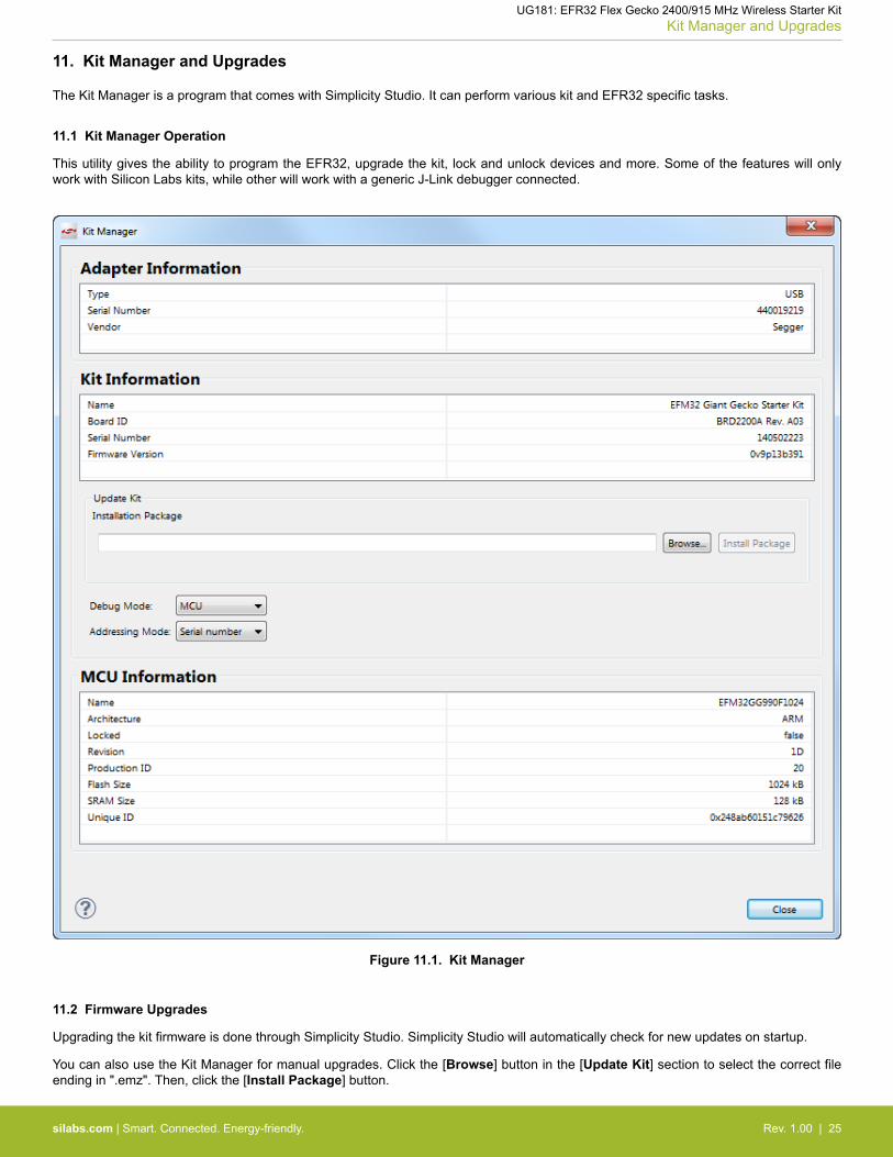
11.1 Kit Manager Operation
This utility gives the ability to program the EFR32, upgrade the kit, lock and unlock devices and more. Some of the features will onlywork with Silicon Labs kits, while other will work with a generic J-Link debugger connected.
Figure 11.1. Kit Manager
11.2 Firmware Upgrades
Upgrading the kit firmware is done through Simplicity Studio. Simplicity Studio will automatically check for new updates on startup.
You can also use the Kit Manager for manual upgrades. Click the [Browse] button in the [Update Kit] section to select the correct fileending in ".emz". Then, click the [Install Package] button.
UG181: EFR32 Flex Gecko 2400/915 MHz Wireless Starter KitKit Manager and Upgrades
silabs.com | Smart. Connected. Energy-friendly. Rev. 1.00 | 25

12. Schematics, Assembly Drawings and BOM
The schematics, assembly drawings and bill of materials (BOM) for the hardware included in the EFR32 Flex Gecko 2400/915 MHzWireless Starter Kit are available through Simplicity Studio when the kit documentation package has been installed.
UG181: EFR32 Flex Gecko 2400/915 MHz Wireless Starter KitSchematics, Assembly Drawings and BOM
silabs.com | Smart. Connected. Energy-friendly. Rev. 1.00 | 26
13. Kit Revision History and Errata
13.1 Revision History
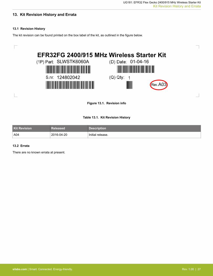
The kit revision can be found printed on the box label of the kit, as outlined in the figure below.
SLWSTK6060AEFR32FG 2400/915 MHz Wireless Starter Kit
124802042
01-04-16
A03
Figure 13.1. Revision info
Table 13.1. Kit Revision History
Kit Revision Released Description
A04 2016-04-20 Initial release.
13.2 Errata
There are no known errata at present.
UG181: EFR32 Flex Gecko 2400/915 MHz Wireless Starter KitKit Revision History and Errata
silabs.com | Smart. Connected. Energy-friendly. Rev. 1.00 | 27
14. Document Revision History
Revision 1.00
2016-05-23
Initial document release.
UG181: EFR32 Flex Gecko 2400/915 MHz Wireless Starter KitDocument Revision History
silabs.com | Smart. Connected. Energy-friendly. Rev. 1.00 | 28
Table of Contents1. Introduction . . . . . . . . . . . . . . . . . . . . . . . . . . . . . . . . 1
1.1 Kit Contents . . . . . . . . . . . . . . . . . . . . . . . . . . . . . . 1
1.2 Getting Started . . . . . . . . . . . . . . . . . . . . . . . . . . . . . 1
2. Kit Hardware Layout . . . . . . . . . . . . . . . . . . . . . . . . . . . . 2
3. Kit Block Diagram . . . . . . . . . . . . . . . . . . . . . . . . . . . . . 3
4. Connectors . . . . . . . . . . . . . . . . . . . . . . . . . . . . . . . . 44.1 Breakout Pads . . . . . . . . . . . . . . . . . . . . . . . . . . . . . 4
4.2 Expansion Header . . . . . . . . . . . . . . . . . . . . . . . . . . . . 54.2.1 Expansion Header Pin-out . . . . . . . . . . . . . . . . . . . . . . . . . 6
4.3 Debug Connector. . . . . . . . . . . . . . . . . . . . . . . . . . . . . 7
4.4 Simplicity Connector. . . . . . . . . . . . . . . . . . . . . . . . . . . . 8
4.5 Debug Adapter . . . . . . . . . . . . . . . . . . . . . . . . . . . . . 9
5. Power Supply and Reset . . . . . . . . . . . . . . . . . . . . . . . . . . 105.1 Radio Board Power Selection . . . . . . . . . . . . . . . . . . . . . . . .10
5.2 Board Controller Power. . . . . . . . . . . . . . . . . . . . . . . . . . .11
5.3 EFR32 Reset . . . . . . . . . . . . . . . . . . . . . . . . . . . . . .11
5.4 Battery Holder . . . . . . . . . . . . . . . . . . . . . . . . . . . . . .11
6. Peripherals . . . . . . . . . . . . . . . . . . . . . . . . . . . . . . . 126.1 Push Buttons and LEDs . . . . . . . . . . . . . . . . . . . . . . . . . .12
6.2 Memory LCD-TFT Display. . . . . . . . . . . . . . . . . . . . . . . . . .13
6.3 Serial Flash . . . . . . . . . . . . . . . . . . . . . . . . . . . . . .14
6.4 Si7021 Relative Humidity and Temperature Sensor . . . . . . . . . . . . . . . . .15
6.5 Virtual COM Port . . . . . . . . . . . . . . . . . . . . . . . . . . . . .16
7. Board Controller . . . . . . . . . . . . . . . . . . . . . . . . . . . . . 177.1 Admin Console . . . . . . . . . . . . . . . . . . . . . . . . . . . . .17
8. Advanced Energy Monitor . . . . . . . . . . . . . . . . . . . . . . . . . 198.1 Introduction. . . . . . . . . . . . . . . . . . . . . . . . . . . . . . .19
8.2 Theory of Operation . . . . . . . . . . . . . . . . . . . . . . . . . . . .19
8.3 AEM Accuracy and Performance . . . . . . . . . . . . . . . . . . . . . . .20
8.4 Usage . . . . . . . . . . . . . . . . . . . . . . . . . . . . . . . .20
9. On-Board Debugger . . . . . . . . . . . . . . . . . . . . . . . . . . . . 219.1 Host Interfaces . . . . . . . . . . . . . . . . . . . . . . . . . . . . .21
9.2 Debug Modes . . . . . . . . . . . . . . . . . . . . . . . . . . . . . .22
9.3 Debugging During Battery Operation . . . . . . . . . . . . . . . . . . . . . .23
10. Device Connectivity . . . . . . . . . . . . . . . . . . . . . . . . . . . 24
Table of Contents 29
10.1 Virtual COM Port . . . . . . . . . . . . . . . . . . . . . . . . . . . .24
10.2 Virtual UART . . . . . . . . . . . . . . . . . . . . . . . . . . . . . .24
11. Kit Manager and Upgrades . . . . . . . . . . . . . . . . . . . . . . . . . 2511.1 Kit Manager Operation . . . . . . . . . . . . . . . . . . . . . . . . . .25
11.2 Firmware Upgrades . . . . . . . . . . . . . . . . . . . . . . . . . . .25
12. Schematics, Assembly Drawings and BOM . . . . . . . . . . . . . . . . . . 26
13. Kit Revision History and Errata . . . . . . . . . . . . . . . . . . . . . . . 2713.1 Revision History. . . . . . . . . . . . . . . . . . . . . . . . . . . . .27
13.2 Errata . . . . . . . . . . . . . . . . . . . . . . . . . . . . . . . .27
14. Document Revision History . . . . . . . . . . . . . . . . . . . . . . . . 28
Table of Contents . . . . . . . . . . . . . . . . . . . . . . . . . . . . . . 29
Table of Contents 30

http://www.silabs.com
Silicon Laboratories Inc.
400 West Cesar Chavez
Austin, TX 78701
USA
Simplicity Studio
One-click access to MCU and
wireless tools, documentation,
software, source code libraries &
more. Available for Windows,
Mac and Linux!
IoT Portfolio
www.silabs.com/IoTSW/HW
www.silabs.com/simplicity
Qualitywww.silabs.com/quality
Support and Communitycommunity.silabs.com
Disclaimer
Silicon Laboratories intends to provide customers with the latest, accurate, and in-depth documentation of all peripherals and modules available for system and software implementers using
or intending to use the Silicon Laboratories products. Characterization data, available modules and peripherals, memory sizes and memory addresses refer to each specific device, and
"Typical" parameters provided can and do vary in different applications. Application examples described herein are for illustrative purposes only. Silicon Laboratories reserves the right to
make changes without further notice and limitation to product information, specifications, and descriptions herein, and does not give warranties as to the accuracy or completeness of the
included information. Silicon Laboratories shall have no liability for the consequences of use of the information supplied herein. This document does not imply or express copyright licenses
granted hereunder to design or fabricate any integrated circuits. The products are not designed or authorized to be used within any Life Support System without the specific written consent
of Silicon Laboratories. A "Life Support System" is any product or system intended to support or sustain life and/or health, which, if it fails, can be reasonably expected to result in significant
personal injury or death. Silicon Laboratories products are not designed or authorized for military applications. Silicon Laboratories products shall under no circumstances be used in
weapons of mass destruction including (but not limited to) nuclear, biological or chemical weapons, or missiles capable of delivering such weapons.
Trademark Information
Silicon Laboratories Inc.® , Silicon Laboratories®, Silicon Labs®, SiLabs® and the Silicon Labs logo®, Bluegiga®, Bluegiga Logo®, Clockbuilder®, CMEMS®, DSPLL®, EFM®, EFM32®,
EFR, Ember®, Energy Micro, Energy Micro logo and combinations thereof, "the world�s most energy friendly microcontrollers", Ember®, EZLink®, EZRadio®, EZRadioPRO®, Gecko®,
ISOmodem®, Precision32®, ProSLIC®, Simplicity Studio®, SiPHY®, Telegesis, the Telegesis Logo®, USBXpress® and others are trademarks or registered trademarks of Silicon Laborato-
ries Inc. ARM, CORTEX, Cortex-M3 and THUMB are trademarks or registered trademarks of ARM Holdings. Keil is a registered trademark of ARM Limited. All other products or brand
names mentioned herein are trademarks of their respective holders.