Embed Size (px)
Citation preview

EFM Mad Mouse Pro - Midi Synthesizer
V1.0 (C) 2001 EFM Synthesizers
Assembly and Setup Manual
The Mad Mouse-Pro is a midi controlled analog synthesizer. It is designed to be built as a small stomp-box sized analog so that itcan be positioned on top of your master midi controller for easy access to it's controls. The Mad Mouse story started in late 1998when I decided to design a small inexpensive analog synthesizer that could be built for under $50 dollars. I wasn't entirelysuccessful in a lot of ways. First of all it requires a separate midi to control voltage converter that cost more that the synthesizer didand I went over budget by about $20 dollars. Still....it was a working analog synthesizer for under $200 dollars and that includedabout $100 bucks for the separate midi converter.
The MM-pro contains an on-board midi to cv converter, a +/-12 +5V power supply, two Odyssey type oscillators, one MS20 2-poleresonate VCF , two LM13600 VCAs and one MS10 type LFO.
The MM-pro's midi converter responds to midi pitch, pitch bend, mod, key-gate and glide-gate. The midi messages are convertedto control voltages. These voltages are used to control the analog sections of the synthesizer.
Mad Mouse Pro - Parts List
Board Location Product Name Source Qty Used Unit Price TotalPrice
Capacitors
C3, C4, C5, C6, C27 Capacitor - Ceramic 0.1 uF Mouser 140-50q9-104z 5 $0.18 $0.90
C9 Capacitor - Ceramic 10 pF Mouser 140-50N5-100J 1 $0.06 $0.06

C7, C8 Capacitor - Ceramic 22 pF Mouser 140-50N5-220J 2 $0.06 $0.12
C28, C29 Capacitor - Ceramic .001 uF Mouser 140-50p2-102k 2 $0.09 $0.18
C10, C17 Capacitor - Ceramic .01 uF Mouser 140-50p5-103k 2 $0.14 $0.28
C22, C23, C25, C26 Capacitor - Electrolytic 10 uF Mouser 140-XRL25V10 4 $0.05 $0.20
C24 Capacitor - Electrolytic 100 uF Mouser 140-XRL25V100 1 $0.07 $0.07
C1, C2 Capacitor - Electrolytic 470 uF Mouser 140-XRL50V470 2 $0.37 $0.74
C16 Capacitor - Monolithic 1 uF Mouser 539-CK06105K 1 $3.71 $3.71
C11 ,C12, C13, C14,C15
Capacitor - Monolithic 0.1 uF Mouser 539-CK05103K 5 $0.43 $2.15
C20, C21 Capacitor - Polyester .0022 uF Mouser 140-PF2A222J 2 $0.12 $0.24
C18, C19 Capacitor - Polyester .01 uF Mouser 140-PF2A103J 2 $0.14 $0.28
Connectors
J4 Connector - 1/4" Panel Jack *1/4" Jack
Mouser 502-11 1 $2.00 $2.00
J1 Connector - 2.5mm AC jack Mouser 161-0725 1 $0.74 $0.74
J3, J2 Connector - DIN 5-Pin PCB Mouser 161-0503 2 $1.69 $3.38
Diodes
LED2 Diode - LED 5.0mm * LED104Green
Mouser 604-L53GD 1 $0.19 $0.19
LED1 Diode - LED 5.0mm * LED105Red
Mouser 604-L53HD 1 $0.16 $0.16
D1, D2 Diode - Rectifier 1N4001 Mouser 583-1N4001 2 $0.03 $0.06
D3- D20 Diode - Signal * 1N4148 Mouser 78-1N4148 17 $0.50 $8.50
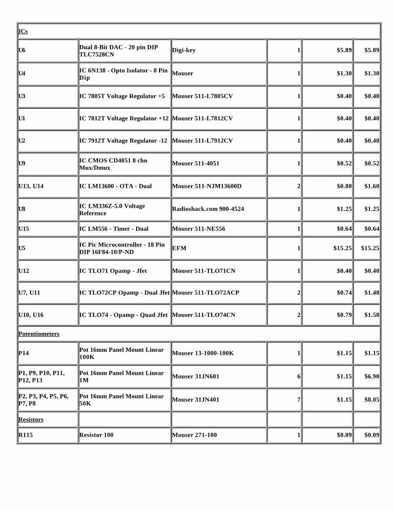
ICs
U6 Dual 8-Bit DAC - 20 pin DIPTLC7528CN
Digi-key 1 $5.89 $5.89
U4 IC 6N138 - Opto Isolator - 8 PinDip
Mouser 1 $1.30 $1.30
U3 IC 7805T Voltage Regulator +5 Mouser 511-L7805CV 1 $0.40 $0.40
U1 IC 7812T Voltage Regulator +12 Mouser 511-L7812CV 1 $0.40 $0.40
U2 IC 7912T Voltage Regulator -12 Mouser 511-L7912CV 1 $0.40 $0.40
U9 IC CMOS CD4051 8 chnMux/Dmux
Mouser 511-4051 1 $0.52 $0.52
U13, U14 IC LM13600 - OTA - Dual Mouser 511-NJM13600D 2 $0.80 $1.60
U8 IC LM336Z-5.0 VoltageReference
Radioshack.com 900-4524 1 $1.25 $1.25
U15 IC LM556 - Timer - Dual Mouser 511-NE556 1 $0.64 $0.64
U5 IC Pic Microcontroller - 18 PinDIP 16F84-10/P-ND
EFM 1 $15.25 $15.25
U12 IC TLO71 Opamp - Jfet Mouser 511-TLO71CN 1 $0.40 $0.40
U7, U11 IC TLO72CP Opamp - Dual Jfet Mouser 511-TLO72ACP 2 $0.74 $1.48
U10, U16 IC TLO74 - Opamp - Quad Jfet Mouser 511-TLO74CN 2 $0.79 $1.58
Potentiometers
P14 Pot 16mm Panel Mount Linear100K
Mouser 13-1000-100K 1 $1.15 $1.15
P1, P9, P10, P11,P12, P13
Pot 16mm Panel Mount Linear1M
Mouser 31JN601 6 $1.15 $6.90
P2, P3, P4, P5, P6,P7, P8
Pot 16mm Panel Mount Linear50K
Mouser 31JN401 7 $1.15 $8.05
Resistors
R115 Resistor 100 Mouser 271-100 1 $0.09 $0.09

R29, R35, R40, R41,R44, R46, R48, R58,R63, R66, R67, R70,R72, R82, R89, R90
Resistor 100K Mouser 271-100K 17 $0.09 $1.53
R4, R5, R7, R16,R17, R18, R19, R20,R21, R22, R23, R24,R25, R30,R33,R36,R38, R52,R55, R76, R79, R87,R88, R93, R94, R95,R98, R99, R101,R103, 104,R105,R106, R111, R113,R118, R122, R126,R128
Resistor 10K Mouser 271-10K 39 $0.09 $3.51
R43 Resistor 150K Mouser 271-150K 1 $0.09 $0.09
R3, R45, R47, R50,R69, R71, R74, R116,R117, R120
Resistor 1K Mouser 271-1.0K 10 $0.09 $0.90
R45,R69 Resistor 1K Tempco EFM 2 $5.00
R39 Resistor 1M Mouser 271-1.0M 1 $0.09 $0.09
R2, R9, R10, R91,R92, R96, R97, R108,R109, R123, R124
Resistor 220 Mouser 271-220 9 $0.09 $0.99
R64,65 Resistor 220K Mouser 271-220K 2 $0.09 $0.99
R42, R53, R54, R68,R77, R78, R64, R65
Resistor 22K Mouser 271-22K 8 $0.09 $0.72
R1, R27, R28, R32,R34, R102, R112,R114, R121, R127
Resistor 2.2K Mouser 271-2.2K 9 $0.09 $0.81
R110, R119, R125 Resistor 33K Mouser 271-33K 4 $0.09 $0.36
R6, R8 Resistor 3.3K Mouser 271-3.3K 2 $0.09 $0.18
R59, R60, R83, R84 Resistor 470K Mouser 271-470K 4 $0.09 $0.36
R26, R56, R57, R61,R62, R80, R81, R85,R86, R107
Resistor 47K Mouser 271-47K 9 $0.09 $0.81
R11, R12, R13, R14,R15, R31, R37, R49,R51, R73, R75, R100
Resistor 4.7K Mouser 271-4.7K 12 $0.09 $1.08
R129, R130, R131, Resistor 62K Mouser 271-62K 4 $0.09 $0.36

R132
Switches
S1 Switch - Mini Toggle on/offSPST
Mouser 10TC220 1 $1.70 $1.70
S3, S4 Switch - Mini Toggle on/onDPDT
Mouser 10TC260 2 $2.58 $5.16
S5, S6 Switch - Mini Toggle on/onSPDT
Mouser 10TC230 2 $1.88 $3.76
S2 Switch 4X Dip 4X DIP RA Mouser 571-4358023 1 $1.79 $1.79
Transistors
Q15, Q19, Q24, Q28,Q29
Transistor - 2N3819 N Fet (J112) Mouser 610-2N3819 5 $0.55 $2.70
Q1, Q13, Q18, Q21,Q22, Q27, Q31, Q32,Q33, Q34
Transistor - 2N3906 GP NPN Mouser 625-2N3906 10 $0.10 $1.00
Q2, Q3, Q4, Q5, Q6,Q7, Q8, Q9, Q10,Q11, Q14, Q16, Q17,Q2O, Q23, Q25, Q26,Q30
Transistor - 2N3904 GP PNP Mouser 625-2N3904 18 $0.10 $1.80
Q12 Transistor - 2N5460 P Fet Mouser 610-2N5460 1 $0.36 $0.36
Trimmers
T1, T2, T3, T4, T5,T6, T7
Trimmer - Multiturn Cermet50K
Mouser 72-T93YA-50K 7 $1.20 $8.40
Initial Assembly
If you want to install a power jack extra holes will need to be drilled in thelarge power-pads. Drill a hole on each side of the current hole in thedirection of the jack terminals and use a sharp pointed x-acto knife to cut outthe space between the holes.

Color Value Multiplier Tolerance%
Black 0 1 +/- 20
Brown 1 10 +/- 1
Red 2 100 +/- 2
Orange 3 1,000 +/- 3
Yellow 4 10,000 +/- 4
Green 5 100,000 -
Blue 6 1,000,000 -
Violet 7 10,000,000 -
Gray 8 100,000,000 -
White 9 -
Gold - 0.1 +/- 5
Install all of the resistors except R45 and R69. Silver - 0.01 +/- 10
No Color - +/- 20
Install all of the diodes. We'll get to the LEDs later. NOTE: that thepad for the anode (the side without the stripe) of D4 does not go toground as it should. Do not use this pad, instead connect it to the leadcoming off the anode of D20 it does go to ground as it should.

Install IC sockets in all spaces marked for ICs. NOTE: DO NOT INSTALL THE ICS YET.
Install all Jumpers (15) except the one that’s next to R62 and thejumper next to PAD-C2 and R85. These two jumpers will be installedafter the midi converter is working. They supply power to the analogsections on the board. As long as these are dis-connected the VCOs,filter, amps and egs will not work.
Install all of the capacitors.
Mono Cap Ceramic Cap Electrolytic Cap Polyester Cap
I have been using strips of 0.1 break-away pcb pin headers for all pads onrecent projects. This gives a convent place to solder to or connect your testprobe. The Mouser # for a 36 contact long tail pin strip header is.517-834-03-36 $0.83ea. I urge you to use these instead of wiring directly to theboard. The tail is long enough so there is still room to solder even if the pinis placed through the under side of the board.

Install the trimmers and DIP switch S2. You can use less expensive trimmers for T4,7
T1,2,3,5,6
T4 & T7
Install all transistors except Q29, and the Q13/Q14, Q16/Q17, Q22/Q23, Q25/Q26 pairs. NOTE: the pin-out on the pcboard for the N-Fetsis for 2N3819s. NOTE: If you substitute J112s the leads will have to be twisted to the proper pad.
2N3819 J112 2N5460
Install the 10MHz Crystal in the space marked for X1.

Install the voltage regulators U1, U2, U3 and U8 (+5V DAC reference).
LM7805 / LM7812 LM7912 LM336 5.0
Power Supply Test
Hook up a 12VAC@500mA wall transformer to large PAD-A and the large ground PAD
Before you plug it in be ready to up-plug it in case of smoke or heat.
Get your meter and set it to AC Volts.
Plug the transformer in. Nothing should smoke or be hot to the touch.
Measure the AC voltage on PAD-A and ground. It should be between 12 and 14VAC
Set your meter to DC Volts.
Attach the negative lead to ground and measure the voltage on pin-4 of the socket for U11. It should be about -12VDC .
Measure the voltage on pin-8 of the socket for U11. It should be about +12VDC .
Measure the voltage on pin-7 of the socket for U4. It should be about +5VDC .
Unplug the transformer.
Midi Interface Test and Setup
Install U4, U5, U6, U7, U9, U10, U11 NOTE: U5,U6 and U9 are static sensitive make sure you take the proper precautions andhandle these with care.
Connect a 5-pin DIN Jack (midi-in) to Pads E and F.
Connect a midi keyboard set to midi channel 1 to the midi-in jack.
Make sure all switches on S2 are off.
Plug the transformer in.

If you have a scope. Measure Pins 15 and 16 of U5. You should see the PIC clock running at about 10MHz.. Pin-3 of U9 ismultiplexed data ( looks like a changing staircase) when a midi key is played.
PIC U5 Pins 15 & 16 10MHz 4051 U9 Pin 3 (C3 midi-kbd) 4051 U9 Pin 6
4051 U9 Pin 8 4051 U9 Pin 9 4051 U9 Pin 10
With a digital probe or scope you should see a low going pulse on pin-6 of U4 when a midi key is played. If not power down andreverse the wires going to the midi jack then try again. Your keyboard may or may not generate midi clock
6N138 U4 Pin 5 Midi Clock 6N138 U4 Pin 5 Midi Data
Set your meter to DC Volts.
Measure the voltage on pin-7 of U7. Adjust T1 until it's -10.56VDC.
Measure the voltage on the GATE and CV outputs when you play the keyboard.
PAD-I is Pitch-CV 1V/Oct .
PAD-L is Pitch-Bend and should be 0-5VDC as the PB lever is applied.
PAD-M is a 0-5VDC gate.
PAD-P is 0-5VDC as the MOD lever is applied.
PIN-8 of U10 is 0-5VDC glide-gate when two keys are played.
Unplug the transformer.

Remove the PIC (U5), DAC (U6) and MUX (U9) place them in protective foam
Disconnect the midi-jack
VCO Assembly and Setup
The Q16/Q17 and Q25/Q26 pairs need to be thermallyconnected. NOTE: Q16/Q17 and Q25/Q26 are dualNPNs and may be replaced with 2SC1583s or other dualNPNs. Place a dab of heat-sink compound on the face ofone transistor. Place the other flat to flat and securetogether with heat-shrink tubing. Solder to the boardbending the leads so there is no pressure on the pair toseparate.
The Q13/Q14 pair are PNP/NPN and should be thermally connected with1K tempco resistor R48. Place a dab of heat-sink compound on the face ofone transistor. Place the other transistor flat to flat and secure together withheat-shrink tubing. Solder to the board bending the leads so there is nopressure on the pair to separate. Once soldered cut the heat-shrink off.Solder R48 into place so that the body of the resistor is in contact with thetransistor pair. Then using a larger size of heat-shrink secure both transistorsand resistor
Install the jumper next to R62 and the jumper next to PAD-C2 and R85. These two jumpers supply power to the analog sections onthe board. As long as these are dis-connected the VCOs, filter, amps and egs will not work.
Run a jumper from PAD-I (keyboard pitch-out) to PAD-T (vco pitch-in)
Replace the PIC (U5), DAC (U6) and MUX (U9)
Connect a 5-pin DIN Jack (midi-in) to Pads E and F.
Connect a midi keyboard set to midi channel 1 to the midi-in jack. Make sure all switches on S2 are off.
Connect your scope or monitor to VCO1 PAD-B2
Plug the transformer in.
You should see/hear a sawtooth wave. The pitch should change when youplay the midi keyboard.

Adjust trimmer T3 until the pitch is one octave apart when playing the C3-C4 octave on the keyboard
Connect your scope or monitor to VCO1 PAD-X
Adjust trimmer T4 until you see/hear a 50% square wave. It will soundsmoothest.
Connect your scope or monitor to VCO2 PAD-V
Adjust trimmer T6 until the pitch is one octave apart when playing the C3-C4 octave on the keyboard
Connect your scope or monitor to VCO2 PAD-C2
Adjust trimmer T7 until you see/hear a 25% square wave. Just a little past thesmooth sound. This will keep the oscillators from locking to the same beatfrequency and canceling each other out.
Unplug the transformer.
Remove the PIC (U5), DAC (U6) and MUX (U9) place them back in protective foam.
Disconnect the midi-jack
Wiring and Assembly Options
Once the initial setup is complete you are ready to finish the wiring before fine tuning the circuit.
The wiring instructions are for the normalized stomp box style synthesizer. The Modular option is self-descriptive and presented atthe end of this manual.

Midi Wiring

Row 1 Wiring

Row 2 Wiring
NOTE: I reversed the common wire for the Attack/Decay Pot when I drew this. This will cause the pots to function in reverse. Connect thecommon to the center and right terminal, connect the wire from the board to the left terminal.

Row 3 Wiring
NOTE: I reversed the common wire for the Attack/Decay Pot when I drew this. This will cause the pots to function in reverse. Connect thecommon to the center and right terminal, connect the wire from the board to the left terminal.

Final Assembly and Setup
Now is a good time to install and line up the spacers you intend to use to suspend the board over the controls. The best way I'vecome up with is to attach the spacers to the board. Put a drop of model paint or ink on the end and then position it in place. The paintwill mark the inside of the case so you can drill the holes in the right place.
There are two test traces on the board break the trace between the large PAD-A and the two small pads connected to PAD-B. Thisallows the power switch to turn the unit off.
Break the trace between PAD-A2 and PAD-S. This allows the Sync switch to disconnect VCO2 from pitch-bend CV for Syncsweeps.
Secure the board in the case .
Glide 0%
Tune 50%
Waveform Saw
Sync Off
VCO2 offset 50%
VCO mix 50%
Volume 25%
P. Bend Destination VCO
Mod Destination VCO
Mod Wave Tri
Mod Rate 80%
Mod Wave Shape 50%
VCA - Attack 0%
VCA- Decay 100%
VCF - Cutoff 100%
VCF- Resonance 0%
VCF- Envelope 0%
VCF-Attack 0%
Set the controls to the basic patch
VCF-Decay 100%
Install all of the ICs. U1 the +12V regulator needs to be in thermal contact with the case or a small heat sink can be used.
Connect the output to a monitor amp and connect the power transformer. Turn the unit on.

Nothing should smoke or be hot to the touch. There should be no sound coming from the monitor amp.
Check for +5 and +/-12VDC.
Press a key on your keyboard. You should hear VCO1 and 2 mixed through the VCF and VCA.
Tune VCO2 to VCO1 by adjusting T5 to match the initial frequency of VCO2 to VCO1.
Fine tune T3 and T6 VCO1 and 2 scale trimmers so that the vcos track together. Get as close as you can. You will have to play withthe trimmers for the VCOs to get them correct.
Adjust T2 so that when the pitch bend lever is applied the pitch of VCO1 and 2 change by one note up and one note down. Play C2and push the lever all the way up. Adjust T2 so that a D2 comes out. Push the lever all the way down and pressing C2 should play aB1.
Your Mad Mouse Pro is complete. You will want to fine tune things in a few days to tighten everything up but it should be ready togo.
Test all of the controls to make sure all the functions work. Enjoy your Mad Mouse-Pro
LM13600 TLO71
PIC16F84 AD7528

TLO72 LM556
TLO74 6N138