Embed Size (px)
Citation preview
JERG-2-400-TP101
通信・データハンドリングアーキテクチャ
概要及び衛星搭載・地上サブネットワークプロトコル
(Part 1: General)
(Part 5: Onboard Subnetwork Protocol Architecture)
(Part 6: Ground Subnetwork Protocol Architecture)
2019年5月30日 制定
宇宙航空研究開発機構
限定なし
免責条項
ここに含まれる情報は、一般的な情報提供のみを目的としています。JAXA は、かかる情報の正
確性、有用性又は適時性を含め、明示又は黙示に何ら保証するものではありません。また、
JAXA は、かかる情報の利用に関連する損害について、何ら責任を負いません。
Disclaimer
The information contained herein is for general informational purposes only. JAXA makes no
warranty, express or implied, including as to the accuracy, usefulness or timeliness of any
information herein. JAXA will not be liable for any losses relating to the use of the information.
発行
〒305-8505 茨城県つくば市千現 2-1-1
宇宙航空研究開発機構 安全・信頼性推進部
JAXA(Japan Aerospace Exploration Agency)
JERG-2-400-TP101
本書は英語で書かれた草案を日本語に翻訳し、日本の宇宙機関 JAXA により制定された。
本標準は日本語を正とする。ただし、図表の一部で英語表記しかないものについては、それらが
正本となる。文章の内容に疑問点がある場合は,日本語及び英語の双方を参照の上,JAXA 安全・
信頼性推進部まで連絡をすること。
This document was originally drafted in English, then subsequently translated into
Japanese and authorized by the Japanese space agency, JAXA.
The English translation is for reference purposes only, except for some tables and figures
that contain English only, in which case they are the original. If there is anything ambiguous
about the content of the text, please refer to both the Japanese version and the English version
and contact JAXA Safety and Mission Assurance Department.
NOTICE-1
JERG-2-400-TP101
SCDHA 110-1.1
Issue 1.1
10th December 2019
Japan Aerospace Exploration Agency (JAXA)
Standard of Communications and
Data-Handling Architecture
Part 1: General Part 5: Onboard Subnetwork Protocol Architecture Part 6: Ground Subnetwork Protocol Architecture
通信・データハンドリングアーキテクチャ
概要及び衛星搭載・地上サブネットワークプロトコル
(SCDHA156)
NOTICE-1
JERG-2-400-TP101
ii
CONTENTS
1. INTRODUCTION // はじめに .................................................................................................................... 1 1.1. Purpose // 目的 ....................................................................................................................................... 1 1.2. Scope // 範囲 .......................................................................................................................................... 1 1.3. Applicability // 適用先 .......................................................................................................................... 2 1.4. References // 関連文書 .......................................................................................................................... 3 1.5. Structure of this document // 文書構成 ................................................................................................. 4 1.6. Definitions and Notations // 定義及び表記法 ....................................................................................... 5 1.7. Verbal forms // 表現形式 ....................................................................................................................... 8
2. OVERVIEW // 概要 ................................................................................................................................... 10 2.1. General // 一般 ..................................................................................................................................... 10 2.2. Overall Architecture // 全体のアーキテクチャ ................................................................................. 10 2.3. Parts of the SCDHA // SCDHA の Parts ............................................................................................... 11
3. REQUIREMENTS // 要求事項 ................................................................................................................. 13 3.1. Interlayer Requirements // 複数の層にまたがる要求 ....................................................................... 13 3.2. Standard Protocols // 標準プロトコル ............................................................................................... 18 3.3. Part 6: Ground Subnetwork Protocol Architecture ................................................................................ 19 3.4. Part 3: Space DATA Link Protocol Architecture, Part 4: RF & Modulation Methods .......................... 20 3.5. Part 5: Onboard Subnetwork Protocol Architecture .............................................................................. 21 3.6. Part 2: End-To-End Protocol Architecture ............................................................................................ 22
APPENDIX A. ACRONYMS // 略語 .......................................................................................................... 23
APPENDIX B. TRACEABILITY // トレーサビリティ ........................................................................... 24
JERG-2-400-TP101
1
1. INTRODUCTION // はじめに
1.1. PURPOSE // 目的
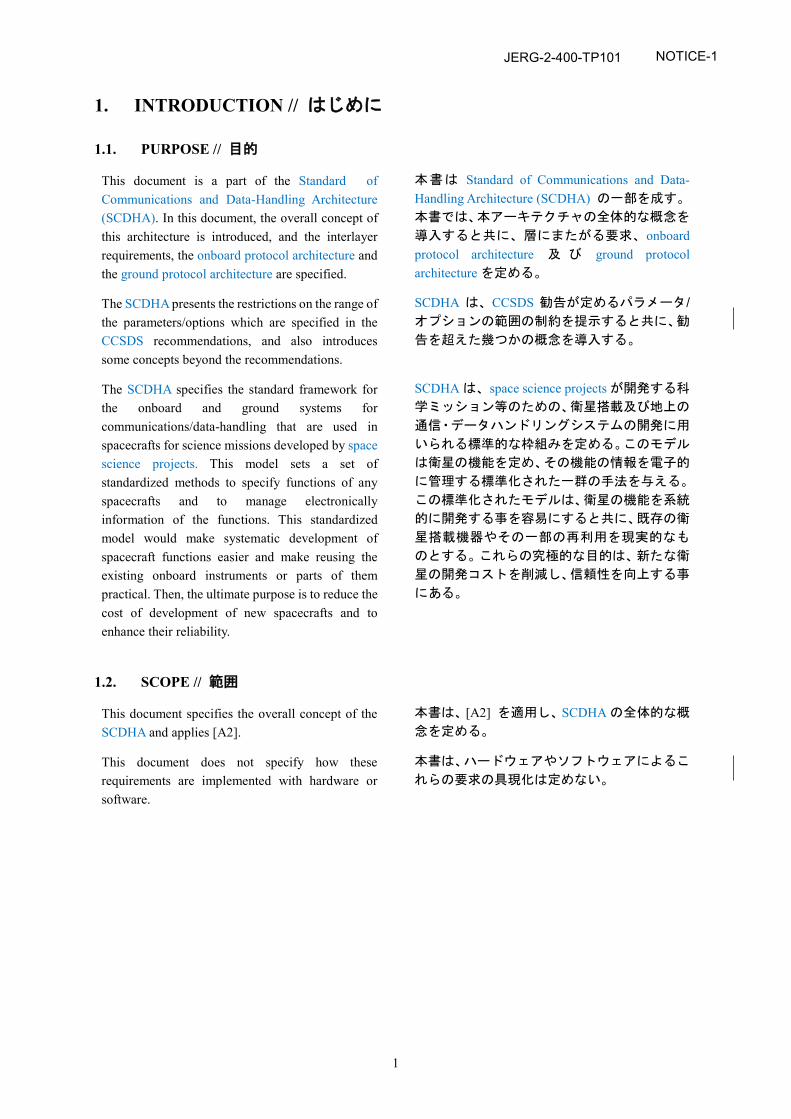
This document is a part of the Standard of Communications and Data-Handling Architecture (SCDHA). In this document, the overall concept of this architecture is introduced, and the interlayer requirements, the onboard protocol architecture and the ground protocol architecture are specified.
本書は Standard of Communications and Data-Handling Architecture (SCDHA) の一部を成す。
本書では、本アーキテクチャの全体的な概念を
導入すると共に、層にまたがる要求、onboard protocol architecture 及 び ground protocol architecture を定める。
The SCDHA presents the restrictions on the range of the parameters/options which are specified in the CCSDS recommendations, and also introduces some concepts beyond the recommendations.
SCDHA は、CCSDS 勧告が定めるパラメータ/オプションの範囲の制約を提示すると共に、勧
告を超えた幾つかの概念を導入する。
The SCDHA specifies the standard framework for the onboard and ground systems for communications/data-handling that are used in spacecrafts for science missions developed by space science projects. This model sets a set of standardized methods to specify functions of any spacecrafts and to manage electronically information of the functions. This standardized model would make systematic development of spacecraft functions easier and make reusing the existing onboard instruments or parts of them practical. Then, the ultimate purpose is to reduce the cost of development of new spacecrafts and to enhance their reliability.
SCDHA は、space science projects が開発する科
学ミッション等のための、衛星搭載及び地上の
通信・データハンドリングシステムの開発に用
いられる標準的な枠組みを定める。このモデル
は衛星の機能を定め、その機能の情報を電子的
に管理する標準化された一群の手法を与える。
この標準化されたモデルは、衛星の機能を系統
的に開発する事を容易にすると共に、既存の衛
星搭載機器やその一部の再利用を現実的なも
のとする。これらの究極的な目的は、新たな衛
星の開発コストを削減し、信頼性を向上する事
にある。
1.2. SCOPE // 範囲
This document specifies the overall concept of the SCDHA and applies [A2].
本書は、[A2] を適用し、SCDHA の全体的な概
念を定める。
This document does not specify how these requirements are implemented with hardware or software.
本書は、ハードウェアやソフトウェアによるこ
れらの要求の具現化は定めない。
NOTICE-1
JERG-2-400-TP101
2
1.3. APPLICABILITY // 適用先
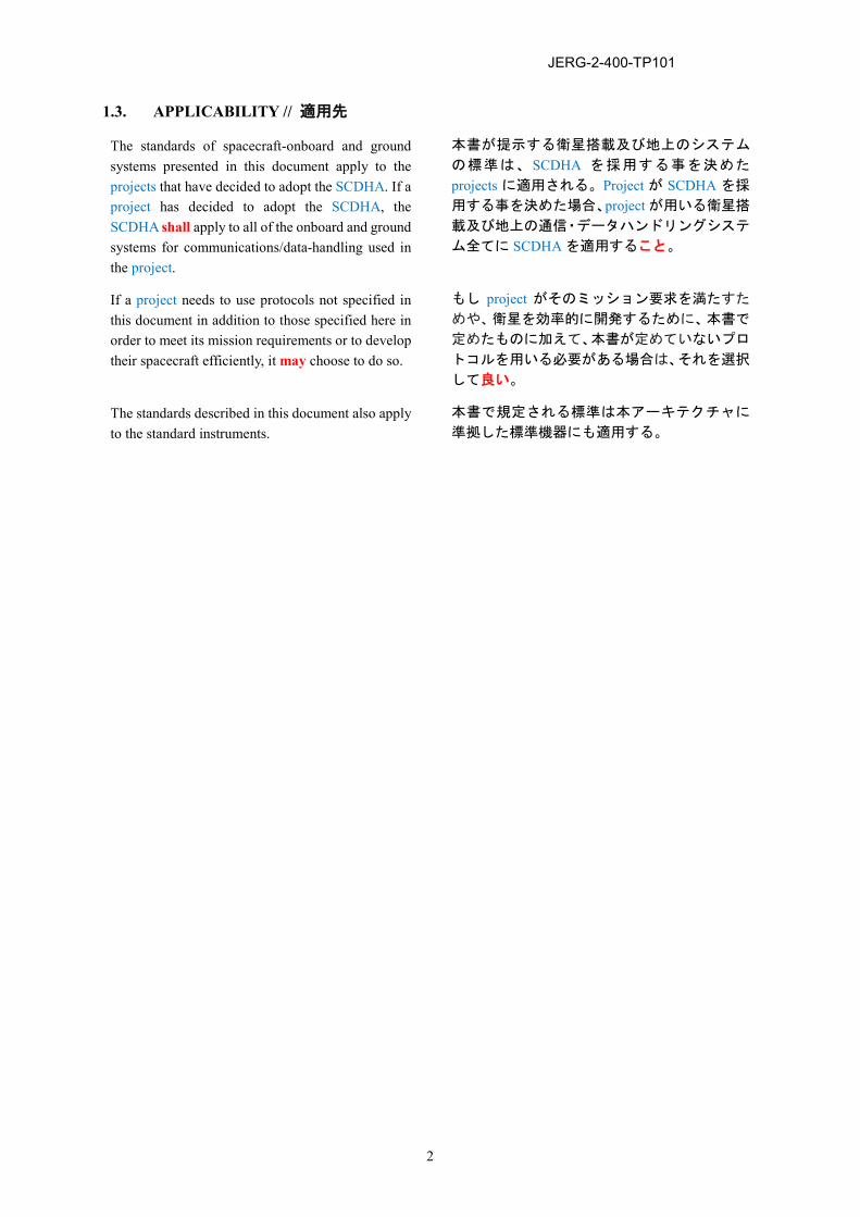
The standards of spacecraft-onboard and ground systems presented in this document apply to the projects that have decided to adopt the SCDHA. If a project has decided to adopt the SCDHA, the SCDHA shall apply to all of the onboard and ground systems for communications/data-handling used in the project.
本書が提示する衛星搭載及び地上のシステム
の標準は、SCDHA を採用する事を決めた
projects に適用される。Project が SCDHA を採
用する事を決めた場合、project が用いる衛星搭
載及び地上の通信・データハンドリングシステ
ム全てに SCDHA を適用すること。
If a project needs to use protocols not specified in this document in addition to those specified here in order to meet its mission requirements or to develop their spacecraft efficiently, it may choose to do so.
もし project がそのミッション要求を満たすた
めや、衛星を効率的に開発するために、本書で
定めたものに加えて、本書が定めていないプロ
トコルを用いる必要がある場合は、それを選択
して良い。
The standards described in this document also apply to the standard instruments.
本書で規定される標準は本アーキテクチャに
準拠した標準機器にも適用する。
JERG-2-400-TP101
3
1.4. REFERENCES // 関連文書
1.4.1. Normative References // 引用文書
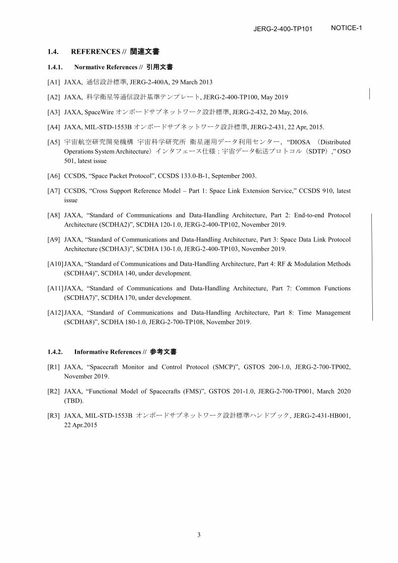
[A1] JAXA, 通信設計標準, JERG-2-400A, 29 March 2013
[A2] JAXA, 科学衛星等通信設計基準テンプレート, JERG-2-400-TP100, May 2019
[A3] JAXA, SpaceWire オンボードサブネットワーク設計標準, JERG-2-432, 20 May, 2016.
[A4] JAXA, MIL-STD-1553B オンボードサブネットワーク設計標準, JERG-2-431, 22 Apr, 2015.
[A5] 宇宙航空研究開発機構 宇宙科学研究所 衛星運用データ利用センター,“DIOSA (Distributed Operations System Architecture)インタフェース仕様:宇宙データ転送プロトコル(SDTP),” OSO 501, latest issue
[A6] CCSDS, “Space Packet Protocol”, CCSDS 133.0-B-1, September 2003.
[A7] CCSDS, “Cross Support Reference Model – Part 1: Space Link Extension Service,” CCSDS 910, latest issue
[A8] JAXA, “Standard of Communications and Data-Handling Architecture, Part 2: End-to-end Protocol Architecture (SCDHA2)”, SCDHA 120-1.0, JERG-2-400-TP102, November 2019.
[A9] JAXA, “Standard of Communications and Data-Handling Architecture, Part 3: Space Data Link Protocol Architecture (SCDHA3)”, SCDHA 130-1.0, JERG-2-400-TP103, November 2019.
[A10] JAXA, “Standard of Communications and Data-Handling Architecture, Part 4: RF & Modulation Methods (SCDHA4)”, SCDHA 140, under development.
[A11] JAXA, “Standard of Communications and Data-Handling Architecture, Part 7: Common Functions (SCDHA7)”, SCDHA 170, under development.
[A12] JAXA, “Standard of Communications and Data-Handling Architecture, Part 8: Time Management (SCDHA8)”, SCDHA 180-1.0, JERG-2-700-TP108, November 2019.
1.4.2. Informative References // 参考文書
[R1] JAXA, “Spacecraft Monitor and Control Protocol (SMCP)”, GSTOS 200-1.0, JERG-2-700-TP002, November 2019.
[R2] JAXA, “Functional Model of Spacecrafts (FMS)”, GSTOS 201-1.0, JERG-2-700-TP001, March 2020 (TBD).
[R3] JAXA, MIL-STD-1553B オンボードサブネットワーク設計標準ハンドブック, JERG-2-431-HB001, 22 Apr.2015
NOTICE-1
JERG-2-400-TP101
4
1.5. STRUCTURE OF THIS DOCUMENT // 文書構成
This document is organized as follows. 本書は次の通り構成する。
Chapter 1 (this chapter) states the purpose, scope, and applicability of the document, and lists the references, definitions, and notations used throughout the document.
1 章(本章)は、文書の目的、範囲及び適用先、
並びを述べると共に、本書で用いる関連文書、
定義、及び表記法を示す。
Chapter 2 presents an overview of the architecture. 2 章は、本アーキテクチャを概説する。
Chapter 3 specifies the requirements of this architecture.
3 章は、本アーキテクチャの要求事項を定める。
Appendix A lists the acronyms used in this document.
Appendix A は、本書で用いる略語を示す。
Appendix B shows the traceability between sections in this document and those in [A1].
Appendix B は、本書の各項と [A1] の各項のト
レーサビリティを示す。
JERG-2-400-TP101
5
1.6. DEFINITIONS AND NOTATIONS // 定義及び表記法
1.6.1. Terms defined in the Spacecraft Monitor and Control Protocol Spacecraft Monitor and Control Protocol で定義される用語
This document adopts the following terms defined in the Spacecraft Monitor and Control Protocol (SMCP) [R1]:
本書では、Spacecraft Monitor and Control Protocol (SMCP) [R1] で定義される次の用語を採用す
る。
Controller,
Monitor, and
Target.
Controller
Monitor
Target
JERG-2-400-TP101
6
1.6.2. Terms defined in this document // 本書で定義される用語
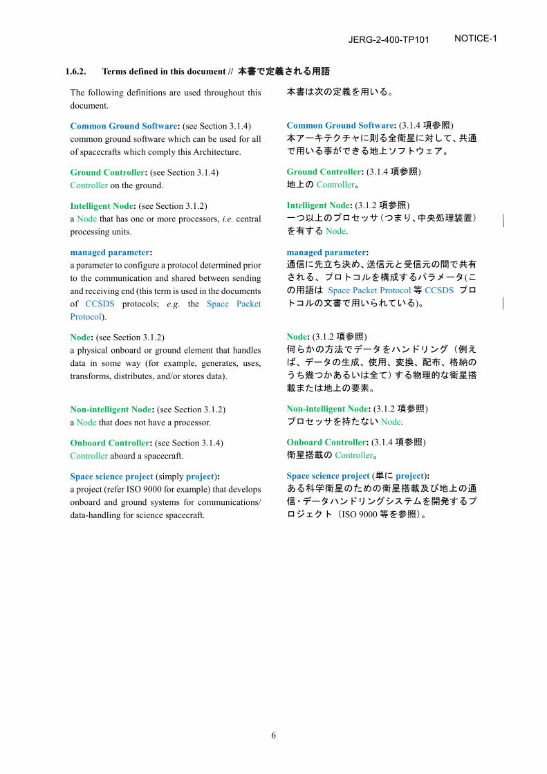
The following definitions are used throughout this document.
本書は次の定義を用いる。
Common Ground Software: (see Section 3.1.4) common ground software which can be used for all of spacecrafts which comply this Architecture.
Common Ground Software: (3.1.4 項参照) 本アーキテクチャに則る全衛星に対して、共通
で用いる事ができる地上ソフトウェア。
Ground Controller: (see Section 3.1.4) Controller on the ground.
Ground Controller: (3.1.4 項参照) 地上の Controller。
Intelligent Node: (see Section 3.1.2) a Node that has one or more processors, i.e. central processing units.
Intelligent Node: (3.1.2 項参照) 一つ以上のプロセッサ(つまり、中央処理装置)
を有する Node.
managed parameter: a parameter to configure a protocol determined prior to the communication and shared between sending and receiving end (this term is used in the documents of CCSDS protocols; e.g. the Space Packet Protocol).
managed parameter: 通信に先立ち決め、送信元と受信元の間で共有
される、プロトコルを構成するパラメータ(この用語は Space Packet Protocol 等 CCSDS プロ
トコルの文書で用いられている)。
Node: (see Section 3.1.2) a physical onboard or ground element that handles data in some way (for example, generates, uses, transforms, distributes, and/or stores data).
Node: (3.1.2 項参照) 何らかの方法でデータをハンドリング(例え
ば、データの生成、使用、変換、配布、格納の
うち幾つかあるいは全て)する物理的な衛星搭
載または地上の要素。
Non-intelligent Node: (see Section 3.1.2) a Node that does not have a processor.
Non-intelligent Node: (3.1.2 項参照) プロセッサを持たない Node.
Onboard Controller: (see Section 3.1.4) Controller aboard a spacecraft.
Onboard Controller: (3.1.4 項参照) 衛星搭載の Controller。
Space science project (simply project): a project (refer ISO 9000 for example) that develops onboard and ground systems for communications/ data-handling for science spacecraft.
Space science project (単に project): ある科学衛星のための衛星搭載及び地上の通
信・データハンドリングシステムを開発するプ
ロジェクト(ISO 9000 等を参照)。
NOTICE-1
JERG-2-400-TP101
7
1.6.3. Notations // 表記
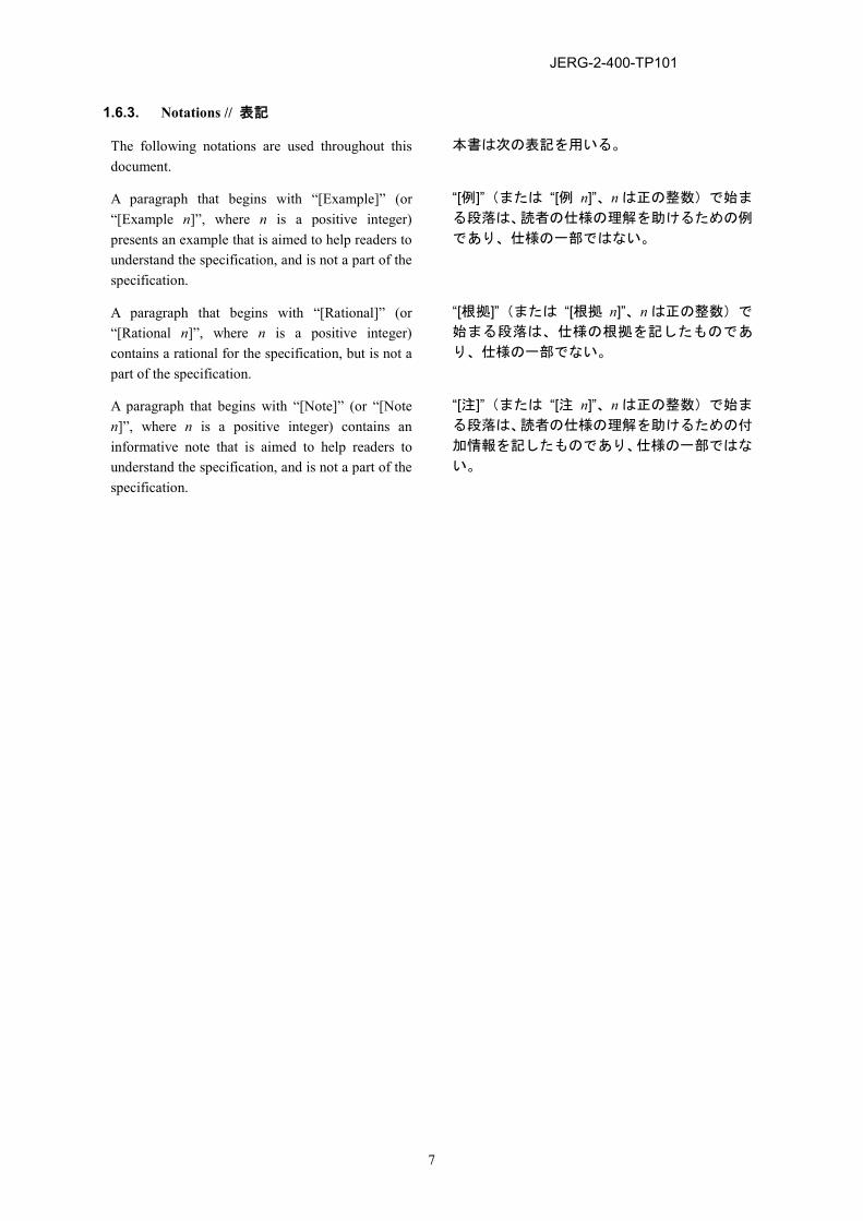
The following notations are used throughout this document.
本書は次の表記を用いる。
A paragraph that begins with “[Example]” (or “[Example n]”, where n is a positive integer) presents an example that is aimed to help readers to understand the specification, and is not a part of the specification.
“[例]”(または “[例 n]”、n は正の整数)で始ま
る段落は、読者の仕様の理解を助けるための例
であり、仕様の一部ではない。
A paragraph that begins with “[Rational]” (or “[Rational n]”, where n is a positive integer) contains a rational for the specification, but is not a part of the specification.
“[根拠]”(または “[根拠 n]”、n は正の整数)で
始まる段落は、仕様の根拠を記したものであ
り、仕様の一部でない。
A paragraph that begins with “[Note]” (or “[Note n]”, where n is a positive integer) contains an informative note that is aimed to help readers to understand the specification, and is not a part of the specification.
“[注]”(または “[注 n]”、n は正の整数)で始ま
る段落は、読者の仕様の理解を助けるための付
加情報を記したものであり、仕様の一部ではな
い。
JERG-2-400-TP101
8
1.7. VERBAL FORMS // 表現形式
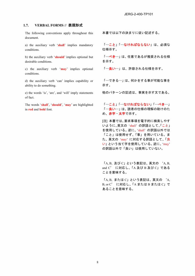
The following conventions apply throughout this document.
本書では以下の決まりに従い記述する。
a) the auxiliary verb ‘shall’ implies mandatory conditions.
「…こと」「…なければならない」は、必須な
仕様示す。
b) the auxiliary verb ‘should’ implies optional but desirable conditions.
「…べき…」は、任意であるが推奨される仕様
を示す。
c) the auxiliary verb ‘may’ implies optional conditions.
「…良い…」は、許容される仕様を示す。
d) the auxiliary verb ‘can’ implies capability or ability to do something.
「…できる…」は、何かをする事が可能な事を
示す。
e) the words ‘is’, ‘are’, and ‘will’ imply statements of fact.
他のパターンの記述は、事実を示す文である。
The words ‘shall’, ‘should’, ‘may’ are highlighted in red and bold font.
「…こと」「…なければならない」「…べき…」
「…良い…」は、読者の仕様の理解の助けのた
め、赤字・太字で示す。
[注] 本書では、要求事項を電子的に検索しやす
いように、英文の ‘shall’ の訳語として、「こと」
を使用している。逆に、‘shall’ の訳語以外では
「こと」は使用せず、「事」を用いている。ま
た、英文の ‘may’ に対応する訳語として、「良
い」という当て字を使用している。逆に、‘may’ の訳語以外で「良い」は使用していない。
「A, B, 及び C」という表記は、英文の ‘A, B, and C’ に対応し、「A 及び B 及び C」である
ことを意味する。
「A, B, または C」という表記は、英文の ‘A, B, or C’ に対応し、「A または B または C」で
あることを意味する。
JERG-2-400-TP101
9
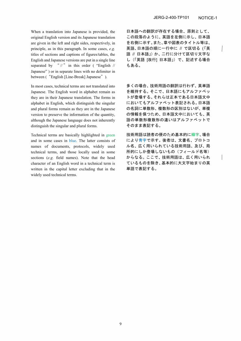
When a translation into Japanese is provided, the original English version and its Japanese translation are given in the left and right sides, respectively, in principle, as in this paragraph. In some cases, e.g. titles of sections and captions of figures/tables, the English and Japanese versions are put in a single line separated by “ // ” in this order ( “English // Japanese” ) or in separate lines with no delimiter in between (“English [Line-Break] Japanese”).
日本語への翻訳が存在する場合、原則として、
この段落のように、英語を左側に示し、日本語
を右側に示す。また、章や図表のタイトル等は、
英語、日本語の順に一行中に // で区切る (「英
語 // 日本語」)か、二行に分けて区切り文字な
し(「英語 [改行] 日本語」)で、記述する場合
もある。
In most cases, technical terms are not translated into Japanese. The English word in alphabet remain as they are in their Japanese translation. The forms in alphabet in English, which distinguish the singular and plural forms remain as they are in the Japanese version to preserve the information of the quantity, although the Japanese language does not inherently distinguish the singular and plural forms.
多くの場合、技術用語の翻訳は行わず、英単語
を維持する。そこで、日本語にもアルファベッ
トが登場する。それらは正本である日本語文中
においてもアルファベット表記される。日本語
の名詞に単数形、複数形の区別はないが、単複
の情報を保つため、日本語文中においても、英
語の単数形複数形の違いはアルファベットで
そのまま表記する。
Technical terms are basically highlighted in green and in some cases in blue. The latter consists of names of documents, protocols, widely used technical terms, and those locally used in some sections (e.g. field names). Note that the head character of an English word in a technical term is written in the capital letter excluding that in the widely used technical terms.
技術用語は読者の便のため基本的に緑字、場合
により青字で示す。後者は、文書名、プロトコ
ル名、広く用いられている技術用語、及び、局
所的にしか登場しないもの(フィールド名等)
からなる。ここで、技術用語は、広く用いられ
ているものを除き、基本的に大文字始まりの英
単語で表記する。
NOTICE-1
JERG-2-400-TP101
10
2. OVERVIEW // 概要
2.1. GENERAL // 一般
This chapter provides an overview of the Standard of Communications and Data-Handling Architecture (SCDHA).
本章では、Standard of Communications and Data-Handling Architecture (SCDHA) の概要を示す。
2.2. OVERALL ARCHITECTURE // 全体のアーキテクチャ
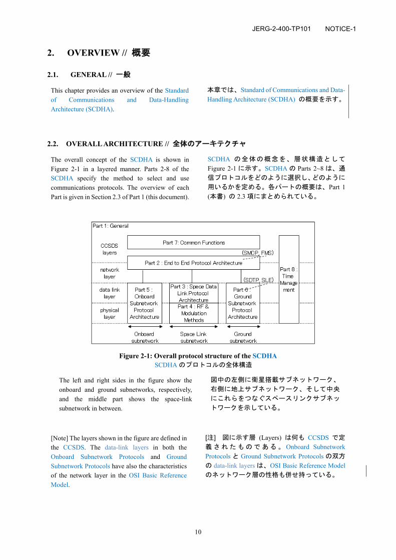
The overall concept of the SCDHA is shown in Figure 2-1 in a layered manner. Parts 2-8 of the SCDHA specify the method to select and use communications protocols. The overview of each Part is given in Section 2.3 of Part 1 (this document).
SCDHA の全体の概念を、層状構造として
Figure 2-1 に示す。SCDHA の Parts 2~8 は、通
信プロトコルをどのように選択し、どのように
用いるかを定める。各パートの概要は、Part 1 (本書) の 2.3 項にまとめられている。
Figure 2-1: Overall protocol structure of the SCDHA SCDHA のプロトコルの全体構造
The left and right sides in the figure show the onboard and ground subnetworks, respectively, and the middle part shows the space-link subnetwork in between.
図中の左側に衛星搭載サブネットワーク、
右側に地上サブネットワーク、そして中央
にこれらをつなぐスペースリンクサブネッ
トワークを示している。
[Note] The layers shown in the figure are defined in the CCSDS. The data-link layers in both the Onboard Subnetwork Protocols and Ground Subnetwork Protocols have also the characteristics of the network layer in the OSI Basic Reference Model.
[注] 図に示す層 (Layers) は何も CCSDS で定
義されたものである。 Onboard Subnetwork Protocols と Ground Subnetwork Protocols の双方
の data-link layers は、OSI Basic Reference Modelのネットワーク層の性格も併せ持っている。
NOTICE-1
JERG-2-400-TP101
11
2.3. PARTS OF THE SCDHA // SCDHA の PARTS
The SCDHA specifies the architecture with layer structures. The interlayer requirements are specified in Section 3.1 of this document (Part 1) except for the Time Management, which is specified in Part 8.
SCDHA は、アーキテクチャを層構造で定める。
層をまたがる要求は、Part 8 で定める Time Management を除き、本書 (Part 1) の 3.1 項に定
める。
An architecture generally specifies the methods to construct complex systems out of what kinds of elements for what purposes. In this architecture, onboard and ground systems for communications/ data-handling for a project are constructed by connecting Nodes (physical elements) with the standard communications protocols. Each Node performs functions for generating, processing and/or delivering data.
アーキテクチャは、一般に、複雑なシステムを、
どのような目的に対して、どのような要素を用
いて構築するかを定める。本アーキテクチャで
は、project の衛星搭載及び地上の通信・データ
ハンドリングシステムは、標準通信プロトコル
で Nodes(物理要素)を接続する事で構成する。
Node は、データ生成、処理、配信のうち幾つか
または全てを実行する機能を有する。
Part 2, End-to-End Protocol Architecture [A8], specifies the standard framework for the specifications about the end-to-end protocols for communications between onboard and ground End Nodes and among onboard End Nodes. The protocols specified in Part 2 are also used between onboard Nodes if certain onboard Nodes monitor and/or control other onboard Nodes. These protocols are used at the top level of the protocols specified in Parts 3-6.
Part 2: End-to-End Protocol Architecture [A8] は、
衛星搭載及び地上の End Nodes 間の通信、並び
に衛星搭載 End Nodes 間の通信、のための end-to-end protocols の仕様の、標準的な枠組みを定め
る。Part2 で定めるプロトコルは、ある衛星搭載
Nodes が、他の衛星搭載 Nodes を、監視、制御の
うち一方または両方をする場合には、衛星搭載
Nodes 間でも用いる。これらのプロトコルは、
Parts 3 ~ 6 で定めるプロトコルの最上位で用い
る。
Spacecraft Monitor and Control Protocol (SMCP) [R1] is applied to Part 2 for monitoring and controlling onboard Nodes from a spacecraft operations system located either on the ground or onboard the spacecraft. The SMCP assumes that the functions of components in a spacecraft are specified according to the Functional Model of Spacecrafts (FMS) [R2].
Part 2 には、衛星搭載 Nodes を、地上またはその
衛星搭載の衛星運用システムから監視制御する
ために、Spacecraft Monitor and Control Protocol (SMCP) [R1] を適用する。SMCP は、衛星の機器
の機能が、Functional Model of Spacecrafts (FMS) [R2] に従って定められている事を前提として
いる。
Part 3, Space Data Link Protocol Architecture [A9], specifies the standard framework for the specifications about the space data link protocols used for communications on the RF links that connect a spacecraft and the ground.
Part 3: Space Data Link Protocol Architecture [A9] は、衛星と地上を結ぶ RF リンク通信に用いる
space data link protocols の仕様の、標準的な枠組
みを定める。
Part 4, RF & Modulation Methods [A10], specifies the standard framework for the specifications about the radio frequency and modulation methods used for communications on the RF links that connect a spacecraft and the ground.
Part 4: RF & Modulation Methods [A10] は、衛星
と地上を結ぶ RF リンク通信に用いる無線周波
数と変調方式の仕様の、標準的な枠組みを定め
る。
JERG-2-400-TP101
12
Part 5 (Onboard Subnetwork Protocol Architecture described in Section 3.5 of this document) specifies the standard framework for the specifications about the onboard subnetwork protocols used for communications among onboard Nodes.
本書の 3.5 項に記す Part 5: Onboard Subnetwork Protocol Architecture は、衛星搭載 Nodes 間の通
信に用いる、onboard subnetwork protocols の仕様
の、標準的な枠組みを定める。
Part 6 (Ground Subnetwork Protocol Architecture described in Section 3.3 of this document) specifies the standard framework for the specifications about the ground subnetwork protocols used for communications among ground Nodes.
本書の 3.3 項に記す Part 6: Ground Subnetwork Protocol Architecture は、地上 Nodes 間の通信に
用いる、ground subnetwork protocols の仕様の、標
準的な枠組みを定める。
The Spacecraft Data Transfer Protocol (SDTP) [A5] and the Space Link Extension (SLE) [A7] are applied to Part 6 for the ground subnetwork protocols used for the communications among ground Nodes.
Part 6 には、地上 Nodes 間の通信に用いる ground subnetwork protocols として、 Spacecraft Data Transfer Protocol (SDTP) [A5] 及び Space Link Extension (SLE) [A7] を適用する。
[Note] To Part 6, the space data link protocols, which are applied mainly to Part3, are also used.
[注] Part6 では、主に Part3 に適用されるもので
ある space data link protocols も用いる。
Part 7 (Common functions [A11]) specifies the common functions for a spacecraft and its spacecraft operation systems.
Part 7: Common functions [A11] は、衛星及びその
衛星運用システムでの共通の機能を定める。
Part 8 (Time Management [A12]) specifies the handling of time for a spacecraft and its spacecraft operation systems, whose requirements cover multiple layers.
Part 8: Time Management [A12] は、衛星及びその
衛星運用システムにおける時刻の取り扱いを定
める。その要求は、複数の層にまたがる。
NOTICE-1
JERG-2-400-TP101
13
3. REQUIREMENTS // 要求事項
3.1. INTERLAYER REQUIREMENTS // 複数の層にまたがる要求
3.1.1. General // 一般
The Standard of Communications and Data-Handling Architecture (SCDHA) specifies the architecture with layer structures. This section specifies the interlayer requirements in the SCDHA except for the Time Management, which is specified in Part 8.
Standard of Communications and Data-Handling Architecture (SCDHA) は、アーキテクチャを層
構造で定める。本項は、SCDHA における層に
またがる要求のうち、Part 8 で定める Time Management を除いたものを定める。
This architecture specifies (1) the basic elements used in the onboard and ground systems for communications/data-handling, and (2) how the onboard and ground systems for communications/data-handling are constructed out of the basic elements.
本アーキテクチャは、(1) 衛星搭載及び地上の
通信・データハンドリングシステムで用いる基
本要素、並びに、 (2) その基本要素を使い衛星
搭載及び地上の通信・データハンドリングシス
テムをどのように構築するか、を定める。
3.1.2. Basic Elements // 基本要素
This architecture specifies three kinds of basic elements: Nodes (physical elements), Functions (functional elements), and communications protocols.
本アーキテクチャは、Nodes(物理要素)、
Functions(機能要素)、及び通信プロトコルの三
種類の基本要素を定める。
The onboard and ground systems for communications/data-handling of any project are composed of Nodes. A Node is defined as a physical (onboard or ground) element that handles data in some way. Nodes generate, use, transform, distribute, and/or store data (telecommands, telemetry and/or other kinds of data). The elements that do not handle data in any way (for example, structural elements) are not considered as Nodes in this architecture.
何れの project の衛星搭載及び地上の通信・デ
ータハンドリングシステムも、Nodes で構成さ
れる。Node は、何らかの方法でデータを扱う
物理的(衛星搭載または地上)要素と定義する。
Nodes は、データ(テレコマンド、テレメトリ、
他の種類のデータのうち幾つかあるいは全て)
を生成、使用、変換、配布、格納のうち幾つか
あるいは全てを行う。いかなる方法でもデータ
を扱わない要素(構造的要素等)は、本アーキ
テクチャでは Nodes とは見なさない。
There are two types of Nodes: Intelligent Node and Non-intelligent Node. The Intelligent Node is defined as a Node that has one or more processors. The Non-intelligent Node is defined as a Node that does not have a processor.
Nodes には、Intelligent Node と Non-intelligent Node の二種類がある。Intelligent Node は、一つ
以上のプロセッサを有する Node と定義する。
Non-intelligent Node は、プロセッサを持たない
Node と定義する。
JERG-2-400-TP101
14
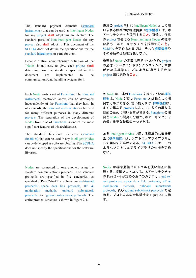
The standard physical elements (standard instruments) that can be used as Intelligent Nodes for any project shall adopt this architecture. The standard parts of Non-intelligent Nodes for any project also shall adopt it. This document of the SCDHA does not define the specifications for the standard instruments or parts for them.
任意の project 向けに Intelligent Nodes として用
いられる標準的な物理要素(標準機器)は、本
アーキテクチャを採用すること。同様に、任意
の project で使える Non-intelligent Nodes の標準
部品も、本アーキテクチャを採用すること。
SCDHA を定める本書では、それら標準機器や
その部品の仕様を定義しない。
Because a strict comprehensive definition of the “Node” is not easy to give, each project shall determine how the standards specified in this document are implemented to the communications/data-handling systems for it.
厳密な「Node」の定義は容易でないため、projectの通信・データハンドリングシステムに、本書
が定める標準を、どのように適用するかは
project 毎に決めること。
Each Node hosts a set of Functions. The standard instruments mentioned above can be developed independently of the Functions that they host. In other words, the standard instruments can be used for many different purposes in many different projects. The separation of the development of Nodes from that of Functions is one of the most significant features of this architecture.
各 Node は一連の Functions を持つ。上記の標準
機器は、Node が持つ Functions とは独立して開
発する事ができる。言い換えれば、標準機器は、
多くの異なる projects において、多くの異なる
目的のために用いる事ができる。Functions の開
発と Nodes の開発の分離が、本アーキテクチャ
の最も重要な特徴の一つである。
The standard functional elements (standard functions) that can be used in any Intelligent Nodes can be developed as software libraries. The SCDHA does not specify the specifications for the software libraries.
ある Intelligent Nodes で用いる標準的な機能要
素(標準機能)は、ソフトウェアライブラリと
して開発する事ができる。SCDHA では、この
ようなソフトウェアライブラリの仕様を定め
ない。
Nodes are connected to one another, using the standard communications protocols. The standard protocols are specified in five categories, as specified in Parts 2-6 of this architecture: end-to-end protocols, space data link protocols, RF & modulation methods, onboard subnetwork protocols, and ground subnetwork protocols. The entire protocol structure is shown in Figure 2-1.
Nodes は標準通信プロトコルを使い相互に接
続する。標準プロトコルは、本アーキテクチャ
の Parts 2 ~ 6 が定める五つのカテゴリ;end-to-end protocols, space data link protocols, RF & modulation methods, onboard subnetwork protocols, 及び ground subnetwork protocols で定
める。プロトコルの全体構造を Figure 2-1 に示
す。
JERG-2-400-TP101
15
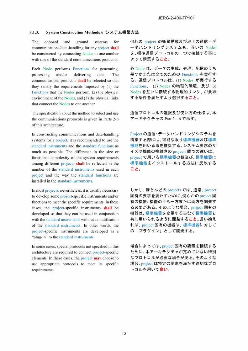
3.1.3. System Construction Methods // システム構築方法
The onboard and ground systems for communications/data-handling for any project shall be constructed by connecting Nodes to one another with one of the standard communications protocols.
何れの project の衛星搭載及び地上の通信・デ
ータハンドリングシステムも、互いの Nodesを、標準通信プロトコルの一つで接続する事に
よって構築すること。
Each Node performs Functions for generating, processing and/or delivering data. The communications protocols shall be selected so that they satisfy the requirements imposed by (1) the Functions that the Nodes perform, (2) the physical environment of the Nodes, and (3) the physical links that connect the Nodes to one another.
各 Node は、データの生成、処理、配信のうち
幾つかまたは全てのための Functions を実行す
る。通信プロトコルは、(1) Nodes が実行する
Functions、 (2) Nodes の物理的環境、及び (3) Nodes を互いに接続する物理的リンク、が要求
する条件を満たすよう選択すること。
The specification about the method to select and use the communications protocols is given in Parts 2-6 of this architecture.
通信プロトコルの選択及び使い方の仕様は、本
アーキテクチャの Part 2 ~ 6 で示す。
In constructing communications and data-handling systems for a project, it is recommended to use the standard instruments and the standard functions as much as possible. The difference in the size or functional complexity of the system requirements among different projects shall be reflected in the number of the standard instruments used in each project and the way the standard functions are installed in the standard instruments.
Project の通信・データハンドリングシステムを
構築する際には、可能な限り標準機器及び標準
機能を用いる事を推奨する。システム要求のサ
イズや機能の複雑さの projects 間での違いは、
project で用いる標準機器の数及び、標準機器に
標準機能をインストールする方法に反映する
こと。
In most projects, nevertheless, it is usually necessary to develop some project-specific instruments and/or functions to meet the specific requirements. In these cases, the project-specific instruments shall be developed so that they can be used in conjunction with the standard instruments without a modification of the standard instruments. In other words, the project-specific instruments are developed as a “plug-in” to the standard instruments.
しかし、ほとんどの projects では、通常、project固有の要求を満たすために、何らかの project固有の機器、機能のうち一方または両方を開発す
る必要がある。そのような場合、project 固有の
機器は、標準機器を変更する事なく標準機器と
共に用いられるように開発すること。言い換え
れば、project 固有の機器は、標準機器に対して
の「プラグイン」として開発する。
In some cases, special protocols not specified in this architecture are required to connect project-specific elements. In these cases, the project may choose to use appropriate protocols to meet its specific requirements.
場合によっては、project 固有の要素を接続する
ために、本アーキテクチャが定めていない特別
なプロトコルが必要な場合がある。そのような
場合、project は特定の要求を満たす適切なプロ
トコルを用いて良い。
JERG-2-400-TP101
16
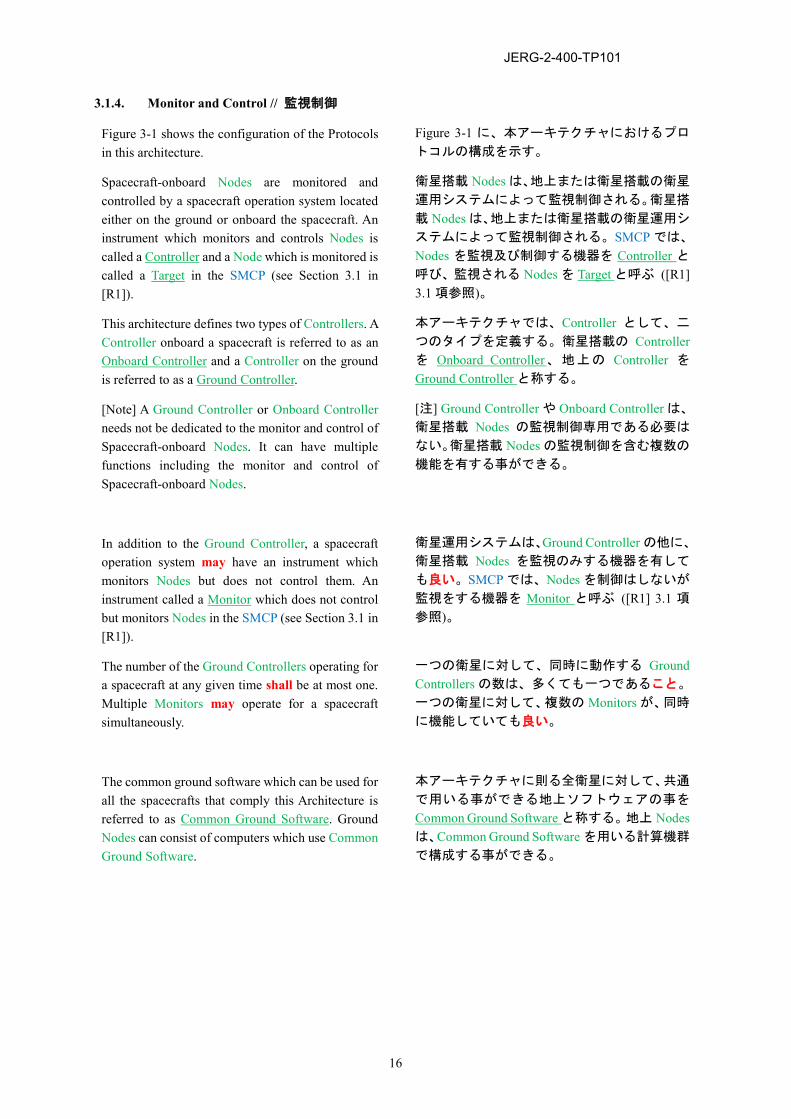
3.1.4. Monitor and Control // 監視制御
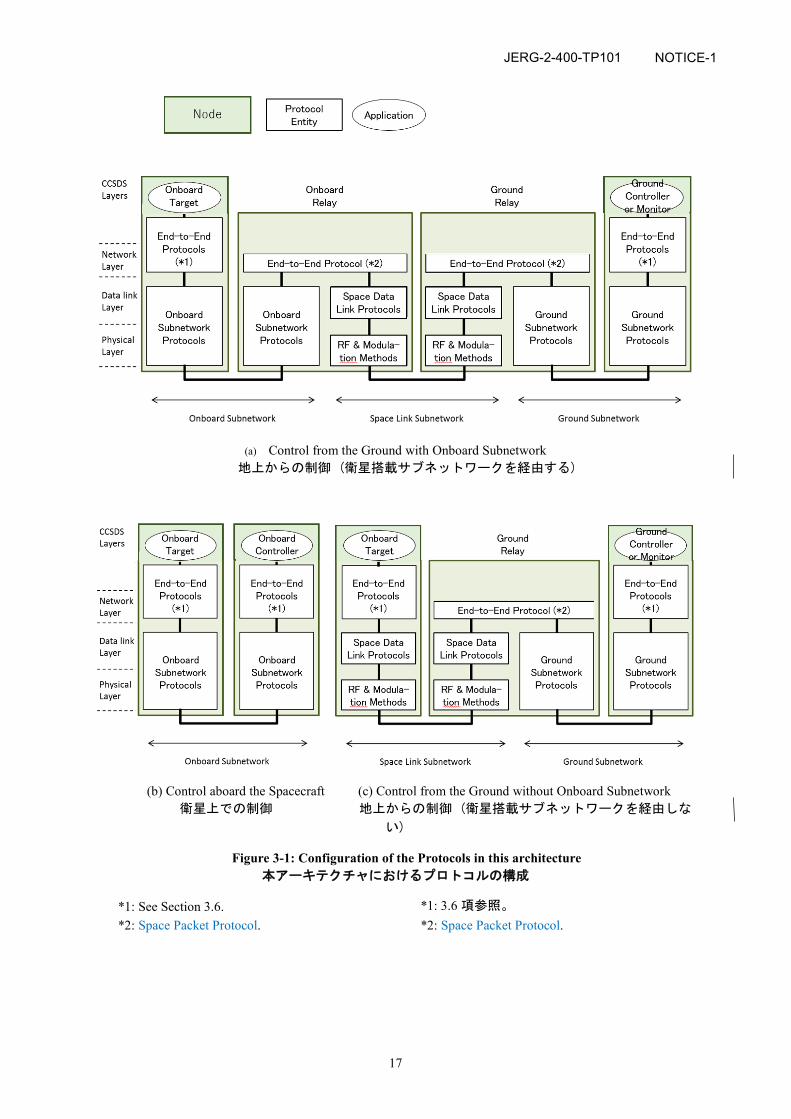
Figure 3-1 shows the configuration of the Protocols in this architecture.
Figure 3-1 に、本アーキテクチャにおけるプロ
トコルの構成を示す。
Spacecraft-onboard Nodes are monitored and controlled by a spacecraft operation system located either on the ground or onboard the spacecraft. An instrument which monitors and controls Nodes is called a Controller and a Node which is monitored is called a Target in the SMCP (see Section 3.1 in [R1]).
衛星搭載 Nodes は、地上または衛星搭載の衛星
運用システムによって監視制御される。衛星搭
載 Nodes は、地上または衛星搭載の衛星運用シ
ステムによって監視制御される。SMCP では、
Nodes を監視及び制御する機器を Controller と呼び、監視される Nodes を Target と呼ぶ ([R1] 3.1 項参照)。
This architecture defines two types of Controllers. A Controller onboard a spacecraft is referred to as an Onboard Controller and a Controller on the ground is referred to as a Ground Controller.
本アーキテクチャでは、Controller として、二
つのタイプを定義する。衛星搭載の Controllerを Onboard Controller、地上の Controller を
Ground Controller と称する。
[Note] A Ground Controller or Onboard Controller needs not be dedicated to the monitor and control of Spacecraft-onboard Nodes. It can have multiple functions including the monitor and control of Spacecraft-onboard Nodes.
[注] Ground Controller や Onboard Controller は、
衛星搭載 Nodes の監視制御専用である必要は
ない。衛星搭載 Nodes の監視制御を含む複数の
機能を有する事ができる。
In addition to the Ground Controller, a spacecraft operation system may have an instrument which monitors Nodes but does not control them. An instrument called a Monitor which does not control but monitors Nodes in the SMCP (see Section 3.1 in [R1]).
衛星運用システムは、Ground Controller の他に、
衛星搭載 Nodes を監視のみする機器を有して
も良い。SMCP では、Nodes を制御はしないが
監視をする機器を Monitor と呼ぶ ([R1] 3.1 項
参照)。
The number of the Ground Controllers operating for a spacecraft at any given time shall be at most one. Multiple Monitors may operate for a spacecraft simultaneously.
一つの衛星に対して、同時に動作する Ground Controllers の数は、多くても一つであること。
一つの衛星に対して、複数の Monitors が、同時
に機能していても良い。
The common ground software which can be used for all the spacecrafts that comply this Architecture is referred to as Common Ground Software. Ground Nodes can consist of computers which use Common Ground Software.
本アーキテクチャに則る全衛星に対して、共通
で用いる事ができる地上ソフトウェアの事を Common Ground Software と称する。地上 Nodesは、Common Ground Software を用いる計算機群
で構成する事ができる。
JERG-2-400-TP101
17
(a) Control from the Ground with Onboard Subnetwork 地上からの制御 (衛星搭載サブネットワークを経由する)
(b) Control aboard the Spacecraft (c) Control from the Ground without Onboard Subnetwork 衛星上での制御 地上からの制御 (衛星搭載サブネットワークを経由しな
い)
Figure 3-1: Configuration of the Protocols in this architecture 本アーキテクチャにおけるプロトコルの構成
*1: See Section 3.6. *2: Space Packet Protocol.
*1: 3.6 項参照。 *2: Space Packet Protocol.
NOTICE-1
JERG-2-400-TP101
18
3.2. STANDARD PROTOCOLS // 標準プロトコル
Section 5.2 of Design Standard Communications [A1] shall be applied to this architecture, unless otherwise specified in a project.
Project にて特に指定しない限り、本アーキテ
クチャでは、通信設計標準 [A1] の 5.2 項を
適用すること。
JERG-2-400-TP101
19
3.3. PART 6: GROUND SUBNETWORK PROTOCOL ARCHITECTURE
3.3.1. General // 一般
This section (Part 6: Ground Subnetwork Protocol Architecture) specifies the standard framework for the specifications about the ground subnetwork protocols used for the communications among ground Nodes.
本 項 (Part 6: Ground Subnetwork Protocol Architecture) は、地上 Nodes 間の通信に用いる
ground subnetwork protocols の仕様の標準的な
枠組みを定める。
3.3.2. Specification // 仕様
Section 5.3 (ground subnetwork protocol) of Design Standard Communication [A1] shall be applied to the ground subnetwork protocols. Note that the Space Data Transfer Protocol (SDTP) [A5] and the Space Link Extension (SLE) [A7] are adopted in the section.
Ground subnetwork protocols に、通信設計標準 [A1] の 5.3 項 (地上サブネットワークプロト
コル) を適用すること。なお同項では、Space Data Transfer Protocol (SDTP) [A5] 及び Space Link Extension (SLE) [A7] が採用されている。
JERG-2-400-TP101
20
3.4. PART 3: SPACE DATA LINK PROTOCOL ARCHITECTURE, PART 4: RF & MODULATION METHODS
Part 3 (Space Data Link Protocol Architecture [A9]) and Part 4 (RF & modulation method [A10]) shall be applied.
Part 3: Space Data Link Protocol Architecture [A9] 及び Part 4: RF & modulation method [A10] を適用す
ること。
JERG-2-400-TP101
21
3.5. PART 5: ONBOARD SUBNETWORK PROTOCOL ARCHITECTURE
3.5.1. General // 一般
This section (Part 5: Onboard Subnetwork Protocol Architecture) specifies the standard framework for the specifications about the onboard subnetwork protocols used for the communications among onboard Nodes.
本 項 (Part 5: Onboard Subnetwork Protocol Architecture) は、衛星搭載 Nodes 間の通信に用
いる onboard subnetwork protocols の仕様の標準
的な枠組みを定める。
3.5.2. Specification // 仕様
MIL-STD-1553B [A4] and/or SpaceWire [A3] shall be applied to the onboard subnetwork protocols.
Onboard subnetwork protocols に MIL-STD-1553B [A4], SpaceWire [A3] のうち一方または
両方を適用すること。
[A4] assumes transfer of the application data with the Space Packet protocol. If [A4] is adopted by a project and yet if some application data are transferred with a protocol that is not the Space Packet protocol, the project shall specify the standard of the transfer.
[A4] は Space Packet protocol によるアプリケー
ションデータの伝送を前提としている。Projectが [A4] を採用するが、ある種のアプリケーシ
ョンデータを Space Packet protocol 以外のプロ
トコルで伝送する場合、project はその伝送の標
準を定めること。
JERG-2-400-TP101
22
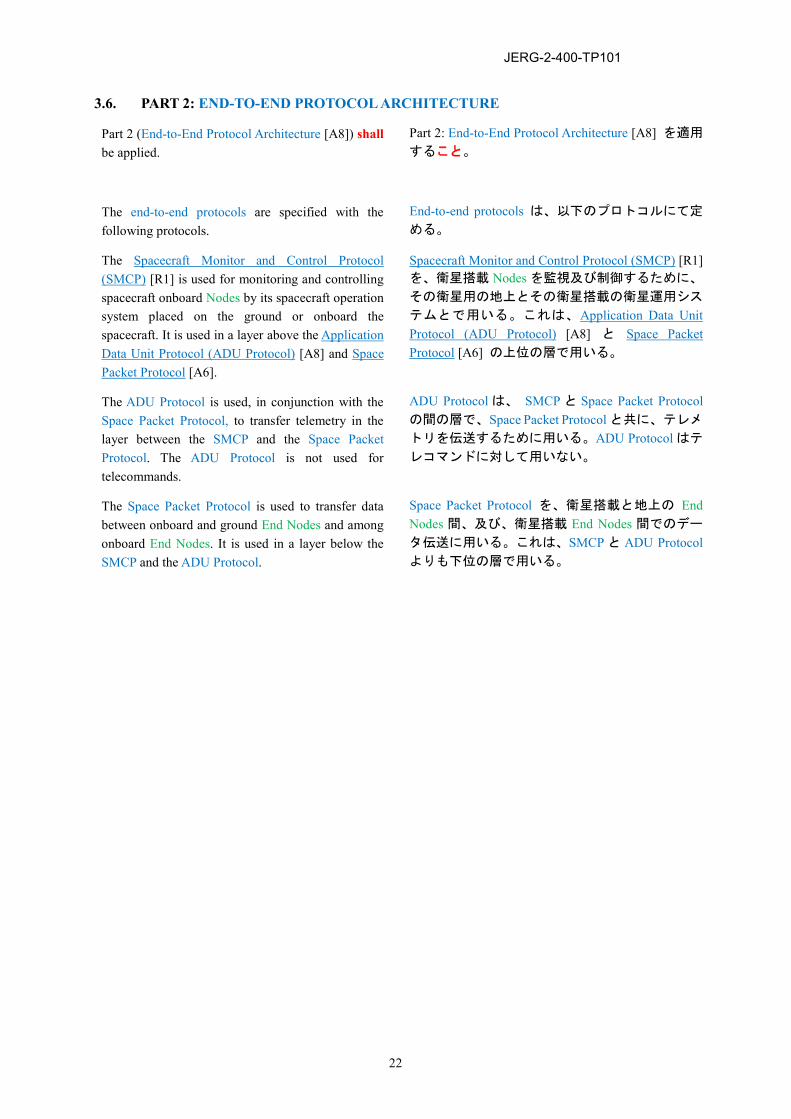
3.6. PART 2: END-TO-END PROTOCOL ARCHITECTURE
Part 2 (End-to-End Protocol Architecture [A8]) shall be applied.
Part 2: End-to-End Protocol Architecture [A8] を適用
すること。
The end-to-end protocols are specified with the following protocols.
End-to-end protocols は、以下のプロトコルにて定
める。
The Spacecraft Monitor and Control Protocol (SMCP) [R1] is used for monitoring and controlling spacecraft onboard Nodes by its spacecraft operation system placed on the ground or onboard the spacecraft. It is used in a layer above the Application Data Unit Protocol (ADU Protocol) [A8] and Space Packet Protocol [A6].
Spacecraft Monitor and Control Protocol (SMCP) [R1] を、衛星搭載 Nodes を監視及び制御するために、
その衛星用の地上とその衛星搭載の衛星運用シス
テムとで用いる。これは、Application Data Unit Protocol (ADU Protocol) [A8] と Space Packet Protocol [A6] の上位の層で用いる。
The ADU Protocol is used, in conjunction with the Space Packet Protocol, to transfer telemetry in the layer between the SMCP and the Space Packet Protocol. The ADU Protocol is not used for telecommands.
ADU Protocol は、 SMCP と Space Packet Protocolの間の層で、Space Packet Protocol と共に、テレメ
トリを伝送するために用いる。ADU Protocol はテ
レコマンドに対して用いない。
The Space Packet Protocol is used to transfer data between onboard and ground End Nodes and among onboard End Nodes. It is used in a layer below the SMCP and the ADU Protocol.
Space Packet Protocol を、衛星搭載と地上の End Nodes 間、及び、衛星搭載 End Nodes 間でのデー
タ伝送に用いる。これは、SMCP と ADU Protocolよりも下位の層で用いる。
JERG-2-400-TP101
23
APPENDIX A. ACRONYMS // 略語
This chapter lists the acronyms used in this document.
本章では、本書が用いる略語一覧を示す。
ADU Application Data Unit SCDHA Standard of Communications and Data-Handling Architecture SDTP Space Data Transfer Protocol SLE Space Link Extension SMCP Spacecraft Monitor and Control Protocol
JERG-2-400-TP101
24
APPENDIX B. TRACEABILITY // トレーサビリティ
This architecture applies [A2] which applies [A1]. Table B-1 gives traceability between sections in this document and those in [A1]. Section 3.n (.m) of this document corresponds to Section 5.n (.m) in [A1], where n and m are positive integer numbers. Note that the table of contents of [A2] and that of [A1] coincide.
本アーキテクチャは、[A1] を適用している
[A2] を適用している。Table B-1 に、本書の各
項の [A1] の各項に対するトレーサビリティ
を示す。本書の 3.n (.m)項は [A1] の 5.n (.m)項に対応する (ここで、n 及び m) は正の整数で
ある)。なお、[A2] の目次と [A1] の目次は一
致している。
JERG-2-400-TP101
25
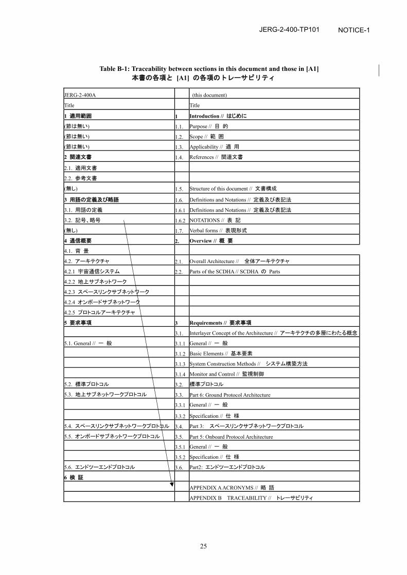
Table B-1: Traceability between sections in this document and those in [A1] 本書の各項と [A1] の各項のトレーサビリティ
JERG-2-400A (this document)
Title Title
1 適用範囲 1 Introduction // はじめに
(節は無い) 1.1. Purpose // 目 的
(節は無い) 1.2. Scope // 範 囲
(節は無い) 1.3. Applicability // 適 用
2 関連文書 1.4. References // 関連文書
2.1. 適用文書
2.2. 参考文書
(無し) 1.5. Structure of this document // 文書構成
3 用語の定義及び略語 1.6. Definitions and Notations // 定義及び表記法
3.1. 用語の定義 1.6.1 Definitions and Notations // 定義及び表記法
3.2. 記号、略号 1.6.2 NOTATIONS // 表 記
(無し) 1.7. Verbal forms // 表現形式
4 通信概要 2. Overview // 概 要
4.1. 背 景
4.2. アーキテクチャ 2.1. Overall Architecture // 全体アーキテクチャ
4.2.1 宇宙通信システム 2.2. Parts of the SCDHA // SCDHA の Parts
4.2.2 地上サブネットワーク
4.2.3 スペースリンクサブネットワーク
4.2.4 オンボードサブネットワーク
4.2.5 プロトコルアーキテクチャ
5 要求事項 3 Requirements // 要求事項
3.1. Interlayer Concept of the Architecture // アーキテクチの多層にわたる概念
5.1. General // 一 般 3.1.1 General // 一 般
3.1.2 Basic Elements // 基本要素
3.1.3 System Construction Methods // システム構築方法
3.1.4 Monitor and Control // 監視制御
5.2. 標準プロトコル 3.2. 標準プロトコル
5.3. 地上サブネットワークプロトコル 3.3. Part 6: Ground Protocol Architecture
3.3.1 General // 一 般
3.3.2 Specification // 仕 様
5.4. スペースリンクサブネットワークプロトコル 3.4. Part 3: スペースリンクサブネットワークプロトコル
5.5. オンボードサブネットワークプロトコル 3.5. Part 5: Onboard Protocol Architecture
3.5.1 General // 一 般
3.5.2 Specification // 仕 様
5.6. エンドツーエンドプロトコル 3.6. Part2: エンドツーエンドプロトコル
6 検 証
APPENDIX A ACRONYMS // 略 語
APPENDIX B TRACEABILITY // トレーサビリティ
NOTICE-1