Embed Size (px)
Citation preview

Published: October 04, 2011
r 2011 American Chemical Society 12809 dx.doi.org/10.1021/jp207918y | J. Phys. Chem. B 2011, 115, 12809–12815
ARTICLE
pubs.acs.org/JPCB
Effects of Tether Length on the Behavior of Amphiphilic Bent-CoreMolecules at Water SurfacesTimothy J. Smith,† Wilder Iglesias,‡ Sharon R. Stefanovic,§ Elizabeth K. Mann,§ Carsten Tschierske,||
Antal J�akli,‡ and Daniel J. Lacks*,†
†Chemical Engineering, Case Western Reserve University, Cleveland, Ohio 44106, United States‡Liquid Crystal Institute, Kent State University, Kent, Ohio 44242, United States§Physics Department, Kent State University, Kent, Ohio 44242, United States
)Institute of Organic Chemistry, Martin-Luther-University Halle-Wittenberg, Halle D06120, Germany
’ INTRODUCTION
Bent-core molecules exhibit a wide range of interesting pro-perties and potential applications. These molecules can formmany smectic phases, from B1�B8, which have prompted muchresearch on the structure and behavior of the phases.1,3 Bent-coremolecules behave as non-Newtonian fluids that can (in somecases) form fibers4 and have been used as side chains on polymersto form liquid crystal elastomers with rubber elasticity andsmectic ordering.5 The chirality6 and polar switching of bent-core liquid crystals give rise to ferroelectricity within somesmectic layers.7,8 In addition, optically active systems of bent-core liquid crystals can be controlled by electric fields.2 Applica-tions have not yet exploited the potential of ferroelectric phases,due in part to the difficulty of aligning the bulk liquid crystals.This article addresses issues involved with the development ofmethods to carry out this alignment.
A bulk liquid crystal can be aligned by surface layers that guidethe self-packing of the liquid crystal molecules at the interfaces,with this order transmitted from the interface into the bulk liquidcrystal. Alignment layers have been ineffective for bent-coreliquid crystals, probably because the usual alignment layers areincompatible with the shape and symmetry of the bent-coremolecules.9,10 For this reason, an alignment layer composed of
bent-core molecules may be more effective. In this direction, weshowed that a layer of bent-coremolecules, formed as a Langmuirmonolayer at the air/water interface and then transferred to aglass surface by Langmuir�Schaefer techniques, can align a bent-core nematic liquid crystal.11 While the monolayers of bent-coremolecules have been produced by several groups,12�18 thesemonolayers were unstable under compression11,15,19 and couldonly impart parallel alignment in the liquid crystal cell.11,20,21 Thereason for these limitations is that in these molecules the centralcore is hydrophilic, with hydrophobic pendent groups at bothends, which causes the molecules to lay horizontal on the watersurface.
In order to produce films with vertical alignment and higherstability under compression, we introduced bent-core moleculesthat have a hydrophilic end to create a tether at the water surface.Films made with these molecules were indeed both more stableand, for the first time, produced a vertical alignment in a bent-core nematic liquid crystal.9,10 From these results, we deducedthat the hydrophilic end-group indeed acted as a tether.
Received: August 17, 2011Revised: September 30, 2011
ABSTRACT: Alignment layers for bulk liquid crystalline phases canbe created with monolayers formed by Langmuir�Schaefer techni-ques. Monolayer stability is a function of the propensity of thecomponent molecule to effectively pack at a water interface; thispropensity is enhanced when the molecule has an appropriatebalance of hydrophilicity and hydrophobicity and the desired liquidcrystalline order, as well as other structural factors. Our experimentsshow that molecules based on a bent-core with one hydrophilic andone hydrophobic end can form stable monolayers that act as effectivealignment layers. However, the stable monolayers only form whenthe hydrophilic end has a sufficiently short chain. Molecular simulations carried out for both dilute concentrations (1 bent-coremolecule) and high concentrations (25 bent-core molecules) on a water surface elucidate this behavior. The hydrophilic group actsto tether the molecule to the water surface, with a tether floppiness that depends on the tether length. At dilute concentrations, thesemolecules lay flat on the water surface (the molecular long axis approximately parallel to the surface), and the tether floppiness haslittle consequence. However, at high concentrations, the molecules pack with orientations approximately perpendicular to thesurface; they stand upright on the tether, and the floppier tether leads to wobbly legs that cause large lateral fluctuations in themolecular positions and reduce monolayer stability.
12810 dx.doi.org/10.1021/jp207918y |J. Phys. Chem. B 2011, 115, 12809–12815
The Journal of Physical Chemistry B ARTICLE
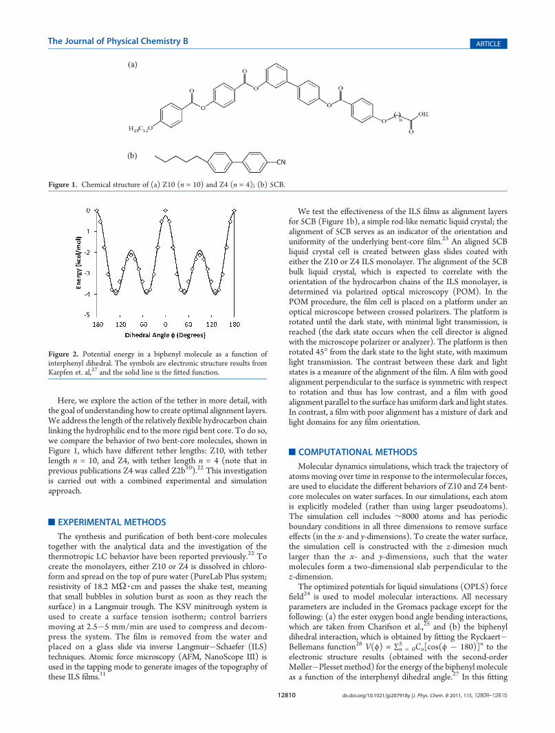
Here, we explore the action of the tether in more detail, withthe goal of understanding how to create optimal alignment layers.We address the length of the relatively flexible hydrocarbon chainlinking the hydrophilic end to the more rigid bent core. To do so,we compare the behavior of two bent-core molecules, shown inFigure 1, which have different tether lengths: Z10, with tetherlength n = 10, and Z4, with tether length n = 4 (note that inprevious publications Z4 was called Z2b10).22 This investigationis carried out with a combined experimental and simulationapproach.
’EXPERIMENTAL METHODS
The synthesis and purification of both bent-core moleculestogether with the analytical data and the investigation of thethermotropic LC behavior have been reported previously.22 Tocreate the monolayers, either Z10 or Z4 is dissolved in chloro-form and spread on the top of pure water (PureLab Plus system;resistivity of 18.2 MΩ 3 cm and passes the shake test, meaningthat small bubbles in solution burst as soon as they reach thesurface) in a Langmuir trough. The KSV minitrough system isused to create a surface tension isotherm; control barriersmoving at 2.5�5 mm/min are used to compress and decom-press the system. The film is removed from the water andplaced on a glass slide via inverse Langmuir�Schaefer (ILS)techniques. Atomic force microscopy (AFM, NanoScope III) isused in the tapping mode to generate images of the topography ofthese ILS films.11
We test the effectiveness of the ILS films as alignment layersfor 5CB (Figure 1b), a simple rod-like nematic liquid crystal; thealignment of 5CB serves as an indicator of the orientation anduniformity of the underlying bent-core film.23 An aligned 5CBliquid crystal cell is created between glass slides coated witheither the Z10 or Z4 ILS monolayer. The alignment of the 5CBbulk liquid crystal, which is expected to correlate with theorientation of the hydrocarbon chains of the ILS monolayer, isdetermined via polarized optical microscopy (POM). In thePOM procedure, the film cell is placed on a platform under anoptical microscope between crossed polarizers. The platform isrotated until the dark state, with minimal light transmission, isreached (the dark state occurs when the cell director is alignedwith the microscope polarizer or analyzer). The platform is thenrotated 45� from the dark state to the light state, with maximumlight transmission. The contrast between these dark and lightstates is a measure of the alignment of the film. A film with goodalignment perpendicular to the surface is symmetric with respectto rotation and thus has low contrast, and a film with goodalignment parallel to the surface has uniform dark and light states.In contrast, a film with poor alignment has a mixture of dark andlight domains for any film orientation.
’COMPUTATIONAL METHODS
Molecular dynamics simulations, which track the trajectory ofatoms moving over time in response to the intermolecular forces,are used to elucidate the different behaviors of Z10 and Z4 bent-core molecules on water surfaces. In our simulations, each atomis explicitly modeled (rather than using larger pseudoatoms).The simulation cell includes ∼8000 atoms and has periodicboundary conditions in all three dimensions to remove surfaceeffects (in the x- and y-dimensions). To create the water surface,the simulation cell is constructed with the z-dimesion muchlarger than the x- and y-dimensions, such that the watermolecules form a two-dimensional slab perpendicular to thez-dimension.
The optimized potentials for liquid simulations (OPLS) forcefield24 is used to model molecular interactions. All necessaryparameters are included in the Gromacs package except for thefollowing: (a) the ester oxygen bond angle bending interactions,which are taken from Charifson et al.,25 and (b) the biphenyldihedral interaction, which is obtained by fitting the Ryckaert�Bellemans function26 V(ϕ) = ∑n = 0
5 Cn[cos(ϕ � 180)]n to theelectronic structure results (obtained with the second-orderMøller�Plesset method) for the energy of the biphenyl moleculeas a function of the interphenyl dihedral angle.27 In this fitting
Figure 1. Chemical structure of (a) Z10 (n = 10) and Z4 (n = 4); (b) 5CB.
Figure 2. Potential energy in a biphenyl molecule as a function ofinterphenyl dihedral. The symbols are electronic structure results fromKarpfen et. al,27 and the solid line is the fitted function.
12811 dx.doi.org/10.1021/jp207918y |J. Phys. Chem. B 2011, 115, 12809–12815
The Journal of Physical Chemistry B ARTICLE
procedure, the parameters Cn were varied to fit the sum of V(ϕ)and the nonbonded energy (in calculating the nonbondedenergy, all bond lengths and angles remained fixed as ϕ changed).The fitted energy is compared to the electronic structure energyin Figure 2; the small differences between the fit and the energyvalues are due to the limited variability inherent in the Ryckaert�Bellemans function.
The simulations are carried out for systems consisting of 2500water molecules and either 1 or 25 bent-core molecules; thesimulations with 1 molecule represent the infinite dilution limit,and the simulations with 25 molecules represent systems withsurface areas of 0.23 nm2/molecule. The simulation cell has x-and y-dimensions of 5.4 nm and a z-dimension of 12 nm; thischoice of simulation cell dimensions leads to slabs of waterapproximately 2.7 nm thick, and the wide (>9 nm) vacuum layerseparating the water slabs ensures that the interaction betweenslabs is negligible. The starting configuration consists of theannealed bent-core molecules placed in the vacuum layer be-tween water slabs. All simulations are carried out at a temperatureof 300 K.
The simulations are carried out for 35 ns, where the first 10 nsis used for equilibration, and data is collected in the final 25 ns.The molecular structures are analyzed in terms of probabilitydistributions of the positions of different segments of themolecule. Along the z-dimension, these positions are comparedto the position of the water surface, which is defined here as theGibbs dividing surface.28
The molecular dynamics simulation details are as follows. Theparticle-mesh Ewald method29 is used to calculate the Coulom-bic interactions, and a direct summation to a cutoff length of 1 nmis used to calculate the non-Coulombic interactions. A fixedtemperature is maintained using a velocity rescaling thermostat30
with a time constant of 1 ps; the thermostat is applied separatelyfor the bent-core and water molecules to ensure the equilibrationof energy. The time step used for the numerical integration of theequations of motion is 1 fs. The simulations are carried out withthe Gromacs software package.31
The bent core molecules are initially annealed to ensure thatthey are not trapped in nonequilibrium configurations near the(arbitrary) starting configuration. The annealing is carried out forthe molecule in a vacuum, with a series of 100 ps simulations; thesimulations begin at T = 1000 K, and each subsequent simulationis run at a temperature lowered by 100 K, down to T = 300 K.
’EXPERIMENTAL RESULTS
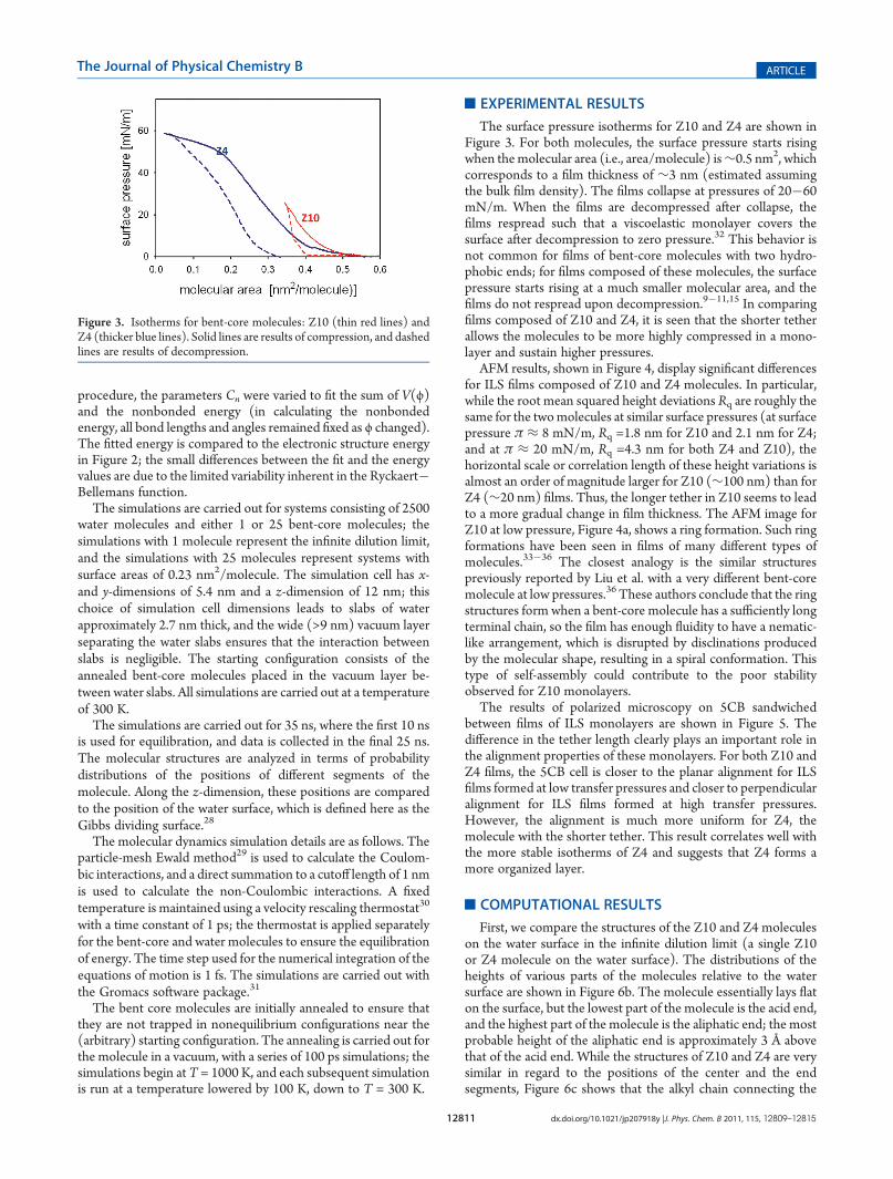
The surface pressure isotherms for Z10 and Z4 are shown inFigure 3. For both molecules, the surface pressure starts risingwhen themolecular area (i.e., area/molecule) is∼0.5 nm2, whichcorresponds to a film thickness of ∼3 nm (estimated assumingthe bulk film density). The films collapse at pressures of 20�60mN/m. When the films are decompressed after collapse, thefilms respread such that a viscoelastic monolayer covers thesurface after decompression to zero pressure.32 This behavior isnot common for films of bent-core molecules with two hydro-phobic ends; for films composed of these molecules, the surfacepressure starts rising at a much smaller molecular area, and thefilms do not respread upon decompression.9�11,15 In comparingfilms composed of Z10 and Z4, it is seen that the shorter tetherallows the molecules to be more highly compressed in a mono-layer and sustain higher pressures.
AFM results, shown in Figure 4, display significant differencesfor ILS films composed of Z10 and Z4 molecules. In particular,while the root mean squared height deviations Rq are roughly thesame for the twomolecules at similar surface pressures (at surfacepressure π ≈ 8 mN/m, Rq =1.8 nm for Z10 and 2.1 nm for Z4;and at π ≈ 20 mN/m, Rq =4.3 nm for both Z4 and Z10), thehorizontal scale or correlation length of these height variations isalmost an order of magnitude larger for Z10 (∼100 nm) than forZ4 (∼20 nm) films. Thus, the longer tether in Z10 seems to leadto a more gradual change in film thickness. The AFM image forZ10 at low pressure, Figure 4a, shows a ring formation. Such ringformations have been seen in films of many different types ofmolecules.33�36 The closest analogy is the similar structurespreviously reported by Liu et al. with a very different bent-coremolecule at low pressures.36 These authors conclude that the ringstructures form when a bent-core molecule has a sufficiently longterminal chain, so the film has enough fluidity to have a nematic-like arrangement, which is disrupted by disclinations producedby the molecular shape, resulting in a spiral conformation. Thistype of self-assembly could contribute to the poor stabilityobserved for Z10 monolayers.
The results of polarized microscopy on 5CB sandwichedbetween films of ILS monolayers are shown in Figure 5. Thedifference in the tether length clearly plays an important role inthe alignment properties of these monolayers. For both Z10 andZ4 films, the 5CB cell is closer to the planar alignment for ILSfilms formed at low transfer pressures and closer to perpendicularalignment for ILS films formed at high transfer pressures.However, the alignment is much more uniform for Z4, themolecule with the shorter tether. This result correlates well withthe more stable isotherms of Z4 and suggests that Z4 forms amore organized layer.
’COMPUTATIONAL RESULTS
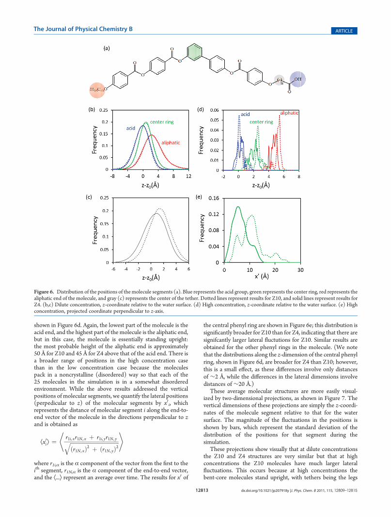
First, we compare the structures of the Z10 and Z4 moleculeson the water surface in the infinite dilution limit (a single Z10or Z4 molecule on the water surface). The distributions of theheights of various parts of the molecules relative to the watersurface are shown in Figure 6b. The molecule essentially lays flaton the surface, but the lowest part of the molecule is the acid end,and the highest part of the molecule is the aliphatic end; the mostprobable height of the aliphatic end is approximately 3 Å abovethat of the acid end. While the structures of Z10 and Z4 are verysimilar in regard to the positions of the center and the endsegments, Figure 6c shows that the alkyl chain connecting the
Figure 3. Isotherms for bent-core molecules: Z10 (thin red lines) andZ4 (thicker blue lines). Solid lines are results of compression, and dashedlines are results of decompression.

12812 dx.doi.org/10.1021/jp207918y |J. Phys. Chem. B 2011, 115, 12809–12815
The Journal of Physical Chemistry B ARTICLE
central core to the end acid group rises higher above the water forZ10 than for Z4 (note that the length of this chain is the onlydifference between Z10 and Z4). These results reinforce the ideathat the acid group is the segment of the molecule most stronglytethered to the water surface and that a longer tether is floppier.
However, for the infinite dilution case, there is not much of astructural difference between Z10 and Z4.
The results are more interesting for high concentrations, whenpacked monolayers of Z10 and Z4 are compared. The distribu-tions of the vertical positions of various parts of the molecule are
Figure 4. AFMpictures of ILSmonolayer-coated glass slides transferred from a Langmuir trough at different surface pressure. The images are 500 nm�500 nm horizontally. Top: Z10, (a) surface pressure π = 2mN/m,mean squared deviation Rq = 1.7 nm; (b) π = 8mN/m, Rq = 1.8 nm; (c)π = 17mN/m,Rq = 4.33. Bottom: Z4, (a) π = 8 mN/m, Rq = 2.2 nm; (b) π = 21 mN/m, Rq = 4.3 nm; (c) π = 33 mN/m, Rq = 6.5 nm.
Figure 5. Polarized optical microscopy (POM) images for 5CB cells sandwiched with ILS-coated glass slides at different surface pressures. Left: Z10,(a) 3 mN/m, (b) 10 mN/m, and (c) 20 mN/m. Right: Z4, (a) 8 mN/m, (b) 21 mN/m, and (c) 33 mN/m. For each set of results, the left imagerepresents the dark state, and the right image represents the light state (described in Experimental Methods); the rotation between these images is 45�counter-clockwise. The crossed arrows indicate the direction of the polarizer and analyzer, and the bar is 200 μm.
12813 dx.doi.org/10.1021/jp207918y |J. Phys. Chem. B 2011, 115, 12809–12815
The Journal of Physical Chemistry B ARTICLE
shown in Figure 6d. Again, the lowest part of the molecule is theacid end, and the highest part of the molecule is the aliphatic end,but in this case, the molecule is essentially standing upright:the most probable height of the aliphatic end is approximately50 Å for Z10 and 45 Å for Z4 above that of the acid end. There isa broader range of positions in the high concentration casethan in the low concentration case because the moleculespack in a noncrystalline (disordered) way so that each of the25 molecules in the simulation is in a somewhat disorderedenvironment. While the above results addressed the verticalpositions of molecular segments, we quantify the lateral positions(perpedicular to z) of the molecular segments by x0i, whichrepresents the distance of molecular segment i along the end-to-end vector of the molecule in the directions perpendicular to zand is obtained as
Æx0iæ ¼r1i, xr1N, x þ r1i, yr1N , yffiffiffiffiffiffiffiffiffiffiffiffiffiffiffiffiffiffiffiffiffiffiffiffiffiffiffiffiffiffiffiffiffiffiffiffiðr1N, xÞ2 þ ðr1N , yÞ2
q* +
where r1i,α is the α component of the vector from the first to theith segment, r1N,α is the α component of the end-to-end vector,and the Æ...æ represent an average over time. The results for x0 of
the central phenyl ring are shown in Figure 6e; this distribution issignificantly broader for Z10 than for Z4, indicating that there aresignifcantly larger lateral fluctutions for Z10. Similar results areobtained for the other phenyl rings in the molecule. (We notethat the distributions along the z-dimension of the central phenylring, shown in Figure 6d, are broader for Z4 than Z10; however,this is a small effect, as these differences involve only distancesof ∼2 Å, while the differences in the lateral dimensions involvedistances of ∼20 Å.)
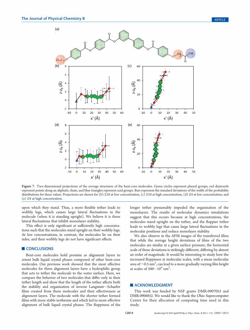
These average molecular structures are more easily visual-ized by two-dimensional projections, as shown in Figure 7. Thevertical dimensions of these projections are simply the z-coordi-nates of the molecule segment relative to that for the watersurface. The magnitude of the fluctuations in the positions isshown by bars, which represent the standard deviation of thedistribution of the positions for that segment during thesimulation.
These projections show visually that at dilute concentrationsthe Z10 and Z4 structures are very similar but that at highconcentrations the Z10 molecules have much larger lateralfluctuations. This occurs because at high concentrations thebent-core molecules stand upright, with tethers being the legs
Figure 6. Distribution of the positions of the molecule segments (a). Blue represents the acid group, green represents the center ring, red represents thealiphatic end of the molecule, and gray (c) represents the center of the tether. Dotted lines represent results for Z10, and solid lines represent results forZ4. (b,c) Dilute concentration, z-coordinate relative to the water surface. (d) High concentration, z-coordinate relative to the water surface. (e) Highconcentration, projected coordinate perpendicular to z-axis.
12814 dx.doi.org/10.1021/jp207918y |J. Phys. Chem. B 2011, 115, 12809–12815
The Journal of Physical Chemistry B ARTICLE
upon which they stand. Thus, a more flexible tether leads towobbly legs, which causes large lateral fluctuations in themolecule (when it is standing upright). We believe it is theselateral fluctuations that inhibit monolayer stability.
This effect is only significant at sufficiently high concentra-tions such that the molecules stand upright on their wobbly legs.At low concentrations, in contrast, the molecules lie on theirsides, and their wobbly legs do not have significant effects.
’CONCLUSIONS
Bent-core molecules hold promise as alignment layers toorient bulk liquid crystal phases composed of other bent-coremolecules. Our previous work showed that the most effectivemolecules for these alignment layers have a hydrophilic groupthat acts to tether the molecule to the water surface. Here, wecompare the behavior of two molecules that differ only in theirtether length and show that the length of the tether affects boththe stability and organization of inverse Langmuir�Schaeferfilms created from these molecules and their effectiveness asalignment layers. The molecule with the shorter tether formedfilms with more stable isotherms and which led to more effectivealignment of bulk liquid crystal phases. The floppiness of the
longer tether presumably impeded the organization of themonolayers. The results of molecular dynamics simulationssuggest that this occurs because at high concentrations, themolecules stand upright on the tether, and the floppier tetherleads to wobbly legs that cause large lateral fluctuations in themolecular positions and reduce monolayer stability.
We also observe in the AFM images of the transferred filmsthat while the average height deviations of films of the twomolecules are similar at a given surface pressure, the horizontalscale of these deviations is strikingly different, differing by almostan order of magnitude. It would be interesting to study how theincreased floppiness at molecular scales, with a mean moleculararea of∼0.5 nm2, can lead to amore gradually varying film heightat scales of 500�104 nm2.
’ACKNOWLEDGMENT
This work was funded by NSF grants DMR-0907055 andDMR-0906852. We would like to thank the Ohio SupercomputerCenter for their allocation of computing time used in thisstudy.
Figure 7. Two-dimensional projections of the average structures of the bent-core molecules. Green circles represent phenyl groups, red diamondsrepresent points along an aliphatic chain, and blue triangles represent acid groups. Bars represent the standard deviations of the width of the probabilitydistributions for these values. Projections are shown for (b) Z10 at low concentration, (c) Z10 at high concentration, (d) Z4 at low concentration, and(e) Z4 at high concentration.
12815 dx.doi.org/10.1021/jp207918y |J. Phys. Chem. B 2011, 115, 12809–12815
The Journal of Physical Chemistry B ARTICLE
’REFERENCES
(1) Takezoe, H.; Takanishi, Y. Jpn. J. Appl. Phys. 2006, 45, 597–625.(2) Araoka, F.; Sugiyama, G.; Ishikawa, K.; Takezoe, H. Opt. Mater.
2011, 1, 27–35.(3) Pelzl, G.; Diele, S.; Weissflog, W. Adv. Mater. 1999, 11, 707–724.(4) J�akli, A.; Kr€uerke, D.; Nair, D. G. Phys. Rev. E: Stat., Nonlinear,
Soft Matter Phys. 2003, 67, 051702.(5) Verduzco, R.; Luchette, P.; Hong, S. H.; Harden, J.; DiMasi, E.;
Palffy-Muhoray, P.; Kilbey, S. M., II; Sprunt, S.; Gleeson, J. T.; J�akli, A.J. Mater. Chem. 2010, 20, 8488–8495.(6) Link, D. R.; Natale, G.; Shao, R.; Maclennan, J. E.; Clark, N. A.;
K€orblova, E.; Walba, D. M. Science 1997, 278, 1924–1927.(7) Niori, T.; Sekine, T.; Watanabe, J.; Furukawa, T.; Takezoe, H.
J. Mater. Chem. 1996, 6, 1231.(8) Sekine, T.; Niori, T.; Sone, M.; Watanabe, J.; Choi, S. W.;
Takanishi, Y.; Takezoe, H. Jpn. J. Appl. Phys. 1997, 36, 6455–6463.(9) Mann, E. K.; Iglesias, W.; Smith, T.; Basnet, P.; Lacks, D. J.; J�akli,
A. Emerging Liquid Crystal Technologies VI, SPIE Proceedings, SanFrancisco, CA, Jan 22�27, 2011; paper no. 7955�17(10) Iglesias, W.; Smith, T. J.; Basnet, P. B.; Stefanovic, S. R.;
Tschierske, C.; Lacks, D. J.; J�akli, A.; Mann, E. K. Soft Matter 2011,7, 9043–9050.(11) Wang, J.; Qiu, L.; J�akli, A.; Weissflog, W.; Mann., E. K. Liq.
Cryst. 2010, 37, 1229–1236.(12) Kinoshita, Y.; Park, B.; Takezoe, H.; Niori, T.; Watanabe, J.
Langmuir 1998, 14, 6256–6260.(13) Ashwell, G. J.; Amiri, M. A. J. Mater. Chem. 2002, 10, 2181.(14) Baldwin, J. W.; Amaresh, R. R.; Peterson, I. R.; Shumate, W. J.;
Cava, M. P.; Amiri, M. A.; Hamilton, R.; Ashwell, G. J.; Metzger, R. M.J. Phys. Chem. B 2002, 106, 12158.(15) Zou, L.; Wang, J.; Beleva, V. J.; Kooijman, E.; Primak, S. V.;
Risse, J.; Weissflog, W.; J�akli, A.; Mann, E. K. Langmuir 2004, 20, 2772.(16) Blinov, L. M.; Geivandov, A. R.; Lazarev, V. V.; Palto, S. P.;
Yudin, S. G.; Pelzl, G.; Weissflog, W. Appl. Phys. Lett. 2005, 87, 241913.(17) Blinov, L. M.; Palto, P.; Lazarev, V. B.; Geivandov, A. R.;
Yuding, S. G. Crystallogr. 2006, 51, 843–849.(18) Geivandov, A. R.; Alto, S. P.; Yudin, S. G.; Blinov, L. M.; Pelzl,
G.; Weissflog, W. Ferroelectrics 2006, 344, 247–254.(19) Wang, J.; Zou, L.;Weissflog,W.; J�akli, A.; Mann, E. K. Langmuir
2006, 22, 3198–3206.(20) Duff, N.; Wang, J.; Mann, E. K.; Lacks, D. J. Langmuir 2006,
22, 9082–9085.(21) Duff, N.;Mann, E. K.; Lacks, D. J. Langmuir 2008, 24, 4456–4460.(22) Kardas, D.; Prehm, M.; Baumeister, U.; Pocienta, D.; Reddy,
R. A.; Mehl, G. H.; Tschierske, C. J. Mater. Chem. 2005, 15, 1722–1733.(23) Fang, F. Y.; Gehlert, U.; Shashidar, R.; C. M. Knobler, C. M.
Langmuir 1999, 15, 297.(24) Jorgensen, W.; Maxwell, D.; Tirado-Rives, J. J. Am. Chem. Soc.
1996, 118, 11225.(25) Charifson, P.; Hiskey, R.; Pedersen, L. J. Comput. Chem. 1990,
11, 1181.(26) Ryckaert, J.; Bellemans, A. Chem. Phys. Lett. 1975, 30, 123.(27) Karpfen, A.; Choi, C.; Kertesz, M. J. Phys. Chem. 1997,
101, 7426.(28) Wang, J.; Kallnichev, A. G.; Kirkpatrick, R. J. J. Phys. Chem.
2009, 113, 11077–11085.(29) Darden, T.; Perera, L.; Li, L.; Pedersen, L. Structure 1999, 7,
R55–R60.(30) Bussi, G.; Parrinello, M. Comput. Phys. Commun. 2008, 179, 26.(31) Hess, B.; Kutzner, C.; van der Spoel, D.; Lindhal, E. J. Chem.
Theory Comput. 2008, 4, 435–447.(32) Basnet, P. Patterns and Conformations in Molecularly Thin
Films. Ph.D. Dissertation, Kent State University, 2010.(33) Latterini, L.; Blossey, R.; Hofkens, J.; Vanoppen, P.; De Schryver,
F. C.; Rowan, A. E.; Nolte, R. J. M. Langmuir 1999, 15, 3582–3588.(34) Cheyne, R. B.; Moffitt, M. G. Langmuir 2005, 21, 5453–
5460.
(35) Liu, L.; Kim, J.-K.; Gunawidjaja, R.; Tsukruk, V. V.; Lee, M.Langmuir 2008, 24, 12340–12346.
(36) Liu, L.; Kim, H. J.; Lee, M. Soft Matter 2011, 7, 91–95.