Embed Size (px)
Citation preview
AD-A239 500
NASA III0wIUIIII AVSCOMTechnical Memorandum 104388 Technical Report 91-C-015
Effects of Rim Thickness onSpur Gear Bending Stress
GD. Bibel, S.K. Reddy, and M. SavageUniversity of AkronAkron, Ohio
and
RF. Handschuh OTICPropulsion DirectorateU.S. Army Aviation Systems Command UG3 LECTLewis Research Center S AUG•3 lasiUCleveland Ohio
Prepared for the27th Joint Propulsion Conferencecosponsored by the AIAA, SAE, and ASME
A Sacramento, California, June 24-26, 1991
Dmma-MoN sTATIM-rr A
IApp=*rd iaz publiC rs"
I'RJASA A'.TM T ARMT
91-07593INERM1: pi 19! 043

EFFECTS OF RIM THICKNESS CH SPUR GEAR BENDING STRESS
G.D. Bibel, S.K. Reddy, and H. SavageUniversity of Akron
Akron, Ohio 44325
and
R.F. HandschuhPropulsion Directorate
U.S. Army Aviation Systems CommandLewis Research CenterCleveland, Ohio 44135
Abstract N number of teeth
Thin rim gears find application in 0 gear or pinion centerhigh-power, lightweight aircraft trans-missions. Bending stresses in thin rim p5 base pitch (in.,spur gear tooth fillets and root areasdiffer from the stresses in solid gears P, diametral pitch (in.-')due to rim deformations. Rim thickness
Sis a significant design parameter for R pitch radius (in.)u these gears. To study this parameter, a
finite element analysis was conducted on s tooth surface location from lefta segment of a thin rim gear. The rim edge (in.)thickness was varied and the location andmagnitude of the maximum bending stresses t rim depth (in.)reported. Design limits are discussedand compared with the results of other u line of action location of gearresearchers. addendLm circle (in.)
Nomenclature V, relative velocity between cutter andgear blank (in./sec)
A point at the end of the line ofaction at the gear base circle , rim tackup ratio
B highest point of single tooth con- 7 rim location angle (deg)tact on pinion tooth
e roll angle (deg)C point at the intersection of the
gear addendum circle and the line of ac maximum compressive stress (ksi)action
0 rim surface stress (ksi)D point at the end of the line of
action at the pinion base circle as maximum stress range (ksi)
F force (lb) a. tooth surface stress (ksi)
h tooth height (in.) a- maximum tensile stress (ksi)
M support moment about edge centrode 0.._ base maximum tensile stress (ksi)(lb-in.)
# pressure angle (deg)n cuter surface normal unit v-ctor
Subscripts bending stresses in a gear tooth of asolid gear and demonstrated good agree-
ag gear addendum ment with photoelastic stress measure-ments.
B highest point of single toothcontact For thin rim gearing, Drago
et al.3" studied rimmed gear stresses
g gear experimentally with strain gages andphotoelastic models and analytically with
i node count index two and three-dimensional finite elementmodels. Their studies report a nearly
j node index constant bending stress as the rim thick-ness decreases and a sudden increase in
1 left end bending stress below a certain rimthickness-
p pinionAnalytical studies have been con-
r right end ducted on thin rin gear stresses withfinite elements by several researchers.
x horizontal Oda et al. studied a single tooth modelof a thin rim spur gear using a five
y vertical tooth segment fixed at its sides. Theyused strain gages to verify their
Introduction results. Arai et al.6
studied a spokedthin rim gear with four teeth in the free
One major cause of gear failure is rim arc between spokes. Chang et al.'fracture at the base of the gear tooth applied a two-d--ensional finite elementdue to bending fatigue. Design models grid to a single thin rim tooth withfor this mode of failure use a parabolic fixed constraints at the tooth sides tobeam with stress concentration correc- demonstrate the stress distribution intion.' The bending strength is influ- the tooth. Chong et al.- used two-enced by: the gear size, described by dimensional triangular finite elementsthe diametral pitch; the shape of the and a rack model to study the effects oftooth, described by the number of teeth the rim on the bending stress in the fil-on the gear; the highest location of the let. Their rack model had staticallyfull load, described by the number of determinate beam supports on segments ofteeth on the mating gear; and the fillet different lengths. Von Eiff et al.9 usedgeometry of the gear tooth. The present a finite element model of a three toothAGMA design model treats these factors segment for both external and internaldirectly and by extrapolating limited gears to study the maximum bendingexperimental data for the stress concen- stresses at the root of the centraltration correction, tooth. Gulliot and Tordion'0 analyzed
the problem of a thin rim on a supportFor thin rim gears, the thickness of hub using the finite element method.
the rim is another significant factorwhich influences the bending strength of All of these studies report a nearlythe gear. Rim deflections increase the constant tensile bending stress as thebending stresses in the tooth fillet and rim thickness decreases to a value nearroot areas. Therefore in aircraft appli- the tooth depth. The tensile root stresscations, the rim thickness and allowable increases rapidly with further reductionsstress are optimized to achieve light of rim thickness. However, each studyweight, reported a different transition rim
thickness value. These studies also dif-Wilcox and Coleman2 applied the fered in the rim support geometry and the
finite element method to analyze the number of teeth cn the gear. The ring
2
flexibility of the rim influences both Coordinates for the surface profilethe tooth stiffness' and the location of the tooth come from a kinematic analy-and magnitude of the maximum bonding sis of the cutting process.12 Both thestress in a thin rim gear. Thus, the rack form cutter and the resulting gearsupport constraints affect the maximum surface are tangent to each other at thebending stress. cutting points, which generate the gear
shape from the rack shape. At the cut-Herein, a five tooth segment of a ting points, the rack form and gear blank
25 tooth gear in mesh with a 50 tooth have a relative velocity which acts ingear is studied. A rack tip generated the tangential cutting direction in thetrochoid fillet1
2 is at the base of the plane of the gears. One can find the
involute to describe accurately the coordinates of the cut points on the gearstructural geometry of the tooth. The as the locus of coincident points forrim depth to tooth height ratio is varied which the relative velocity is tangent toto study its effects on the bending ten- the rack form surface. The dot productsile and compressive stresses at the base of the surface normal to the rack form,of the loaded tooth and to investigate n, with the relative velocity between thethe support loading and its influence on tool and blank, V.,, is zero at thesethe bending stresses, points:
Gear Tooth Geometry n-v =0 (1)
The pinion studied had a diametral The involute is generated by pointspitch of 10, 25 teeth, and a nominal on the side of the rack form, the gearpressure angle of 200. The pinion and tooth fillet is generated by the tip ofmating 50 tooth gear had standard full the rack form, and the bottom land isdepth teeth with addendum ratios of 1.0 generated by the top surface of the rackand dedendum ratios of 1.35. The rack form tooth.form cutter tip had a sharp corner andthe face width of the gears was 0.625 in. The load on the central tooth of theA 500 lb load acted between the gears finite element model, which produces thealong the line of action corresponding to largest bending stress, is the full loada pinion torque of 537.3 lb-in. with no acting at the highest point of singledynamic loading factor. Table I su=mua- tooth contact. '4"3 Figure 2 shows therizes the geometry of the gear mesh. gears in mesh with the pinion tooth
loaded at the highest point of singleDevelopment of the finite element tooth contact. This location, point B,
model begins with data describing .he is one base pitch above the addendum cir-outline of a single tooth and its fillets cle of the mating gear, point C, on thefrom the center of the tooth space on one line of action. The distance from theside to the center of the tooth space on addendum circle on the mating gear to thethe other side. Several different curves base circle of the pinion, point D, alongmake up the tooth outline: concentric the line of action, called u is:circular arcs at the outside tooth tipand the bottom tooth space lands, invo-lutes on the two sides of the tooth, and u =AD - ACtrochoides between the involutes and theFigure 1 identifies these curves on the R sin R9 H o 2)
tooth outline. The tooth side involutes,fillet trochoides, and bottom lands are where R is the pitch radius of theshaped to model a gear cut with a rack pinion, is the Ditch radius of theform cutter. mating gear, and R is the addendum or
,.1L Srpecial,
'3I

outside radius of the mating gear. The which has different radii for the differ-roll angle, e.. to the highest point of ent rim thickness ratio cases. Both thesingle tooth loading on the pinion is: tooth surface and the inside ri. surface
arc unconstrained. At the sides, two
02 .u ( p) radial lines, at t36° from the segment
Rc Cos center, complete the outline of themodel.
where p. is the base pitch of the gear Rim support was modeled by con-mesh. The base pitch is related to: the straining the radial side cuts in thepitch radius of the pin-on, R ; the nomi- gear rim at all node points to have zeronal pressure angle, 0; and the number of displacement. The load of 500 lb wasteeth on the pinion, N; by applied at the highest point of single
tooth contact on the central tooth in the21'R direction of the line of action. To
S. c( apply the load at a node, the grid had to
have a node point at or near this loadingpoint.
This roll angle, 0 , determines thepressure angle at the highest point of A six node iso-parametric plane-single tooth contact, 0', and the radius stress triangular element was used toto that point on the tooth surface, Rs. build the finite element models insideThe pressure angle between the line of the frameworks described above. Thisaction and the circumferential direction element has a quadratic displacementat the highest point of single tooth con- function and is well-suited for analyzingtact, 0," is: irregular shapes. A lattice of three
integration points is used with the- tan-'B, (5) numerical (Gaussian) integration proce-
dure. Each node in the element has2 degrees of freedom - translations in
The radius to that point is: the x and y directions. The planestress option with unit thickness was
R3 Cos 6 used and scaled to the actual modelCos 03 thickness of 0.625 in. As can be seen in
Figs. 3 and 4, a fine mesh was used in
the root and fillet areas of all teeth.With the appropriate rotations, this Figure 4 shows the left side of the cen-
slope and radius locates the oirection tral tooth which had an even finer ele-and point of application of the gear mesh ment spacing of about 0.004 in. on bothforce on the central tooth in the five sides to provide more accurate infor--a-tooth segment model. tion on the stress in these regions. The
complete model has 1308 elements, 2777Finite Element Model nodes, and 5554 degrees of freedom.
A model consisting of a five tooth To evaluate segments with differentsection of a 25 tooth pinion was devel- rim thicknesses, the lower elements inoped with the general purpose finite ele- the rim below the tooth and a minimum rimment program."* Figure 3 shows the thickness were placed in eight concentricfinite element grid for the five tooth rings of equal thickness. Nine separategear segment. Successive reflections of models -ere obtained by removing succes-the coordinates for the initial tooth sive rings of inside elements. This var-generated a segment of five equally ied the backup ratio of rim thickness tospaced, identical teeth. The inside edge full tooth height from a maximum value ofof the model is a constant radius arc 2.55 down to a minimum value of 0.45.
4

Bending Stresses largest ratio of P = 2.55 while thesolid curve is for the smallest backup
To aid in visualization, the extrap- ratio of p = 0.45.olated nodal stresses along the top andbottom surfaces of the gear tooth segment in these plots, one can see highmodel were plotted versus position on the bending tensile and compressive stressessegment. These stresses were studied for in the roots R2 and R3, imzediatelythe case of full load at the highest before and after the loaded tooth.point of single tooth contact and for two Smaller bending tensile and compressiveother cases of shared loading at the stresses are present in the roots R1 andtooth tip which produced lower stresses. R4 which are one tooth further away fromThe cases with lower bending stresses'3 the loaded tooth. Even smaller tensileare not presented here. and compressive stresses are present at
El and E2 in the roots at the seg-entFigure 5 shows the five tooth seg- boundaries where the fixed constraints
ment with some labeling and both the are present.thinnest and thickest rims. Circumferen-tial locations are labeled Ti through T5, Figure 7 has similar plots of theR1 through R4, and El and E2 to repre- surface normal stress on the rim bottomsent: the middle of the tooth tops at Tl surface, a-, for the same backup ratiosto T5, the middle of the tooth spaces at of 2.55 and 0.45. These plots are drawnR1 to R4, and the left and right sides of versus a central angle, 7, measuredthe segment at El and E2. clockwise from the left edge of the seg-
ment. An angular measure of location, 7,The full tooth height is laneled h, provides similar direct comparisons among
and Fig. S shows both the minimum rim, these plots for the different backupt,,-, and maximum rim, t_, cases super- ratios. The labeling points T1 tnroughimposed on each other. The backup ratio, T5 and Rl tisrough R4 lcate the teeth inP, of rim thickness to tooth height is the plots and match the rim bottomdefined as: stresses to the tooth surlace stresses.
p= (7) The surface stresses in the rim bot-h tom, a, aze ring flexing stresses. They
also combine with the top surface stress,To locate the stresses along the U, to describe partially the support
teeth, the surface distance from the left loading which is statically indetermi-edge of the segment, El, to node j, s, nate. in all cases, larger surfaceswas calculated as: stresses at the right segment edge indi-
cate larger support reactions at the(: ~right than at the left. The comprssv e
a = x~ ÷ Ay~ (81 load path to the loaded tooth in the archis stiffer than the tensile load pathbehind the tooth due to the orientation
where Ax, is the incremental distance of the load. However, integration of thebetween surface nodes in the x direc- fixed boundary stresses is necessary totion at node i and hy. is the incre- determine the full support normal, shearmental distance between surface nodes in and moment reactions.the y direction at node i.
Figure 8 is a force diagram of theFigure 6 contains plots of the prin- thinnest rim segment with its applied and
cipal stress in the plane of the tooth support loading. As indicated by thesurface, a, as a function of the dis- size of the arrows and the magnitudes oftance, a, from the left edge of the seg- the edge stresses in Figs. 6 and 7, thement for the largest and smallest backup primary support for the load is from theratios. The dashed curve is for the right side, with a shear load dominating
5
the left side reactions. Both sides have a rim flexing stress which increases assmall support moments in this thin rim the rim thickness decreases. This com-case which are shown as slight displace- pressive stress, which acts on the topments of the support reactions from the surface of the segment, is caused by therim section centers. Table II lists the radial component of the tooth load. Thusleft and right support reactions for the compressive stress is superimposed onnine rim thickness cases studied, both the tensile and compressive tooth
bending stresses by the rim flexibility.The influence of rim thickness on These additional compressive stresses are
the bending stresses is sursarized in responsible for the decrease in maximumFig. 9. The figure plots the maximum tensile tooth bending stress with atensile, q, and compressive, 0, stress- decrease in rim thickness. The effectes at the base of the loaded tooth, and also causes the maximum compressive bend-the maximum stress range, o,, in this ing stresses on the tooth root to stead-region as a function of the backup ratio, ily increase with decreasing backupp. The maximum stress range, a., is ratio.twice the mzximue alternating stress inthe tooth root. Since only one tooth was Stress Comparisonsloaded in this model, the stress rangewas calculated as the difference between The influence of the rim on thethe stresses in the root at one side of tensile, compressive and alternatin;the loaded tooth and those at similar stresses noted in this work trs Lea-points c-: t'te otier side of the loaded observed by others.'-'* In the ctne= stu-tooth oni Full tooth surface distance dies on rim thicknert effects, cnivaway. 11 t.-hse stresses are divided Drago"'• applies the load at the highes-by tre eaximus tensile tooth surface point of single tOotn contact on the sic-
stress for the thickest rim case, _. ion. This is the loading condition whichThis base strss, a_, is close to the produces the highest cending stresses inmaximum tensile bending stress for a the tooth and the ri4. The cases ofsolid gear. Ratics to this stress, 0,, shared load as a pinion tooth enters andgive the relative magnitudes of the eaxi- leaves the loaded region were studied inmum thin rim surface stresses. this work aiso.' On entering the mesh,
a pinion tooth sees load near its baseThe maximum tensile t. -"s acts from thc tip of the gear tooth, while its
higher on the tooth than the so~xi== coo- preceding tooth sees load at its highestpressive stress or tho ma,*:,m stress potnt .: single tooth contact. On leav-variation act. The plot shc.s a =-all in' th, i.esh, a pinion tooth sees load atreduction in the tensile stress as the i3s z-p. -hile its following tooth seesbackup ratio decreases to a value of 16e aet Ir lowest point of single toothabout 0.7. Below this value, the tensile tootai.. The loads %ere assumed to bestress rises with further reductions in shared equally between the two teeth.rim thickness. Both additional cases produced lower
bending stresses in this study.It should be noted that both the
compressive and the alternating stresses, All other studies5-' placed the full
which act lower on the tooth, rise as the load at the tip of the pinion tooth.rim thickness decreases. However, these Although the full load does not act atstresses only begin to rise appreciably the pinion tooth tip in practice, theat a backup ratio of 1.2 or less. results of the studies agree in principal
with the results presented here.The reduction in maximum tensile
stress at the root of the tooth with, the Other differences between the stud-reduction in backup ratio is surprising. ies include the number of teeth on theHowever, both the tensile and compressive loaded gear and the elastic support fortooth bending stresses are influenced by the loaded gear segment. Table III
6

summarizes these differences and presents The tensile stresses decreasedthe rim backup ratio of each study for slightly with decreases in backup ratiowhich the thin rim gear bending stresses until a value of 0.7 was reached. Atincrease over those for a similar solid this value the maximum tensile bendinggear. A brief description of each model stress increased with further decreasesis included in the table. The models in the rim backup ratio.were both experimental and analytical.Both strain gage measurements and photo- 3oth the maximum compressive and theelastic models provided validation for maximum alternating bending stresses inthe numerical finite element studies. the tooth root increased with decreasesSupport configurations included: fixed in tha rim backup ratio. These increasessides for short rim segments, beam sup- were not significant until the backupports with axial expansion allowed, hub ratio dropped to values below 1.3.support under the rim, and spoke supportat the segment edges. In comparing the The general trends of increasingstudies, the dominant influence appears tensile and compressive bending stressesto be the stiffness of the rim support with decreasing backup ratio agree withconfiguration. Stiffer support geome- the published literature. Differences intries permit thinner rims without the reported backup ratio at which theincreasing the rim bending stresses. increases become measurable were seen to
depend primarily on rim support geometry.Different rim designs will behave The stiffer the rim support, the lower is
differently as the different studies sug- the backup ratio at which the stressesgest. The objective of these studies was increase over those of a similar solidto find the limit at which thin rim gear gear.bending stresses increase over those of asolid gear. In this light, a backup Referencesratio of 1.2 as suggested by the AGMAdesign code' appears to be prudent. In I. 'Fundamental Rating Factors and Cal-future work, the ring size, gear loading, culation Methods for involute Sourand support geometry differences produced and Helical Gear Teeth,- ANSI/AGMAby varying the number of teeth should be 2001-B88, American Gear Manufactur-investigated to obtain design modifica- ers Association, Arlington, VA,tion factors for thin rim designs. These i988.studies should be conducted an a modelwhich properly provides the minimum prac- 2. Wilcox, L. and Coleman, W., "Appli-tical elastic support for the thin rim cation of Finite Elements to thegear. Analysis of Gear Tooth Stresses,"
Journal of Engineering for Industry,Summary Vol. 95, No. 4, Dec. 1973,
pp. 1139-1148.A study was conducted on the bending
stresses in a thin rim spur pinion with 3. Drago, R.J., Brown, F.W., and2S teeth in mesh with a 50 tooth gear. Faust, H.S., "Recent Advances in theThe study used a finite element model of Evaluation of Stresses in Light-a five tooth segment with the central ueight, High-Speed, Heavily Loadedtooth loaded at the highest point of sin- Gearing," Reliability, Stress Analy-gle tooth contact and the edges rigidly sis and Failure Prevention Methodssupported. At backup ratios above 1.3, in Mechanical Design,no appreciable change in the -_axim-M ten- W.D. Milertone, ed., ASME, 1980,sile, compressive or alternating bending pp. 225-235.stresses at the base of the loaded geartooth over those for a solid gear wereobserved.
7
4. Drago, R.J. and Lutthans, R.V.,"Com- 9. von Eiff, H., Hirschmann, K.H. andbined Effects of Rim Thickness and Lechner, G., "Influence of GearPitch Diameter on Spur Gear Tooth Tooth Geometry on Tooth Stress ofStresses," Journal of the American External and Internal Gears," Jour-Helicopter Society, Vol. 28, No. 3, nal of Mechanical Design, Vol. 112,July 1983, pp. 13-19. No. 4, 1990, pp. 575-583.
5. Oda, S., Nagamura, K., and Aoki, K., 10. Gulliot, M. and Tordion, G.V.,"Stress Analysis by Thin Rim Spur "Stress Analysis of Thin Rim SpurGears by Finite Element Method,- Gears by Finite Element Method,-Bulletin of the Japanese Society of 1989 International Power Transmis-Mechanical Engineers, Vol. 24, sion and Gearing Conference, Vol. 1,No. 193, 1981, pp. 1273-1280. ASME, New York, 1989, pp. 167-172.
6. Arai, N., Harada, S., and Aida, T., 11. Savage, M., Caldwell, R.J.,"Research on Bending Strength Prop- Wisor, G.D., and Lewicki, D.G.,erties of Spur Gears with a Thin "Gear Mesh Compliance Modeling,"Rim," Bulletin of the Japanese NASA TM-88843, 1986.Society of Mechanical Engineers,Vol. 24, No. 195, 1981, 12. Hefeng, B., Savage, M., andpp. 1642-1650. Knorr, R.J., -Computer Modeling of
Rack Generated Spur Gears," Mecha-7. Chang, S.H., Huston, R.L., and nism and Machine Theory, Vol. 20,
Coy, J.J., "A Finite Element Stress No. 4, 1985, pp. 351-360.Analysis of Spur Gears IncludingFillet Radii and Rim Thickness 13. Reddy, S.K., "RLm Effects on SpurEffects," Journal of Mechanisms, Gear Bending Stresses," M.S. Thesis,Transmissions and Automation in Univ. of Akron, Akron, OH, 1991.Design, Vol. 105, No. 3, Sept. 1983,pp. 327-330. 14. DeSalvo, G.J. and Gorman, R.W., A:SYS
Engineering Analysis System, Uset's8. Chong, T.H., and Kubo, A., -Simple Manual. Pittsburgh, PA, 1987.
Stress Formulas for a Thin-RimmedSpur Gear," Journal of Mechanisms,Transmissions and Automation inDesign, Vol. 1C7, No. 3, Sept. 1985,pp. 406-423.
8

TABLE I. - GEAR MESH GEOMETRY AND LOADING LOCATION
(a) Gear mesh geometry
Pinion Gear
Number of teeth 25 50Pitch radius, in. 1.25 2.50Base radius, in. 1.1746 2.3492Addendum radius, in. 1.35 2.60Dedendum radius, in. 1.115 2.365
Face width, w, in. 0.625Pressure angle, S, deg 20Diametral pitch, Pd' in.- 10Base pitch, p., in. 0.2952
(b) Load and location
Load, F, lb ................ .................. 500Minimum pinion curvature radius, u, in. . . 0.1685Pinion roll angle to load, 0, deg ...... .. 22.62Pinion pressure angle at load, ý,, deg . . . 21.544Pinion radius to load, R., in .......... .. 1.263
TABLE II. - GEAR SEGMENT SIDE REACTIONS
Left end Right end
F, I, M, F., F, M,lb li lb-in. lb lb lb-in.
0.45 -112 120 4 368 637 31.72 -141 176 18 397 581 40.98 -170 218 34 426 538 51
1.24 -195 248 51 451 509 681.50 -217 267 "1 474 490 901.76 -236 279 93 492 478 1162.02 -249 287 116 505 470 1462.28 -258 291 142 515 465 laO2.55 -264 2941 168 520 463 216
9

TABLE III. - LOWEST BACKUP RATIO LIMITS AT WHICH THIN RIM GEAR STRESSES EQUAL
SOLID GEAR STRESSES
Gear Teeth Backup Model description Referenceteeth in ratio
segment curveknee
1.2 Appendix design guide 120,40,80 5 1.7 Photoelastic and finite element 3,4
72 1 '0.43 Single tooth on a five tooth segment 5b1.7
30 4 1.11 Spoke model with four teeth between spokes 618 1 '0.43 Rigid support at tooth edge 7
b0.85
Rack 2,6,10 '1.33 Flexible model with simply supported 82.67 beam ends
25,50 3 a0.67 Rigid support at segment edges 91l.4
40 3 0.62 Hub support under rim 100.71
25 5 '0.7 Rigid support at segment edges 14
1 b .3
Tensile.'Compressive.
0colard
-ýScz-ram Lanc~sFigure I -Gear MOom eu*.Ee for 25 =Loom 4cn.
10

ZA
F'
P.8Line of accn
Figure 2.-4Nghesl pc~t cf srjgý- -4c0th =cnad.
Figue 4.-Le'l ha~f of certf23 =CiMn gea:segirkm~ fir.;e elerrnent rcdel.
.2 ~
FQ
Figure 3 -Five 100111 gear segwnlo f1.:e elemento lTrdei
Fiur 5-LoaCW 15fýe 100111 gear segment0 0mC-eI st=- tc11Mwm'4esl L'Id thlcest se---=o

F30
15
o FM
TI R1 T2 R2T3 T R-'T5 E2
-45
-60 F I I0 .5 1.0 1.5 2.0 2Z5 30 3.Zs (Tooth sue-ce dm.c m.
R7g-re 6 -4cc01 surla~S s..esses. Fi-;oe 8 -S!.wcr lca6,g tor ?e:01seg7rme11 mcc1eL
41F
3
- 20 -~ E_ _ _ _ _ _ _ _
o I T2 T3 T4 T5
0 15 30 45 63 75 0 .S 1.0 1I5 2. 0 2Z5 30'y (Rc-- Icatr-). degees 0 (O.2CkLQ raW)
Fqure 7.-Rmi bonorn soface stresses Fig-ie 9 3.aXj11e011.-V7~enScr at-- frane
S.t-s ra~ced to t-ase lefisie stress -,e-sos bZZ 20.-:O
12
NSA Report Documentation Page
I- R*POINO. NASA TNI-104388 2. GndAee Van- 3. R..p-foCelog Mo.
AVSCOM TR91 -C-015
4 TOO e d•Wd 5 Repol Date
Effects of Rim Thickness on Spur Gear Bending Stress
6 Pad.wn-i OvnZ.Son Code
7. ,A*oq) Pate, ,,rg.O,zeboo RPWxW 1.0
G.D. Bibel, S.K. Reddy, M. Savage, and R.F. Handschuh E -6197
10 Wok U4 HNo.
9 Pedo-mgOigaron. N-oe WWd Ad&e- 505 -63-36
NASA Lewis Research Center 1L16221IA47ACleveland, Ohio 44135 -3191 11. C "rNoandPropulsion DirectorateU.S. Army Aviation Systems CommandCleveland, Ohio 44135 - 3191 13 Type el Repxt wd Powd Coemed
12. SpmsmvV Awec Nooa m dd- Technical Memorandum
National Aeronautics and Space AdministrationWashington, D.C. 20546-0001 14. S Ag.yCod
and-----------" U.S. A;=y Aviation Systems Command
St. Louis, Mo. 63120 - 1798
Prepared for the 27th Joint Propulsion Conference cosponsored by AIAA, SAB, and ASME, Sacramento,California, June 24-26,1991. G.D. Bibel, S.K. Reddy, and M. Savage, University of Akron, Akron, Ohio;R.F. Handschuh, Propulsion Directorate, U.S. Army Aviation Systems Command Responsible person,R.F. Handschuh, (2-16) 433-3969.
16 AMOWod
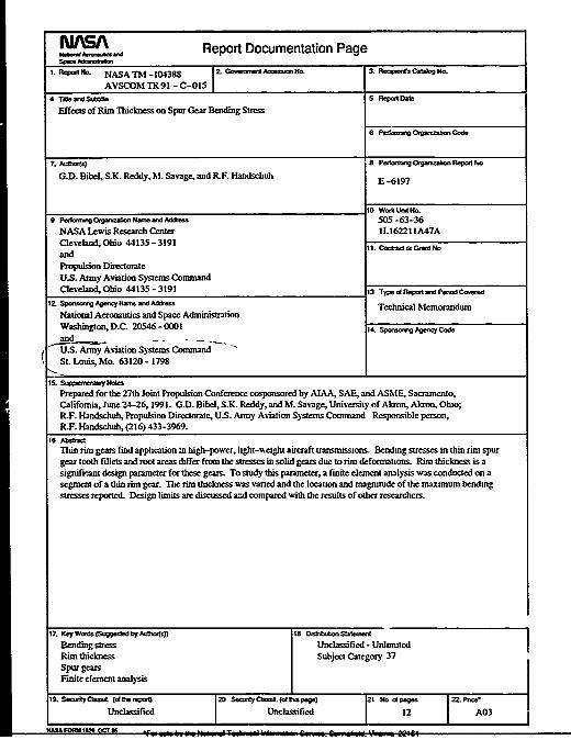
Thin rim gears find application mn high-power, lhght-,eight aircraft transmissions. Bending stresses in thin rim spurgear tooth fillets and root areas differ from the stresses in solid geam due to rim deformations. Rim thickness is asignifisnt design parameter for these gears. To study this parameter, a finite element analysis %%as conducted on asegment of a thin run gear. The rim thickness was varied and the location and magnitude of the maximum bendingstresses reported. Design limits are discussed a-.d compared with the results of other researchers.
17. Ksy Woors (SuQ.Oled byk AUsTo)) 18 Dt OVbMSio-9ni
Bending stress Unclassified - UnlimitedRim thickness Subject Category 37Spur gearsFinite element analysis
19. smootycies& (*idfed Un4= c assifi (I e id peg.) 2 P2oeA
Unclassified Unclassified 12 A03
" i~11111National Aeronautics and FOURTH CLASS MAIL I ISpace Administration
Lewis Research Center ADDRESS CORRECTION REQUESTEOCleveland, Ohio 44135
NASA