Embed Size (px)
Citation preview

1
Spring Technical Meeting of the Central States Section of the Combustion Institute
April 22–24, 2012
Effect of von Kármán vortex shedding on regular and open-slit V-gutter stabilized turbulent premixed flames
Alejandro M. Briones1 and Balu Sekar2
1University of Dayton Research Institute, Dayton, OH, USA
2AFRL/RZTC, Wright-Patterson AFB, Dayton, OH, USA
The commercial code FLUENT is used for modeling and simulation of three- and two-
dimensional non-reacting and reacting flows past regular and open-slit V-gutters. Incompressible Large-Eddy Simulations with Dynamic Subgrid Kinetic Energy Model, C-progress variable equation and Zimont turbulent flame speed closure are used. C3H8 is used as the fuel. The measured and predicted time-averaged streamwise velocity and r.m.s velocity are qualitatively similar for both three- and two-dimensional regular V-gutters under non-reacting conditions. However, the two-dimensional geometry predicts a longer recirculation zone, but shifted upstream. The two-dimensional geometry overpredicts the turbulence fluctuation downstream the flameholder, whereas the three-dimensional geometry underpredicts it. The two-dimensional geometry exhibits greater drag coefficient (CD) per unit flameholder width than that of the corresponding three-dimensional geometry. However, the Strouhal numbers (St) for both geometries are similar. In contrast to the two-dimensional regular V-gutter, the two-dimensional open-slit V-gutter contains no recirculation zone, it is likely dominated by shear layer instability, and exhibits a reduced drag coefficient (CD) (i.e., 29% reduction). The two-dimensional, stoichiometric turbulent premixed flame anchored to the tip of the regular V-gutter exhibits a shear layer immediately downstream the flameholder, and further downstream vortex shedding is pronounced. On the other hand, the flame attached to the open-slit V-gutter does not shed large vortices. This flame is attached to the flameholder boundary layers as well as on the flameholder leading edges. It also contains a jet-like reaction zone due to the slit. The stoichiometric flame attached to the open-slit V-gutter appears to be dynamically stable compared to that attached to the regular V-gutter flameholder. With drastic reductions in equivalence ratio ( the flame structures change dramatically in both flameholders. Both flame lengths shrink and large scale disruptions occur downstream with vortex shedding carrying reaction zones. Flames in both flameholders do not attach when Finally, based on product formation rate (SC) and vorticity (3) contours, spectral analysis, and standard Rayleigh index, a trade-off between static and dynamic stability is evident.
1. Introduction
Requirements for rapid increase in thrust for take-off and climb calls for additional thrust producing devices. The after-burner concept is an auxiliary burner located behind the turbine section and forward of the exhaust nozzle that operates by injecting fuel to the hot exhaust

Report Documentation Page Form ApprovedOMB No. 0704-0188
Public reporting burden for the collection of information is estimated to average 1 hour per response, including the time for reviewing instructions, searching existing data sources, gathering andmaintaining the data needed, and completing and reviewing the collection of information. Send comments regarding this burden estimate or any other aspect of this collection of information,including suggestions for reducing this burden, to Washington Headquarters Services, Directorate for Information Operations and Reports, 1215 Jefferson Davis Highway, Suite 1204, ArlingtonVA 22202-4302. Respondents should be aware that notwithstanding any other provision of law, no person shall be subject to a penalty for failing to comply with a collection of information if itdoes not display a currently valid OMB control number.
1. REPORT DATE APR 2012 2. REPORT TYPE
3. DATES COVERED 00-00-2012 to 00-00-2012
4. TITLE AND SUBTITLE Effect Of Von Karman Vortex Shedding On Regular And Open-slitV-gutter Stabilized Turbulent Premixed Flames
5a. CONTRACT NUMBER
5b. GRANT NUMBER
5c. PROGRAM ELEMENT NUMBER
6. AUTHOR(S) 5d. PROJECT NUMBER
5e. TASK NUMBER
5f. WORK UNIT NUMBER
7. PERFORMING ORGANIZATION NAME(S) AND ADDRESS(ES) AFRL/RZTC,Wright-Patterson AFB,Dayton,OH,45433
8. PERFORMING ORGANIZATIONREPORT NUMBER
9. SPONSORING/MONITORING AGENCY NAME(S) AND ADDRESS(ES) 10. SPONSOR/MONITOR’S ACRONYM(S)
11. SPONSOR/MONITOR’S REPORT NUMBER(S)
12. DISTRIBUTION/AVAILABILITY STATEMENT Approved for public release; distribution unlimited
13. SUPPLEMENTARY NOTES
14. ABSTRACT The commercial code FLUENT is used for modeling and simulation of three- and twodimensionalnon-reacting and reacting flows past regular and open-slit V-gutters. Incompressible Large-EddySimulations with Dynamic Subgrid Kinetic Energy Model, C-progress variable equation and Zimontturbulent flame speed closure are used. C3H8 is used as the fuel. The measured and predictedtime-averaged streamwise velocity and r.m.s velocity are qualitatively similar for both three- andtwo-dimensional regular V-gutters under non-reacting conditions.However, the two-dimensional geometrypredicts a longer recirculation zone, but shifted upstream. The two-dimensional geometry overpredicts theturbulence fluctuation downstream the flameholder, whereas the three-dimensional geometryunderpredicts it. The two-dimensional geometry exhibits greater drag coefficient (CD) per unitflameholder width than that of the corresponding three-dimensional geometry. However, the Strouhalnumbers (St) for both geometries are similar.
15. SUBJECT TERMS
16. SECURITY CLASSIFICATION OF: 17. LIMITATION OF ABSTRACT Same as
Report (SAR)
18. NUMBEROF PAGES
20
19a. NAME OFRESPONSIBLE PERSON
a. REPORT unclassified
b. ABSTRACT unclassified
c. THIS PAGE unclassified
Standard Form 298 (Rev. 8-98) Prescribed by ANSI Std Z39-18

2
leading to further combustion and extra thrust. Thus, this additional thrust producing device provides the demanded extra thrust for these aircraft operations for short durations without significant penalties in weight and engine complexity [1]. The thrust capability of an engine may be augmented by an additional 50-100% for short duration to meet these aircraft operation requirements [1]. However, the specific fuel consumption and associated noise during augmentation is substantially higher than that achieved during non-augmented operation. Therefore, augmentation is used cautiously in military operations. Despite the disadvantages previously mentioned, augmentation is attractive for meeting thrust requirements for high-speed applications.
In a combustor system, a typical afterburner operation is described as follows. The liquid fuel is injected through spray bars and is atomized by shearing due to the turbine exhaust flow. It then evaporates and mixes with the available oxygen. The mixture is ignited by a pilot flame creating a combustion region. The flames are typically stabilized using an array of bluff body flameholders, which are arranged in a single plane perpendicular to the flow direction and spaced either regularly or irregularly in either lateral dimension. The flameholders provide robust fluid recirculation zones that allow turbulent flames to uniformly attached and spread across the duct. The combustion products exit through a converging/diverging nozzle with extensive film cooling and a variable throat area located downstream of the afterburner exit. The afterburner may experience two types of instabilities: static and dynamic. The static stability refers to the ability of the flameholders to sustain a flame without blowing out. The dynamic stability refers to the unsteady character of the flame and often occurs at discrete frequencies spontaneously excited by feedback between the unsteady heat release rate and generally one of the natural acoustic modes of the combustor. The high frequency dynamic (combustion) instability (i.e., 120 – 600 Hz) is named screech and is attributed to a combination of factors including flameholder geometry, fuel spray injection sites, blockage, non-uniformity of fuel/air ratio, evaporation rates, and ignition process. A canister liner is typically used in afterburners to reduce screech in order to avoid deterioration and failure of the engine. The low frequency dynamic instability (i.e., 50 – 120 Hz) is named rumble and is coupled with the fuel and air supplies and its interaction with the unsteady flow field. Due to the destructive nature of dynamic instabilities and the undesirable blowout phenomenon during flight operations, considerable efforts from engine manufactures are oriented to understand these phenomena for further reduction and suppression.
Static instability or blowout is particularly a major challenge at flow conditions for modern aircraft afterburner. The flames need to remain anchored to a flameholder under highly vitiated, lean fuel-air mixture, and high-speed flow. The fundamental understanding of the physical mechanism that leads to blowout is critical to avoid this phenomenon from happening and to develop advanced flameholders. Understanding blowout in an afterbuner is extremely difficult and unpractical because the combustion environment in such device involves many complex physical processes, such as liquid fuel injection, atomization, vaporization, molecular mixing, and turbulence-chemistry interactions. Therefore, insight into the fundamental mechanisms responsible for afterburner’s static instability can be obtained from single flameholder studies with pre-vaporized fuel and premixed mixture in order to isolate the turbulence-chemistry interactions from the complex physical processes. The basic structure of the flow field generated by a flameholder in non-reacting and reacting conditions is well known. The flameholder generates a flow field composed by boundary layers, separated shear layers, and a wake [2]. There are two hydrodynamic instabilities associated with the shear layer and wake. The shear layer or Kelvin-Helmholtz (KH) instability is a convective instability related to the amplification

3
of disturbances, leading to vortex roll-up and symmetric paring of the separated shear layers. The wake or Bérnárd/von Kármán (BvK) instability leads to an asymmetric shedding of vortices from opposite side of the flameholder and sinuous wake structure.
There are many studies on the static instability of bluff body stabilized flames. Longwell et al. [3] and Ballal and Lefebvre [4,5] described the static instability (blowout) phenomenon via perfectly stirred reactor instability theory and showed that blowout occurs when the heat release rate in the wake region becomes insufficient to heat the incoming unburned mixture. On the other hand, Sukoski and Marble [6] established the blowout mechanism in terms of characteristic ignition time of unburned fuel/oxidant mixture in the bluff body generated shear layer. In this theory, an unburned fuel/air mixture passes over the bluff body and mixes with hot products and is ignited in the shear layer that lies between the recirculation zone and the free stream. The flame blows out when the residence time of the fresh mixture in the free shear layer becomes smaller than that of the characteristics ignition delay time. Recently, Lieuwen and coworkers [7,8] concluded that blowout occurs in multiple steps including local extinction along the flame sheet, large scale wake disruption, and a final blowout whose ultimate trigger is associated with wake cooling and shrinking. Moreover, there is a vast literature that has reported that a flame near blowout transitions from KH-instability dominated flow field to BvK instability [8,9,10,11]. In addition, Erickson et al. [10] suggested that the asymmetrical von Kármán vortex shedding plays a dominant role in the blowout mechanism of bluff body stabilized premixed flames since it is the dominant mode as Tb/Tu approaches values close to blowout conditions (i.e., ~ 1.5). The measurements of Nair and Lieuwen [8] and Kiel et al. [11] further corroborated the numerical results of Erickson et al. [10]. However, they predicted higher Tb/Tu transition values from KH to BvK instability (i.e., Tb/Tu~5-6 [8] and ~2.7 [11]). Lieuwen and coworkers [8,12] suggested that the lower Tb/Tu reported by Erickson et al. [10] may be because in their numerical simulations there was no extinction. Similarly, several investigations [8,13,14] have shown that by reducing the equivalence ratio () for bluff body stabilized flames the flow field transitions from KH to BvK instability dominated flow. This transition from a symmetric flow characteristic of the KH instability to an asymmetric undulated wake typical of BvK instability is not fully understood. For instance, some investigations suggest that the baroclinic torque [15,16], gas expansion [17], and enhanced vortex diffusion [18] responsible for suppression of BvK instability in flames is diminished at nearly blowout and non-reacting conditions, leading to BvK instability. It is not clear from the literature which mechanism is responsible for blowout. Furthermore, Khosla et al. [13] studied the role of von Kármán vortex shedding on flame blowout by comparing the lean blowout limit between a bluff body that exhibits von Kármán vortex shedding with that that inhibits vortex shedding under non-reacting conditions. In contradiction with previous work [9-11], their results demonstrated that von Kármán vortex shedding might not play a role in blowout since both flames globally extinguished at the same . Although static instability has been investigated in the past and there is general agreement that the blowout process is controlled by a competition between fluid mechanical and chemical kinetic processes there is still need to fully understand in detail the latter processes that ultimately lead to flame blowout. Therefore, further understanding of the flow field behind these flameholders is of great importance to design stable afterburners free of static combustion instability.
Among the several shapes of bluff bodies available to stabilize a turbulent premixed flame, the V-gutter is outstanding in aircraft afterburners. Therefore, it is important to study the role of von Kármán vortex shedding on blowout of flames anchored in this flameholder. The V-gutter sheds von Kármán vortices at non-reacting and near blowout conditions [19]. Therefore, we

4
follow similar procedure to that by Khosla et al. [13] to study the role of von Kármán vortex shedding on flame blowout. In their investigation they used tabs on a rectangular-like flameholder with rounded front surface in order to restrain von Kármán vortex shedding. We waned vortex shedding by splitting the V-gutter. This open-slit V-gutter is used because it has been previously shown that it favors flameholding mechanism and the suppression of flow-induced oscillations [20,21]. In addition, the open-slit V-gutter would reduce the total weight of the afterburner.
The purpose of our investigation is to shed light into the ongoing research on blowout for bluff body stabilized turbulent premixed flames. The specific objectives are to: 1) compare the two-dimensional results in non-reacting conditions with those obtained in a three-dimensional configuration in terms of Strouhal number (St), drag coefficient (CD), and wake velocity profiles; (2) examine the differences between the regular and open-slit V-gutter in non-reacting and reacting conditions in the two-dimensional geometry; (3) study the lean blowout limit of both regular and open-slit V-gutter; and (4) provide initial insights on the dynamic thermoacoustic (combustion) instabilities by means of spectral analysis and standard Rayleigh index. The first objective is used to provide an indication of the amount and type of information being lost when modeling in two-dimensional geometry. In fact, the two-dimensional modeling is accomplished by reducing the width of the spanwise direction to a single cell. Therefore, the three-dimensional governing equations are still being solved for all simulations. The spanwise wall boundary conditions are replaced by translational periodic boundary conditions. In order to cut down the computational time all calculations are pseudo two-dimensional unless otherwise specified.
2. Physical-Numerical Procedure
In this section we discuss the physical model, subgrid-scale model, turbulent flame speed model, geometry, mesh, boundary conditions, and parallel computations.
2.1 Numerical Model
The three-dimensional Large Eddy Simulation (LES) governing equations of continuity, momentum, subgrid-scale turbulent kinetic energy, and C-progress variable equations are solved using SIMPLEC solver of FLUENT [22]. The Standard k- RANS is used to initialize the flow for the LES. The governing equations are spatially and temporally second-order accurate. The three-dimensional incompressible LES governing equations in tensor notation and conservative form are presented below:
Continuity Equation
0
Momentum Equations
μ μ
Dynamic Sub-grid Kinetic Energy Equation
τ C/
∆

5
τ ρk δ C k / ∆
C-Progress Variable Equation
ρS
The turbulent viscosity (t) is obtained from μ C k / ∆ , where ∆ V / [23]. The
constants Ck and Care obtained dynamically using the resolved velocity as suggested in Ref. 23. The turbulent Schmidt number (Sct) is obtained by applying the dynamic procedure proposed by Germano [24].
2.2 Turbulent flame speed Closure
The Zimont turbulent speed closure for LES is used to model the wrinkled and thickened flame [25]. The model is given as follows.
U A A u ⁄ U ⁄ α ⁄ l ⁄
l C Δ , u l τ , S
τ 2S S⁄
ρS ρ U⁄
The values used for the constants are A=0.52, Astr=0.26, and Aw=0.1. Aw is the damping
factor at the walls, otherwise Aw=1. The physical properties used are those of air at ambient conditions (i.e., =2.25×10⁻⁵ m2/s, =2.25×10⁻⁵ kg-m/s, and u=1.225 kg/m3).
2.3 Temperature and Density
The temperature (T) and density () are assumed to be a linear variation of the progress variable (c) (i.e., T 1 c T cT , 1 c ρ cρ , where bTad uTu). The value of the unburned temperature is Tu=293.15 K.
2.4 Geometry and Mesh
A schematic of the computational domains with the boundary conditions used for the simulations are presented in Figure 1. Typical mesh used for modeling and simulation are shown in Figure 2. Hexahedral cells are used throughout the computational domain. The effect of mesh size on numerical results has been conducted to show that this grid size satisfactorily resolves the flow field. The non-uniform-structured mesh stretch factor never exceeds 1.2. The model resolves the laminar sub-layer if the mesh is fine enough using the stress-strain relationship and models the logarithmic boundary layer if the mesh is too coarse using the law-of-the-wall [22]. If the centroid of the wall-adjacent cell falls in the buffer region, the blending method suggested by Kadar is used [26].
6
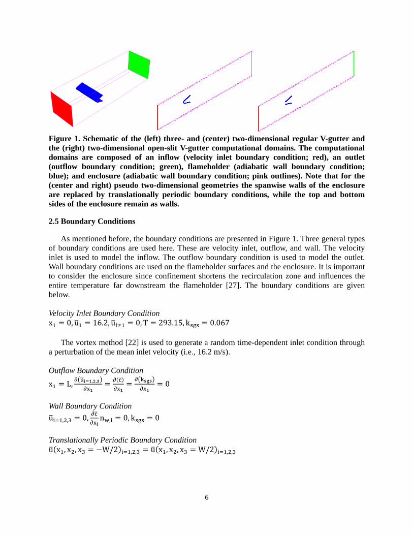
Figure 1. Schematic of the (left) three- and (center) two-dimensional regular V-gutter and the (right) two-dimensional open-slit V-gutter computational domains. The computational domains are composed of an inflow (velocity inlet boundary condition; red), an outlet (outflow boundary condition; green), flameholder (adiabatic wall boundary condition; blue); and enclosure (adiabatic wall boundary condition; pink outlines). Note that for the (center and right) pseudo two-dimensional geometries the spanwise walls of the enclosure are replaced by translationally periodic boundary conditions, while the top and bottom sides of the enclosure remain as walls.
2.5 Boundary Conditions
As mentioned before, the boundary conditions are presented in Figure 1. Three general types of boundary conditions are used here. These are velocity inlet, outflow, and wall. The velocity inlet is used to model the inflow. The outflow boundary condition is used to model the outlet. Wall boundary conditions are used on the flameholder surfaces and the enclosure. It is important to consider the enclosure since confinement shortens the recirculation zone and influences the entire temperature far downstream the flameholder [27]. The boundary conditions are given below.
Velocity Inlet Boundary Condition x 0, u 16.2, u 0, T 293.15, k 0.067
The vortex method [22] is used to generate a random time-dependent inlet condition through
a perturbation of the mean inlet velocity (i.e., 16.2 m/s).
Outflow Boundary Condition
x L, , , 0
Wall Boundary Condition
u , , 0, n , 0, k 0
Translationally Periodic Boundary Condition u x , x , x W/2 , , u x , x , x W/2 , ,

7
Table 1. Operating conditions.
1.0 0.6 0.5 0.45 0.0
(cm/s) 44 13 4.5 0.25 0
(K) 2390 1702 1509 1407 294.3
Figure 2. Cross-sectional area of the computational domains at centerplane (z = 0) illustrating the hexahedral mesh for the regular and open-slit V-gutter flameholders discussed in the context of Figure 1.
2.6 Parallel Computations
The simulations are conducted in the Hawk supercomputer of the DoD Supercomputing Resource Center (DSRC) system at the Air Force Research Laboratory (AFRL) and the RZT cluster of the Propulsion Directorate. The Hawk SGI Altix 4700 supercomputer with 96 cores (Dual-core 1.6 GHz Itanium 2 processors) is used for the calculation of the three-dimensional non-reacting flow of the regular V-gutter. The RZT cluster is used for the pseudo two-dimensional calculations with 4 cores (Dual-core 2.80 GHz AMD Opteron processors). The time step used is 10 s.
3. Results and Discussion
3.1 Operating Conditions
Table 1 presents the operating conditions for the V-gutter presented in Figure 1. Note that =0.0 represents the non-reacting condition. In fact, the non-reacting condition does not solve for the progress variable equation. The unstretched laminar flame speeds (Ul) were obtained from propane-air measurements [28]; and the adiabatic temperature (Tad) is based on equilibrium calculations of propane-air mixtures. For all conditions ReH=45,500 and the operating pressure is 101,325 Pa.
3.2 Comparison between the Three-dimensional and Pseudo Two-dimensional Regular V-gutter: Non-reacting Flow
Figure 3 presents the measured [11] and predicted streamwise velocity Avg(u u ,⁄ ) and RMS(u u ,⁄ ) as a function of dimensionless streamwise
position (x1`/H) for the three- and two-dimensional regular V-gutters. The experiment reveals that Avg(u u ,⁄ ) rapidly decreases downstream the flameholder until it reaches a minimum (i.e., Avg(u u ,⁄ )=0.65 at x1`/H=0.61). Then, the measured Avg(u u ,⁄ ) swiftly increases until x1`/H3.0 and after that Avg(u u ,⁄ ) increases gradually to approach the free stream value as the recirculation flow region induced by the bluff body disappears. The numerical simulations exhibit identical profiles ahead of the flameholder. The three-dimensional model suggests that the flow velocity increases immediately downstream the inner walls of the flameholder until it reaches a local maximum and then it decreases to a local minimum (i.e., Avg(u u ,⁄ )=0.58 at x1`/H=0.85). For the two-dimensional model this local minimum is shifted towards the
x1` x2`
x1 x2
x1`x2`x1
x2

8
flameholder with a more pronounced reverse flow (i.e., Avg(u u ,⁄ )=1.0 at x1`/H=0.10). Interestingly, Giacomazzi et al. [27] stated that an effect of assuming translationally periodic boundary conditions in the spanwise direction instead of capturing the side walls effect is to lengthen the recirculation zone. Therefore, the aforementioned statement is apparently in contradiction with the current results. However, the results in Figure 3 shows that the recirculation zone length of the two-dimensional geometry (i.e., 2 H) is longer than that of the three-dimensional geometry (i.e., 1.4 H), measured as the difference between the two locations of the zero streamwise velocities adjacent to the global minimum streamwise velocity. The recirculation zone is, nevertheless, shifted towards the inside of the V-gutter for the two-dimensional geometry in comparison with that of the three-dimensional geometry. The measured RMS(u u ,⁄ ) increases very rapidly downstream the V-gutter until it reaches a maximum downstream the flameholder at x1`/H 0.6 and then the RMS(u u ,⁄ ) decreases further downstream. The three-dimensional model underpredicts the measured RMS(u u ,⁄ ), whereas the two-dimensional model overpredicts it. Therefore, the two-dimensional model indicates a higher degree of turbulence downstream the flameholder. In summary, the measured and predicted Avg(u u ,⁄ ) and RMS(u u ,⁄ ) are qualitatively similar; however, the two-dimensional model predicts an upstream shifted, but longer recirculation zone (due to lack of vortex stretching and of side wall boundary layer, respectively) with higher turbulence downstream the flameholder when compared with measurements and the three-dimensional model predictions.
Figure 3. Measured [11] and predicted dimensionless averaged streamwise velocity Avg( ,⁄ ) and RMS( ,⁄ ) as a function of dimensionless streamwise position (x1`/H) for the (solid red lines) three-dimensional and (solid green lines) two-dimensional regular V-gutters.
It was previously shown [29] that the averaged drag (CD) and lift (CL) coefficients are 0.45 and 0.0, respectively, for the three-dimensional model. For the two-dimensional model the averaged drag (CD) and lift (CL) coefficients are 0.017 and 0.0, respectively. Clearly, the reduction in CD is due to the fact the flameholder width contributes to drag and that the translationally periodic boundary conditions cannot account for it. In fact, the two-dimensional geometry is 1/38 of the three-dimensional geometry. This suggests that CD for the two-
x1'/H
Av
g(u
1/u
1,0)
-4 -2 0 2 4 6 8 10-2
-1
0
1
2
Kiel et al.Three-Dimensional GeometryTwo-Dimensional Geometry
Regular V-gutter
x1'/H
RM
S(u
1/u
1,0)
-4 -2 0 2 4 6 8 100
0.2
0.4
0.6
0.8
1

9
dimensional geometry should be 38 × 0.0170.646 Therefore, the two-dimensional geometry with translationally periodic boundary conditions predicts greater CD than the three-dimensional geometry due to the lack of side wall boundary layers, which would have diminished the static pressure just upstream the flameholder. That is, the side walls would have taken a share of the drag force. In addition, the associated von Kármán Strouhal number (St) is 0.3 [29] and 0.26 for the three-dimensional and two-dimensional geometries, respectively. The differences in St might be due to the lack of vortex stretching in the two-dimensional geometry.
3.3 Pseudo Two-dimensional Regular and Open-Slit V-gutters: Non-reacting Flow
Figure 4 illustrates the averaged streamwise velocity Avg(u u ,⁄ ) and RMS(u u ,⁄ ) as a function of dimensionless streamwise position (x1`/H) for the regular and open-slit V-gutter. The profiles of the two-dimensional regular V-gutter were discussed in the previous section. The open-slit V-gutter shows that the flow just ahead of it slightly decreases and when it passes through the slit it abruptly increases until it reaches a global maximum Avg(u u ,⁄ ) and RMS(u u ,⁄ ). Then, Avg(u u ,⁄ ) and RMS(u u ,⁄ ) decrease abruptly towards the trailing edges of the flameholder and the former profile reaches a global minimum. Further downstream Avg(u u ,⁄ ) increases somewhat rapidly but not as fast as that of the regular V-gutter, while RMS(u u ,⁄ ) slightly decreases with values below that exhibited by the regular V-gutter. There are major differences between the flow fields generated by the regular and open-slit V-gutters such as the absence of a recirculation zone by the latter flameholder.
Figure 4. Predicted dimensionless averaged streamwise velocity Avg( ,⁄ ) and RMS( ,⁄ ) as a function of dimensionless streamwise position (x1`/H) for the (solid lines) regular V-gutter and (dash lines) open-slit V-gutter.
Figure 5 and Figure 6 present the temporal drag (CD) and lift (CL) coefficients, respectively, for the two-dimensional flameholders under investigation. Clearly, the regular V-gutter exhibits larger amplitudes of oscillation than the open-slit V-gutter. The averaged CD is 0.017 and 0.012 for the regular and open-slit V-gutters, respectively. The latter flameholder exhibits lower CD due to reduction on the total area exposed to the upstream flow. Although the magnitudes of CD are
x1'/H
Av
g(u
1/u
1,0)
-4 -2 0 2 4 6 8 10-2
-1.5
-1
-0.5
0
0.5
1
1.5
2
Regular V-gutterOpen-slit V-gutter
x1'/H
RM
S(u
1/u
1,0)
-4 -2 0 2 4 6 8 100
0.2
0.4
0.6
0.8
1

10
small due to the pseudo two-dimensional geometry as discussed in the previous section, the reduction with the open-slit V-gutter is of 29%.
Figure 5. Temporal drag coefficient (CD) for the (left) regular and (right) open-slit V-gutter.
Figure 6. Temporal lift coefficient (CL) for the (left) regular and (right) open-slit V-gutter.
Figure 7 illustrates the lift coefficient (CL) amplitude as a function of Strouhal number (St) for both the regular and open-slit V-gutters. The regular V-gutter shows a dominant peak at St = 0.26, typical of the von Kármán vortex street. For the open-slit V-gutter there is no dominant peak on its CL amplitude spectrum. This suggests that there are significant differences between the key flow features of the regular and open-slit V-gutter. The open-slit V-gutter is likely dominated by shear layer fluctuations, instead of wake fluctuations.
3.4 Lean Blowout Limits of the Regular and Open-slit V-gutter: Reacting Flow
t (ms)
CD
0 100 200 300 400-0.2
-0.1
0
0.1
0.2
Regular V-gutter
t (ms)C
D
0 100 200 300 400-0.2
-0.1
0
0.1
0.2
Open-slit V-gutter
t (ms)
CL
0 100 200 300 400-0.04
-0.02
0
0.02
0.04Regular V-gutter
t (ms)
CL
0 100 200 300 400-0.04
-0.02
0
0.02
0.04Open-slit V-gutter

11
St
CL
Am
plit
ud
e
10-1 100 1010
0.001
0.002
0.003
0.004
Regular V-gutterOpen-slit V-gutter
Figure 7. Lift coefficient amplitude (CL) as a function of Strouhal number (St) for both the regular and open-slit V-gutters.
Since it became clear in the previous section that the regular and open-slit V-gutter exhibit different flow fields, the lean blowout limits of these two flameholders were examined by establishing turbulent premixed flames at and at Turbulent flames were individually simulated at and At turbulent premixed flames blew out in both flameholders. However, for the open-slit V-gutter the turbulent premixed flame blew out almost immediately, whereas for the regular V-gutter a turbulent premixed flame was firstly attached to the flameholder. After 70 ms the flame’s product formation rate (SC) dropped and the flame blew out. This suggests, contrary to our expectations that the regular V-gutter performs slightly better than that of the open-slit V-gutter in terms of static stability
(i.e., the flame attached to the open-slit V-gutter blows out at slightly greater ). Yang et al. [21] showed that the open-slit V-gutter extends the static stability limits when the slit is less than 26 % the V-gutter trailing edge aperture. For the current condition, the aperture is 32 % the flameholder trailing edge aperture.
The events leading to static instability can be studied by plotting the product formation rate (SC) and spanwise vorticity (3) contours for the turbulent premixed flames established at and in Figure 8, Figure 9, and Figure 10, respectively. At shear layer dominates immediately downstream (x1`<2H) and further downstream vortex shedding is somewhat pronounced for the regular V-gutter. Similarly, in our previous investigation [29], it was shown that vortex shedding is diminished for the reacting flow established at in a three-dimensional geometry. The major difference between the current pseudo two-dimensional geometry and the previous three-dimensional geometry [29] is that in the former the flame is attached to the leading edge of the flameholder, whereas for the latter the flame is attached to the trailing edges of the flameholder. The maximum SC and turbulent flame speed (Ut) occur at the flameholder leading edge for the current simulation. Differences in the attachment location might be due to the lack of 1) vortex stretching, and/or 2) local quenching mechanism [29]. The turbulent premixed flame attached to the open-slit V-gutter, on the other hand, does not shed large vortices. However, vortices are comprised in between reaction zones. This flame is attached to the flameholder’s boundary layers and leading edges. It also exhibits a jet-like reaction region due to the slit. While the amplitude of oscillation is large for the regular V-gutter that of the open-slit V-gutter is less pronounced. This might indicate improved dynamic stability for the latter flameholder.
By reducing from 1.0 to 0.6 (cf. Figure 9) the flame structure changes dramatically for both regular and open-slit V-gutter. Both flame lengths shrink and large scale disruptions occur downstream. These flames shed vortices containing islands of reaction zones. Both flames are now attached to the trailing edges of the flameholder. Note that the open-slit V-gutter stabilized flame is also attached to the leading edges of the flameholder. Further reduction in to 0.5,

12
further reduces the flame length. However, qualitatively the open-slit V-gutter appears to be more sensitive than the regular V-gutter. Both flames remain shedding vortices. Therefore, the blowout processed is definitely characterized by large scale disruptions with vortices transporting reaction zones away from the flames.
Figure 8. Product formation rate contours (Sc) (rainbow color scheme) and spanwise vorticity (3) contours (black lines) for both regular and open-slit V-gutter. The equivalence ratio () is 1.0. The units of SC are in s-1.
In our previous investigation [29] it was shown that by decreasing the recirculation zone of the (three-dimensional) regular V-gutter moves upstream until blowout occurs. According to Figure 11, which presents the Avg(u u ,⁄ ) as a function of dimensionless streamwise position (x1`/H), the recirculation zone moves downstream, while the magnitude of the reverse flow decreases. Therefore, the blowout mechanisms for two- and three-dimensional geometries are somewhat different. For the open-slit V-gutter, the maximum flow velocity magnitude and location is not substantially affected regardless of , but the flow downstream the flame slows down due to reduced thermal expansion. Figure 12 illustrates the corresponding RMS(u u ,⁄ ) as a function of dimensionless streamwise position (x1`/H) for the regular and open-slit V-gutters. Previously [29], it was shown that by decreasing turbulence fluctuations decrease for (three-dimensional) regular V-gutter. In contrast, the turbulence fluctuations increase with decreasing for the (two-dimensional) regular V-gutter. For the open-slit V-gutter turbulence fluctuations increase at locations where large scale disruptions occur and decrease at locations where the flame is present. Therefore, the blowout mechanism is not similar for both flameholders and large scale disruption with transport of reaction zones away from the flames appear to be a universal feature of flame blowout.

13
Figure 9. Product formation rate contours (Sc) (rainbow color scheme) and spanwise vorticity (3) contours (black lines) for both regular and open-slit V-gutter. The equivalence ratio () is 0.6. Same legend as that shown in Figure 8 is used. The units of SC are in s-1.
Figure 10. Product formation rate (Sc) (rainbow color scheme) and spanwise vorticity (3) contours (black lines) for both regular and open-slit V-gutter. The equivalence ratio () is 0.5. Same legend as that shown in Figure 8 is used. The units of SC are in s-1.

14
Figure 11. Predicted dimensionless averaged streamwise velocity Avg( ,⁄ ) as a function of dimensionless streamwise position (x1`/H) for the (left) regular V-gutter and (right) open-slit V-gutter stabilized turbulent premixed flames established at equivalence ratios (red solid line) of =1.0, (green dashed line) =0.6, and (blue dashed-dot line) =0.5.
Figure 12. Predicted dimensionless averaged streamwise RMS( ,⁄ ) as a function of dimensionless streamwise position (x1`/H) for (left) regular and (right) open-slit V-gutter stabilized turbulent premixed flames established at equivalence ratios (red solid line) of =1.0, (green dashed line) =0.6, and (blue dashed-dot line) =0.5.
Table 2 shows the drag coefficients (CD) for the regular and open-slit V-gutter as a function of With decreasing , CD decreases for the regular V-gutter, whereas it remains nearly constant for the open-slit V-gutter. As discussed in a previous section, CD is 0.017 and 0.012 for the regular and open-slit V-gutters, respectively. This indicates that CD for the open-slit V-gutter should increase near blowout. This, in turn, suggests that CD for the regular V-gutter is more sensitive to than the open-slit V-gutter. In addition, both flameholders experience same drag force at maximum adiabatic flame temperature (i.e. =1.0).
x1'/H
Av
g(u
1/u
1,0)
-4 -2 0 2 4 6 8 10
-2
0
2
4
= 1.0 = 0.6 = 0.5
x1'/H
Av
g(u
1/u
1,0)
-4 -2 0 2 4 6 8 10
-2
0
2
4
= 1.0 = 0.6 = 0.5
x1'/H
RM
S(u
1/u
1,0)
-4 -2 0 2 4 6 8 100
2
4
6
8
10
12
= 1.0 = 0.6 = 0.5
x1'/H
RM
S(u
1,0/u
1)
-4 -2 0 2 4 6 8 100
0.2
0.4
0.6
0.8
1
= 1.0 = 0.6 = 0.5

15
St
CL
Am
plit
ud
e
10-2 10-1 100 101 1020
5E-05
0.0001
0.00015
0.0002
Regular V-gutterOpen-slit V-gutter
= 0.5
Table 2. Drag coefficient (CD) for the regular and open-slit V-gutter as a function of equivalence ratio ().
Regular V-gutter Open-slit V-gutter 1.0 0.0073 0.0076
0.6 0.0107 0.0064
0.5 0.0110 0.0068
Figure 13 presents the lift coefficient (CL) amplitude as a function of Strouhal number (St) for the regular and open-slit V-gutter stabilized turbulent premixed flames established at equivalence ratios of and Both flames show that the maximum amplitude of CL decreases with Nonetheless, Figure 7 shows that for these flameholders under
non-reacting conditions (i.e., =0.0) the maximum amplitude of CL is larger than that of This indicates that right after blowout occurs the amplitude of CL must increase again in order to match that of the non-reacting condition. At the turbulent premixed flame is shedding vortices (cf. Figure 8) at a discrete frequency (St = 0.32). Sub-harmonic frequencies are also present at this condition for this flameholder. On the contrary, the open-slit V-gutter is not shedding vortices and the flow is dominated by the shear layer instability characterized by very high frequencies (St >100). When drops the open-slit V-gutter starts to shed vortices and the flow becomes dominated by low frequencies (St = 0.062 for and St = 0.186 for ). The regular V-gutter always sheds vortices regardless of
Figure 13. Lift coefficient (CL) amplitude as a function of Strouhal number (St) for the regular and open-slit V-gutter stabilized turbulent premixed flames established at equivalence ratios of and
St
CL
Am
plit
ud
e
10-2 10-1 100 101 1020
0.0005
0.001
0.0015
0.002
Regular V-gutterOpen-slit V-gutter
= 1.0
St
CL
Am
plit
ud
e
10-2 10-1 100 101 1020
5E-05
0.0001
0.00015
0.0002
Regular V-gutterOpen-slit V-gutter
= 0.6

16
Typically, the thermoacoustic instabilities are measured using the standard Rayleigh index. This is the temporal-averaged and volume integral of the product of the pressure and heat release rate fluctuations. When the heat release rate oscillations are in phase with the pressure oscillations, the Rayleigh index is positive and the thermoacoustic instability grows. The converse is also true. Table 3 presents the Rayleigh index for the two flameholders as a function of This index is positive for both flameholders at and negative otherwise. Based on the magnitude of the Rayleigh index, this table indicates that the open-slit V-gutter is more dynamically (thermoacoutically) stable than the regular V-gutter at The converse is true for and . Towards blowout (or static instability) the Rayleigh index (i.e., thermoacoustic instability) decreases. Therefore, a trade-off between dynamic and static stability exists.
4. Concluding Remarks
Three- and two-dimensional non-reacting and two-dimensional reacting flows past a V-gutter are modeled using FLUENT. The three- and two-dimensional governing equations of continuity, momentum, turbulence, and C-progress variable are solved. Incompressible Large-Eddy Simulations with Dynamic Subgrid
Kinetic Energy Model are used for turbulence. The Zimont turbulent flame speed closure is used for the C-progress variable equation with physical-chemical properties of propane-air flames. The numerical results are validated with results reported in the literature. Important conclusions are as follows:
1. The measured and predicted time-averaged streamwise velocity and r.m.s velocity are qualitatively similar for both three- and two-dimensional regular V-gutters under non-reacting conditions. However, the two-dimensional geometry predicts a longer recirculation zone, but shifted upstream. It is believed that the length increment is due to the lack of vortex stretching, while the shift is due to the lack of side wall boundary layer. The two-dimensional geometry overpredicts the turbulence fluctuation downstream the flameholder, whereas the three-dimensional geometry underpredicts it. In addition, the two-dimensional geometry overpredicts the drag coefficient (CD) per unit flameholder width when compared to that of the three-dimensional geometry. However, the Strouhal numbers (St) for both geometries are not very different.
2. There are major differences between the flow fields generated by the regular and open-slit V-gutters under non-reacting conditions, such as the absence of a recirculation zone by the latter flameholder. The latter flameholder is likely dominated by shear layer instability and exhibits a reduction in the drag coefficient (CD) of 29 %.
3. The stoichiometric turbulent premixed flame anchored to the tip of the regular V-gutter exhibits a shear layer immediately downstream the flameholder and further downstream vortex shedding is somewhat pronounced. In contrast, the turbulent premixed flame attached to the open-slit V-gutter does not shed large vortices. Nonetheless, vortices are comprised in between the reaction zones. This flame is attached to the flameholder boundary layers as well as on the flameholder leading edges. It also exhibits a jet-like reaction zone due to the slit. The open-slit V-gutter appears to be more dynamically stable
Table 3. Standard Rayleigh index for the regular and open-slit V-gutter as a function of equivalence ratio ().
Regular V-gutter Open-slit V-gutter 1.0 16313 1734
0.6 624 2266
0.5 ‐645440 ‐1528

17
than the regular V-gutter flameholder as suggested by the product formation rate (SC) and vorticity (3) contour images, spectral analysis, and the standard Rayleigh index.
4. With drastic reductions of equivalence ratio ( the flame structure changes dramatically for both regular and open-slit V-gutter. Both flame lengths shrink and large scale disruptions occur downstream. These flames shed vortices containing reaction zones. Both flames attach to the flameholder trailing edges. The open-slit V-gutter stabilized flame is also attached to the flameholder leading edges. Further reduction in , additionally diminishes the flame length. Both flames continue shedding vortices. At the turbulent premixed flames blow out in both flameholders. However, for the open-slit V-gutter the turbulent premixed flame blows out almost immediately, whereas for that of the regular V-gutter a flame was firstly attached to the flameholder. This suggests that the regular V-gutter performs slightly better than that of the open-slit V-gutter in terms of static stability (i.e., the flame attached to the open-slit V-gutter blows out at slightly greater fuel-lean ).
5. By reducing from stoichiometry, the static stability is threatened and the turbulent premixed flame might blowout (i.e., static instability). Simultaneously, the reduction in decreases the standard Rayleigh index (i.e., thermoacoustic instability) from positive to negative, indicating a switch from thermoacoustic instability to stability. Therefore, a trade-off between static and dynamic stability is evident.
Acknowledgements
This material is based on the research sponsored by Air Force Research Laboratory under agreement number FA8650-10-2-2934. Acknowledgments are also expressed to DoD HPCMP office for providing the computational resources. The U.S. Government is authorized to reproduce and distribute reprints for Governmental purposes notwithstanding any copyright notation thereon. The views and conclusions contained herein are those of the authors and should not be interpreted as necessarily representing the official policies or endorsements, either expressed or implied, of Air Force Research Laboratory or the U.S. Government.
Nomenclature
A = turbulent length speed constant Aw = wall damping coefficient CD = drag coefficient = F 0.5⁄ u , Sinlet
Ck = model constant [kg/m] Cs = Smagorinsky constant C model constant [kg/m3] c = resolved progress variable f = primary frequency [1/s] H = outer width of V-gutter [m] L = length of channel [m] lt = turbulent length scale [m] ksgs = subgrid kinetic energy [J/kg] n = unit normal flame vector p = resolved (gauge) pressure [Pa]
ReH = Reynolds number = u , H⁄ Sinlet = inlet surface area [m2] S = strain rate tensor [1/s] Sc = progress variable source term [1/s] St = Strouhal number = fH u ,⁄ T = temperature [K] t = time [s] U = flame speed [m/s] V = cell volume [m3] W = flameholder width [m] u = resolved velocity vector [m/s] x = coordinate variable [m] Greek = density [kg/m3]
18
= turbulent dissipation rate [m2/s3] = equivalence ratio κ = resolved stretch rate [1/s] = dynamic viscosity [kg-m/s] = stress tensor [Pa] or standard deviation of distribution of k = model coefficient = stress tensor [Pa] = kinematic viscosity [m2/s] = vorticity vector [1/s2] Other f = cell characteristic length [m]
Superscript sgs = subgrid scale Subscript 0 = boundary condition ad = adiabatic b = burned cr = critical l = laminar sgs = subgrid scale n = normal t = turbulent u = unburned
References
1. Ebrahimi, H.B., “Overview of Gas Turbine Augmentor Design, Operation and Combustion Oscillation,” ILASS Americas, 19th Annual Conference on Liquid Atomization and Spray Systems, Toronto, Canada, May 2006. 2. Prasad, A., Williamson A., “The Instability of the Shear Layer Separating from a Bluff Body,” Journal of Fluid Mechanics, Vol. 333, 1997, 375-402. 3. Longwell, J. P., Chenevey, J., Clark, W., and Frost, E., “Flame Stabilization by Baffles in a High Velocity Gas Stream,” Proceedings of the Combustion Institute, Vol. 3, 1951, 40-44. 4. Ballal, D., and Lefebvre, A.H., “Weak Extinction Limits of Turbulent Flowing Mixtures,” ASME Journal of Engineering for Gas Turbines and Power, Vol. 101, No. 3, 1979, 343-348. 5. Ballal, D.R., Lefebvre, A.H., “Weak Extinction Limits of Turbulent Heterogeneous Fuel/Air Mixtures,” ASME Journal of Engineering for Gas Turbines and Power, Vol. 102, No. 2, 1980, 416-421. 6. Zuikoski, E.Z., and Marble, F.E., “Experiments Concerning the Mechanism of Flame Blowoff from Bluff Bodies,” Gas dynamic Symposium on Aerothermochemistry, Northwestern University, 1956, 205-210. 7. Shanbhogue, S.J., Husain, S., and Lieuwen, T., “Lean Blowoff of Bluff Body Stabilized Flames: Scaling and Dynamics,” Progress in Energy and Combustion Science, Vol. 35, 2009, 98-120. 8. Nair, S., and Lieuwen, T., “Near-Blowoff Dynamics of a Bluff-Body Stabilized Flame,” Journal of Propulsion and Power, Vol. 23, 2007, 421-427. 9. Mehta, P.G., and Soteriou, M.C., “Combustion Heat Release Effects on the Dynamics of Bluff Body Stabilized Premixed Reacting Flows,” 41st Aerospace Sciences Meeting and Exhibit, 6-9 January, Reno, NV, AIAA-2003-835. 10. Erickson, R.R., Soteriou M.C., and Mehta, P.G., “The Influence of Temperature Ratio on the Dynamics of Bluff Body Stabilized Flames,” 44th AIAA Aerospace Sciences Meeting and Exhibit, 2006, AIAA-2006-753. 11. Kiel, B., Garwick, K., Lynch, A., Gord, J.R., and Meyer, T., “Non-Reacting and Combusting Flow Investigation of Bluff Bodies in Cross Flow,” 42nd AIAA/ASME/SAE/ASEE Joint Propulsion Conference & Exhibit, 9-12 July, 2006, Sacramento, CA, AIAA-2006-5234.

19
12. Lieuwen, T., Shanghoque, S., Khosla, S., Smith, C., “Dynamics of Bluff Body Flame near Blowoff,” 45th AIAA Aerospace Sciences Meeting and Exhibit, 8-11 January 2007, Reno, NV, AIAA-2007-169. 13. Khosla, S., Leach, T. T., and Smith, C.E., “ Flame Stabilization and Role of von Karman Vortex Shedding behind Bluff Body Flameholders,” 43rd AIAA/ASME/SAE/ASEE Joint Propulsion Conference & Exhibit, 8-11 July, 2007, Cincinnati, OH, AIAA 2007-5653. 14. Smith, C. E., Nickolaus, D., Leach, T., Kiel, B., and Garwick, K., “LES Blowout Analysis of Premixed Flow Part V-Gutter Flameholder,” 45th AIAA Aerospace Sciences Meeting and Exhibit, 8-11 January, 2007, Reno, NV, AIAA-2007-170. 15. Ghoniem, A.F., Chorin, A.J., and Oppenheim, A.K., “Numerical Modeling of Turbulent Flow in a Combustion Channel,” Philosophical Transactions of the Royal Society of London A, Vol. 304, 1982, 303-325. 16. Soteriou, M.C., and Ghoniem, A.F., “The Vorticity Dynamics of an Exothermic Spatially Developing Forced, Reacting Shear Layer,” Proceedings of the Combustion Institute, Vol. 25, 1994, 1265-1272. 17. Mehta, P., and Soteriou, M., “Wake Dynamics of Bluffbody Stabilized Premixed Combustion - Effects of Exothermicity and Forcing,” 41st AIAA Aerospace Sciences Meeting and Exhibit, 2003, AIAA-2003-835. 18. Coats, C.M., “Coherent Structures in Combustion,” Progress in Energy and Combustion Science, Vol. 22, 1996, 427-509. 19. Gokulakrishnan, P., Bikkani, R., Klassen, M.S., Roby, R.J., and Kiel, B.V., “Influence of Turbulence-Chemistry Interaction in Blow-out Predictions of Bluff-Body Stabilized Flames,” 47th AIAA Aerospace Sciences Meeting including the New Horizons Forum and Aerospace Exposition, 5-8 January, 2008, Orlando, FL, AIAA-2008-1179. 20. Yang, J.-T., Tsai, G.-L., “The Wake Flow Structure of an Open-Slit V Gutter,” Experimental Thermal and Fluid Science 1992, 5:685-696. 21. Yang, J.-T., Yen, C.-W., Tsai, G.-L., “Flame Stabilization in the Wake Flow behind a Slit V-gutter,” Combust. Flame 99:288-294, 1999. 22. ANSYS FLUENT 12.0, Theory Guide, 2009. 23. Kim, W.-W. and Menon, S., 35th Aerospace Sciences Meeting, Reno, NV, January 1997, AIAA-97-0210. 24. Germano, M., Piomelli, U., Moin, P., and Cabot, W. H., In Summer Workshop, Center for Turbulence Research, Stanford, CA, 1996. 25. Zimont, V.L., Biogiali, F., Syed, K.J., Prog. Comp. Fluid Dynamics, 1 (2001) 14-28. 26. Kader, B., Int. J. Heat Mass Transfer, 24(9):1541-1544, 1981. 27. Giacomazzi, E., Battaglia, V., Bruno, C., Combustion and Flame, 138 (2004) 320-335. 28. Vagelopoulos, C.M., Egolfopoulos, F.N., Law, C.K., Symposium (International) on Combustion, 25 (1994) 1341-1347. 29. Briones, A.M., Sekar, B., Thornburg, H.J., Granlund, K.O., “V-gutter Stabilized Turbulent Premixed Flame and lean Blowout,” XX International Symposium on Air Breathing Engines, September 12-16, Goteborg, Sweden, 2011.