Embed Size (px)
Citation preview
@IJMTER-2016, All rights Reserved 75
Effect of tool pin offset on the Mechanical properties of dissimilar materials
based on Friction Stir Welding (FSW)
SATYAVEER SINGH1 And MOHD MAHMEEN
2
1,2Assistant Professor
Department of Mechanical Engineering IIMT group of institution, Greater Noida
Abstract: In this paper an attempt has been made to investigate the effect of tool pin offset
on the mechanical properties of dissimilar materials. In this article aluminium alloy 8011 and
99.65%pure copper was friction stir lap welded and their tensile properties were evaluated. On
evaluation it was found that optimum tool pin offset for defect free nugget zone was 1mmand tool
rotational speed was 1400 rpm and tool feed was found to be 60 mm/min. A cylindrical pin profile is
adopted as its geometry had been proven to yield better weld strengths.
Keywords: friction Stir welding; dissimilar joints; copper; aluminum.
I. INTRODUCTION
Friction Stir Welding (FSW) is basically eco-friendly process in which the metal to be
welded is not melted during welding, thus the cracking and porosity often associated with fusion
welding processes are eliminated. Many emerging applications in power generation, petrochemical,
nuclear, aerospace, transportation, and electronics industries lead to the joining of dissimilar
materials by different joining methods especially by friction stir welding [1]. Due to different
chemical, mechanical and thermal properties of materials, dissimilar materials joining present more
challenging problems than similar materials joining [2]. However, when joining dissimilar materials
by friction stir welding (FSW), the problems not only arise from a material properties point of view,
but also from the possibility of the formation of brittle inter-metallic compound [3].
Friction Stir Welding (FSW) is a solid–state joining technique invented and patented by The
Welding Institute (TWI) in 1991 for butt and lap welding of ferrous and non–ferrous metals. FSW is
a continuous process that involves plunging a portion of a specially shaped rotating tool between the
butting faces of the joint. The relative motion between the tool and the substrate generates frictional
heat that creates a plasticized region around the immersed portion of the tool [4]. Friction stir
welding process uses a non-consumable rotating tool consisting of a pin extending below a shoulder
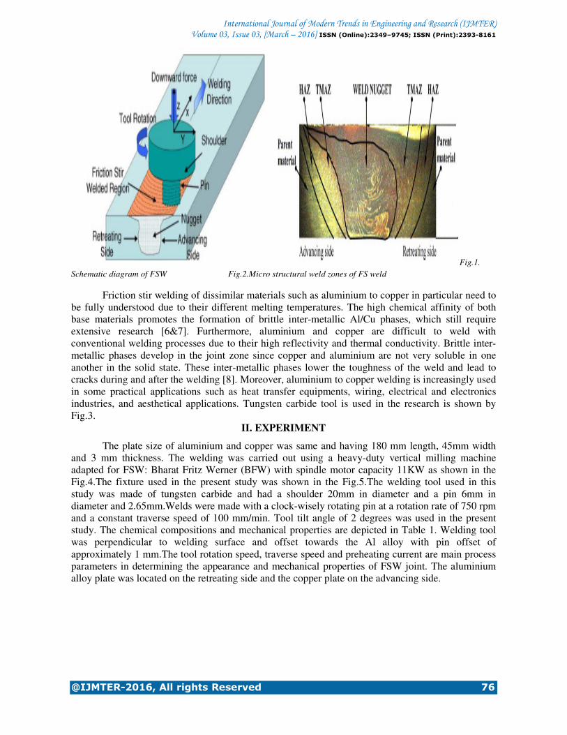
that is forced into the adjacent mating edges of the work pieces as illustrated in Fig.1.The rotation of
the tool results in the stirring and mixing of material around the rotating pin during the welding
process which in turn affect the evolving properties of the weld. There are fewer defects in solid-
state welding because the metals do not reach their melting temperatures during the welding process.
The major advantage of FSW is that it follows local thermo mechanical metal working process
without influencing properties of surrounding areas as observed in other welding process. However,
the base metals being joined retain their original properties, and the Heat Affected Zone (HAZ) is
small as compared with the fusion welding techniques [5]. The micro structural weld zones of FS
weld is shown in Fig.2.
International Journal of Modern Trends in Engineering and Research (IJMTER) Volume 03, Issue 03, [March – 2016] ISSN (Online):2349–9745; ISSN (Print):2393-8161
@IJMTER-2016, All rights Reserved 76
Fig.1.
Schematic diagram of FSW Fig.2.Micro structural weld zones of FS weld
Friction stir welding of dissimilar materials such as aluminium to copper in particular need to
be fully understood due to their different melting temperatures. The high chemical affinity of both
base materials promotes the formation of brittle inter-metallic Al/Cu phases, which still require
extensive research [6&7]. Furthermore, aluminium and copper are difficult to weld with
conventional welding processes due to their high reflectivity and thermal conductivity. Brittle inter-
metallic phases develop in the joint zone since copper and aluminium are not very soluble in one
another in the solid state. These inter-metallic phases lower the toughness of the weld and lead to
cracks during and after the welding [8]. Moreover, aluminium to copper welding is increasingly used
in some practical applications such as heat transfer equipments, wiring, electrical and electronics
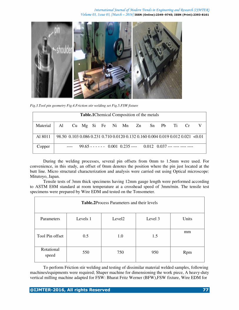
industries, and aesthetical applications. Tungsten carbide tool is used in the research is shown by
Fig.3.
II. EXPERIMENT
The plate size of aluminium and copper was same and having 180 mm length, 45mm width
and 3 mm thickness. The welding was carried out using a heavy-duty vertical milling machine
adapted for FSW: Bharat Fritz Werner (BFW) with spindle motor capacity 11KW as shown in the
Fig.4.The fixture used in the present study was shown in the Fig.5.The welding tool used in this
study was made of tungsten carbide and had a shoulder 20mm in diameter and a pin 6mm in
diameter and 2.65mm.Welds were made with a clock-wisely rotating pin at a rotation rate of 750 rpm
and a constant traverse speed of 100 mm/min. Tool tilt angle of 2 degrees was used in the present
study. The chemical compositions and mechanical properties are depicted in Table 1. Welding tool
was perpendicular to welding surface and offset towards the Al alloy with pin offset of
approximately 1 mm.The tool rotation speed, traverse speed and preheating current are main process
parameters in determining the appearance and mechanical properties of FSW joint. The aluminium
alloy plate was located on the retreating side and the copper plate on the advancing side.
International Journal of Modern Trends in Engineering and Research (IJMTER) Volume 03, Issue 03, [March – 2016] ISSN (Online):2349–9745; ISSN (Print):2393-8161
@IJMTER-2016, All rights Reserved 77
Fig.3.Tool pin geometry Fig.4.Friction stir welding set Fig.5.FSW fixture
Table.1Chemical Composition of the metals
Material Al Cu Mg Si Fe Ni Mn Zn Sn Pb Ti Cr V
Al 8011 98.50 0.103 0.086 0.231 0.710 0.0120 0.132 0.160 0.004 0.019 0.012 0.021 <0.01
Copper ---- 99.65 - - - - - - 0.001 0.235 ---- 0.012 0.037 --- ---- ---- ----
During the welding processes, several pin offsets from 0mm to 1.5mm were used. For
convenience, in this study, an offset of 0mm denotes the position where the pin just located at the
butt line. Micro structural characterization and analysis were carried out using Optical microscope:
Mitutoyo, Japan.
Tensile tests of 3mm thick specimens having 12mm gauge length were performed according
to ASTM E8M standard at room temperature at a crosshead speed of 3mm/min. The tensile test
specimens were prepared by Wire EDM and tested on the Tonsometer.
Table.2Process Parameters and their levels
Parameters Levels 1 Level2 Level 3 Units
Tool Pin offset 0.5 1.0 1.5 mm
Rotational
speed 550 750 950 Rpm
To perform Friction stir welding and testing of dissimilar material welded samples, following
machines/equipments were required; Shaper machine for dimensioning the work piece, A heavy-duty
vertical milling machine adapted for FSW: Bharat Fritz Werner (BFW),FSW fixture, Wire EDM for
International Journal of Modern Trends in Engineering Volume 03, Issue 03, [March
@IJMTER-2016, All rights Reserved
making sample for testing : Steer Corporation, China, Tensometer for Tensile testing
Instruments Pvt. Ltd. Pune.
III. RESULTS AND DISCUSSION
The effects of FSW process parameters like tool shoulder diameter,
speed, on ultimate tensile strength is studied. From the graphs, it is found that the tensile strength of
FSW joints is higher than the base metal. The four operating parameters considered directly affect
the magnitude of frictional heat genera
plate.
1) Effect of tool shoulder diameter: The tool shoulder diameter is having directly proportional relationship with the heat
generation due to friction. If the shoulder
also high due to large contact area and vice versa. In this investigation it has been observed that the
larger tool shoulder diameter (20 mm) lead to wider contact area and resulted in wider TMAZ r
and HAZ region. 2) The effect of pin offset on the tensile strength of the joints:
When the pin offset was larger towards the softer material, only a few Cu pieces with
relatively small size were moved from the Cu bulk.
shown in the fig.7. The Cu pieces were harder than the Al matrix, therefore, the large Cu pieces were
hard to deform and flow in the Al matrix, and the mixing between the large Cu pieces and the Al
matrix would be very difficult. This led to the poor surface bonding and the formation of many voids
in the weld bead. Moreover, when the pin offset was smaller, more Al
because the more Cu pieces were stirred into the nugget zone. Thus, the
Cu became poor due to the brittle nature of the IMCs.
Fig.7. Effect of pin offset on the tensile strength
0
50
100
150
200
-1.5 -1
43.6
114.6
Ult
ima
te t
en
sile
Str
en
gth
(MP
a)
AS offset values(mm) RS
International Journal of Modern Trends in Engineering and Research (IJMTER)Volume 03, Issue 03, [March – 2016] ISSN (Online):2349–9745; ISSN (Print):2393
2016, All rights Reserved
making sample for testing : Steer Corporation, China, Tensometer for Tensile testing
III. RESULTS AND DISCUSSION
The effects of FSW process parameters like tool shoulder diameter, tool pin offset,
speed, on ultimate tensile strength is studied. From the graphs, it is found that the tensile strength of
FSW joints is higher than the base metal. The four operating parameters considered directly affect
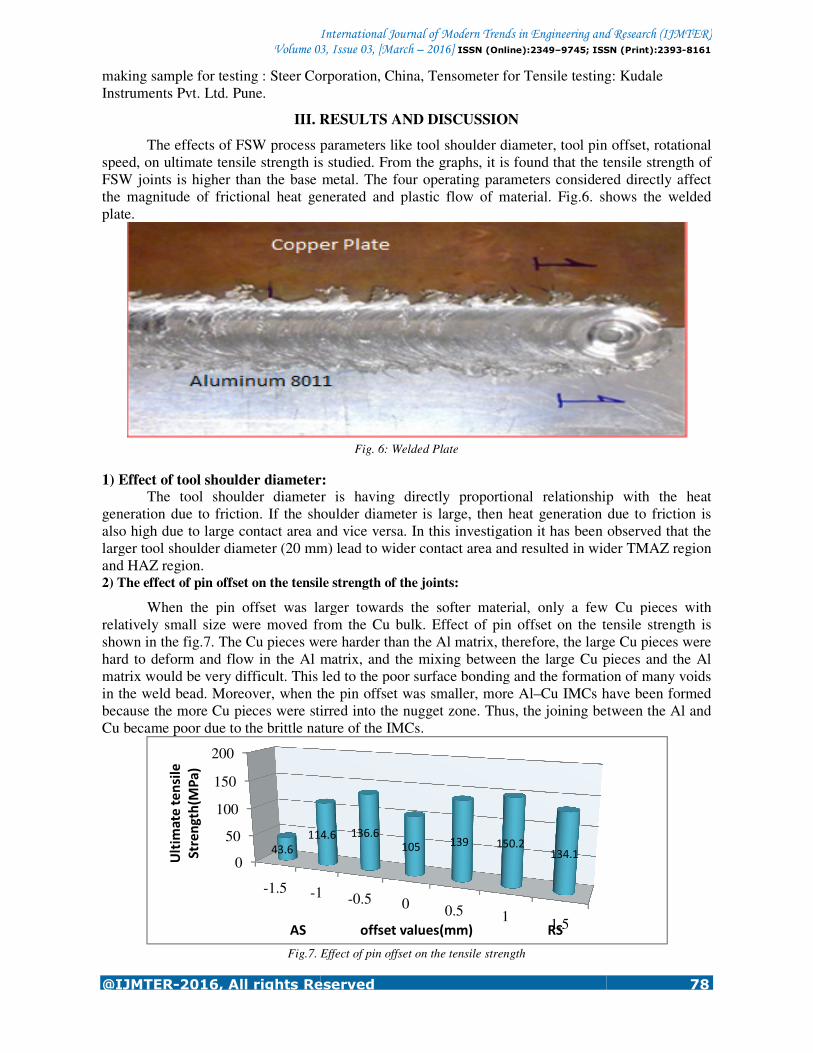
the magnitude of frictional heat generated and plastic flow of material. Fig.6. shows the welded
Fig. 6: Welded Plate
1) Effect of tool shoulder diameter: The tool shoulder diameter is having directly proportional relationship with the heat
generation due to friction. If the shoulder diameter is large, then heat generation due to friction is
also high due to large contact area and vice versa. In this investigation it has been observed that the
larger tool shoulder diameter (20 mm) lead to wider contact area and resulted in wider TMAZ r
The effect of pin offset on the tensile strength of the joints:
When the pin offset was larger towards the softer material, only a few Cu pieces with
relatively small size were moved from the Cu bulk. Effect of pin offset on the tensile strength is
The Cu pieces were harder than the Al matrix, therefore, the large Cu pieces were
hard to deform and flow in the Al matrix, and the mixing between the large Cu pieces and the Al
ld be very difficult. This led to the poor surface bonding and the formation of many voids
Moreover, when the pin offset was smaller, more Al–Cu IMCs have been formed
because the more Cu pieces were stirred into the nugget zone. Thus, the joining between the Al and
Cu became poor due to the brittle nature of the IMCs.
Effect of pin offset on the tensile strength
1 -0.5 00.5 1
1.5
114.6 136.6
105139 150.2
134.1
AS offset values(mm) RS
and Research (IJMTER) 9745; ISSN (Print):2393-8161
78
making sample for testing : Steer Corporation, China, Tensometer for Tensile testing: Kudale
tool pin offset, rotational
speed, on ultimate tensile strength is studied. From the graphs, it is found that the tensile strength of
FSW joints is higher than the base metal. The four operating parameters considered directly affect
. shows the welded
The tool shoulder diameter is having directly proportional relationship with the heat
diameter is large, then heat generation due to friction is
also high due to large contact area and vice versa. In this investigation it has been observed that the
larger tool shoulder diameter (20 mm) lead to wider contact area and resulted in wider TMAZ region
When the pin offset was larger towards the softer material, only a few Cu pieces with
Effect of pin offset on the tensile strength is
The Cu pieces were harder than the Al matrix, therefore, the large Cu pieces were
hard to deform and flow in the Al matrix, and the mixing between the large Cu pieces and the Al
ld be very difficult. This led to the poor surface bonding and the formation of many voids
Cu IMCs have been formed
joining between the Al and

International Journal of Modern Trends in Engineering and Research (IJMTER) Volume 03, Issue 03, [March – 2016] ISSN (Online):2349–9745; ISSN (Print):2393-8161
@IJMTER-2016, All rights Reserved 79
During the FSW process, the materials were transported from the retreating side to the
advancing side behind the pin where the weld was formed [16]. The hardness of the Cu is larger than
that of the Al, and the pin stirred mainly in the Al base metal during FSW, so the material flow
occurred mainly in the soft Al base metal. If the stronger material was fixed at the retreating side, the
hard material was difficult to transfer to the advancing side because the hard material hardly flew. In
this case, a large volume defect would form and the excessive soft material would be extruded out
from the nugget zone. However, when the softer material was fixed at the retreating side, the soft
material was transported to the advancing side easily, and the material flow cycle in the nugget zone
was performed normally.
3) The effect of rotational speed on the tensile strength of the joints:
Fewer cracks were seen under a lower rotation rate of 600 rpm but at 950 rpm and 1200 rpm
sound weld was not achieved. This might be due to the formation of inter-metallic compounds under
the enhanced reaction between Al and Cu. Under the rotation speed of 1200 rpm many macro cracks
were observed. When the rotation of the tool pin was high, large pieces of Cu would be detached
from the bulk and get distributed in the bottom and the retreating side of the nugget zone. When the
rotation speed was fixed to 750 rpm small pieces of Cu would be scratched off from the bulk and
thus at a certain portion of the weld zone seem to have mixed properly. The increase in rotational
speed from 750 to 1200 rpm resulted in a harsher material flow.
4) Tensile testing outcomes:
Tensile tests of 3mm thick specimens having 12mm gauge length were performed according
to ASTM E8M.Properties that are directly measured via tensile test are ultimate tensile strength,
maximum elongation and reduction in area. Fig.8 shows tensile testing specimen. Mechanical
properties of the base metal were shown in table 3.
Fig.8.TensileTesting specimen
Fig.9. fracture location at various offsets.
The fracture location position in the tensile specimens was shown in the fig.9. In the current
study, tool pin offset was varied between 0 to1.5 mm. Ultimate tensile was found to be 105MPa at
zero offset. The tensile strength of the joint was 139MPa at a pin offset of 0.5mm in Al side.
Maximum strength was obtained at a pin offset of 1mm towards Al side. The strength of the joint
was decreased at a pin offset of 1.5mm.when pin is offsetting in copper side then maximum tensile
strength was obtained at a pin offset of 0.5 mm and minimum tensile strength was obtained at a pin
offset of 1.5mm. Stress - strain curves of welded specimens welded with 750rpm and 100 mm/min
are shown in fig.10.
International Journal of Modern Trends in Engineering Volume 03, Issue 03, [March
@IJMTER-2016, All rights Reserved
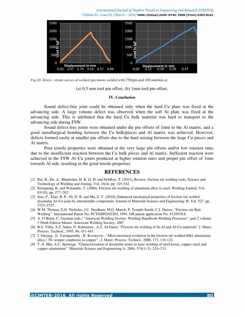
Fig.10. Stress - strain curves of welded specimens welded with 750rpm and 100 mm/min at
(a) 0.5 mm tool pin offset, (b) 1mm tool
Sound defect-free joint could be obtained only when the hard Cu plate was fixed at the
advancing side. A large volume defect was observed when the soft Al plate was fixed at the
advancing side. This is attributed that the hard
advancing side during FSW.
Sound defect-free joints were obtained under the pin offsets of 1mm to the Al matrix, and a
good metallurgical bonding between the Cu bulk/pieces and Al matrix was achieved. However,
defects formed easily at smaller pin offsets due to the hard mixing between the large Cu pieces and
Al matrix.
Poor tensile properties were obtained at the very large pin offsets and/or low rotation rates
due to the insufficient reaction between the Cu bul
achieved in the FSW Al–Cu joints produced at higher rotation rates and proper pin offset of 1mm
towards Al side, resulting in the good tensile properties
[1] Rai, R., De, A., Bhadeshia, H. K. D. H.
Technology of Welding and Joining, Vol. 16(4), pp. 325
[2] Kimapong, K. and Watanabe, T. (2004), Friction stir welding of aluminum alloy to steel, Welding Journal, Vol.
83(10), pp. 277–282.
[3] Xue, P., Xiao, B. P., Ni, D. R. and Ma, Z. Y. (2010), Enhanced mechanical properties of friction stir welded
dissimilar Al–Cu joint by intermetallic compounds. Journal of Materials Science and Engineering: B, Vol. 527, pp.
5723–5727.
[4] W.M. Thomas, E.D. Nicholas, J.C. Needham, M.G. Murch, P. Temple
Welding”. International Patent No. PCT/GB92/02203, 1991, GB patent application No. 9125978.8.
[5] A. O’Brien, C. Guzman (eds.) “American Welding Society, Welding Handbook
3 Ninth Edition Miami: American Welding Society; 2007
[6] B.S. Yilba, A.Z. Sahin, N. Kahraman , A.Z. Al
Process. Technol., 1995, 49, 431-443.
[7] J. Ouyang , E. Yarrapareddy , R. Kovacevic , “Microstractural evolution in the friction stir welded 6061 aluminium
alloy ( T6- temper condition) to copper” , J. Mater. Process. Technol., 2006, 172, 110
[8] T. A. Mai, A C. Spowage, “Characterisation of dissimilar join
copper–aluminium”. Materials Science and Engineering A, 2004, 374(1
0
500
1000
1500
2000
2500
0.03 1.97 2.74 3.54
Loa
d I
n k
gf
Displacement in mm
International Journal of Modern Trends in Engineering and Research (IJMTER)Volume 03, Issue 03, [March – 2016] ISSN (Online):2349–9745; ISSN (Print):2393
2016, All rights Reserved
strain curves of welded specimens welded with 750rpm and 100 mm/min at
0.5 mm tool pin offset, (b) 1mm tool pin offset.
IV. Conclusion
free joint could be obtained only when the hard Cu plate was fixed at the
advancing side. A large volume defect was observed when the soft Al plate was fixed at the
advancing side. This is attributed that the hard Cu bulk material was hard to transport to the
free joints were obtained under the pin offsets of 1mm to the Al matrix, and a
good metallurgical bonding between the Cu bulk/pieces and Al matrix was achieved. However,
defects formed easily at smaller pin offsets due to the hard mixing between the large Cu pieces and
Poor tensile properties were obtained at the very large pin offsets and/or low rotation rates
due to the insufficient reaction between the Cu bulk pieces and Al matrix. Sufficient reaction were
Cu joints produced at higher rotation rates and proper pin offset of 1mm
towards Al side, resulting in the good tensile properties
REFERENCES
Rai, R., De, A., Bhadeshia, H. K. D. H. and DebRoy, T. (2011), Review: friction stir welding tools, Science and
Technology of Welding and Joining, Vol. 16(4), pp. 325-342.
Kimapong, K. and Watanabe, T. (2004), Friction stir welding of aluminum alloy to steel, Welding Journal, Vol.
Xue, P., Xiao, B. P., Ni, D. R. and Ma, Z. Y. (2010), Enhanced mechanical properties of friction stir welded
Cu joint by intermetallic compounds. Journal of Materials Science and Engineering: B, Vol. 527, pp.
.D. Nicholas, J.C. Needham, M.G. Murch, P. Temple-Smith, C.J. Dawes, “Friction stir Butt
Welding”. International Patent No. PCT/GB92/02203, 1991, GB patent application No. 9125978.8.
A. O’Brien, C. Guzman (eds.) “American Welding Society, Welding Handbook Welding Processes”, part 2 volume
3 Ninth Edition Miami: American Welding Society; 2007
B.S. Yilba, A.Z. Sahin, N. Kahraman , A.Z. Al-Garni, “Friction stir welding of St-Al and Al-Cu materials” J. Mater.
. Yarrapareddy , R. Kovacevic , “Microstractural evolution in the friction stir welded 6061 aluminium
temper condition) to copper” , J. Mater. Process. Technol., 2006, 172, 110-122.
T. A. Mai, A C. Spowage, “Characterisation of dissimilar joints in laser welding of steel kovar, copper
aluminium”. Materials Science and Engineering A, 2004, 374(1−2): 224−233.
4.27 4.84
0
500
1000
1500
2000
2500
0.00 0.15 0.28 0.39 0.47
Loa
d I
n k
gf
Displacement in mm
and Research (IJMTER) 9745; ISSN (Print):2393-8161
80
free joint could be obtained only when the hard Cu plate was fixed at the
advancing side. A large volume defect was observed when the soft Al plate was fixed at the
Cu bulk material was hard to transport to the
free joints were obtained under the pin offsets of 1mm to the Al matrix, and a
good metallurgical bonding between the Cu bulk/pieces and Al matrix was achieved. However,
defects formed easily at smaller pin offsets due to the hard mixing between the large Cu pieces and
Poor tensile properties were obtained at the very large pin offsets and/or low rotation rates
k pieces and Al matrix. Sufficient reaction were
Cu joints produced at higher rotation rates and proper pin offset of 1mm
and DebRoy, T. (2011), Review: friction stir welding tools, Science and
Kimapong, K. and Watanabe, T. (2004), Friction stir welding of aluminum alloy to steel, Welding Journal, Vol.
Xue, P., Xiao, B. P., Ni, D. R. and Ma, Z. Y. (2010), Enhanced mechanical properties of friction stir welded
Cu joint by intermetallic compounds. Journal of Materials Science and Engineering: B, Vol. 527, pp.
Smith, C.J. Dawes, “Friction stir Butt
Welding”. International Patent No. PCT/GB92/02203, 1991, GB patent application No. 9125978.8.
Welding Processes”, part 2 volume
Cu materials” J. Mater.
. Yarrapareddy , R. Kovacevic , “Microstractural evolution in the friction stir welded 6061 aluminium
ts in laser welding of steel kovar, copper–steel and
0.47