Embed Size (px)
Citation preview

Interaction and Multiscale Mechanics, Vol. 5, No. 1 (2012) 1-12 1
Effect of temperature gradient on track-bridge interaction
Rakesh Kumar* and Akhil Upadhyaya
Department of Civil Engineering, IIT Roorkee, Roorkee-247667, India
(Received August 16, 2011, Revised October 24, 2011, Accepted November 27, 2011)
Abstract. Considerable longitudinal rail forces and displacements may develop in continuous weldedrail (CWR) track on long-span bridges due to temperature variations. The track stability may be disturbeddue to excessive relative displacements between the sleepers and ballast bed and the accompaniedreduction in frictional resistance. For high-speed tracks, however, solving these problems by installing railexpansion devices in the track is not an attractive solution as these devices may cause a local disturbanceof the vertical track stiffness and track geometry which will require intensive maintenance. With referenceto temperature, two actions are considered by the bridge loading standards, the uniform variation in therail and deck temperature and the temperature gradient in deck. Generally, the effect of temperaturegradient has been disregarded in the interaction analysis. This paper mainly deals with the effect oftemperature gradient on the track-bridge interaction with respect to the support reaction, rail stresses andstability. The study presented in this paper was not mentioned in the related codes so far.
Keywords: Temperature gradient; track-bridge interaction; continuous welded rail; buckling factor;numerical modeling.
1. Introduction
The demands on existing railway bridges regarding loads, speeds and robustness will continue to
increase. In order to meet the present and future demands on improved capacities for passenger and
freight traffic on the existing railway network, it is of vital importance to upgrade the existing
railway bridges and ensure that they will behave properly under increased loads and higher speeds.
Long welded/continuously welded rails (LWR/CWR) have become an inseparable component of
modern railway track structures due to their maintainability, safety and riding comfort. They are
essential for high speed operations. Residual stresses of various levels are present in the rails used
in the construction of CWR track structures. Further mechanical stresses will be added to these
residual stresses by dead weights and installation. The task of determining the longitudinal stresses
acting in a rail of continuously welded railway track is not a simple technical problem. In a welded
track the sleepers prevent displacement of rails through the track fastening elements. After the rails
are clamped, any temperature change can cause thermal stresses in the rails due to restriction of
movement.
* Corresponding author, Research Scholar, E-mail: [email protected] Professor, E-mail: [email protected]

2 Rakesh Kumar and Akhil Upadhyay
Continuing LWR/CWR track on bridges offers some advantages, but at the same time poses new
challenges as from the point of understanding of the phenomenon of track-bridge interaction. For
tracks running through a bridge, the track and bridge are interlinked to each other, regardless of
whether the track is directly fastened or laid on ballasted bed. This interlinking affects the behavior
of one on the other, which can be termed as the interaction between the bridge and the track.
The temperature at which the thermal stress in the tested cross-section of a rail is zero is defined
as the neutral or stress free temperature. It is important that the neutral temperature be in the
vicinity of the average of expected highest and lowest rail temperatures. If the discrepancy from that
average is large, rail breaks may occur at low temperatures and buckling at high temperatures.
The UIC Leaflet 774-3R and Euro-code in 1991-2:2003 include the basic methodology for
analysis of track-bridge interaction and describe the actions to be considered and the limit values to
be complied with as regards both the stresses and displacements of the rails. These standards have
been derived based upon prior researches on the related phenomena. Besides the theoretical
approach (Fryba 1985, 1997), the standards describe a method for the analysis of interaction based
upon numerical methods that idealize the behavior of all the elements and actions involved for the
computation of stresses and displacements.
According to UIC code 774-3R (2001), different longitudinal loading cases are analysed
separately considering a nonlinear stiffness law of the ballast and the various effects are
superimposed. Ruge and Birk (2006) and Ruge et al. (2009) presented a truly nonlinear formulation
of the track bridge interaction problem taking into account the combination of loading cases. A
comprehensive treatment of longitudinal effects in general is presented in the books by Fryba (1996,
chapter 14) and Esveld (2001, chapter 7).
A few new studies also came into the picture dealing with various aspects of track bridge
interaction effects. Dutoit (2009) discussed the new evolution for high speed rail line bridge design
criteria and procedures. He shows that stiff piers may take more load due to continuity of the track
passing over simply supported spans. Cutillas (2009) discussed the relevance of soil structure
interaction stiffness on the braking load and thermal actions. Davis (2009) studied the track
structure interaction under seismic conditions. He recommended avoiding large variations in
stiffness of adjacent piers.
Stability problems also arise in tracks due to the interaction. As expansion of the rails in CWR
track is restricted, a substantial temperature increase will result in high compressive stresses which
are dangerous for track buckling. Buckling may start from a small misalignment in the track and
then the track may move up to 1 m in lateral direction over a length of 10 to 20 m. The form of the
deformation is usually sinusoidal (Samavedam et al. 1993). It is extremely unsafe for trains to pass
through the deflected track configuration, since such a passage may result in a catastrophic
derailment (Van 1997, Van et al. 1995). Several hundred incidences of track buckling occur all over
the world during hot summers. From 1992 to 1997 the ERRI (the European Rail Research Institute)
Committee D 202 carried out an extensive study on the behavior of continuous welded rail (CWR)
track. This work consisted of the development of various programs, particularly for longitudinal
force distribution and buckling analysis, amongst others. In all the aforementioned works only
uniform temperature variation is considered.
All loading standards recognize the presence of temperature gradient in bridges; however, the
same is not incorporated in the track-bridge interaction analysis. Hence in the present work,
temperature gradient studies are carried out on CWR passing over bridges.

Effect of temperature gradient on track-bridge interaction 3
2. Track-bridge interaction phenomenon
Most of the tracks on high speed railways consists of continuous welded rails because of several
advantages like better riding comfort, better safety against sabotage, less mechanical wear and tear,
economical in the sense of lesser connecting elements, lesser noise etc. Reduced tractive resisting
will lead to reduced fuel consumption. Lots of work has been done in this field and along these
lines the UIC code 774-3R has been issued. This code is formulated as per the environmental and
track conditions available in Europe.
The interaction between the track and the bridge, i.e. the consequences of the behavior of one
subsystem on the behavior of other, occurs because both are connected through the wheel-rail
contact that the relative vertical movement between the two is not permitted. Providing the LWR/
CWR track over a bridge involve the transfer of forces and displacements of the bridge deck due to
thermal expansion/shortening of the rail, longitudinal forces of traction and braking forces of the
trains and locomotives from rails to bridge deck and partly to rails themselves. When the LWR/
CWR is fixed to the sleepers with the aid of elastic fasteners, and rest on a bridge deck with or
without a ballast cushion, interaction between the track and the bridge deck takes place as the two
are not free to move respect to the other. This results in setting up of additional horizontal forces in
the rails as well as in the bridge girders, which in turn will affect the design of bearings and sub-
structures as well.
3. Associated factors affecting track-bridge interaction
In case of CWR, interaction between the track and the bridge takes place, as the two are assumed
to be in perfect contact. This results in setting up of additional horizontal forces in the rails as well
as in the bridge girders, which in turn will affect the design of bearings and substructures as well.
Such forces are produced due to the following reasons:
• Temperature variation
(a) Thermal expansion of deck in the case of CWR.
(b) Thermal expansion of the deck and rails in the presence of expansion devices.
• Horizontal braking and accelerating forces.
• End rotations of the deck due to vertical traffic loads.
• Deformation of the supporting concrete structure due to creep and shrinkage.
4. Continuing CWR / LWR over bridges
If the effect of thermal variation alone is considered to be the cause of interaction between the
girder and the LWR, the girder has a tendency to expand or contract being in connection with
bearings. On the other hand, the central portion of the LWR is fixed in position irrespective of the
temperature changes that occur. This results in an inter-play of forces between the girder and the
LWR, the magnitude of the force being dependent upon the nature of fastenings being provided
between the rails and sleepers.

4 Rakesh Kumar and Akhil Upadhyay
4.1 No interaction between rail and bridge
In case of rail free fastenings, whatever, the movement of the bridge deck due to temperature
variations between the bridge and the track or the longitudinal force transferred to the rails are
dissipated either by free movement of the rails over the sleepers or by providing expansion joints in
rails at each pier. Here however, the restriction for continuing LWR for a longer length is on
account of the gap created by possible fracture of rails, which creates two breathing lengths at the
point of fracture, and the gap at the location is to be limited to 50 mm on Indian railways. So, with
rail free fastenings on the track over bridge, the span length of the LWR can only be increased by
isolating the LWR on the approaches from the bridge and by providing SEJ at each pier and at
approaches or by allowing interaction between the bridge and the track by keeping the bridge on the
central portion of LWR, i.e. away from the breathing lengths.
4.2 Interaction between rail/track and bridge deck
This raises certain issues of additional forces in the rails due to the relative movement of the
bridge deck and track due to temperature variations, additional forces in the LWR due to
longitudinal forces and bending of the decks.
5. Theory of continuous welded rail
In general, the rail is fixed to the sleepers by elastic fastenings, which apply a predetermined
clamping force to secure the rail to the sleepers. This clamping force is normally of the magnitude
such that all the longitudinal movement of the rail is transmitted to the sleepers, the resistance to
rail/sleeper sliding being greater than the resistance to longitudinal movement offered by the ballast.
As the free movement of the rail under the influence of thermal and traffic forces is opposed by the
ballast, the rails are subjected to longitudinal forces.
The thermal effects generated are shown in Figs. 1 and 2. Continuous welded rail includes a
“central zone” where expansion and contraction are completely prevented and two “breather” zones
at each end, some 150 m in length (Fig. 1). Expansion devices at the ends of the CWR have a
variation of opening of 50 mm and permit the free movement of the ends of the CWR.
Fig. 1 Force diagram for CWR under temperature variations

Effect of temperature gradient on track-bridge interaction 5
In Fig. 1, the parameters are defined as follows: α = is the coefficient of thermal expansion, δT =
is the change in rail temperature relative to the reference or laying temperature, E = is Young’s
Modulus for steel (210000 MPa), A = is the combined cross-section of two rails and P = is the force
in the track.
Fig. 2 shows a qualitative distribution of the longitudinal stresses in a long welded rail directly
fastened on a simply supported steel bridge. The distribution is plotted for the afternoon time when
the increase in temperature over datum temperature is positive for both the rail (Dt) and the bridge
(DT) and Dt is greater than DT. It can be seen from Fig. 2 that compressive stresses are developed
in the rail with magnitudes higher near the roller end of the bridge deck.
6. Variations of temperature
The UIC code considers the following aspects of temperature variations:
• Changes in the uniform component of the temperature which causes a change in length in a free
moving structure.
• Differences in temperature between the deck and the rails, in the case of track with expansion
devices.
Generally, the effects of thermal gradients will be disregarded in the interaction analysis.
Without expansion devices, the variation of temperature in the rail (δTR) does not produce relative
displacements between the rails and the deck, thus the only variation of temperature to be
considered is the change in temperature of the deck (δTD). For the interaction analysis, the stresses
in the rails due to the variation of temperature of the deck are considered as “additional stress”, to
be added to the stresses eventually due to the variation of temperature of the confined rail (σR = αR .
δTR . ER).
With expansion devices, the variation of temperature of the deck and the variation of temperature
of the rails shall be taken into account. The difference in temperature between the deck and the
track is assumed not to exceed ± 20oC.
In the case of CWR, a variation in the temperature of the track does not cause a displacement of
the track and thus there is no interaction effect due to the variation in the temperature of the track.
In fact, the temperature variation in the rails has no influence on the support reaction and the
verification of the value of rail stress is relevant only to the additional stress in the rails due to the
presence of the deck.
Fig. 2 Rail stresses due to temperature variations in the bridge deck

6 Rakesh Kumar and Akhil Upadhyay
7. Numerical modeling of track-bridge interaction
To carry out numerical studies on thermal gradient, a new numerical model has been created and
the parametric investigations are carried out using this model. The model created for the track–
bridge interaction has been shown below in Fig. 3.
The numerical models are developed to simulate the track–bridge interaction using the software
STAAD-PRO which is based on stiffness approach. The bridge and rails are modeled using the
beam elements and the connection between the two is modeled by springs (k2). The approaches of
the bridge (k1 and k3) as well as pier stiffness (Ksupport) are also incorporated in the model using
springs. The model is developed by considering the track as a continuous beam supported on a
number of discrete springs as shown in Fig. 3. The approaches in Fig. 3 shown by springs k1 and k3are modeled using the concept of Winkler foundation as shown in Fig. 4.
The CWR track over a bridge means in fact that the CWR track is resting on a surface subjected
to deformation and movements, hence causing displacement of the track. Details of various springs
shown in Fig. 3 are defined as follows:
• k1 and k3 – spring stiffness to simulate the approaches;
• k2 – spring stiffness to simulate the stiffness of the medium between the track and the bridge. It
accounts for the stiffness of sleepers and ballast, and is represented by a non-linear spring with
stiffness dependent on the loading.
• Ksupport - support stiffness of the deck. It includes the effect of following stiffness:
• Stiffness of the foundation;
• Stiffness of the piers;
• Stiffness due to displacement at the head of the support because of rotation of the foundation
slab;
Fig. 3 Model for track–bridge interaction
Fig. 4 Winkler foundation

Effect of temperature gradient on track-bridge interaction 7
• Stiffness due to displacement of the support because of the horizontal movement of the
foundation;
• Stiffness due to relative displacement between the upper and the lower parts of the bearings; and
• Stiffness due to displacement at the head of the support due to elastic deformation.
In Fig. 3 the left end of the deck is hinged and the right end is with roller support simulating the
end conditions of the deck. The upper beam used to simulate the track is continuous over the deck
and connected by springs of stiffness k2 and through springs of stiffness k1 and k3 at the two
approaches.
8. Validation of the model
Furthermore, the UIC Leaflet774-3R (Dutoit 2009) states that the numerical models used for the
track-bridge interaction shall be validated before being actually used for performing numerical
studies on them. The computing model presented in this paper and used for performing parametric
investigations on thermal gradient has been validated with the help of manual calculations carried
out using the charts provided in the UIC code of practice. During these studies the span of bridge is
varied with two different combinations of support stiffness (K) and track-bridge connecting spring
stiffness (k) i.e. K2 k20 and for K4 k20 (as defined in the UIC code) on models of deck lengths 16,
30, 60, 76 and 100 m with uniform variation of rail temperature 50oC and that of deck as 35oC,
keeping all the other parameters like soil stiffness as constant. The horizontal support reaction for
various deck-lengths has been plotted in Figs. 5 and 6.
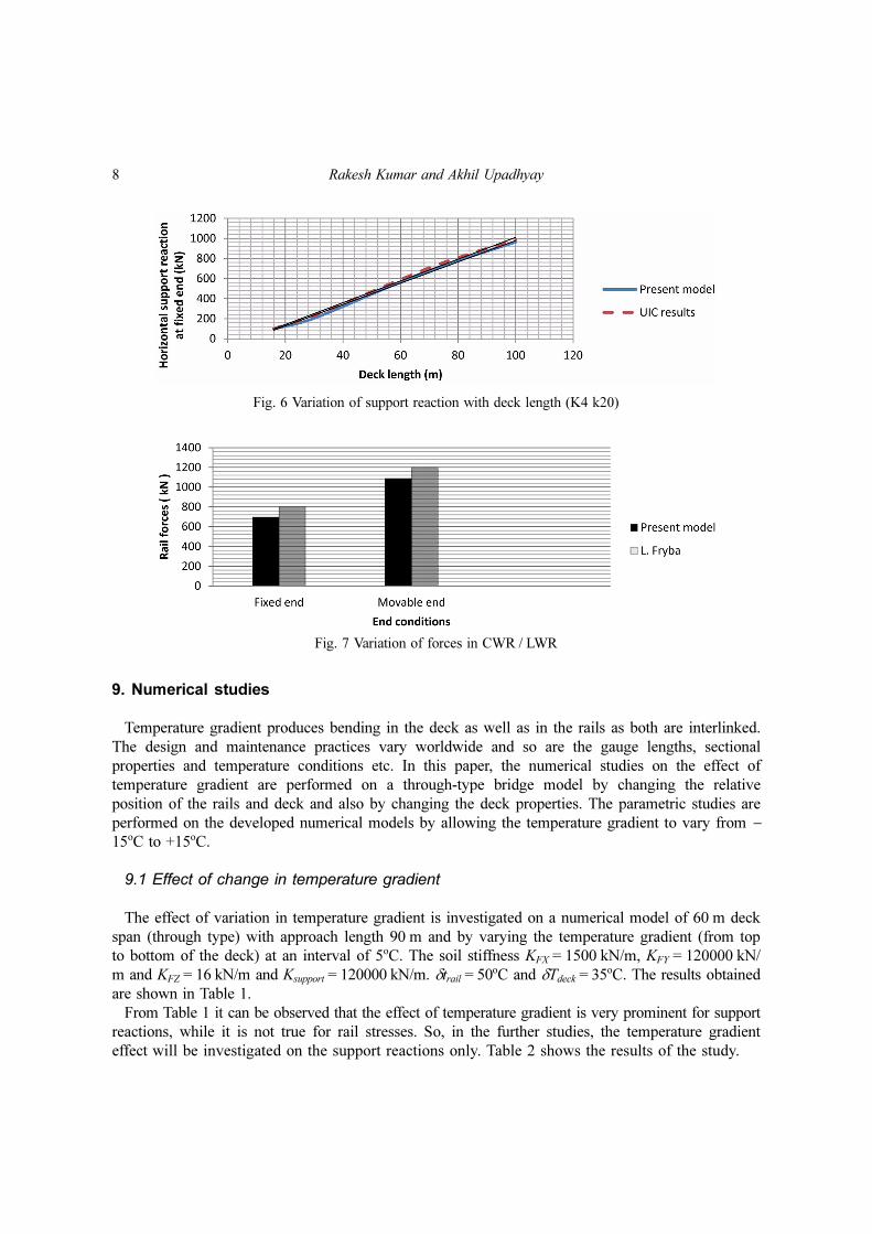
From Figs. 5 and 6, it is clear that the model values and the UIC values are generally matching.
The model values are slightly lower than the UIC values as their points are on the conservative side
as expected. A good qualitative as well as quantitative match can be obtained. The developed model
is also validated with those existing in the literature for rail forces. The variation of forces in the
LWR/CWR for the developed model having simply supported steel bridge of span 32 m and those
by L. Fryba is shown in Fig. 7. The differences between the two values are 9 to 13%. The
theoretical values obtained by L. Fryba are higher than the present numerical values, as it is
obvious. Hence the model has been validated with the UIC code of practice as well as with the
literature and was used further to perform numerical studies on the effect of temperature gradient on
the track-bridge interaction.
Fig. 5 Variation of support reaction with deck length (K2 k20)
8 Rakesh Kumar and Akhil Upadhyay
9. Numerical studies
Temperature gradient produces bending in the deck as well as in the rails as both are interlinked.
The design and maintenance practices vary worldwide and so are the gauge lengths, sectional
properties and temperature conditions etc. In this paper, the numerical studies on the effect of
temperature gradient are performed on a through-type bridge model by changing the relative
position of the rails and deck and also by changing the deck properties. The parametric studies are
performed on the developed numerical models by allowing the temperature gradient to vary from −
15oC to +15oC.
9.1 Effect of change in temperature gradient
The effect of variation in temperature gradient is investigated on a numerical model of 60 m deck
span (through type) with approach length 90 m and by varying the temperature gradient (from top
to bottom of the deck) at an interval of 5oC. The soil stiffness KFX = 1500 kN/m, KFY = 120000 kN/
m and KFZ = 16 kN/m and Ksupport = 120000 kN/m. δtrail = 50oC and δTdeck = 35oC. The results obtained
are shown in Table 1.
From Table 1 it can be observed that the effect of temperature gradient is very prominent for support
reactions, while it is not true for rail stresses. So, in the further studies, the temperature gradient
effect will be investigated on the support reactions only. Table 2 shows the results of the study.
Fig. 6 Variation of support reaction with deck length (K4 k20)
Fig. 7 Variation of forces in CWR / LWR

Effect of temperature gradient on track-bridge interaction 9
An analysis of the results obtained in Tables 1 and 2 indicates that there is a remarkable effect of
temperature gradient on support reactions, but lesser effect on rail stresses. The rate of increase in
support reaction due to the increase in temperature gradient is much higher than that of rail stresses.
Longitudinal displacement of the support occurs under this effect between the top and bottom sides
of the deck. At a particular value of temperature gradient, the rail stresses get reversed, i.e. from
compression to tension and vice-versa. Bending is more predominant in the deck-type bridges than
the through-type, which proves the significance of the present study.
9.2 Effect of relative position of rails and deck
The relative position of the centre of gravity of rails and that of the deck depends upon the
structural form of the superstructure. This fact reinforces the need of the present study. The
numerical investigations in this regard were done on the same model as described above by
changing the relative position of the rails and deck, keeping the other parameters constant. In the
absence of temperature gradient (or if there is uniform temperature variation in the rails and deck),
the relative position of the rails and the deck does not affect the values. The results of the study are
plotted in Figs. 8 and 9. This study reveals that by changing the relative position of the rails and the
deck, the support reaction is affected significantly though the buckling factor is not.
Table 1 Effect of temperature gradient (from 5oC to 15oC)
Temperature gradient (oC)
Horizontal support reaction (kN)
Percentage variation with respect to
temperature gradient of +5oC
Rail stress at fixed support (MPa)
Percentage variation with respect to
temperature gradient of +5oC
+5+10+15
-101.908-732.700
-1363.512
-5618.981237.98
56.1973.2788.13
-30.4056.84
Table 2 Effect of temperature gradient (range -5oC to -15oC)
Temperature gradient (oC) Horizontal support reaction (kN)Percentage variation with respect to
temperature gradient of -5oC
-5-10-15
1159.6961790.4902421.301
-554.39108.79
Fig. 8 Horizontal support reaction v/s temperature gradient due to relative position of rails and deck

10 Rakesh Kumar and Akhil Upadhyay
9.3 Effect of variation in deck properties
In 60 kg, 90 UTS rails when laid on 10 curve on bridges, the margin in the extent of additional
stresses in the rails has been taken as 72 MPa (compression) and 92 MPa (tension) according to the
UIC 774-3R code. These margins have to be decided for individual railways based upon a sound
understanding of the conditions existing on the railway. The UIC design charts have been prepared
for the UIC 60 rails and as per the design practices followed for the locally available deck sections.
The rail sections as well as the deck sections vary from country to country as per their availability
and so are their designs practices. It reinforces the need for this investigation. To investigate the
effect of variations in deck properties, the following two cases of deck lengths 100 m and 30 m are
considered. The observations from the results are listed in Tables 3 and 4.
For 100 m deck length
Case 1: Span = 100 m with 90 m approach, Ax = 0.74 m2, IZ = 2.59 m4, Iy = 0.60 m4, Ix = 1.10 m4
Case 2: Span = 100 m with 90 m approach, Ax = 1.0 m2, IZ = 4.5 m4, Iy = 1.1 m4, Ix = 2.25 m4
For 30 m deck length
Case 1 : Span = 30 m with approach 90 m, Ax = 0.74 m2, Iz = 2.59 m4, Ix = 1.1 m4, Iy = 0.60 m4
Case 2 : Span = 30 m with approach 90 m, Ax = 0.59 m2, Iz = 0.184 m4, Ix = 0.09 m4, Iy = 0.05 m4
Fig. 9 Buckling factor v/s temperature gradient due to relative position of rails and deck
Table 4 Percentage variation in support reaction and buckling factor (30 m deck)
Parameters Case 1 Case 2 % Variation
Support reaction (kN) 171.618 214.10 24.75
Buckling factor 0.20820 0.2074 -0.38
Table 3 Percentage variation in support reaction and buckling factor (100 m deck)
Parameters Case 1 Case 2 % Variation
Support reaction (kN) 1119.0 1134.7 1.40
Buckling factor 0.0699 0.0694 -0.71

Effect of temperature gradient on track-bridge interaction 11
From the analysis of the results, it is observed that with an increase in the deck span the
percentage increase in the support reaction decreases. The deck properties affect the support
reactions in the case of small / minor bridges. The buckling factor increases for smaller bridges as
compared to longer bridges. The percentage variation in the support reaction with and without
temperature gradient is investigated for the models with 30 m and 100 m deck. The percentage
variation obtained for the support reaction for the two cases is shown in Fig. 10. This figure shows
that with an increase in the span, the percentage increase in support reaction decreases. The support
reactions are affected considerably due to the change in deck properties for minor bridges.
10. Conclusions
With the popularity of CWR, the significance of track-bridge interaction studies has increased. In
the present study, the effect of temperature gradient on this phenomenon is studied by developing a
numerical model. From the parametric studies performed, the following conclusions can be drawn:
• The parametric study on temperature gradient shows that the influence of temperature gradient
on the support reaction is very significant and needs to be accounted for. The support reactions
are influenced considerably but the rail stresses and the buckling coefficient does not get affected
much by the gradient effect.
• The relative position of the deck and rails has a significant effect on the support reaction in the
presence of temperature gradient. However, in the absence of temperature gradient (or in the
presence of uniform temperature change), such an effect has no influence.
• With an increase in deck length, the percentage increase in support reaction decreases.
All bridge codes consider the effect of temperature gradient in the design of bridges and so the
same should be considered in the track-bridge interaction analysis.
References
Cutillas, A.M. (2009), “Track-bridge interaction problems in bridge design”, Track-bridge interaction on high-speed railways, Eds. Calcada R. et al., CRC Press, Taylor & Francis Group London, UK. Chapter 3:19-28.
Davis, S.G. (2009), “Controlling track-structure interaction in seismic conditions”, Track-bridge interaction onhigh-speed railways, Eds. Calcada R. et al., CRC Press, Taylor & Francis Group London, UK. Chapter 4:29-35.
Fig. 10 Percentage variation in support reaction

12 Rakesh Kumar and Akhil Upadhyay
Dutoit, D. (2009), “New evolution for high speed rail line bridge design criteria and corresponding designprocedures”, Track-bridge interaction on high-speed railways, Eds. Calcada R. et al., CRC Press, Taylor &Francis Group London, UK. Chapter 1:1-6
ERRI D 202, RP (1994), “Proposal for theoretical model investigations concerning CWR”.ERRI D 202, RP2 (1995), “Review of existing experimental work on behavior of CWR track”.ERRI D 202, RP4 (1997), “Stability of continuous welded rail track”.ERRI D 202, RP5 (1997), “Analysis of factors that influence the longitudinal behavior of CWR track including
lateral movement of sharp cuves”.Esveld, C. (1996), “How Safe is CWR?”, WCRR, Colorado Springs.Esveld, C. (2001), “Modern railway track”, MRT Productions, Zaltbommel.Esveld, C., Delhaz, R.C.M., Godart, P. and Mijs, J. (1995), “Avoidance of expansion joints in high-speed CWR
track on long bridges”, Rail Eng. Int., 24(3), 7-9.Fryba, L. (1985), “Thermal interaction of long welded rails with railway bridges”, Rail. Eng. Int., 16(3), 5-24.Fryba, L. (1996), “Dynamics of railway bridges”, Thomas Telford, London.Fryba, L. (1997), “Continuous welded rail on railway bridges”, World Congress on Railway Research, Firenze.Kerr, A.D. (1972), “The continuously supported rail subjected to an axial force and moving load”, Int. J. Mech.
Sci. 14, 71-78.Kish, A. and Samavedam, G. (1991), “Dynamic buckling of continuous welded rail track: Theory, tests, and
safety concepts”. Trans. Res. Board Proc., 1289, 23-38.Rajamani, R. (1987), “Long welded rails on girder bridges”, P-Way Bulletin.Ruge, P. and Birk, C. (2006), “Longitudinal forces in continuously welded rails on bridge decks due to nonlinear
track-bridge interaction”, Comput. Struct., 85, 458-475.Ruge, P., Widarda, D.R., and Birk, C. (2009), “Longitudinal track-bridge interaction for load-sequences”, Track-
bridge interaction on high-speed railways, Eds. Calcada R. et al., CRC Press, Taylor & Francis GroupLondon, UK. Chapter 10:109-127.
Samavedam, G., Kish, A., Purple, A. and Schoengart, J. (1993), “Parametric analysis and safety concepts ofCWR buckling”, US DOT-VNTSC-FRA-93-25.
UIC code 774-3R (2001) 2nd edition, “Track/bridge Interaction: Recommendations for calculations”, Paris,France.
Van, M.A. (1997), Stability of continuous welded rail track, Delft University Press, Dissertation TU Delft.Van, M.A. and Dieterman, H.A. (1995), “Sensitivity analysis of buckling of curved CWR track and a Fly-over
study”, TU Delft, Rp 3.21.1.22.33.


![Elegant The Effects of Thermal Smulaon on the Mind Club ...t1].pdf · Figure 2. Track of one worm with .5 degrees/cm temperature gradient (Karen Jiang 2014). Figure 3. Track of several](https://img.dokumen.tips/doc/110x75/5fe6b5ab3f603804325df6f3/elegant-the-eiects-of-thermal-smulaon-on-the-mind-club-t1pdf-figure-2.jpg)


![UIC 774 3 Code for Track Rail Interaction[1]](https://img.dokumen.tips/doc/110x75/5435b17b219acdd95f8b4b17/uic-774-3-code-for-track-rail-interaction1.jpg)