Embed Size (px)
Citation preview
Ž .Wear 233–235 1999 635–646www.elsevier.comrlocaterwear
Effect of HCl on the corrosion and wear of in-bed tubes in a laboratorysimulated bubbling fluidized bed
P.Y. Hou a,), Y. Niu a,b, T.J. Sum a, J. Stringer a,c
a Materials Sciences DiÕision, Lawrence Berkeley National Laboratory, Berkeley, CA 94720, USAb Institute of Corrosion and Protection of Metals, Chinese Academy of Sciences, Shenyang, China
c Electric Power Research Institute, Palo Alto, CA 94304, USA
Abstract
Ž .Heat-exchanger tubes in fluidized bed combustors FBCs often suffer material loss due to combined corrosion and erosion. The effectof chlorine on in-bed tube wastage and its possible mechanism are being studied using the EPRIrLBNL FBC wastage simulator. This testrig was designed to simulate dense particle impacts on tube bottoms with well-controlled parameters, and has been proven to closelyreflect situations found in operating bubbling FBCs. In this study, HCl gas was chosen to be the Cl source and was introduced into thefluidizing air with a 50-ppm concentration. Tests were performed at temperatures ranging from ambient to 4008C using 1018 low carbonsteel rods in a bed of commercial SiO sand that had an average size of 800 mm. The wear profile after each test was measured using a2
profilometer. Results showed an increase in material wastage rates in the presence of HCl, and that the rate was significantly higher withhigher test temperatures. Microstructural and chemical analysis of the wear surface and corrosion products are reported. It is concludedthat the dominating effect of HCl on the wastage rates is due to an enhanced oxidation and a reduced scale adherence. q 1999 ElsevierScience S.A. All rights reserved.
Keywords: Corrosion; Wear; In-bed tube
1. Introduction
Ž .A fluidized bed combustor FBC is one where coal orother fuels are burned in a fluidized bed of particles. Itsgreatest advantage over conventional combustion tech-niques is the excellent gasrsolid mixing in the bed, whichallows for a more efficient combustion at a lower tempera-ture. In a bubbling FBC, where the gas velocity in the bedis only a little greater than the minimum velocity requiredto fluidize it, heat exchange tubes are placed in the bed inbundles. One of the most serious problems associated withFBC technology is the material loss of the combustor walland the in-bed tubes. The term ‘wastage’ is commonlyused for this phenomenon, which is generally accepted tobe a result of erosion or abrasive wear that may beaccelerated by oxidation or high-temperature corrosionw x1,2 . However, not all FBCs suffer from in bed wastage,and it is far from clear how the process can occur.
One factor that may significantly affect wastage is theamount of chlorine in the coal, which can vary widely with
w xgeographical locations and depth within a mine 3 . Early
) Corresponding author
results from the 20 MWe pilot plant at TVA’s Paducah siteshowed an order of magnitude increase in wastage rate of
Ž .the evaporator tubes surface temperature about 3508Cw xwhen a higher chlorine containing coal was used 4 . Other
than the difference in Cl, the latter coal also containedmore quartz and about 1.5% more ash. Along with theswitching of the coal feed stock, there were also changesin the tube design and the bundle geometry.
Initially, the high chlorine content was believed to bew xthe cause for the enhanced wastage 5 , but further analysis
w x6 and later results from several laboratory studies seemedto suggest that the observed high wastage rate at the TVApilot plant could be caused by a combination of factors,
w xrather than a very strong chlorine effect 7,8 . However,the results from these laboratory studies were often incon-sistent. While most showed an increased corrosion ratefrom the presence of HCl, the effect on erosion or wearseemed to depend strongly on the atmosphere and thewastage mechanism.
The purpose of this work is to evaluate the effect ofchlorine on in-bed tube wastage and elucidate its mecha-nism using a laboratory apparatus that closely resemblesthe conditions within a bubbling fluidized bed. The test rig
0043-1648r99r$ - see front matter q 1999 Elsevier Science S.A. All rights reserved.Ž .PII: S0043-1648 99 00247-1

( )P.Y. Hou et al.rWear 233–235 1999 635–646636
was built based on the belief that the energetic processwithin the bed capable of generating the kind of damageobserved in practice is the impact of dense packets of bed
w xmaterial on the lower parts of the tubes 9,10 . To achievesuch conditions in a laboratory, a cylindrical specimen isheld horizontally and actuated a short distance vertically
w xwithin a minimally fluidized bed 11 . The downwardspecimen motion is controlled to produce similar frequen-
Ž . Ž .cies 0.25–2.75 Hz , velocities 0.5–2 mrs and impactŽ .forces 100–600 N as those caused by the impacting
particle aggregates in practical bubbling fluidized beds.Typically, the specimen is in motion for between 20 and
40 ms. Between these periods of high particle loading, arelatively long period of inaction follows. This simulatesthe intermittent nature of the aggregate impacts found inpractical situations. The effect of HCl on tube wastage as afunction of temperature is reported in this paper.
2. Experimental
w xDetails of the rig have been described elsewhere 12,13 ;a schematic of the apparatus with its modifications for HCltesting is shown in Fig. 1. The HCl gas was supplied from
Fig. 1. Schematics of the test apparatus.
( )P.Y. Hou et al.rWear 233–235 1999 635–646 637
a cylinder of HCl and N mixture, and introduced into the2
bed immediately before the distributor. The bed materialused was commercial silica sand with an average size of800 mm, which contained about 20% K, Ca, Al-mixedsilicates. The test specimens were 1018 carbon steel rods108 mm long and 19 mm in diameter. In order to achieve a
Ž .2.5-Jrstroke energy level maximum force of 300 N onthe specimen, the bed was partially fluidized at about 70%of the fluidizing velocity. All tests were conducted under
w xthe ‘‘low-dust’’ condition 12 where every 4 min the airvelocity was increased by 1.7 times for 20 s to thoroughlymix the bed and to reduce the fine dust particles in it. Thespecimen was heated in the bed to the desired operatingtemperature without any HCl. Test started with the intro-duction of HCl and the initiation of specimen actuation,which occurred at a frequency of 1 Hz. Test temperaturesranged from the ambient to 4008C with a HCl concentra-tion of 50 ppm. Although the apparatus is designed tooperate under heat-flux conditions, with the specimen
w xcooled in a hot bed 14 , the present series of tests wererun using isothermal conditions where the specimen andthe bed were at the same temperature. Three thermocou-ples were placed at locations above the distributor, imme-diately below the bed and next to the specimen to monitorand control the temperature. Total test duration was 40 h,at which time the HCl flow was stopped and the specimenwas cooled in the bed with a continuous air flow at thefluidizing velocity.
Wastage around the circumference of a tested specimenwas determined using a profilometer immediately aftercooling. The specimen surface was then carbon coated forobservations under the scanning electron microscopyŽ .SEM equipped with an energy dispersive X-ray analyzer
Ž .EDX . The surface morphology and composition werealso studied as a function of storage time as the specimenswere placed in a vacuum desiccator. Cross-sectional exam-inations were made by mounting the specimen in resin,sectioning using a diamond saw and then polished using anoil-based polishing material to avoid any reactions withwater-soluble chlorine-containing species.
3. Results
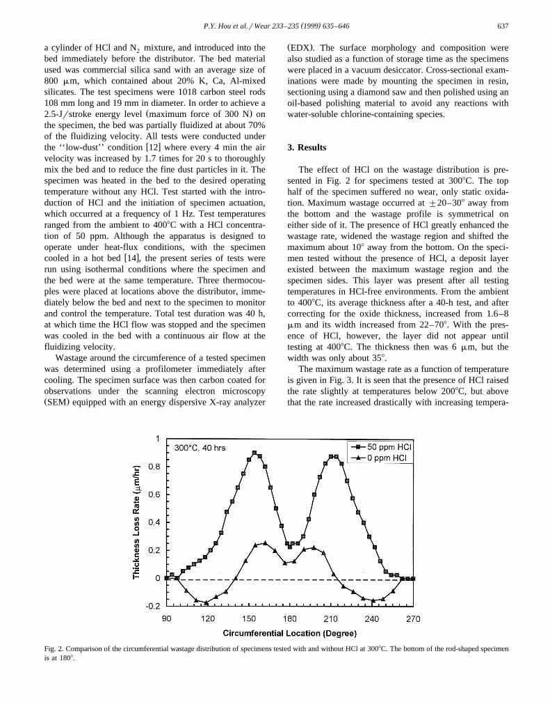
The effect of HCl on the wastage distribution is pre-sented in Fig. 2 for specimens tested at 3008C. The tophalf of the specimen suffered no wear, only static oxida-tion. Maximum wastage occurred at "20–308 away fromthe bottom and the wastage profile is symmetrical oneither side of it. The presence of HCl greatly enhanced thewastage rate, widened the wastage region and shifted themaximum about 108 away from the bottom. On the speci-men tested without the presence of HCl, a deposit layerexisted between the maximum wastage region and thespecimen sides. This layer was present after all testingtemperatures in HCl-free environments. From the ambientto 4008C, its average thickness after a 40-h test, and aftercorrecting for the oxide thickness, increased from 1.6–8mm and its width increased from 22–708. With the pres-ence of HCl, however, the layer did not appear untiltesting at 4008C. The thickness then was 6 mm, but thewidth was only about 358.
The maximum wastage rate as a function of temperatureis given in Fig. 3. It is seen that the presence of HCl raisedthe rate slightly at temperatures below 2008C, but abovethat the rate increased drastically with increasing tempera-
Fig. 2. Comparison of the circumferential wastage distribution of specimens tested with and without HCl at 3008C. The bottom of the rod-shaped specimenis at 1808.

( )P.Y. Hou et al.rWear 233–235 1999 635–646638
Fig. 3. Maximum wastage rate as a function of specimen temperature.
ture, being as much as 15 times higher at 4008C. Thew xbehavior without any HCl has been reported before 12,13 .
The present series of tests conducted under similar condi-tions confirmed earlier results in terms of the wear ratesand the temperature dependence, namely that the rate was
relatively insensitive to temperatures below 3008C, de-creased to nearly zero around 4008C and increased rapidlyat temperatures beyond 4508C. The rate decrease in theintermediate temperature regime is believed to have re-sulted from the protection of a thick and adherent depositlayer, which developed via the consolidation of very finebed particles that were impacted onto the specimen surfacew x12 .
Specimens tested with HCl addition showed signifi-cantly greater scale spallation than those tested without.The phenomenon was more severe with higher testingtemperatures and occurred only on the top half of thespecimen where there was no impact. Some spots of oxidewere spalled after the specimens were removed from thetest apparatus, but most spallation took place during stor-age at room temperature. The oxide that formed at the
Ž .higher temperatures 300 and 4008C had a dark graycolor, and the bottom half appeared smoother than the top.Exfoliation of the oxide resulted in a rust color on thespalled areas.
Fig. 4 shows the top surface of a 4008C sample testedwith HCl. Most of the scale had spalled, leaving a thinlayer of iron oxide on the metal surface. In this thin oxide
Ž . Ž . Ž . Ž .Fig. 4. a SEM micrograph, 24 h after testing, of the top surface near 08 on the specimen tested at 4008C with HCl. b A magnified portion of aŽ . Ž .showing the nodule morphologies. c EDX analysis of the thin oxide on the spalled area between the nodules. d EDX analysis of the center of the two
Ž .small nodules in b .

( )P.Y. Hou et al.rWear 233–235 1999 635–646 639
layer, a small amount of chlorine was detected. Cl-richnodules 5–40 mm in size were numerous on the spalledareas. The chemical analyses of these nodules are given inFig. 5, and it is seen that the chlorine content in themdiminished with storage time. When samples were exam-ined immediately after testing, the nodules showed only Fe
Ž .and Cl, as seen in Fig. 5 c . The majority of the noduleshad a smooth rim within which were similar Cl-richcompounds. Some smaller ones only had the rim whosecenter was a pit that appeared to be the bare metal. Crackswere often found on these nodules; an example is seen on
Ž .the largest one in Fig. 4 b .Polished cross-sections of the top region are shown in
Fig. 6. The oxide scale, which was about 5 mm thick, hadbeen totally detached from the substrate. It consisted mainlyof Fe O with only a thin layer of Fe O on the outer3 4 2 3
surface. Nodules that still contained small amounts of Clcould be found above the metal surface. The size, spacingand cracking of these nodules corresponded to those ob-
Ž .served from the surface view Fig. 4 . In some areas, as inŽ .Fig. 6 c , a thin layer of Cl-containing oxide, rather than
nodules, appeared on the substrate surface. Numerous
cracks perpendicular to the layer were apparent. The thick-ness of this layer varied across the top half of the specimenfrom less than 0.5 mm to 1 mm. The detached oxide scalewas found to be significantly thicker than if there were noHCl. Approximate oxide growth rates determined fromscale thickness and oxidation time are given in Table 1. Inthe presence of HCl, the rates increased by nearly an orderof magnitude.
Ž .In the deposit area Fig. 7 , the oxide scale was eventhicker and showed multiple layers that are characteristic
w xof scales that formed under light impact 15 . The depositlayer consisted mainly of the bed material that was mixedwith some iron oxide. Its thickness varied from 1–8 mm.At the alloy surface where the oxide had detached, Cl-con-
Ž Ž ..taining nodules were again found Fig. 7 a , but no nod-ules were found on areas where the scale remained in
Ž .contact with the substrate, as seen in Fig. 7 b .The Cl-containing nodules were found on specimens
exposed at all test temperatures. Their density and sizewere higher on the top than on the bottom half of thespecimen when the test temperature was above the ambi-
Ž . Ž .ent. Fig. 8 a and b show their appearance near 08 of the
Fig. 5. Representative EDX analysis of the nodules seen in Fig. 4. Similar compositions were found on the smooth rim and on the rough compound withinŽ . Ž . Ž .it. a is the composition 24 h after testing and b is the same area after 13 days. c Composition of a nodule formed at 2008C, 6 h after testing.

( )P.Y. Hou et al.rWear 233–235 1999 635–646640
Ž .Fig. 6. Backscattered electron images of cross-sections from the top portion of the specimen tested at 4008C with HCl. a Shows the presence ofŽ . Ž .Cl-containing nodules at the metal surface, b is the EDX analysis of one of the nodules and c shows the presence of a thin Cl-containing oxide at the
interface.
specimen tested at 2008C and at room temperature, respec-tively. The oxide scale between the nodules on the 2008Cspecimen delaminated and peeled, and the area of spalla-tion increased with longer storage time. A cross-sectionalarea near 908 of the 2008C sample is shown in Fig. 9,where the Cl-containing nodules are seen to have grown
through a thin oxide layer that had poor adherence to thesubstrate.
The morphology of the wastage area is illustrated inŽ .Fig. 10 with specimens tested at 3008C. In Fig. 10 a and
Ž .b , the surface of specimens tested with or without HCl,respectively, is compared. In both cases, the surface con-

( )P.Y. Hou et al.rWear 233–235 1999 635–646 641
Ž .Fig. 7. BES images of cross-sections from the deposit area of the specimen tested at 4008C in HCl showing a areas where the oxide scale had detachedŽ .from the substrate prior to polishing and b areas where the scale was in contact.
sisted of a deformed mixture of bed material debris andoxides. Small amounts of chlorine were detected in thismixture on the specimen tested in HCl, and Cl-containingnodules, like the one shown on the lower right corner of
Ž .Fig. 10 a , were often present. The principle features werethe frequent wear scars shown in the micrographs. Cross-sections from the wastage regions are shown in Fig. 11.Again, in both cases, the morphology appeared similar.The metal below the surface was sometimes deformed intofoils that were aligned in the direction of particle flow overthe surface. Without HCl, the damage in the metal wasmore severe. Between the metal foils was a thin layer ofiron oxide mixed with some bed materials. With HCl, thislayer was thicker and contained more iron oxide. At 4008Cwith HCl, the cutting into the metal became even lesssevere, as seen in Fig. 12.
4. Discussion
The mechanism of material removal resulting from theimpact conditions in our test rig is believed to be that of
w xlow cycle fatigue resulting from three-body abrasion 16 .Since the bed is dense, the particles are essentially incontact with the rod surface continuously as they movearound the circumference during the high velocity impact.The wastage depends on the normal load at a givenlocation and the distance that the contacting particle travelsunder that load. With the increase in operating tempera-ture, two competing processes become important. One isthe growth of the oxide scale and the other the formationof a dense deposit layer that is a mixture of the bed
w xmaterial with some of the surface oxide 12,13 . If thedeposit layer can build up in thickness with repeatedimpacts faster than processes that are involved in materialremoval, it will protect the underlying metal from wastage.A transition from wastage to protection usually occurs
w xaround 4008C 13 . Similar deposit layers are commonlyw xfound in practical units 17 , where they can at times
w xbecome very protective to in-bed tubes 18 . The depositlayer is believed to have formed upon impact by thetransferring of fine agglomerates that consisted of consoli-dated sub-micron particles, which resulted from particle
w xattrition 12 . Favorable conditions for its formation de-

( )P.Y. Hou et al.rWear 233–235 1999 635–646642
Ž . Ž .Fig. 8. SEM images of Cl-rich nodules formed on the top of the specimen tested at a 2008C and b 258C.
pend on the amount of fine dust particles retained in thebed, the composition of the bed, the type of oxide thatforms on the specimen surface and the temperature differ-
w xence between the bed and the specimen surface 13 . Athigher temperatures, the wastage rate becomes dominatedby oxidation as the scale thickens faster than the depositcan develop. Scales that form to a critical thickness wouldspall as a result of repeated impacts then regrow. The
process is similar to the wear enhanced oxidation regimew xdescribed by Rishel et al. 19 .
The presence of HCl in the bed, despite increasing thewastage rates, did not seem to change the wear mecha-
Ž .nism. The wear scars shown in surface view Fig. 10 andŽ .in cross-section Fig. 11 were similar to those found on
specimens tested without any HCl. Material loss still in-volved cutting by the impacting particle as it travelled on

( )P.Y. Hou et al.rWear 233–235 1999 635–646 643
Fig. 9. BES image of a cross-sectional area from the deposit region of the specimen tested at 2008C with HCl.
the specimen surface. Consequently, the wear distributionalong the circumference of the rod was not substantially
Ž .altered Fig. 2 . Maximum wastage occurred at "20–308
away from the bottom with considerably less wastage atthe bottom. The wider and slightly shifted wastage regionon the HCl-affected sample are merely a consequence ofthe higher wastage rate and the lack of a protective depositlayer. It is not entirely clear why less deposits formedwhen testing involved HCl; only partial layers were ob-served at 4008C, as seen in Fig. 7. In light of the discus-sion given in the previous paragraph, the most probablereason is that the higher oxidation rate and the less adher-ent nature of the oxide scales competed with the develop-ment of this deposit layer.
The increase in wastage rates in HCl containing atmo-spheres became more severe with increasing temperaturesŽ .Fig. 3 . At 200, 300 and 4008C, the rate increased by afactor of 2.5, 8 and 15, respectively. The enhanced rate isbelieved to be caused by an enhanced oxidation and areduced scale adherence. The higher oxide growth rate isclearly shown in Table 1, and the poor scale adhesion canbe seen from micrographs presented in Figs. 4 and 6–9.Due to these effects, one can envisage the wastage processbeing where the oxide is constantly being removed thenreformed under the impacting condition. Both the ease ofremoval and the rate of reform increased due to the
Table 1Parabolic rate constants determined from scale thicknessa
2Ž . Ž .Temperature 8C k cm rsp
bWithout HCl With 50 ppm HCly1 3300 2.1=10
y1 3 y12400 2.6=10 1.7=10y1 3450 6.3=10y1 2500 1.4=10y1 2550 3.1=10
a Measured from specimen cross-section after testing.b w xFrom Ref. 15 .
presence of HCl; consequently, the wear rate increased. AtŽ .4008C Fig. 12 , the cutting into the substrate that was
Ž .observed at lower temperatures Fig. 11 was significantlyless, indicating the more important role of oxidation.
It is not surprising that HCl enhanced oxidation rate andreduced scale adherence. The fact that its presence can
w xincrease oxidation rates is well known 20–22 , and Cl atthe scaleralloy interface is generally believed to weaken
w xit. One study 23 has shown that the presence of Cl in thescale and at the scaleralloy interface could cause thebreakaway oxidation of a Ni–Cr alloy; the Cl at thescaleralloy interface was responsible for the extremelypoor scale adherence. It has also been suggested that if alayer of FeCl should form at the scaleralloy interface,2
complete scale disruption andror spalling would be ex-pected; this would be due to an increased growth stressgenerated by the six-fold volume expansion relative to theconsumed metal as compared to the two-fold increase for
w xmagnetite 24 .From the Fe–O–Cl phase stability diagram shown in
Fig. 13, it is apparent that under our test conditions, FeCl2
should not form unless it either developed at the onset ofoxidation as it competed with oxide formation, or Clpenetrated through the oxide layer to the scaleralloy inter-face. Since heating of the specimen was always donewithout the introduction of HCl and the process usuallytook 2–3 h, the first of the above assumptions is not likely.The mode and mechanism by which chlorine permeates a
w x‘‘protective’’ scale remains speculative 25 . HCl probablygained access to the scalermetal interface by passing
w xalong naturally occurring micro-cracks and pores 26 pre-sent in the oxide scales. In the impacting condition of ourtest rig, such micro-cracks must be numerous on thebottom half of the specimen. Once at the metal surface, theHCl can react with the substrate to form FeCl .2
A thin layer of chloride seems to have developed at thescaleralloy interface at 4008C, but the most often observedCl-containing compounds were nodules associated withpitting and were found at all temperatures on all locations.

( )P.Y. Hou et al.rWear 233–235 1999 635–646644
Ž . Ž .Fig. 10. SEM images of representative impact scars found in the region of maximum wastage on specimens tested at 3008C a with HCl and b withoutHCl.
At least for the 4008C condition, the nodules were clearlyseen to have developed during cooling as the iron oxidescale delaminated and HCl penetrated to the scaleralloyinterface. The growth rate of these nodules must be veryhigh judging from their thickness as compared to that ofthe iron oxide scale. This fast growth probably gave theircharacteristic morphology of a protruding lump. Theamount of Cl in these compounds decreased with storage
time as FeCl reacted with moisture to form Fe O .2 2 3
Associated with this reaction is a volume decrease by afactor of 2.6. This is why tensile cracks on these originally
Ž Ž .FeCl compounds were often observed as in Fig. 4 b and2.Fig. 6 . At temperatures below 4008C, it is not yet clear
whether the nodules developed during cooling or testing.The oxide scales may be thin enough for HCl to penetratethrough and form these nodules. Testing with small

( )P.Y. Hou et al.rWear 233–235 1999 635–646 645
Ž . Ž .Fig. 11. BES images of cross-sections from the region of maximum wastage on specimens tested at 3008C a with HCl and b without HCl.
coupons that can be quickly removed from the bed andmounted for cross-sectional observations will be per-formed to further investigate this phenomenon.
5. Conclusions
The presence of HCl in a fluidized bed has been shownto increase in-bed tube wastage rates under a simulated
bubbling FBC environment, where the bottom portion ofthe tube was worn by dense particle impacts. The rateswere 2–3 times higher below 2008C, but increased to 8–15times higher at 300 and 4008C, respectively. The wastagemechanism was not changed by the presence of HCl.Higher rates resulted from an accelerated oxidation and areduced scale adhesion. Chlorine penetrated through theoxide scale to the scaleralloy interface to form either a
Fig. 12. BES images of cross-sections from the region of maximum wastage on the specimen tested at 4008C with HCl.

( )P.Y. Hou et al.rWear 233–235 1999 635–646646
Fig. 13. Phase stability diagram for the Fe–O–Cl system at 3008C.
thin layer or a nodular type iron chloride. The thin layerwas only found after testing at 4008C, but the nodular formexisted on specimens tested at all temperatures. It is notyet clear whether these nodules developed during testingor cooling.
Acknowledgements
This work was supported by the Electric Power Re-search Institute under project WO8032-10 through anagreement with the US Department of Energy, contract no.DE-AC03-76SF00098. The work carried out in Shenyangwas partially supported by the National Natural ScienceFoundation of China under project N. 59725101.
References
w x1 J. Stringer, Current information on metal wastage in fluidized bedŽ .combustors, in: J.P. Mustonen Ed. , Proc. 9th Int. Conf. on Flu-
idized Bed Combustion, Boston, MA, May 1987, ASME, NewYork, NY, 1987, pp. 685–696.
w x2 J. Stringer, J.W. Stallings, J.M. Wheeldon, Wastage in bubblingŽ .fluidized-bed combustors: an update, in: A.M. Manaker Ed. , Proc.
10th Int. Conf. on Fluidized Bed Combustion, San Francisco, CA,April 30–May 3, 1989, ASME, New York, NY, 1989, pp. 857–862.
w x3 L.J. Bragg, R.B. Finkelman, S.J. Tewalt, Distribution of chlorine inŽ .United States Coal, in: J. Stringer, D.D. Banerjee Eds. , Chlorine in
Coal, Elsevier, NY, 1991, pp. 3–10.w x4 R.Q. Vincent, J.M. Poston, B.F. Smith, Erosion experience of the
Ž .TVA 20 MW AFBC Voiler, in: J.P. Mustonen Ed. , Proc. Int’l.Conf. on Fluidized Bed Combustion, ASME, 1987, pp. 672–684.
w x5 J.M. Stencel, R.E. Gonzalez, J.L. Schaefer, J.K. Neathery, J.M.Wheeldon, R.Q. Vincent, D.A. Canonico, Effect of chlorine onwastage of in-bed heat exchanger surfaces under FBC conditions, in:
Ž .A.V. Levy Ed. , Proc. Corrosion–Erosion–Wear of Materials atelevated temperatures, LBL, Berkeley, CA, Jan. 31–Feb. 2, 1990,pp. 32.1–32.11.
w x6 J.M. Wheeldon, An alternative conclusion to effect of chlorine onwastage of in-bed heat exchanger surfaces under FBC conditions by
Ž .J.M. Stencel et al., in: A.V. Levy Ed. , Proc. Corrosion–Erosion–Wear of Materials at Elevated Temperatures, LBL, Berkeley, CA,Jan. 31–Feb. 2, 1990, pp. 33.1–33.3.
w x7 V.K. Sethi, I.G. Wright, Evaporator tube wastage and chlorine, in: J.Ž .Stringer, D.D. Banerjee Eds. , Chlorine in Coal, Elsevier, NY,
1991, pp. 417–423.w x8 R.Q. Vincent, A.M. Manaker, Effect of chlorine content on materials
exposed in coal fired fluidized beds, in: J. Stringer, D.D. BanerjeeŽ .Eds. , Chlorine in Coal, Elsevier, NY, 1991, pp. 389–409.
w x9 P.A. Olowson, A.E. Almstedt, Influence of pressure and fluidizationvelocity on the bubble behavior and gas flow distribution in a
Ž .fluidized bed, Chem. Eng. Sci. 45 1990 1733–1741.w x10 T.C. Kennedy, A Study of Forces on Immersed Tubes in Fluidized
Bed, EPRI CS-1542, Project 718-2, Topical Report, 1980.w x11 S.S. MacAdam, J. Stringer, Development of a unique laboratory
Ž .scale fluidized bed wear testing unit, Wear 135 1990 403–422.w x12 S.S. MacAdam, J. Stringer, Temperature dependence of steel wastage
Ž .in a bubbling fluidized bed simulator, Corrosion 49 1993 156–169.w x13 P.Y. Hou, S.S. MacAdam, H. Zhang, J. Stringer, Summary of results
from the Berkeley in-bed tube erosion simulator, Mater. High Temp.Ž .14 1997 325–335.
w x14 H. Zhang, P.Y. Hou, J. Stringer, The effect of temperature gradienton steel tube wastage in a bubbling fluidized bed simulator, Wear
Ž .197 1996 286–294.w x15 S.S. MacAdam, Mechanisms of Oxidationr3-Body Abrasion in
Steels, MS Thesis in Materials Science and Mineral Engineering,University of California at Berkeley, 1993.
w x16 S.S. MacAdam, J. Stringer, Particle impact and impact distributionŽ .within a fluidized bed combustor environment, Wear 141 1991
373–394.w x17 J.E. Oakey, A.J. Minchener, J. Stringer, Ash deposition in atmo-
spheric pressure fluidised bed combustion systems, J. Inst. EnergyŽ .62 1989 208–219.
w x18 J.M. Wheeldon, J.W. Stallings, V.K. Sethi, I.G. Wright, Preliminaryresults from a programme to identify bed material properties whichmay have promoted metal loss from evaporator tubing in TVA’s
Ž .20-MWe bubbling AFBC pilot plant, in: A.V. Levy Ed. , Proc. ofConference on Erosion–Corrosion–Wear of Materials at ElevatedTemperatures, Houston, TX, NACE, 1991, paper no. 22.
w x19 D.M. Rishel, F.S. Pettit, N. Birks, Some principal mechanisms in thesimultaneous erosion and corrosion attack of metals at high tempera-
Ž .ture, in: A.V. Levy Ed. , Proc. of Conference on Erosion–Corro-sion–Wear of Materials at Elevated Temperatures, NACE, Houston,TX, 1991, paper no. 16.
w x20 D. Bruce, P. Hancock, Influence of mechanical properties of surfaceoxide films on oxidation mechanisms: Pt. 1. A vibrational techniqueto study the nature and growth of thermally formed oxide films on
Ž .metals, J. Inst. Met. 97 1969 140–148.w x21 M.H. Rhee, M.J. McNallan, M.F. Rothman, Long term high temper-
ature corrosion studies of high temperature alloys in chlorine con-Ž .taminated environments, J. Mater. Energy Syst. 7 1986 294–301.
w x22 E. Reese, H.J. Grabke, Effects of chlorides on the oxidation of theŽ .2.25 Cr–1 Mo steel, Werkst. Korros. 43 1992 547–557.
w x23 P.Y. Hou, J. Stringer, A study of the apparent detrimental effect of asurface applied HfO coating on the oxidation behavior of alloys, J.2
Ž .Electrochem. Soc. 138 1990 327–328.w x24 P.J. James, L.W. Pinder, Effect of coal chlorine on the fireside
corrosion of boiler furnace wall and superheaterrreheater tubing,Ž .Mater. High Temp. 14 1997 187–196.
w x25 H.J. Grabke, E. Reese, M. Spiegel, The effects of chlorides, hydro-gen chloride, and sulfur dioxide in the oxidation of steels below
Ž .deposits, Corros. Sci. 37 1995 1023–1043.w x26 M. Schutze, Plasticity of protective oxide scales, Mater. Sci. Tech-
Ž .nol. 6 1990 32–38.