Embed Size (px)
Citation preview

Page 1 of 6
Effects of Changing Design Parameters on Girders
12/9/2016
This issue affects users who change design parameters and reanalyze previously saved girders. Design
parameters include, the building code, live load type (Snow or Construction), bottom chord live loads,
limited access loads, and wind design method (for example, Components/Cladding (C-C) to Main Wind
Force Resisting System (MWFRS)).
When the girder loads are originally applied to the truss, the program calculates appropriate loads for
the secondary load cases based on the original design parameters. These loads are saved with the
original truss in the appropriate load cases. When a user changes a design parameter, load cases may be
added or removed. For example, changing from snow loading to construction will remove the snow load
cases and add construction load cases. These new construction load cases will not contain the girder
loads because the construction load cases did not exist when the girder loads were originally applied.
That is why, after changing design parameter(s) on a girder truss, users should either “Reset All Load
Cases” under Special Loads and then reapply the girder loads to properly load the truss, or examine all
the loads cases to ensure the loads have been applied as expected.
Let’s run an example showing loads removed from a girder by changing design parameters, and the
correct process to reapply these loads.
The original truss is loaded at 30/10/0/10 and spaced at 24” o.c. The girder load, which is produced by a
10’ span was applied through Special Loads – Girder Loading – Create – Standard (Figure 1). The wind
design method used on this truss is Main Wind Force Resisting System (MWFRS) (Figure 2).
Figure 1 - Original Truss carrying a 10’ span
Page 2 of 6
Effects of Changing Design Parameters on Girders
12/9/2016
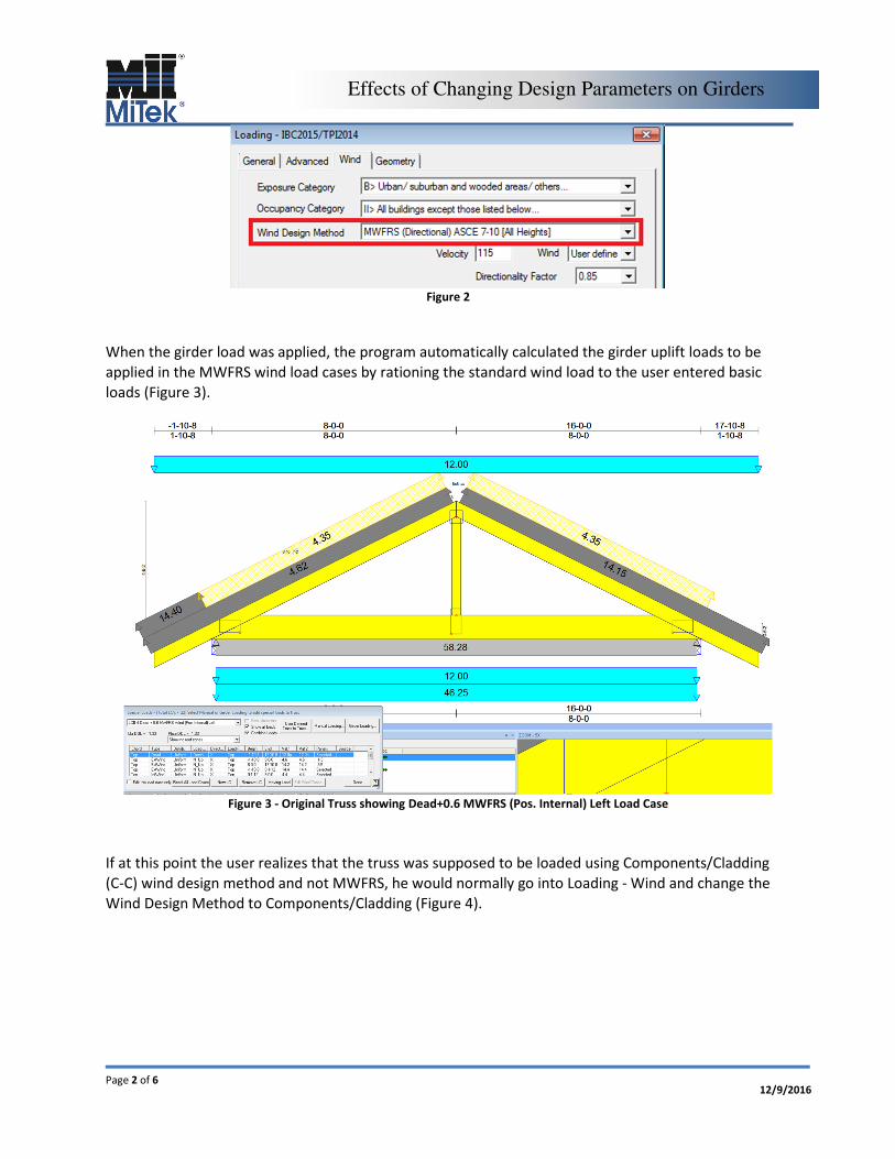
Figure 2
When the girder load was applied, the program automatically calculated the girder uplift loads to be
applied in the MWFRS wind load cases by rationing the standard wind load to the user entered basic
loads (Figure 3).
Figure 3 - Original Truss showing Dead+0.6 MWFRS (Pos. Internal) Left Load Case
If at this point the user realizes that the truss was supposed to be loaded using Components/Cladding
(C-C) wind design method and not MWFRS, he would normally go into Loading - Wind and change the
Wind Design Method to Components/Cladding (Figure 4).

Page 3 of 6
Effects of Changing Design Parameters on Girders
12/9/2016
Figure 4
Upon exiting the wind load menu, the user is presented with the following dialog box asking what to do
with the loads (Figure 5).
Figure 5
If the user selects “Cancel”, the program does not go through and recalculate the loads for any new load
cases that are added by changing the design parameter. In this example, C-C wind creates new load
cases. Consequently, the user will see a new C-C load case(s) added without any girder load applied
(Figure 6).

Page 4 of 6
Effects of Changing Design Parameters on Girders
12/9/2016
Figure 6 - Dead+0.6 C-C Wind (Pos. Internal) Case 1 Load Case without any girder loads
This design is now inaccurately loaded. At this point, the user must go to Special Loads, Reset All Load
Cases (Figure 7) and reapply the 10’ span load to the truss through Special Loads – Girder Loading –
Create - Standard.
Figure 7
By choosing “OK”, the user is telling the program to go through and recalculate the entered girder load
for all load cases. The program will automatically calculate the proper girder loads for the C-C wind load
cases and all other secondary load cases.

Page 5 of 6
Effects of Changing Design Parameters on Girders
12/9/2016
Figure 8 - Dead+0.6 C-C Wind (Pos. Internal) Case 1 Load Case with proper girder loading
Similar behavior can be seen if a user changers other design parameters after applying girder loads.
If auto loading from Structure was used, the user must reanalyze all of the carried trusses along with
girder truss(es). Then reopen each girder, go to Edit (Truss Basics) – Loading and click OK (Figure 9).
Figure 9
Page 6 of 6
Effects of Changing Design Parameters on Girders
12/9/2016
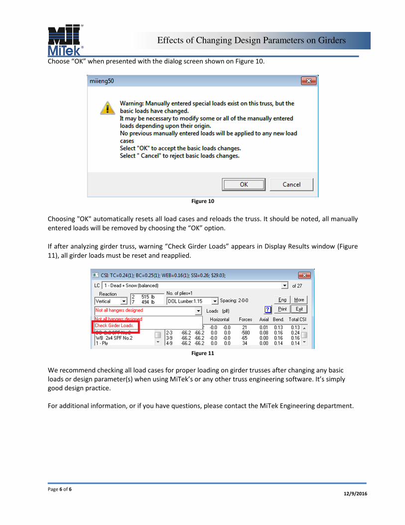
Choose “OK” when presented with the dialog screen shown on Figure 10.
Figure 10
Choosing "OK" automatically resets all load cases and reloads the truss. It should be noted, all manually
entered loads will be removed by choosing the “OK” option.
If after analyzing girder truss, warning “Check Girder Loads” appears in Display Results window (Figure
11), all girder loads must be reset and reapplied.
Figure 11
We recommend checking all load cases for proper loading on girder trusses after changing any basic
loads or design parameter(s) when using MiTek’s or any other truss engineering software. It’s simply
good design practice.
For additional information, or if you have questions, please contact the MiTek Engineering department.