Embed Size (px)
Citation preview

EF1-230V Hand-Held WelderOperating Manual
For use Only with UPP™ Electrofusion Components
Franklin Fueling Systems • 3760 Marsh Rd. • Madison, WI 53718 USA
Tel: +1 608 838 8786 • 800 225 9787 • Fax: +1 608 838 6433 • www.franklinfueling.com

2
Warning UPP™ welding units must never be operated in Zone1 or Zone 0 areas!
Hazardous area definitions are from European Directive 1999/92/EC (further guidelines can be found in the APEA Blue Book 2nd Edition).Further guidelines are found in IEC 60079-10-1, “Explosive atmospheres - Part 10-1: Classification of areas - Explosive gas atmospheres”Safety• The EF1 is designed for usage on construction sites and meets applicable
European and International safety standards. The machine should be handled with the care usually given to electrical equipment, especially during transport.
• The machine must only be used outside of hazardous areas (zones 0, 1 and 2).• Each time it is used, check the condition of the machine, particularly the
mains power cable. If any damage is discovered, contact the supplier immediately and do not use the machine.
• Check the state of the welding cables before use and replace them if there is any doubt about their condition.
• Protect the welder from getting wet. • Always check that the power source is within the parameters shown below
before using the EF1.• Never lift or pull the machine by its power cable or the welding cables. Never
disconnect welding cables by pulling the cable; always pull off the connectors.• Never re-weld a fitting that is still warm. Serious fire or burn damage
can occur and hot material may be ejected from the weld zone. Power conducting elements may become exposed creating an electrical shock hazard.
Liability RestrictionsAll liabilities of the supplier are invalidated in the following cases:• The EF1 is used outside the indicated application area.• Non-UPP™ fittings or pipe are used.• The operator has not been trained to use the EF1 or the UPP™ system.• Operating instructions have not been observed.• Unauthorised repairs, maintenance or modifications have been carried out.• The EF1 has been used outside of its technical specification.• Safety instructions have not been observed.• Improper or inadequate maintenance.• Misuse, physical abuse or any use not in accordance with the operating
manual or good industry practice.• Improper site preparation or site maintenance.

3
Technical SpecificationsStock code _________________ EF1-230V
Supply voltage ______________ 230 V +/- 15% (194 V to 264 V)
Supply frequency ____________ 50/60 Hz (40 Hz to 70 Hz)
Supply power _______________ 2.8 kW / 3.5 kVA
Supply protection ____________ Class 1 earthed (grounded)
Environmental protection ______ IP65
Operating temperature ________ -15 ºC (5 ºF) to +45 ºC (113 ºF)
Shipping dimensions 460 mm (18") wide x 210 mm (8.3") deep x 210 mm (8.3”) high
Shipping weight _____________ 3.6 kg (8 lb)
Power SupplyWelder must be powered with:• A quality 230 VAC, 50 Hz power supply with maximum tolerance of ± 15%.• A quality generator capable of supplying a minimum of 2.8 kW (3.5 kVA).
Note that an earth-spike (grounding rod) must be used with generators.If used with a 110v to 230v step-up transformer follow these specifications:
• Safety Isolating transformer: 3.3 kVA minimum.• Auto transformer: 3.3 kVa minimum.
Extension Cords / CablesExtension cables must comply with or be equivalent to H07RN-F specifications. Cable use must comply with the following table.
Wire Size Metric
AWG Wire Size
Maximum Length, meters
Maximum Length, feet
1.5 mm 15 25 822.5 mm 13 50 1644.0 mm 11 75 246
Note: All cable must be unwound from reel to prevent inductive heating effects.

4
Note: EF1 welding cables use special 7 pin connectors.
PartsBridging cables (x2)
EF1 Electrofusion Welder
7pin Secondary welding cable
Power cable
7 Pin Fusion chamber welding cable
ApplicationThe EF1 is designed to automatically weld UPP™ Primary and Secondary Containment electrofusion fittings, Electrofusion Chambers and Large diameter 10 amp fittings. This is done by using color-coded welding leads as shown below.
Type of
Fitting
Welding Cable Colour
Size of Welding
Pin (mm)
Current (amps)
Weld Time @ 20C
(Seconds)
Primary and Gemini Secondary fittings Red 4 4 184
Secondary Green 2 5 80
Fusion Chamber White 2.3 7 360
Large Diameter (10amp) Black 2 10 365
The EF1 can be used in ambient temperatures between -15 °C (5 ºF) and +45 °C (113 ºF). Only personnel fully trained and certified in the use and installation of the UPP™ system should use this equipment.
7 pin Primary and Gemini Secondary welding cable

5
Main FeaturesUPP™ electrofusion fittings are welded using a constant current. The EF1 automatically recognizes the fitting when connected and applies the correct amount of energy for a successful weld.
7 pin Weld cable connector
Fault indicator
Weld progress LED’s
Temperature sensor
Power on Indicator
ON / OFF Switch (on side of unit)
START / STOP button
The EF1 takes the ambient temperature into account when calculating the energy required to weld correctly. It must therefore be allowed to reach ambient temperature before use and must be at the same temperature as the fitting to be welded. The temperature sensor is located adjacent to the power cable entry gland.
The EF1 works on standard alternating current and either a mains connection or a generator can be used. Generators must have a rated output of at least 3.5 kVA and power input must be between 194 and 264 volts at 40 to 70 Hz.
The EF1 has an on / off button, a weld start button and an LED display showing the weld progress. The LEDs can also show any fault conditions that may affect the weld.

6
Using the EF1• Ensure that the machine is positioned outside hazardous zones
ATEX 0, 1 and 2.• Allow the machine and fittings to reach the ambient temperature of the site.• Keep the machine out of direct sunlight and free of any obstruction.• Make sure fittings and pipe have been prepared in accordance with UPP™
Installation instructions.Follow the steps below to weld Electrofusion fittings.
1. Connect the required welding lead to the EF1 Welder: PRIMARY and GEMINI SECONDARY fittings = RED (ORANGE) cable SECONDARY fittings = GREEN cable FUSION CHAMBER = WHITE cable 10 AMP fittings = BLACK cable
2. Connect the welding lead to the UPP™ fusion fitting(s), making sure connectors are firmly pushed onto the pins.
3. Connect the EF1 Welder to suitable 230V power supply.4. Turn the unit ON. All LEDs light in sequence, then green Power LED
remains on.5. Momentarily depress the orange START button until first weld light
illuminates. The first weld light comes on, then successive LEDs light up until green 100% LED is lit, showing weld is complete.
6. Disconnect welding lead from fitting. The 100% LED and Power LED remains on.
7. ALWAYS Reset for next weld by holding START button for 3 seconds. All LEDs will light in sequence, then the green power LED remains on.
Other Important Tips• Switch off the machine during breaks and at the end of the job.• The weld cycle can be stopped at any time by pressing the START/STOP
button. This will generate an error code and you must wait for the fitting to cool before attempting to continue.
• If you have any doubt about a welded joint, UPP™ fittings can be welded again provided they are left to cool at ambient temperature for a minimum of one hour.
Never re-weld a fitting that is still warm. Serious fire damage can occur and hot material may be ejected from the weld zone creating a burning hazard.
Power conducting elements may become exposed creating an electrical shock hazard.
Warning
Warning
7
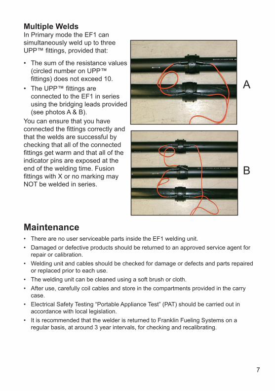
A
B
Multiple WeldsIn Primary mode the EF1 can simultaneously weld up to three UPP™ fittings, provided that:
• The sum of the resistance values (circled number on UPP™ fittings) does not exceed 10.
• The UPP™ fittings are connected to the EF1 in series using the bridging leads provided (see photos A & B).
You can ensure that you have connected the fittings correctly and that the welds are successful by checking that all of the connected fittings get warm and that all of the indicator pins are exposed at the end of the welding time. Fusion fittings with X or no marking may NOT be welded in series.
Maintenance• There are no user serviceable parts inside the EF1 welding unit.• Damaged or defective products should be returned to an approved service agent for
repair or calibration.• Welding unit and cables should be checked for damage or defects and parts repaired
or replaced prior to each use.• The welding unit can be cleaned using a soft brush or cloth.• After use, carefully coil cables and store in the compartments provided in the carry
case.• Electrical Safety Testing “Portable Appliance Test” (PAT) should be carried out in
accordance with local legislation.• It is recommended that the welder is returned to Franklin Fueling Systems on a
regular basis, at around 3 year intervals, for checking and recalibrating.

8
Fault IndicatorsWhen an error has occurred during the weld cycle that will have an effect on the success of the joint, the red warning LED on the right side of the display will light up. Also one of the “weld progress” lights will light up at the same time to show what type of fault has occurred. Error LED
Fault Indicated Meaning Solution
1Power supply failure during weld
The power supply was off at sometime during the weld
• Check and repair power supply• Check plug connection• Check cables are not damaged or
broken• Re-weld fitting only after it is allowed
to cool to ambient temperature
2Stop button pressed during weld
Stop button was pressed
• Re-weld fitting only after it is allowed to cool to ambient temperature
3 Power supply out of limits
Supply frequency not between 40 and 70 Hz, or Voltage not between 194 & 264V
• Check and rectify generator output• Check mains supply• Make sure supply is to required
specification
4Ambient temperature out of range
Temperature of the EF1 is not between -15° C (5º F) and +45° C (113º F)
• Allow EF1 and fitting to cool in the shade
• Wait for ambient temperature to return to range
5No output current (open circuit)
Loose connection to terminal pinLoose contact in the welding circuitFaulty fittingStart button not depressed for long enough
• Make sure connectors are pushed firmly on to terminal pins
• Check welding cable connection and continuity
• Move generator closer and use shorter extension cord
• Replace fitting• See operating sequence, step 5
6 Low output current
Resistance value of fitting is too highToo many fittings connected in series (Primary mode only)Input voltage too low
• Use only UPP™ electrofusion fittings and correct welding cable
• Check resistance codes on fittings - do not exceed a sum total of 10
• Check supply voltage• Check extension leads being used are
to specification
7 High output current
Regulation error in electronics
• Switch off machine and switch on again after 10 seconds.
• Ensure welder is within temperature range
• If problem persists, return EF1 to supplier
The EF1 can be reset after a fault has been remedied by pressing and holding the START / STOP button for 3 seconds.

9
According to the European Directive 2008/34/EC Waste Electrical and Electronic Equipment (WEEE), when no longer suitable for use, this equipment must be separately collected and sent for recycling.
According to the European Directive 2008/35/EC Restriction of Hazardous Substances (RoHS), this equipment does not contain more than the agreed levels of Lead, Cadmium, Mercury, Hexavalent Chromium, Polybrominated Biphenyl (PBB) and Polybrominated Diphenyl Ether (PBDE) flame retardants.
Declaration of ConformityThis welding unit has been designed to comply with the harmonised standards under “New Approach” directives and has been CE Marked accordingly.The applicable standards are:
• 2004/108/EC Electromagnetic compatibility.• 2006/95/EC Low voltage equipment.• 98/37/EC Machinery safety.• 94/62/EC Packaging and packaging waste.• 2008/34/EC Waste electrical and electronic equipment.• 2008/35/EC Restriction of hazardous substances.
Disposal
The equipment and packaging should be sorted for environmentally friendly recycling.
IMPORTANT!Do not dispose of this equipment into household waste.
Andrea Ticci Signed on behalf of Franklin Fueling Systems
RoHS CompliantDirective 2008/ 35/ EC

10
Page intentionally blank

11
Page intentionally blank

©FFS 2014 408001010 Rev4