Embed Size (px)
Citation preview
EELE 3332 – Electromagnetic II
Chapter 12
Waveguide Resonators
Islamic University of Gaza
Electrical Engineering Department
Dr. Talal Skaik
2012 1
Resonance: The tendency of a system to oscillate at maximum
amplitude at a certain frequency.
Microwave resonators are tunable circuits used in microwave
oscillators, filters and frequency meters.
The operation of microwave resonators is very similar to that
of the lumped-element resonators (such as parallel and series
RLC resonant circuits) of circuit theory.
Transmission line sections can be used with various lengths
(nλg/2) and terminations (usually open or short circuited) to
form resonators.
Resonators can be constructed from closed sections of
waveguides.
Dr. Talal Skaik 2012 IUG 2
Resonance
Dr. Talal Skaik 2012 IUG 3
Rectangular Waveguide Cavities
Resonators can be constructed from closed sections of waveguide.
Waveguide resonators are usually short circuited at both ends,
thus forming a closed box or cavity.
Standing waves are formed in the cavity (recall a standing wave is
a combination of two waves travelling in opposite directions).
Electric and magnetic energy is stored within the cavity.

Dr. Talal Skaik 2012 IUG 4
g
2 2 2
To satisfy the boundary conditions, must be equal
to an integer multiple of / 2.
A resonant wave number for the rectangular cavity
can be deifned as:
π π π
The resonant f
mnl
d
m n lk
a b d
2 2 2
requency of the TE or TM mode
is then given by:
1
2
mnl mnl
mnl
m n lf
a b d
Rectangular Waveguide Cavity
Dr. Talal Skaik 2012 IUG 5
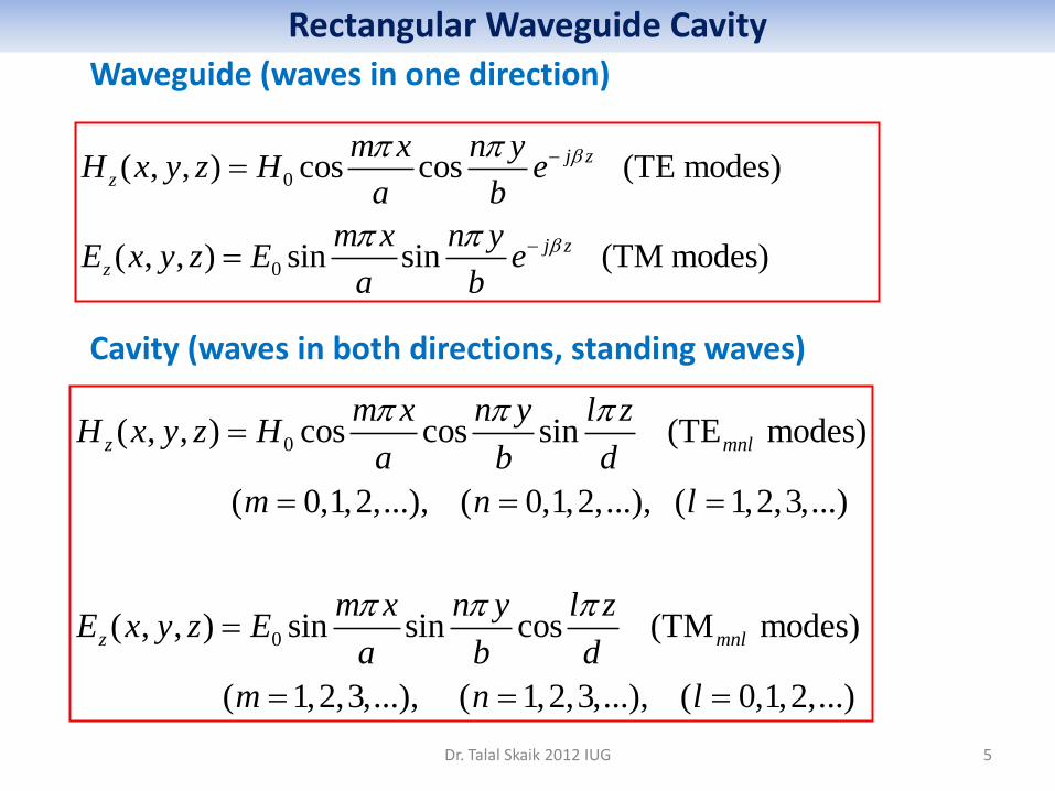
Waveguide (waves in one direction)
Cavity (waves in both directions, standing waves)
0
0
( , , ) cos cos (TE modes)
( , , ) sin sin (TM modes)
j z
z
j z
z
m x n yH x y z H e
a b
m x n yE x y z E e
a b
0
0
( , , ) cos cos sin (TE modes)
( 0,1,2,...), ( 0,1,2,...), ( 1,2,3,...)
( , , ) sin sin cos (TM modes)
( 1,2,3,...), (
z mnl
z mnl
m x n y l zH x y z H
a b d
m n l
m x n y l zE x y z E
a b d
m n
1,2,3,...), ( 0,1,2,...)l
Rectangular Waveguide Cavity
A set of mnl corresponds to a mode, where the indices m,n,l
refer to the number of variations in the standing wave pattern in
the x,y,z directions. TE101 stands for that a rectangular waveguide
cavity operating on a TE10 wave, and the length of the cavity is
half of the guide wavelength.
The lowest order modes in a rectangular cavity are the TM110,
TE101, and TE011 modes. Which of these modes is the dominant
mode depends on the relative dimensions of the resonator. If
b<a<d, the dominant resonant mode is TE101.
In order to properly design the coupling and the tuning devices
of the cavity, knowledge about the distribution of the fields in the
cavity is required. Dr. Talal Skaik 2012 IUG 6
Rectangular Waveguide Cavity

Dr. Talal Skaik 2012 IUG 7
The figure gives the distribution of the fields in a rectangular cavity operating at the TE101 mode. x
z y
x
y
z
b
a
d
Magnetic field lines
Electric field lines
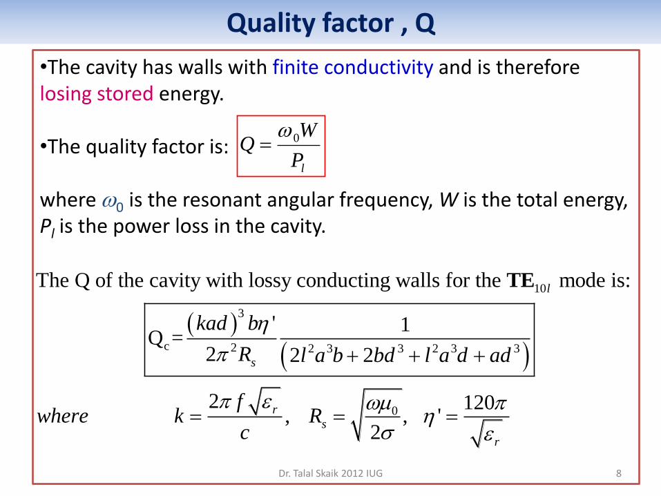
•The cavity has walls with finite conductivity and is therefore losing stored energy. •The quality factor is: where 0 is the resonant angular frequency, W is the total energy, Pl is the power loss in the cavity.
Dr. Talal Skaik 2012 IUG 8
Quality factor , Q
10
3
c 2 2 3 3 2 3 3
0
The Q of the cavity with lossy conducting walls for the mode is:
' 1 Q =
2 2 2
2 120 , , '
2
l
s
r
s
r
kad b
R l a b bd l a d ad
fwhere k R
c
TE
lP
WQ 0
9
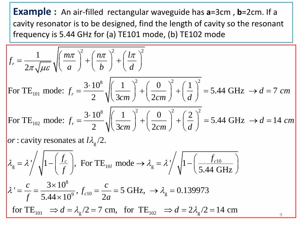
Example : An air-filled rectangular waveguide has a=3cm , b=2cm. If a
cavity resonator is to be designed, find the length of cavity so the resonant frequency is 5.44 GHz for (a) TE101 mode, (b) TE102 mode
2 2 2
2 2 28
101
2 2 28
102
1
2
3 10 1 0 1For TE mode: 5.44 GHz 7
2 3 2
3 10 1 0 2For TE mode: 5.44 GHz 14
2 3 2
: cavi
r
r
r
m n lf
a b d
f d cmcm cm d
f d cmcm cm d
or
g
10g 10 g
8
10 g9
101 g 102 g
ty resonates at /2.
' 1 , For TE mode ' 15.44 GHz
3 10' , 5 GHz, 0.139973
5.44 10 2
for TE /2 7 cm, for TE 2 /2 14 cm
c cl
c
l
f f
f
c cf
f a
d d

Dr. Talal Skaik 2012 IUG 10
For a cavity of dimensions; 5cm x 4cm x 10 cm filled with air and made of copper (c=5.8 x 10⁷)
Find the resonant frequency and the quality factor for the dominant mode.
Example
2 2 2
2 2 210
101
3
0c 2 2 3 3 2 3 3
0
1
2
3 10 1 0 1For TE mode: 3.354 GHz
2 5 4 10
' 21Q = , ,
2 22 2
270.246, 0
2
mnl
r
r
s
s
s
m n lf
a b d
f
kad b fk R
R cl a b bd l a d ad
fk R
c
c
.0151, ' 120
Q = 14365

Dr. Talal Skaik 2012 IUG 11
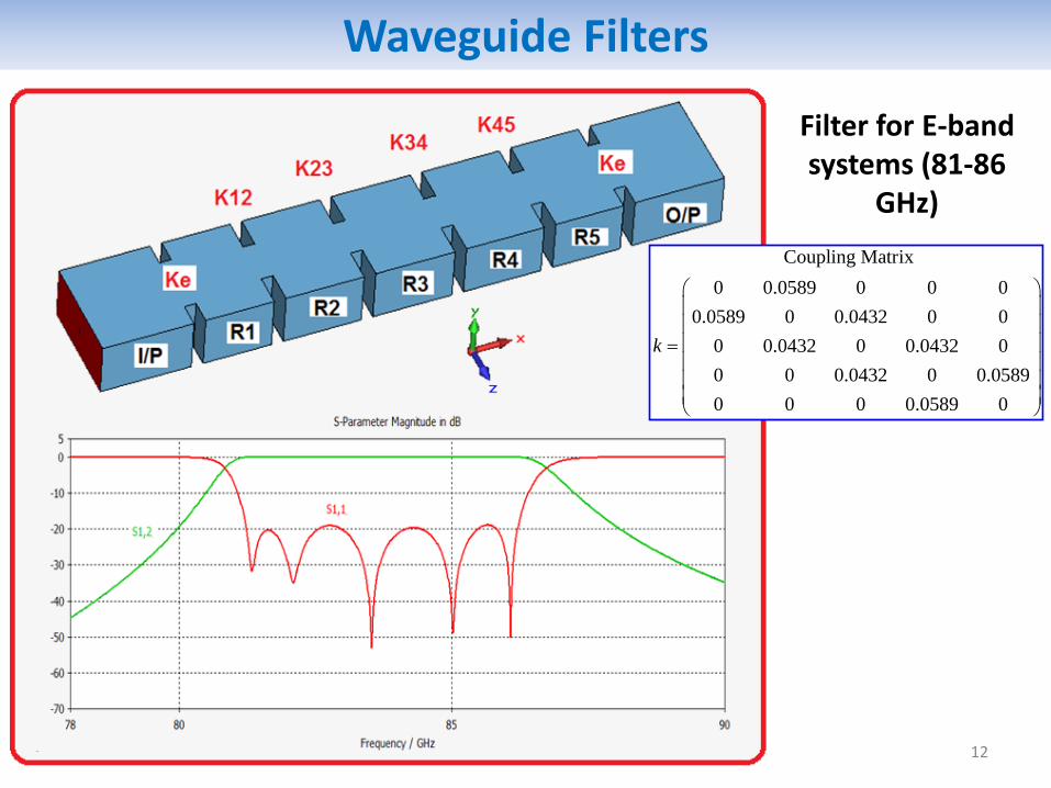
Waveguide Filters
Dr. Talal Skaik 2012 IUG 12
Waveguide Filters
Coupling Matrix
0 0.0589 0 0 0
0.0589 0 0.0432 0 0
0 0.0432 0 0.0432 0
0 0 0.0432 0 0.0589
0 0 0 0.0589 0
k
Filter for E-band systems (81-86
GHz)