Embed Size (px)
Citation preview
DHANALAKSHMI COLLEGE OF ENGINEERING, CHENNAI
DEPARTMENT OF ELECTRONICS AND COMMUNICATION ENGINEERING
EE6201 – CIRCUIT THEORY
UNIT - I : BASIC CIRCUIT ANALYSIS
PART - A (2 MARKS)
1. State Ohm’s law
Ohm’s law states that the voltage (v) across a resistor(R) is directly proportional to the current
(i)flowing through the resistor, at constant temperature.ie, v α i, v = iR,
2. State the Limitation of Ohm’s law (M/J - 13)
1. Ohm’s law doesn’t apply to all non metallic conductors 2. Doesn’t apply to nonlinear devices like
Zener diode, Voltage regulator, tubes etc., 3.It is not applicable for the metallic conductors which
changes with temperature
3. An Electric iron is rated 1000W, 240V. Find the current drawn & resistance of the heating element.
P=V2/R; R= 2402/1000= 57.6Ω and I= V/R =240/57.6 = 4.166 A
4. Define i) charge ii) electric current iii) power iv) network & v) circuit.
Charge: Charge is an electrical property of the atomic particles of which matter consists, measured
in coulombs(C).
Electric current is the time rate of change of charge, measured in amperes (A). i =dq/dt .
A direct current (DC) is a current that remains constant with time. An alternating current (AC) is a
current that varies sinusoid ally with time
Power is the time rate of expending or absorbing energy, measured in watts(w).p = dw/dt,p- Power
in watts (w); w- energy in joules (J); t - time in seconds (S) ;( or) p = v i,v - Voltage in volts (V); i -
current in amperes (A);
Network: The inter connection of two or more simple circuit elements forms an electrical network.
Circuit: If the network contains at least one closed path, it is an electric circuit.
5. State Kirchhoff’s Current law.
KCL (Kirchoff’s Current Law) states that the algebraic sum of currents entering a node (or a closed
boundary) is zero. (or)The sum of the currents entering a node is equal to the sum of the currents
leaving the node.
6. State Kirchoff’sVoltage law. (N/J - 13)
KVL (Kirchoff’s Voltage Law) states that the algebraic sum of all voltages around a closed path (or
loop) is zero. (or) Sum of voltage drop = Sum of voltage rise.
7. The total charge entering a terminal is given by q=5t sin 4πt, mC. Calculate the current at t=0.5
seconds.
Given,Charge q = 5t sin 4πt ( mC) = 5t sin 4πt x 10-3 C; Time, t = 0.5 s
Current, i = q/t = 5t sin 4πt x 10-3/t = 5 sin 4πt x 10-3 = 0.5472 x 10⁻³ ,A i = 0.5472 mA
8. How much energy does a 100W electric bulb consume in two hours?
Power = Energy/Time => Energy = P*t = 100*2*3600 = 720000 = 720 KJ
9. A stove element draws 15 A when connected to a 120V line. How long does it take to consume
30KJ.
Time =
,t=
=
=16.67sec
10.What do you meant by Active elements? Give examples.
The element which is capable of generating or supplying energy is called an Active element.
Example: Generators, Batteries, Operational Amplifiers etc.,
11.What do you mean by passive elements? Give examples.
The Passive elements are those, which are capable only of receiving power. Eg: Inductors and
Capacitors.
12. Define: Node (OR) Junction.
A Node is a point in the network where two or more circuit elements are connected.
13. Define: Tree
A Tree is a complete path including all the nodes.
14. Define: Branch
A branch is a part of the circuit which lies between two junction points.
15.What do you meant by series and parallel circuit?
When circuit elements like resistors are connected in series, such that the same currentpasses
through all of them, then they are said to be in series.When circuit elements are connected across
one another such that the same voltage is applied to each, then the are said to be in parallel.
16.What are the concepts of series circuit?
1. Current flow in all part of the circuit is the same.2. Voltage across the different elements will
depend upon the resistance of the elements3. Voltage drops are additive4. Resistances are
additive5. Powers are additive 6. Applied voltage equals to the sum of different voltage drops.
17. What are the disadvantages of series circuit?
1. If a break occurs at any point in the circuit no current will flow and the entire circuit becomes
useless. 2. Series circuit is not practicable for lighting circuits 3. Electrical devices have a different
current ratings, they cannot be connected in series for efficient operation.
18. Define power and energy. Give the expression for electrical power and energy.
Power is the rate of doing work and its unit is Watt. The unit of electric power is defined interms of
the joule per second. One joule per second is the work done when one coulomb of electricity is
moved through a potential difference of one volt in one second.Power P = EI = I2R = E2/R Watts.
Energy is the product of power and time. If the power remains constant at Pduring the period of
time t seconds, the energy equals Pt Watt-sec or Joules. Energy W = Pt = EIt = I2Rt = E2t/R J.
19. Write down the expression of equivalent resistance for ‘n’ – number of resistors in series
connection.
For ‘n’ resistors connected in series, the equivalent resistance is given
by,Req=R1+R2+R3+………..+Rn
20. Write down the expression of equivalent resistance for ‘n’ - number of resistors in parallel
connection.
For ‘n’ resistors connected in parallel, the equivalent
resistance is given by,
21. Write the Algorithm for Nodal Analysis.
Select a node as the reference node. Assign voltages V1,V2,…Vn-1 to the remaining n-1 nodes.
Apply KCL to each of the n-1 nodes. Solve the resulting simultaneous equations to obtain the
unknown node voltages.
22. Write the Algorithm for Mesh Analysis. (N/D - 12)
RnRRRq
1.........
3
1
2
1
1
1
Re
1
Assign mesh currents i1,i2,….in to the n meshes. Apply KVL to each of the n meshes. Solve the
resulting n simultaneous equations to get the mesh currents.
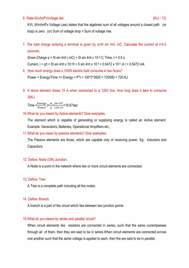
23. Apply KVL and solve the following circuit. Find the value of current I?
By applying KVL, 40-8I+100-2I-30I=0, ans: I=3.5A
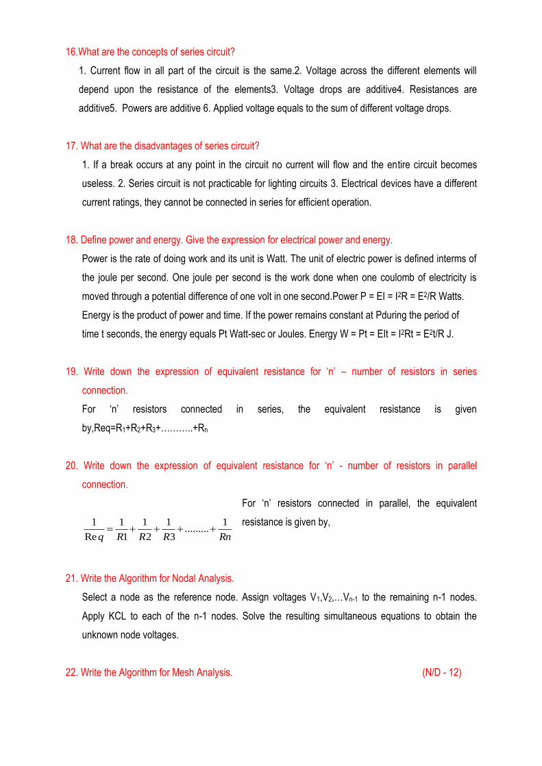
24. Write the Mesh equation for the circuit shown in figure.
25. Distinguish between a Loop & Mesh of a circuit (DEC 2010) (M/J - 13)
The closed path of a network is called a Loop.An elementary form of a loop which cannot be further
divided is called a mesh. In other words Mesh is closed path does not contain an other loop within
it.
26.How are the following affected by change of frequency?a)Resistance b)Inductive reactance.
(N/D - 10)
Resistance will not be affected by change of frequency. Inductive reactance will increase by
increasing frequency and vice versa.
27. State Kirchoff’s law applied to A.C circuits. (M/J - 12)
KCL (Kirchoff’s Current Law) states that the vector sum of currents entering a node (or a
closedboundary) is zero.(or)The vector sum of the currents entering a node is equal to the vector
sum of the currents leaving the node.
KVL (Kirchoff’s Voltage Law) states that the Vector sum of all voltages around a closed path (or
loop) is zero.
28. What are the advantages of node voltage method of solving electrical network? (M/J - 12)
Ans: 7I1 – 2I2 =10
-2I+12I2=0
In the node voltage method it is necessary to recognize the junction nodes in the network with refer
to one junction node the other junction node voltage are assumed as independent variables.
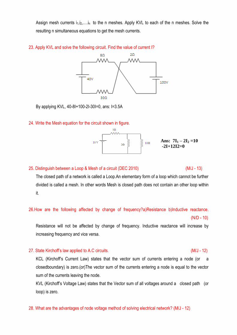
29. Define RMS voltage. (M/J - 14)
The RMS value of an AC is defined as the equivalent steady value of the DC which can produce
the equal amount of heat, when flow through the given circuit for an equal time.
√
RMS value of an AC voltage,
√ =0.707Vm
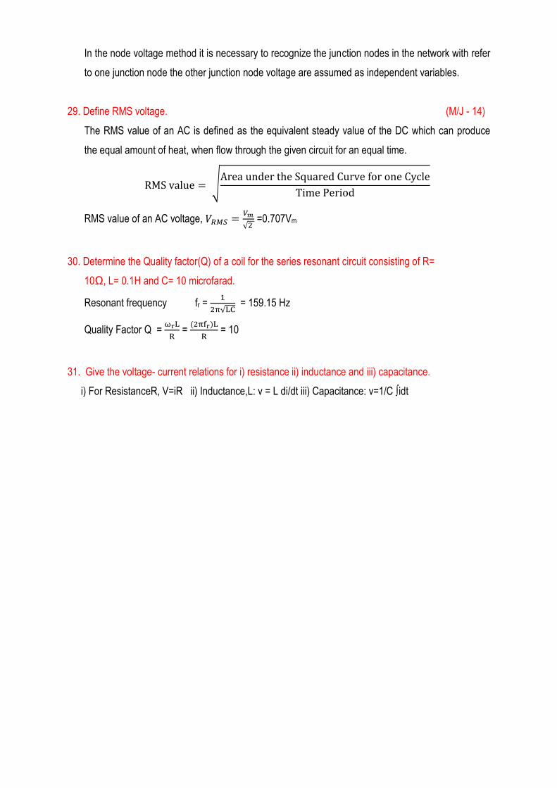
30. Determine the Quality factor(Q) of a coil for the series resonant circuit consisting of R=
10Ω, L= 0.1H and C= 10 microfarad.
Resonant frequency fr =
√ = 159.15 Hz
Quality Factor Q =
=
= 10
31. Give the voltage- current relations for i) resistance ii) inductance and iii) capacitance.
i) For ResistanceR, V=iR ii) Inductance,L: v = L di/dt iii) Capacitance: v=1/C ∫idt
PART – B (16 MARKS)
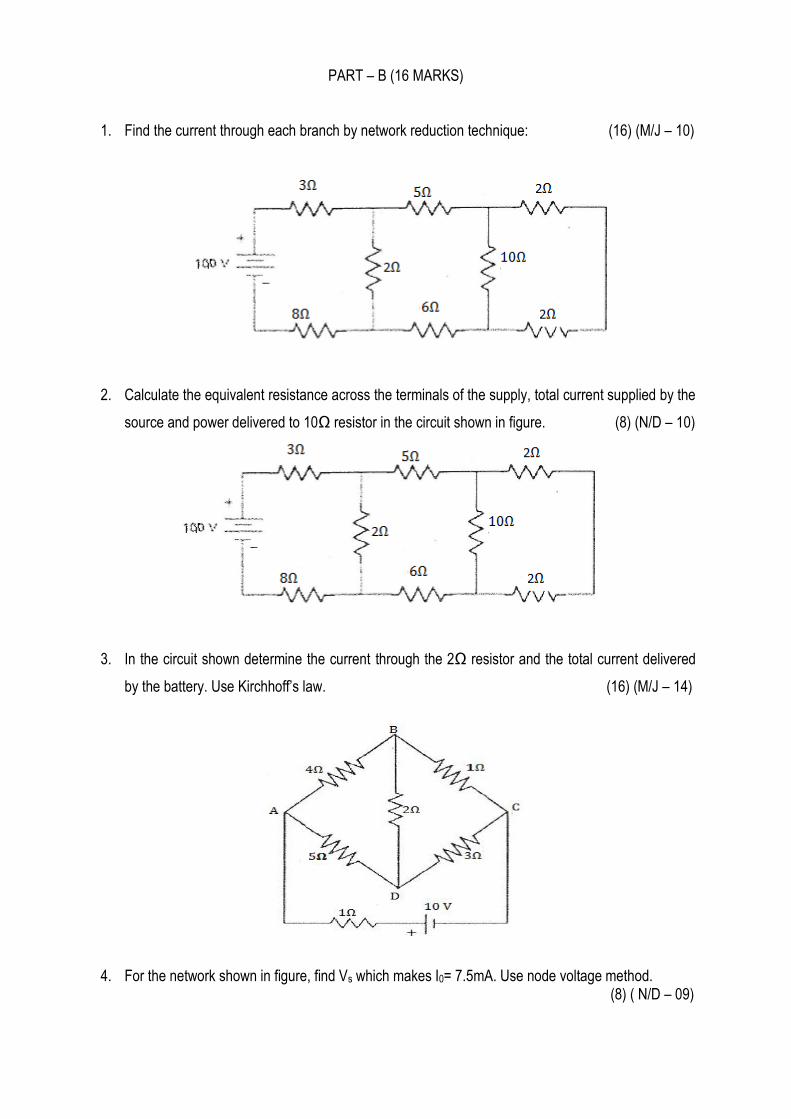
1. Find the current through each branch by network reduction technique: (16) (M/J – 10)
2. Calculate the equivalent resistance across the terminals of the supply, total current supplied by the
source and power delivered to 10Ω resistor in the circuit shown in figure. (8) (N/D – 10)
3. In the circuit shown determine the current through the 2Ω resistor and the total current delivered
by the battery. Use Kirchhoff’s law. (16) (M/J – 14)
4. For the network shown in figure, find Vs which makes I0= 7.5mA. Use node voltage method.
(8) ( N/D – 09)
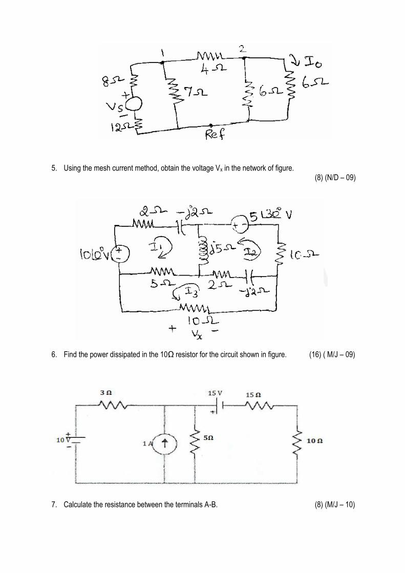
5. Using the mesh current method, obtain the voltage Vx in the network of figure. (8) (N/D – 09)
6. Find the power dissipated in the 10Ω resistor for the circuit shown in figure. (16) ( M/J – 09)
7. Calculate the resistance between the terminals A-B. (8) (M/J – 10)
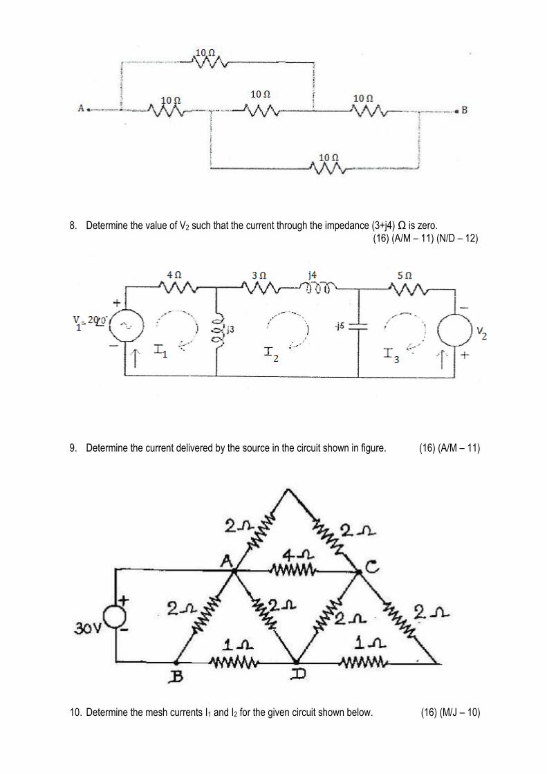
8. Determine the value of V2 such that the current through the impedance (3+j4) Ω is zero.
(16) (A/M – 11) (N/D – 12)
9. Determine the current delivered by the source in the circuit shown in figure. (16) (A/M – 11)
10. Determine the mesh currents I1 and I2 for the given circuit shown below. (16) (M/J – 10)
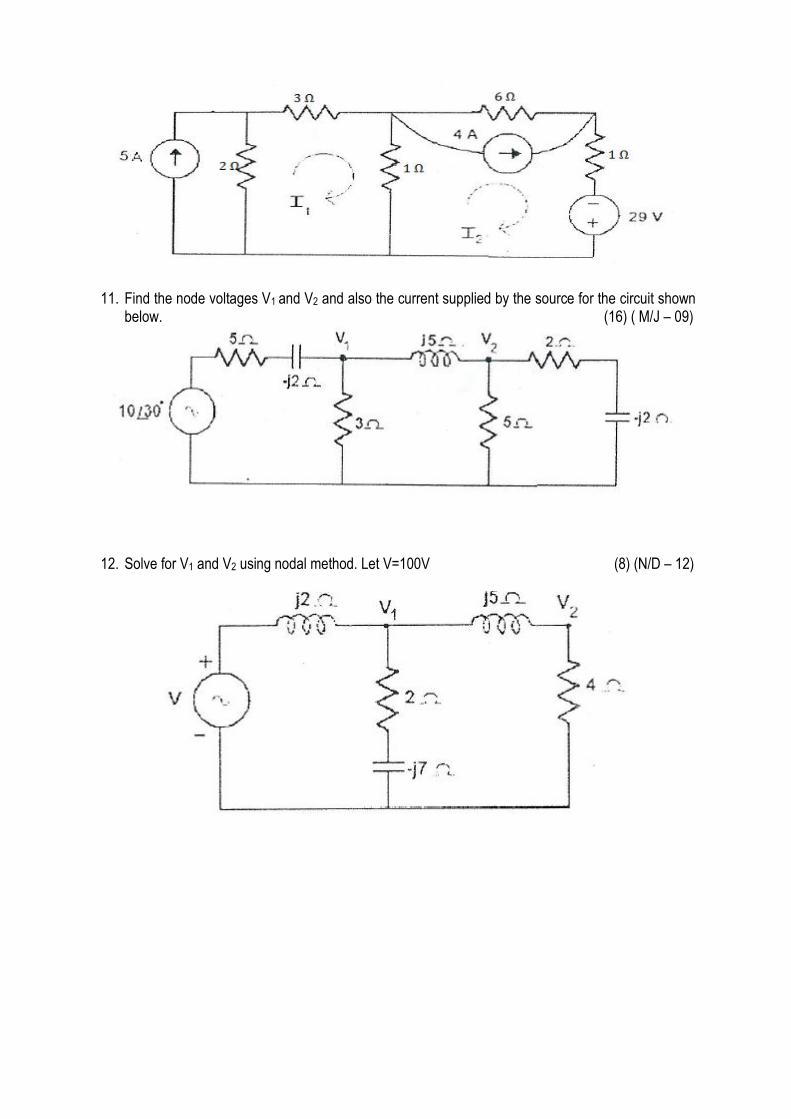
11. Find the node voltages V1 and V2 and also the current supplied by the source for the circuit shown
below. (16) ( M/J – 09)
12. Solve for V1 and V2 using nodal method. Let V=100V (8) (N/D – 12)
UNIT - II : NETWORK REDUCTION AND NETWORK THEOREMS FOR DC&AC CIRCUITS
PART - A (2 MARKS)
1. Define Lumped circuit.
The circuit in which the elements are separated physically like resistors, capacitors and inductors.
2. State division of current rule for a two branch parallel network. (M/J - 13, N/D - 13)
R1 and R2 are connected in parallel, Let I be the total current, I1 be the current through R1, I2 be the
current through R2.Then I1 = I * R2/(R1+R2); I2 = I * R1/(R1+R2)
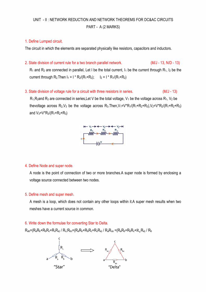
3. State division of voltage rule for a circuit with three resistors in series. (M/J - 13)
R1,R2and R3 are connected in series,Let V be the total voltage, V1 be the voltage across R1, V2 be
thevoltage across R2,V3 be the voltage across R3.Then,V1=V*R1/(R1+R2+R3),V2=V*R2/(R1+R2+R3)
and V3=V*R3/(R1+R2+R3)
4. Define Node and super node.
A node is the point of connection of two or more branches.A super node is formed by enclosing a
voltage source connected between two nodes.
5. Define mesh and super mesh.
A mesh is a loop, which does not contain any other loops within it.A super mesh results when two
meshes have a current source in common.
6. Write down the formulae for converting Star to Delta.
Rab=(RaRb+RbRc+RcRa) / Rc;Rbc=(RaRb+RbRc+RcRa) / RaRca =(RaRb+RbRc+ Ra) / Rb
7. State Superposition theorem.
The superposition theorem states that in any linear network containing two or more sources, the
response in any element is equal to algebraic sum of the responses caused by individual sources
acting alone, while the other sources are non operative; that is, while considering the effect of
individual sources, other ideal voltage sources and ideal current sources in the network are replaced
by short circuit and open circuit across their terminals.
8. What is the limitation of Super Position Theorem.
Super position theorem can be applied for finding the current through or voltage across a particular
element in a linear circuit containing more than two sources. But this theorem cannot be used for the
calculation of the power.
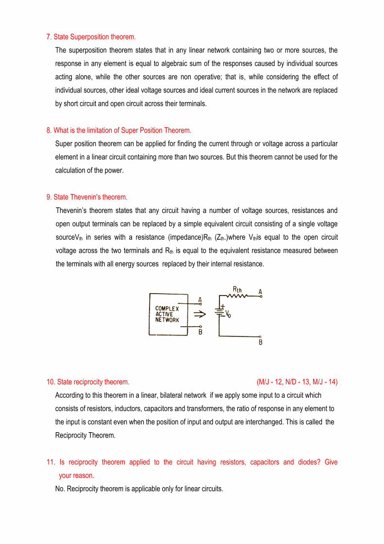
9. State Thevenin's theorem.
Thevenin’s theorem states that any circuit having a number of voltage sources, resistances and
open output terminals can be replaced by a simple equivalent circuit consisting of a single voltage
sourceVth in series with a resistance (impedance)Rth (Zth.)where Vthis equal to the open circuit
voltage across the two terminals and Rth is equal to the equivalent resistance measured between
the terminals with all energy sources replaced by their internal resistance.
10. State reciprocity theorem. (M/J - 12, N/D - 13, M/J - 14)
According to this theorem in a linear, bilateral network if we apply some input to a circuit which
consists of resistors, inductors, capacitors and transformers, the ratio of response in any element to
the input is constant even when the position of input and output are interchanged. This is called the
Reciprocity Theorem.
11. Is reciprocity theorem applied to the circuit having resistors, capacitors and diodes? Give
your reason.
No. Reciprocity theorem is applicable only for linear circuits.
12. State Maximum power transfer theorem. (M/J - 13, M/J - 14)
For a given Thevenin equivalent circuit, maximum power transfer occurs when RL = RTH, that is,
when the load resistance is equal to the thevenin resistance.
13.Write the objectives of star delta transformation? ( N/D - 13)
The star delta transformation is useful in reducing the complexity of a circuit and converts it into
simpler equivalent form without altering the current and voltage levels at its network terminals as
in the original circuits.
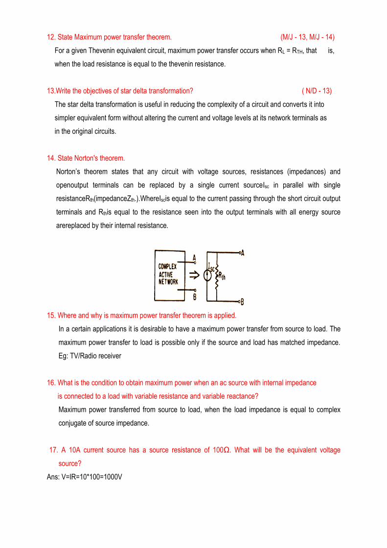
14. State Norton's theorem.
Norton’s theorem states that any circuit with voltage sources, resistances (impedances) and
openoutput terminals can be replaced by a single current sourceIsc in parallel with single
resistanceRth(impedanceZth.).WhereIscis equal to the current passing through the short circuit output
terminals and Rthis equal to the resistance seen into the output terminals with all energy source
arereplaced by their internal resistance.
15. Where and why is maximum power transfer theorem is applied.
In a certain applications it is desirable to have a maximum power transfer from source to load. The
maximum power transfer to load is possible only if the source and load has matched impedance.
Eg: TV/Radio receiver
16. What is the condition to obtain maximum power when an ac source with internal impedance
is connected to a load with variable resistance and variable reactance?
Maximum power transferred from source to load, when the load impedance is equal to complex
conjugate of source impedance.
17. A 10A current source has a source resistance of 100Ω. What will be the equivalent voltage
source?
Ans: V=IR=10*100=1000V
18. A 1V Voltage source has an internal resistance of 1Ω, Calculate the Maximum power that
can be delivered to any load.
Maximum power transferred to the load = Vs2RL / ( Rs+ RL)2= ¼ =0.25 W.
19. State the maximum power transfer theorem for AC circuit.
Maximum average power is transferred to a load when the load impedance is the complex
conjugate of the Thevenin’s impedance as seen from the load terminals, ZL = ZTh*
20. Determine the voltages V1 and V2 in the circuit shown in fig.
21. What is the equivalent resistance across A – B in the network shown in figure?
=5+
=7Ω
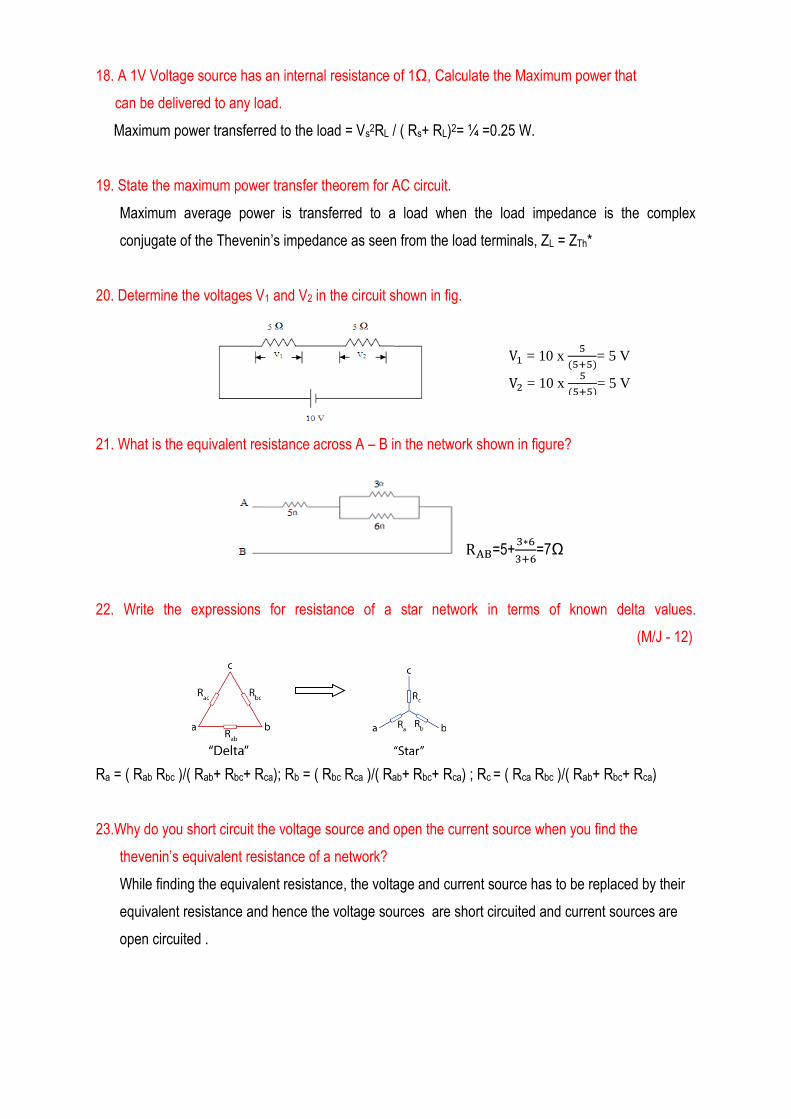
22. Write the expressions for resistance of a star network in terms of known delta values.
(M/J - 12)
Ra = ( Rab Rbc )/( Rab+ Rbc+ Rca); Rb = ( Rbc Rca )/( Rab+ Rbc+ Rca) ; Rc = ( Rca Rbc )/( Rab+ Rbc+ Rca)
23.Why do you short circuit the voltage source and open the current source when you find the
thevenin’s equivalent resistance of a network?
While finding the equivalent resistance, the voltage and current source has to be replaced by their
equivalent resistance and hence the voltage sources are short circuited and current sources are
open circuited .
V = 10 x
= 5 V
V = 10 x
= 5 V
PART – B (16 MARKS)
NETWORK REDUCTION ANDNETWORK THEOREMS FOR DC AND AC CIRCUITS
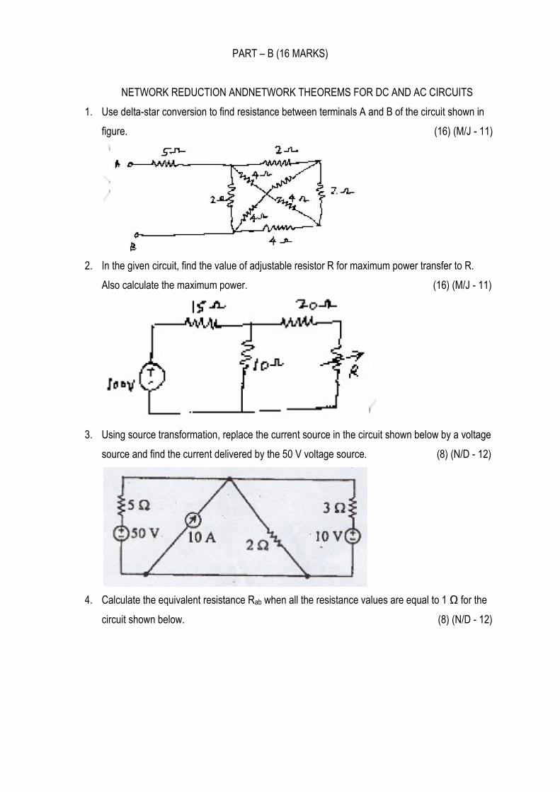
1. Use delta-star conversion to find resistance between terminals A and B of the circuit shown in
figure. (16) (M/J - 11)
2. In the given circuit, find the value of adjustable resistor R for maximum power transfer to R.
Also calculate the maximum power. (16) (M/J - 11)
3. Using source transformation, replace the current source in the circuit shown below by a voltage
source and find the current delivered by the 50 V voltage source. (8) (N/D - 12)
4. Calculate the equivalent resistance Rab when all the resistance values are equal to 1 Ω for the
circuit shown below. (8) (N/D - 12)
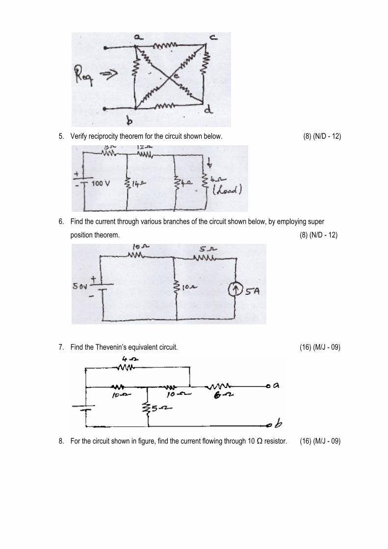
5. Verify reciprocity theorem for the circuit shown below. (8) (N/D - 12)
6. Find the current through various branches of the circuit shown below, by employing super
position theorem. (8) (N/D - 12)
7. Find the Thevenin’s equivalent circuit. (16) (M/J - 09)
8. For the circuit shown in figure, find the current flowing through 10 Ω resistor. (16) (M/J - 09)
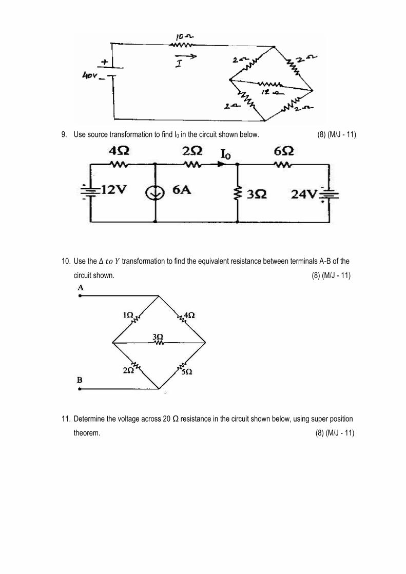
9. Use source transformation to find I0 in the circuit shown below. (8) (M/J - 11)
10. Use the transformation to find the equivalent resistance between terminals A-B of the
circuit shown. (8) (M/J - 11)
11. Determine the voltage across 20 Ω resistance in the circuit shown below, using super position
theorem. (8) (M/J - 11)
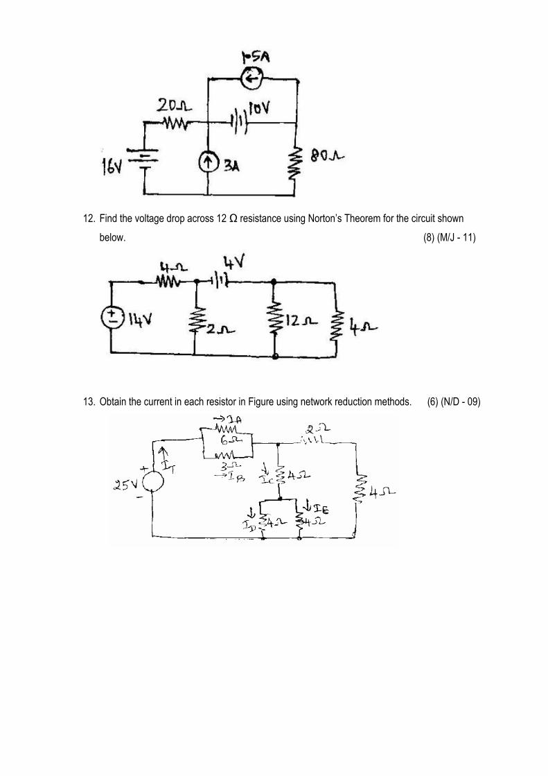
12. Find the voltage drop across 12 Ω resistance using Norton’s Theorem for the circuit shown
below. (8) (M/J - 11)
13. Obtain the current in each resistor in Figure using network reduction methods. (6) (N/D - 09)
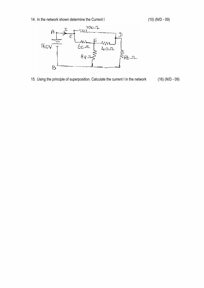
14. In the network shown determine the Current I (10) (N/D - 09)
15. Using the principle of superposition. Calculate the current I in the network (16) (N/D - 09)
UNIT – III : RESONANCE AND COUPLED CIRCUITS
PART - A (2 MARKS)
1. Define Impedance.
Impedance is defined as the opposition of circuit to flow of alternating current. It is denoted by Z and
its unit is ohms.
2. Define Resonance.
Resonance is defined as a phenomenon in which applied voltage and resulting current are in-phase.
In other words, an AC circuit is said to be in resonance if it exhibits unity power factor
condition, that means applied voltage and resulting current are in phase.
3. Define Q - factor or Figure of Merit, Q. (M/J - 14)
The quality factor, Q of a resonant circuit is the ratio of its resonant frequency to its bandwidth.
The Q - factor of a circuit can also be defined as,
Q = circuit in the cycleper dissipatedEnergy
circuit in the storedenergy Maximum 2
4. Show that in a series RLC circuit, f1f2 = fr2 where fr is the resonant frequency and f1, f2 are the half
power frequencies.
=-
√(
)
√(
)
=
=
5. Define Conductance.
It is defined as the ratio of the resistance to the square of the impedance. It is measured in the unit
Siemens and it is denoted by G.G=
6. Define Susceptance.
It is defined as the ratio of the reactance to the square of the impedance. It is measured in the unit
Siemens and it is denoted by B.
7. What is a resonant frequency?
The frequency at which resonance occurs is called resonant frequency. i.e. X L=XC.
8. What are the resonant conditions?
i) The total impedance Z is minimum and is equal to R.ii) The circuit will be purely resistive circuit.iii)
Power factor of the circuit is unity.iv) Circuit element, Imax= V/R.v) Power at resonance, Pr= R.
9. What is the series resonance?
The inductive reactance increases as the frequency increases (XL=ωL) but the capacitive
reactances decreases with frequency(XC=1/ωC). Thus inductive and capacitive reactances have
opposite properties. So, for any LC combination there must be one frequency at which .
This case of equal and opposite reactance is called series resonance.
10. What is a parallel resonance?
The parallel circuit is said to be in resonance, when the power factor is unity. This is true when the
imaginary part of the total admittance is zero.
11. Define Bandwidth, half power frequencies? (M/J - 13)
The difference between the half power frequencies f1 and f2 at which power is half of its maximum is
called bandwidth B.W= f2-f1. It can be observed that at two frequencies f1 and f2 the power is half of
its maximum value. These frequencies are called half power frequencies. Out of the two half power
frequencies, the frequency f2 is called upper cut-off frequency while the frequency f1is called lower
cut-off frequency.
12. Define Selectivity.
The term selectivity is defined as the ratio of the resonant frequency to the bandwidth. Selectivity =
fr/B.W.
13. What are coupled circuits?
The two circuits are said to be coupled circuits if all or part of the electrical energy supplied to one
circuit is transferred to the other circuit, without having any electrical connection between them
14. Define self Inductance.
The property of the coil which opposes any change in current passing through it is called self
inductance of the coil. L = N/I
15. What is meant by Mutual Induction?
When two inductors (or coils) are in a close proximity to each other, the magnetic flux caused by
current in one coil links with the other coil, thereby inducing voltage in the latter. This phenomenon
is known as ‘Mutual Induction’.M =
=
16. Define Mutual Inductance M.
Mutual Inductance is the ability of one inductor to induce a voltage across a neighboring inductor,
measured in henrys (H).
17. State Dot convention.
(i) If a current enters the dotted terminal of one coil, the reference polarity of the mutual voltage in
the second coil is positive at the dotted terminal of the second coil. (ii) If a current leaves the
dotted terminal of one coil, the reference polarity of the mutual voltage in the second coil is negative
at the dotted terminal of the second coil.
18. Write the total inductance of two coils connected in series aiding and opposing.
Series - aiding connection : Leq = L1 + L2 + 2M
Series - opposing connection :Leq = L1 + L2 - 2M
19. Define Coefficient of coupling, K. (M/J - 12, N/D - 13)
The fraction of the total flux produced by one coil linking a second coil is called the Coefficient of
coupling, K.Thus, K = Ф12 / Ф1 = Ф21/ Ф2 K= M/L1L2
Since Ф12< Ф1 or Ф21<Ф2, the value of K is always less than or equal to 1.
20. Two inductively coupled coils have self - inductances L1 = 50 mH and L2 = 200 mH. If the coefficient
of coupling is 0.5 (i) find the value of mutual inductance between the coils, and
(ii) what is the maximum possible mutual inductance?
(i) M = K 21LL = 0.5 (ii) M is max when K=1.M = 21LL =33 102001050 =100mH
21. Two coils connected in series have an equivalent inductance of 0.4H when connected in aiding, and
an equivalent inductance of 0.2H when the connection is opposite. Calculate the
mutual inductance of the coils.
Series aiding, Leq = L1 + L2 + 2M = 0.4 ---------------- (1)
Series opposing, Leq = L1 + L2 - 2M = 0.2 ----------------- (2)
Solving equations (1) and (2), 4M = 0.2; M = 0.05 H
22. What is the relation between the mutual inductance and self-inductance of coils?
(M/J - 14)
M = K21LL where M –Mutual inductance; L1,L2 – self inductance and K – coefficient of
Coupling
23. State dot rule.
The sign of the mutual induced voltage depends on direction of the winding of the coil. For
convenient, dot conventions are used for purpose of indicating direction of winding.
Rules for dot convention:
If a current enters a dot in one coil, then mutually induced voltage is positive at the dotted end.
If a current leaves a dot in one coil, then mutually induced voltage is negative at the dotted end.
24. What are the application of tuned circuits. (M/J - 13)
Tuned circuits are used in communication systems, Radio receivers, in defence
25. Define an ideal transformer.
An ideal transformer is a transformer with no losses and having a core with infinite permeability,
which results in perfect coupling with no leakage flux.
26. A series RLC circuit has a resonant frequency of 12KHz. If R= 5 Ω and X1 at resonance is 300 Ω
Find the Bandwidth. (N/D - 13)
B.W = fr R/X1 = 12* 103 * 5/ 300 = 200Hz.
27. Determine the power factor of a RLC series circuit with R=5ohm, XL=8ohm and XC=12ohm.
(M/J - 12)
√
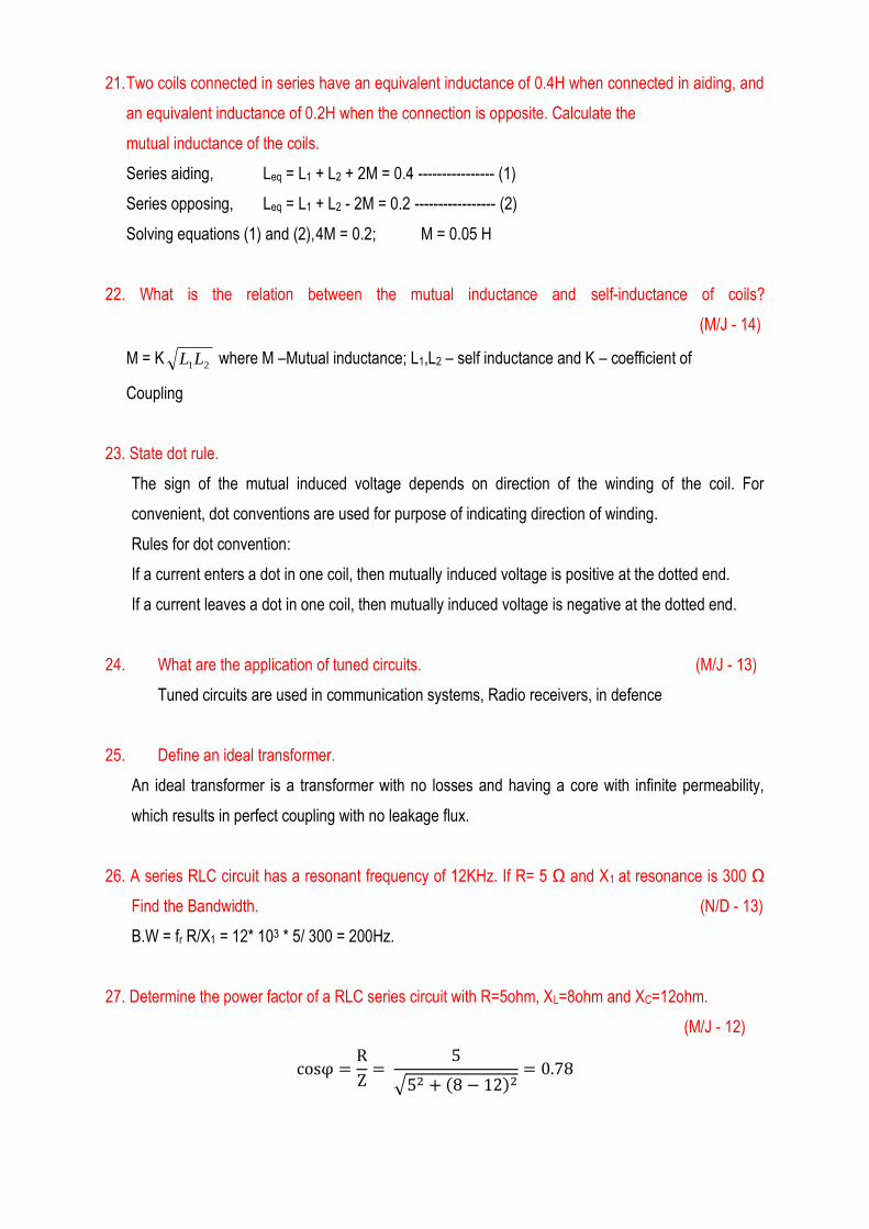
28. Draw the frequency response of RLC series circuit.
29. Write the Significance of Quality factor? (N/D - 13)
The relation between bandwidth and quality factor is Q=Resonant frequency/Bandwidth. This
indicates a higher value of Q results in a smaller bandwidth and hence greater the selectivity. This
indicates the resonant circuit responds to a certain frequency and eliminates all other frequency.
PART – B (16 MARKS)
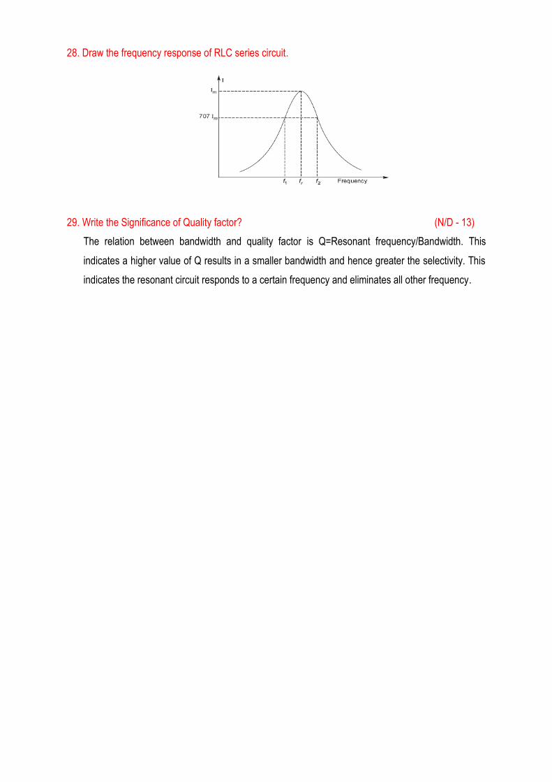
1. For the circuit shown in Fig 1, determine the impedance at resonant frequency, 10Hz above resonant
frequency and 10Hz below resonant frequency. (16) (M/J – 14)
Fig 1
2. Explain that how to derive Q factor of parallel resonance. (16) (M/J – 14)
3. A RLC series circuit consists of R=16Ω, L=15mH and C=2µF. calculate the quality factor at resonance,
bandwidth and half-power frequencies. (8) (M/J – 14)
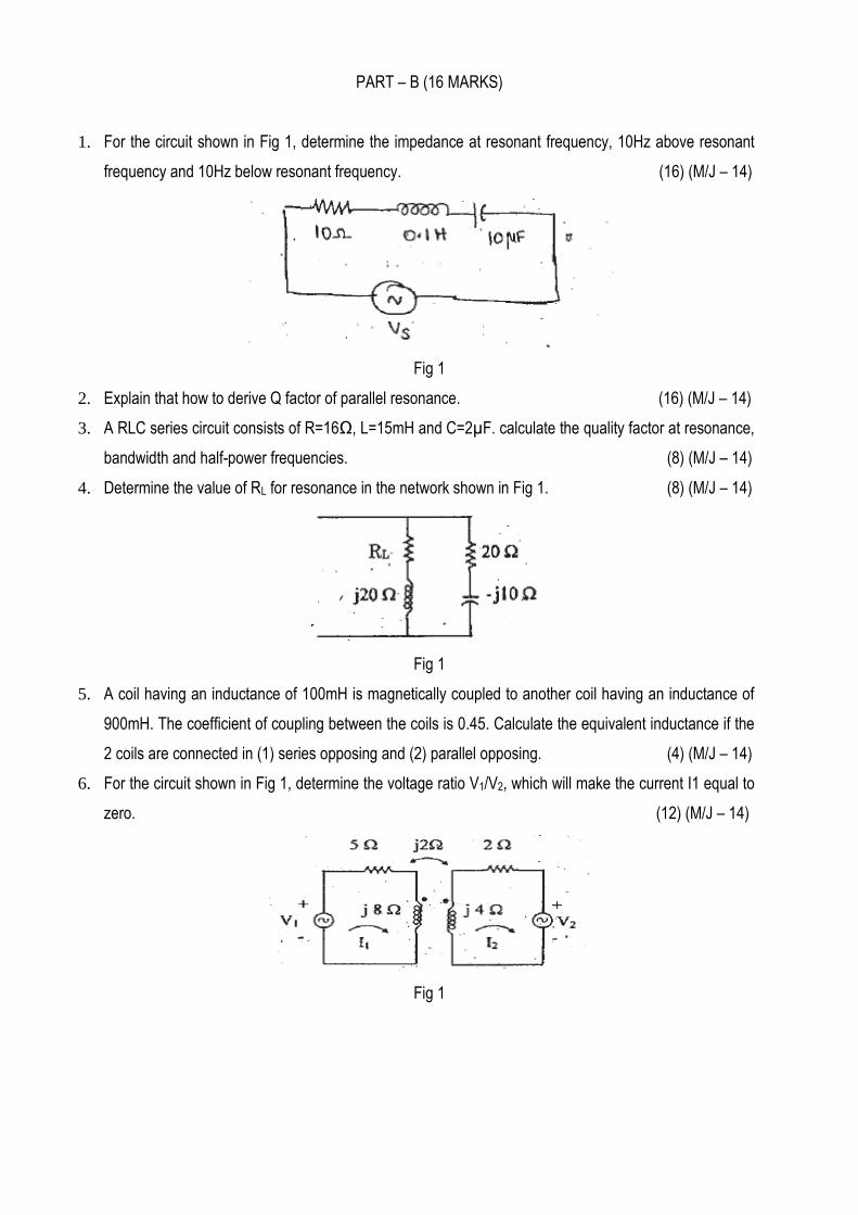
4. Determine the value of RL for resonance in the network shown in Fig 1. (8) (M/J – 14)
Fig 1
5. A coil having an inductance of 100mH is magnetically coupled to another coil having an inductance of
900mH. The coefficient of coupling between the coils is 0.45. Calculate the equivalent inductance if the
2 coils are connected in (1) series opposing and (2) parallel opposing. (4) (M/J – 14)
6. For the circuit shown in Fig 1, determine the voltage ratio V1/V2, which will make the current I1 equal to zero. (12) (M/J – 14)
Fig 1
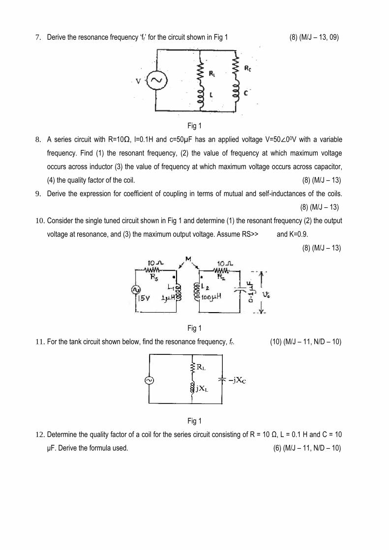
7. Derive the resonance frequency ‘fr’ for the circuit shown in Fig 1 (8) (M/J – 13, 09)
Fig 1
8. A series circuit with R=10Ω, l=0.1H and c=50µF has an applied voltage V=50 00V with a variable
frequency. Find (1) the resonant frequency, (2) the value of frequency at which maximum voltage
occurs across inductor (3) the value of frequency at which maximum voltage occurs across capacitor,
(4) the quality factor of the coil. (8) (M/J – 13)
9. Derive the expression for coefficient of coupling in terms of mutual and self-inductances of the coils.
(8) (M/J – 13)
10. Consider the single tuned circuit shown in Fig 1 and determine (1) the resonant frequency (2) the output
voltage at resonance, and (3) the maximum output voltage. Assume RS>> and K=0.9.
(8) (M/J – 13)
Fig 1
11. For the tank circuit shown below, find the resonance frequency, fr. (10) (M/J – 11, N/D – 10)
Fig 1
12. Determine the quality factor of a coil for the series circuit consisting of R = 10 Ω, L = 0.1 H and C = 10
μF. Derive the formula used. (6) (M/J – 11, N/D – 10)
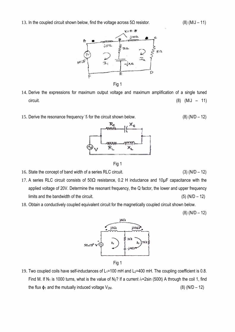
13. In the coupled circuit shown below, find the voltage across 5Ω resistor. (8) (M/J – 11)
Fig 1
14. Derive the expressions for maximum output voltage and maximum amplification of a single tuned
circuit. (8) (M/J – 11)
15. Derive the resonance frequency ‘fr’ for the circuit shown below. (8) (N/D – 12)
Fig 1
16. State the concept of band width of a series RLC circuit. (3) (N/D – 12)
17. A series RLC circuit consists of 50Ω resistance, 0.2 H inductance and 10µF capacitance with the
applied voltage of 20V. Determine the resonant frequency, the Q factor, the lower and upper frequency
limits and the bandwidth of the circuit. (5) (N/D – 12)
18. Obtain a conductively coupled equivalent circuit for the magnetically coupled circuit shown below.
(8) (N/D – 12)
Fig 1
19. Two coupled coils have self-inductances of L1=100 mH and L2=400 mH. The coupling coefficient is 0.8.
Find M. If N1 is 1000 turns, what is the value of N2? If a current i1=2sin (500t) A through the coil 1, find
the flux ϕ1 and the mutually induced voltage V2M. (8) (N/D – 12)
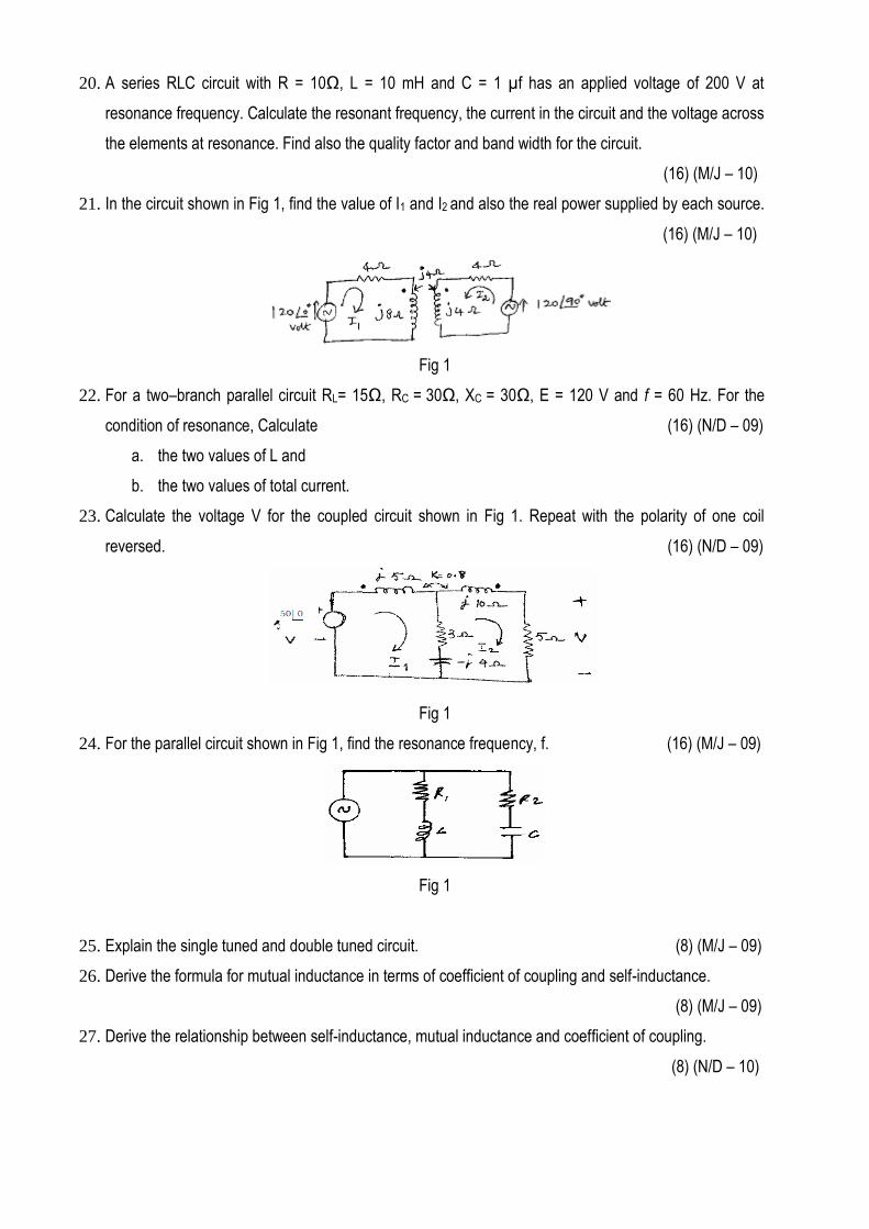
20. A series RLC circuit with R = 10Ω, L = 10 mH and C = 1 µf has an applied voltage of 200 V at
resonance frequency. Calculate the resonant frequency, the current in the circuit and the voltage across
the elements at resonance. Find also the quality factor and band width for the circuit.
(16) (M/J – 10)
21. In the circuit shown in Fig 1, find the value of I1 and I2 and also the real power supplied by each source.
(16) (M/J – 10)
Fig 1
22. For a two–branch parallel circuit RL= 15Ω, RC = 30Ω, XC = 30Ω, E = 120 V and f = 60 Hz. For the
condition of resonance, Calculate (16) (N/D – 09)
a. the two values of L and
b. the two values of total current.
23. Calculate the voltage V for the coupled circuit shown in Fig 1. Repeat with the polarity of one coil
reversed. (16) (N/D – 09)
Fig 1
24. For the parallel circuit shown in Fig 1, find the resonance frequency, f. (16) (M/J – 09)
Fig 1
25. Explain the single tuned and double tuned circuit. (8) (M/J – 09)
26. Derive the formula for mutual inductance in terms of coefficient of coupling and self-inductance.
(8) (M/J – 09)
27. Derive the relationship between self-inductance, mutual inductance and coefficient of coupling.
(8) (N/D – 10)
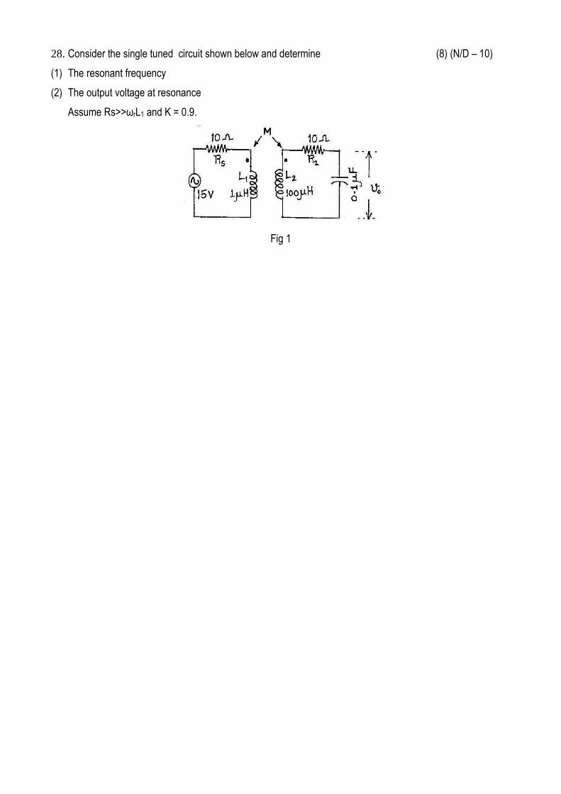
28. Consider the single tuned circuit shown below and determine (8) (N/D – 10)
(1) The resonant frequency
(2) The output voltage at resonance
Assume Rs>>ωrL1 and K = 0.9.
Fig 1
UNIT - IV : TRANSIENT RESPONSE FOR DC CIRCUITS
PART - A (2 MARKS)
1. Define the term time constant of a circuit.
In a circuit in which the current is increasing to a final steady value, the time (T) taken to reach
63.2% of the final value is called the time constant of the circuit.
2. Define time constant of a decaying circuit.
For a decaying circuit, the time constant is defined as the time required to reach 36.8% of the
initial value.
3. Write down the voltage equation of a series RLC transient circuit excited by a dc source, E.
Applying KVL to the circuit, the voltage equation becomes,
EidtCdt
diLRi
1
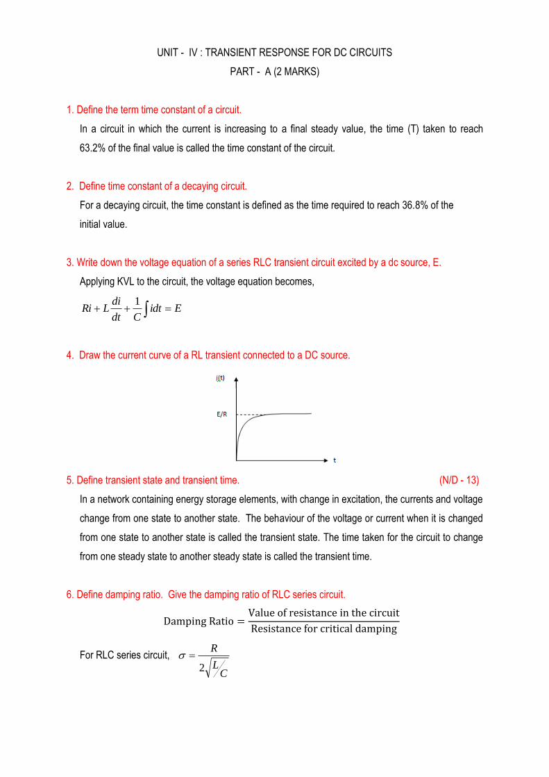
4. Draw the current curve of a RL transient connected to a DC source.
5. Define transient state and transient time. (N/D - 13)
In a network containing energy storage elements, with change in excitation, the currents and voltage
change from one state to another state. The behaviour of the voltage or current when it is changed
from one state to another state is called the transient state. The time taken for the circuit to change
from one steady state to another steady state is called the transient time.
6. Define damping ratio. Give the damping ratio of RLC series circuit.
V
For RLC series circuit,
CL
R
2
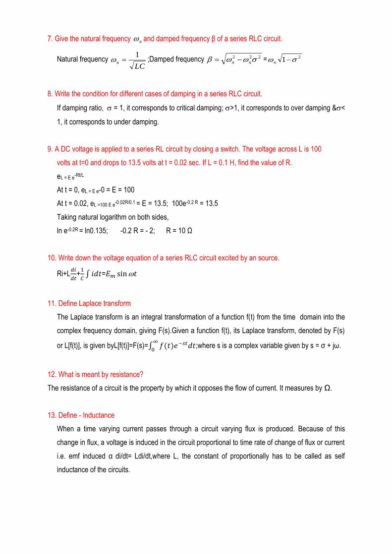
7. Give the natural frequency n and damped frequency β of a series RLC circuit.
Natural frequency LC
n
1 ;Damped frequency 222 nn = 21 n
8. Write the condition for different cases of damping in a series RLC circuit.
If damping ratio, = 1, it corresponds to critical damping; >1, it corresponds to over damping &<
1, it corresponds to under damping.
9. A DC voltage is applied to a series RL circuit by closing a switch. The voltage across L is 100
volts at t=0 and drops to 13.5 volts at t = 0.02 sec. If L = 0.1 H, find the value of R.
eL = E e-Rt/L
At t = 0, eL = E e-0 = E = 100
At t = 0.02, eL =100 E e-0.02R/0.1 = E = 13.5; 100e-0.2 R = 13.5
Taking natural logarithm on both sides,
ln e-0.2R = ln0.135; -0.2 R = - 2; R = 10 Ω
10. Write down the voltage equation of a series RLC circuit excited by an source.
Ri+L
+
∫ =
11. Define Laplace transform
The Laplace transform is an integral transformation of a function f(t) from the time domain into the
complex frequency domain, giving F(s).Given a function f(t), its Laplace transform, denoted by F(s)
or L[f(t)], is given byL[f(t)]=F(s)=∫
;where s is a complex variable given by s = σ + jω.
12. What is meant by resistance?
The resistance of a circuit is the property by which it opposes the flow of current. It measures by Ω.
13. Define - Inductance
When a time varying current passes through a circuit varying flux is produced. Because of this
change in flux, a voltage is induced in the circuit proportional to time rate of change of flux or current
i.e. emf induced α di/dt= Ldi/dt,where L, the constant of proportionally has to be called as self
inductance of the circuits.
14. Define – Capacitance
A capacitor is a circuit element that, like the inductor, stores energy during periods of time and
returns the energy during others. In the capacitor, storage takes place in an electric field unlike the
inductance where storage is in a magnetic field.
15. Define Natural response or source free response. (M/J - 14)
The response of the circuit due to the stored energy in the circuit elements (independent of sources)
is called natural response.
16. Define forced response. (M/J - 14)
The response of the circuit due to the external source is called forced response
17. Define the term Rise time (tr) & Delay time (td).
The time taken by the response to reach 100% of the steady state value for the first time is known
as Rise time.
The time taken by the response to reach 50% of the steady state value for the first time is known as
Delay time.
18. Draw the transient response of a first order circuit with a forcing function.
19. Define transient response.
The response or the output of the circuit from the instant of switching tothe attainment of steady
state is known as transient response.
20. Define the time constant of RL circuit. (M/J - 12, M/J - 14)
Time constant of RL circuit is defined as time taken to reach 63.2% of final value (steady
state)
21. In circuits excited by DC source when there is no stored energy at initial state, capacitance
behaves as short circuit and Inductance behave as open circuit. (M/J - 12)
22. Find the Time constant of RL circuit having
i)R = 10Ω and L= 0.1 mH(M/J - 13)
Ans: Time constant (L/R)=(.1*10^-3/10)=10 µSec
ii)R=10ohms and L=20mH(M/J - 14)
Ans: Time constant (L/R)=(20*10^-3/10)=2 mSec
23. A RLC circuit has R=10Ω, L=2H.What value of capacitance will make the circuit critically
damped? (M/J - 13)
(
)
=
; C=0.08F
24. Distinguish between natural and forced response.
Natural Response Forced Response
It is determined by the internal energy stored
in the network
It is determined by the application of external
energy source
Voltage source and current source are not
present.
Voltage and current sources are present
25. Write the purpose of Laplace transformation in the circuit analysis. (N/D - 13)
To simplify complex exponential and trigonometric functions into simple algebraic functions.
To simplify differential and integral operations by transforming into simple multiplication and
division.
To obtain complete solution including arbitrary constants for differential equations.
To obtain response for any input for a given system, if step and impulse responses are known.
PART – B (16 MARKS)
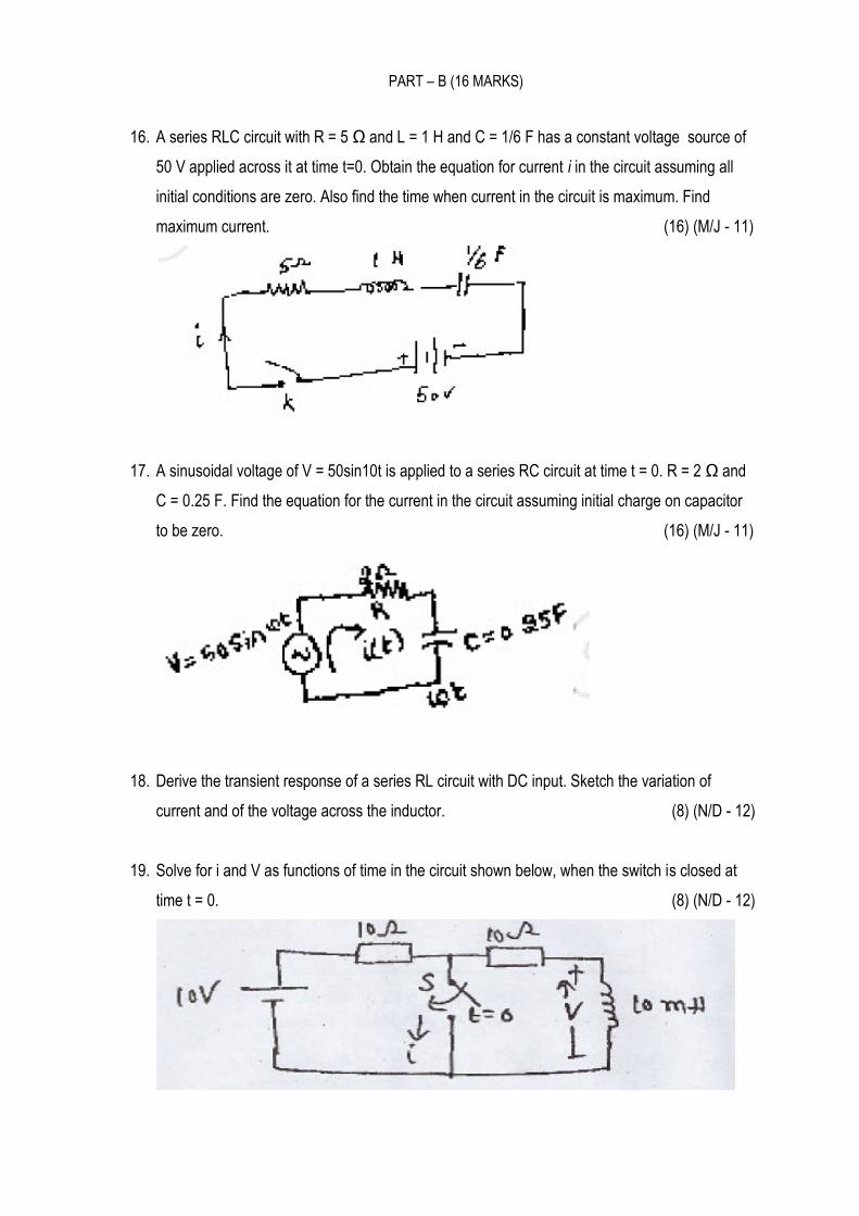
16. A series RLC circuit with R = 5 Ω and L = 1 H and C = 1/6 F has a constant voltage source of
50 V applied across it at time t=0. Obtain the equation for current i in the circuit assuming all
initial conditions are zero. Also find the time when current in the circuit is maximum. Find
maximum current. (16) (M/J - 11)
17. A sinusoidal voltage of V = 50sin10t is applied to a series RC circuit at time t = 0. R = 2 Ω and
C = 0.25 F. Find the equation for the current in the circuit assuming initial charge on capacitor
to be zero. (16) (M/J - 11)
18. Derive the transient response of a series RL circuit with DC input. Sketch the variation of
current and of the voltage across the inductor. (8) (N/D - 12)
19. Solve for i and V as functions of time in the circuit shown below, when the switch is closed at
time t = 0. (8) (N/D - 12)
20. Derive the expression for the complete solution of the current response of RC series circuit with
an excitation of Vcos(ωt+ф). Briefly explain the significance of phase angle in the solution.
(16) (N/D - 12)
21. A series circuit consist of RC in series with switch and supply voltage E. The capacitor has
initial charge E0 . Find the transient voltage Vc(t) when the switch is closed at t = 0.
(16) (M/J - 09)
22. A sinusoidal voltage of frequency of 25 Hz is connected in series with switch and R = 10 Ω and
L = 0.1 H. Calculate the transient current i(t). (16) (M/J - 09)
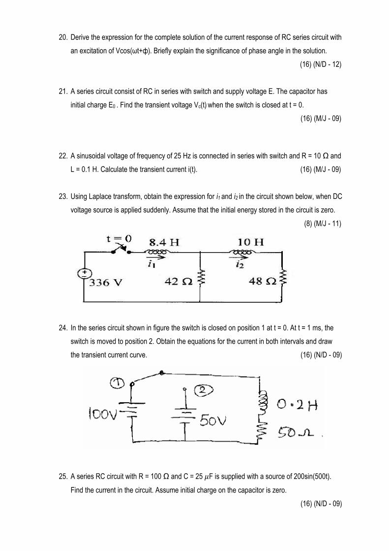
23. Using Laplace transform, obtain the expression for i1 and i2 in the circuit shown below, when DC
voltage source is applied suddenly. Assume that the initial energy stored in the circuit is zero.
(8) (M/J - 11)
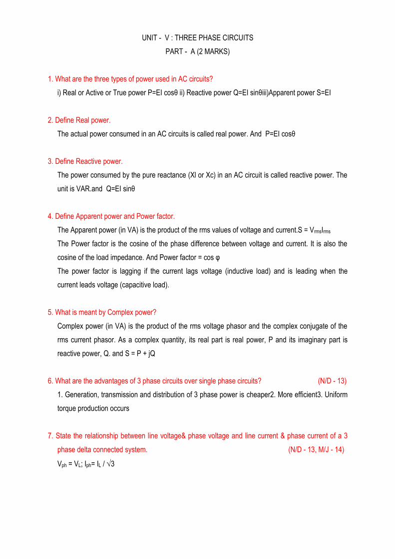
24. In the series circuit shown in figure the switch is closed on position 1 at t = 0. At t = 1 ms, the
switch is moved to position 2. Obtain the equations for the current in both intervals and draw
the transient current curve. (16) (N/D - 09)
25. A series RC circuit with R = 100 Ω and C = 25 F is supplied with a source of 200sin(500t).
Find the current in the circuit. Assume initial charge on the capacitor is zero.
(16) (N/D - 09)
UNIT - V : THREE PHASE CIRCUITS
PART - A (2 MARKS)
1. What are the three types of power used in AC circuits?
i) Real or Active or True power P=EI cosθ ii) Reactive power Q=EI sinθiii)Apparent power S=EI
2. Define Real power.
The actual power consumed in an AC circuits is called real power. And P=EI cosθ
3. Define Reactive power.
The power consumed by the pure reactance (Xl or Xc) in an AC circuit is called reactive power. The
unit is VAR.and Q=EI sinθ
4. Define Apparent power and Power factor.
The Apparent power (in VA) is the product of the rms values of voltage and current.S = VrmsIrms
The Power factor is the cosine of the phase difference between voltage and current. It is also the
cosine of the load impedance. And Power factor = cos φ
The power factor is lagging if the current lags voltage (inductive load) and is leading when the
current leads voltage (capacitive load).
5. What is meant by Complex power?
Complex power (in VA) is the product of the rms voltage phasor and the complex conjugate of the
rms current phasor. As a complex quantity, its real part is real power, P and its imaginary part is
reactive power, Q. and S = P + jQ
6. What are the advantages of 3 phase circuits over single phase circuits? (N/D - 13)
1. Generation, transmission and distribution of 3 phase power is cheaper2. More efficient3. Uniform
torque production occurs
7. State the relationship between line voltage& phase voltage and line current & phase current of a 3
phase delta connected system. (N/D - 13, M/J - 14)
Vph = VL; Iph= IL / 3
8. State the relationship between line voltage & phase voltageand line current &phase current
of a 3 phase star connected system. (N/D - 13)
Vph= VL / 3; Iph= IL
9. Write the expression for the instantaneous values of EMFs in a 3 phase circuit.
VR = Vm sin t; VY = Vm sin ( t-1200); VB = Vm sin ( t-2400)
10. Write the relation between the line and phase value of voltage and current in a balanced
delta connected system?
V √ .
where, V =Line voltage and current V =Phase voltage and current
11. A star connected balanced load draw a current of 35A per phase when connected to a 440 V
supply. Determine the apparent power.
Apparent power=√ =√ *440*35 =26.67KVA
12.Give some method available for measuring three-phase power.
1. Single wattmeter method. 2. Two-wattmeter method. 3. Three-wattmeter method.
13. A star connected load has 6+j8 ohm impedance per phase. Determine the line current if it is
connected to 400V, three phase, and 50Hz supply. (M/J - 12)
Ans: Zph=10Ω/ph, Iph= 23.094A=IL.
14.Define power factor.
Power factor is defined as the cosine of angle between voltage and current. If φ is the angle
between voltage and current then cos φ is called as the power factor.
15. What are the advantages of two-wattmeter method?
The principal advantages is that the algebraic sum of the readings of the two wattmeters indicates
the total power regardless of,(i) Load impedance; (ii)Source impedance; (iii)Difference in
wattmeters; (iv) Phase sequence
16. Two wattmeters are used to measure the total power in a three phase, three wire balanced load.
One wattmeter reads zero. What is the power factor of the load?
The power factor of the load is 0.5
17.Write the expression for the power measured by two watt meters used in 3- phase balanced load, in
terms of voltage, current and power factor. (M/J - 12)
W1 = VLILcos(30 + ); W2 = VLILcos(30 - )
18. Write the expression for power factor in two wattmeter method of power measurement.
( √ )
19. What are the disadvantages of two-wattmeter method?
i) Not applicable for three phase, 4 wire system.ii) the signs of w1 and w2 must be identified and noted
down correctly otherwise it may lead to the wrong results
20. Define Symmetrical System.
It is possible in polyphase system that magnitudes of different alternating voltage are different. But a
three phase system in which the three voltages are of same magnitude and frequency and
displaced from each other by 120° phase angle is defined as symmetrical system.
21. Explain the concept of balanced load.
The load is said to be balanced when magnitudes of all impedances Zph1, Zph2 and Zph3 are equal
and the phase angles of all of them are equal and of same nature either all inductive or all capacitive
or all resistive.
22. What are the advantages of 3Φ system?
1. Constant power 2. Higher rating 3. Power transmission economics
23. What is phase sequence of a 3-phase system? (M/J - 13)
The order in which the voltage in the three phases reach their maximum positive values is called the
phase sequence.
24. Define Phasor and Phase angle.
A sinusoidal wave form can be represented or in terms of a Phasor. A Phasor is a vector with
definite magnitude and direction. From the Phasor the sinusoidal wave form can be reconstructed.
Phase angle is the angular measurement that specifies the position of the alternating quantity
relative to a reference.
25. While measuring power in a circuit by two wattmeter method, under what condition the two
wattmeter reading will be equal and why?
When the power factor is unity or when the load is purely resistive, then the two wattmeterreading
will be equal.
26. Which type of connection of 3Φ system is preferred at the point of utilization? Why?
Three phase, 4 wire systems are used in utilization system so that either single phase or three
phase load can be connected.
27. A delta connected load has (30-j40) ohm impedance per phase. Determine the phase current
if it is connected to 415V, three phase, and 50Hz supply. (M/J - 13)
Phase current, I =
√ = 8 A
28. Write the effect of power factor in energy consumption billing.
Customers are supplied with power having a power factor near to unity around 0.95. Usage of highly
inductive loads by the customers will reduce the power factor. This results in increase transmission
losses so the power suppliers impose power factor penalty for customers using highly inductively
load.
PART – B (16 MARKS)
1. A symmetrical three phase, three wire, 440v supply to a star connected load. The impedance in each
branch are ZR=2+j3Ω, ZY=1-j2Ω and ZB=3+j4Ω. Find its equivalent delta connected load. (8) (M/J – 14)
2. A three phase, balanced delta connected load of 4+j8Ω is connected across a 400V, 3 balanced
supply. Determine the phase currents and line currents. (8) (M/J – 14)
3. A balanced star connected load having an impedance 15+j20Ω per phase is connected to 3 , 440V,
50Hz. Find the line current and power absorbed by the load. (8) (M/J – 14)
4. A symmetrical three phase, three wire 400V, supply is connected to a delta-connected load.
Impedances in each branch are ZRY=10 300Ω, ZYB=10 450Ωand ZBR=2.5 00Ω. Find its equivalent
star-connected load. (8) (M/J – 14)
5. A symmetrical three phase, three wire, 100V supply feeds an unbalanced star connected load.
Impedances in each branch are ZRY=5 00Ω, ZYB=2 900Ωand ZBR=4 0Ω. Find the line currents,
voltage across the impedance and draw the phasor diagram. Also calculate the power consumed by the
load. (16) (M/J – 14)
6. The two wattmeter method is used to measure power in a 3-phase delta connected load. The delta
connected load consists of ZRY=(10+j10)Ω, ZYB=(15-j15)Ω, ZBR=(20+j10)Ω three – phase supply
of phase sequence RYB. Calculate the readings of wattmeter with current coil in line R and B.
(16) (M/J – 14)
7. What are the advantages of three-phase system? (4) (M/J – 13)
8. The two wattmeter method produces wattmeter readings P1=1560W and P2=2100 W when connected
to a delta connected load. If the line voltage is 220V, calculate: (1) the per-phase average power (2) the
per-phase reactive power (3) the power factor and (4) the phase impedance. (12) (M/J – 13)
9. Prove that the total instantaneous power in a balanced three-phase system is constant and is equal to
the average power whether the load is star or delta connected. (10) (M/J – 13)
10. An unbalanced star-connected load has balanced voltages of 100v and RBY sequence. Calculate the
line currents and the neutral current.
Take: ZA=15Ω, ZB=(10+j5)Ω and ZB=(6-j8)Ω. (6) (M/J – 13)
11. A balanced Δ-connected load has one phase current IBC = 2 90 A. Find the other phase currents and
the three line currents if the system is an ABC system. If the line voltage is 100 V, what is the load
impedance? (8) (M/J – 11)
12. The power consumed in a three phase balanced star connected load is 2 kW at a power factor of 0.8
lagging. The supply voltage is 400 V, 50 Hz. Calculate the resistance and reactance of each phase.
(8) (M/J – 11)
13. Show that two wattmeters are sufficient to measure power in a balanced or unbalanced three-phase
load connected to a balanced supply. (10) (M/J – 11)
14. A three phase, 220 V, 50 Hz, 11.2 kW induction motor has a full load efficiency of 88% and draws a line
current of 38 A under full load, when connected to three phase, 220 V supply. Find the reading on two
wattmeters connected in the circuit to measure the input to the motor. Determine also the power factor
at which the motor is operating. (6) (M/J – 11)
15. A 3 phase, 3 wire 120 V RYB system feeds a ∆-connected load whose phase impedance is 30 450.
Find the phase and line currents in this system and draw the phasor diagram. (8) (N/D – 12)
16. A three-phase four wire 120 V ABC system feeds an unbalanced Y-connected load with ZA=5 0Ω,
ZB=10 0Ω and ZC=20 600Ω. Obtain the four line currents. (8) (N/D – 12)
17. Three impedances Z1= (17.32+j10), Z2= (20+j34.34) and Z3= (0-j10) ohms are delta connected to a 400
V, three phase system. Determine the phase currents, line currents and total power consumed by the
load. (8) (N/D – 12)
18. Two wattmeters are connected to measure the power in a 3 , 3wire balanced load. Determine the total
power and power factor if the two wattmeters read
(1) 1000 w each, both positive
(2) 1000 w, each, of opposite sign. (8) (M/J – 10)
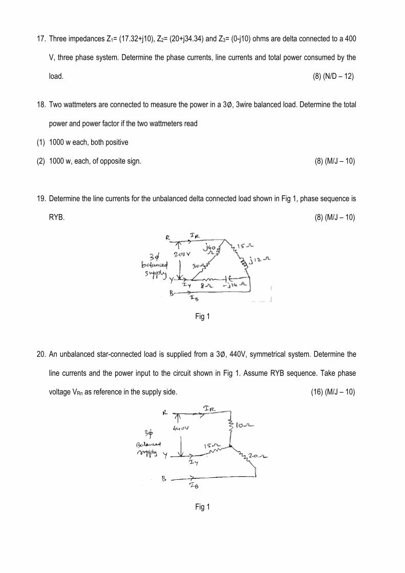
19. Determine the line currents for the unbalanced delta connected load shown in Fig 1, phase sequence is
RYB. (8) (M/J – 10)
Fig 1
20. An unbalanced star-connected load is supplied from a 3 , 440V, symmetrical system. Determine the
line currents and the power input to the circuit shown in Fig 1. Assume RYB sequence. Take phase
voltage VRn as reference in the supply side. (16) (M/J – 10)
Fig 1
21. Derive the expression for the total power in a 3 phase balanced circuit using two wattmeters.
(10) (N/D – 09)
22. The power input to a 2000 V, 50 Hz, 3 – phase motor is measured by two wattmeters which indicate
300 kW and 100 kW respectively. Calculate the input power, power factor and the line current.
(6) (N/D – 09)
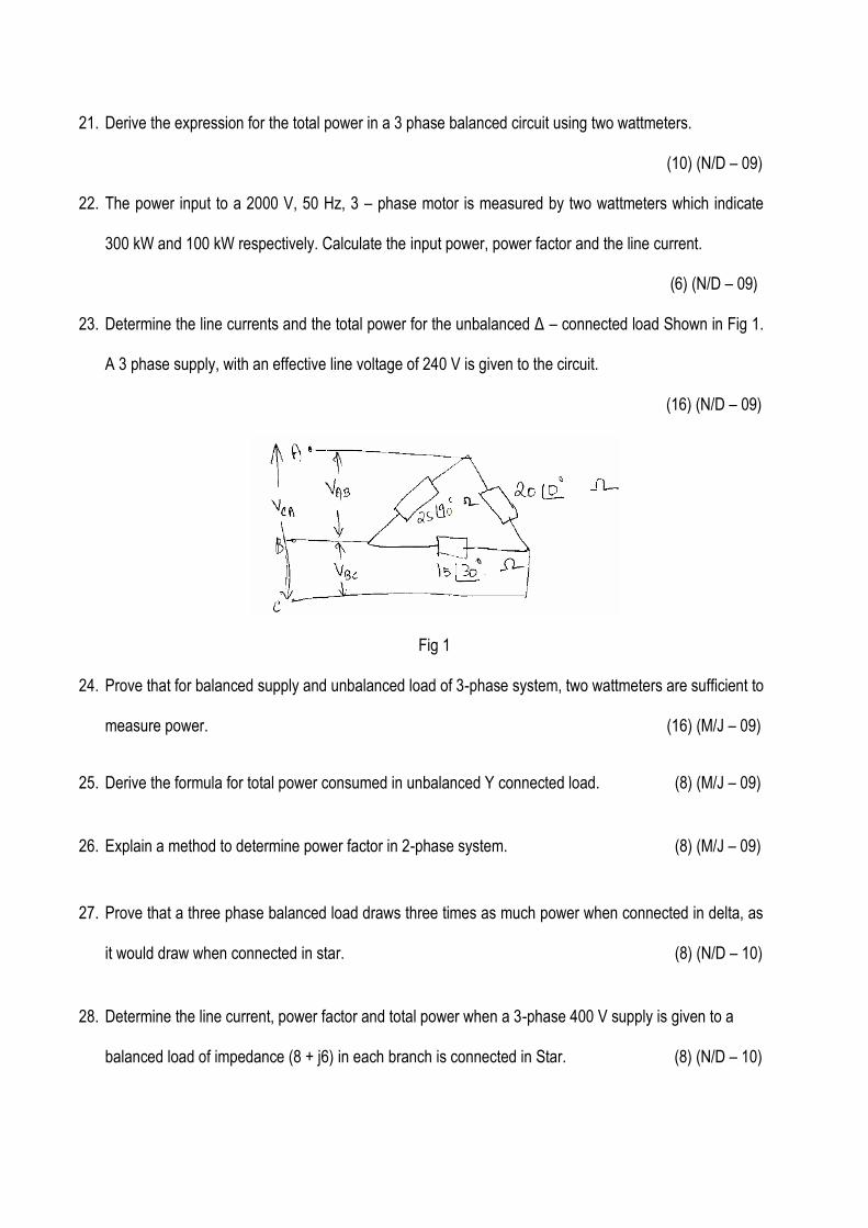
23. Determine the line currents and the total power for the unbalanced Δ – connected load Shown in Fig 1.
A 3 phase supply, with an effective line voltage of 240 V is given to the circuit.
(16) (N/D – 09)
Fig 1
24. Prove that for balanced supply and unbalanced load of 3-phase system, two wattmeters are sufficient to
measure power. (16) (M/J – 09)
25. Derive the formula for total power consumed in unbalanced Y connected load. (8) (M/J – 09)
26. Explain a method to determine power factor in 2-phase system. (8) (M/J – 09)
27. Prove that a three phase balanced load draws three times as much power when connected in delta, as
it would draw when connected in star. (8) (N/D – 10)
28. Determine the line current, power factor and total power when a 3-phase 400 V supply is given to a
balanced load of impedance (8 + j6) in each branch is connected in Star. (8) (N/D – 10)
29. A three-phase four-wire 120 V ABC system feeds an unbalanced Y-connected load with ZA = 5 00 , ZB
= 10 300, and ZC = 20 600 . Obtain the four line currents. (8) (N/D – 10)
30. Three impedances Z1 = (17.32+j10), Z2 = (20+j34.64) and Z3 = (0 – j10) ohms are delta connected to a
400 V, three phase system. Determine the phase currents, line currents and total power consumed by
the load. (8) (N/D – 10)