Embed Size (px)
Citation preview

EE 435
Lecture 14
Two-Stage Op Amp Design

Two-stage Cascade (continued)
2
0TOT1
1,2 kkβ4Ajk-2
pp
~
The pole spread for maximal frequency domain flatness or fast non-ringing time
domain response is quite large for the two-stage amplifier but can be achieved
Usually will make angle of feedback poles with imaginary axis between 45o and
90o
This results (for all-pole cascade) in an open loop pole spread that satisfies the
relationship0TOT0TOT A2βkA4β
“Compensation” is the modification of the pole locations of an amplifier to
achieve a desired closed-loop pole angle
0A pA
s p
Review from Last Time

Cascaded Amplifier Issues
Four or more amplifier cascades - problems even larger than for three stages
-- seldom used in industry but starting to appear !
-- seldom used in industry !
Two amplifier cascades 0TOT0TOT A2βkA4β
-- widely used in industry but compensation is essential !
Three amplifier cascades - for ideally identical stages 3
0βA8
Single-stage amplifiers
-- widely used in industry, little or no concern about compensation
Note: Some amplifiers that are termed single-stage amplifiers in many books and papers are
actually two-stage amplifiers and some require modest compensation. Some that are termed two-
stage amplifiers are actually three-stage amplifiers. These invariable have a very small gain on the
first stage and a very large bandwidth. The nomenclature on this summary refers to the number of
stages that have reasonably large gain. Results given above vary somewhat if a zero is present in
the amplifier.
0A pA
s p
Review from Last Time

Summary of Cascaded Amplifier Characteristics
A cascade of amplifiers can result in a very high dc gain !
Characteristics of feedback amplifier (where the op amp is applied) are of
ultimate concern
Some critical and fundamental issues came up with even the most basic
cascades when they are used in a feedback configuration
Must understand how open-loop and closed-loop amplifier performance
relate before proceeding to design amplifiers by cascading
Review from Last Time

Summary of Amplifier Characteristics
An amplifier is stable iff all poles lie in the open LHP
Routh-Hurwitz Criteria is often a practical way to determine if an amplifier
is stable
Although stability of an amplifier is critical, a good amplifier must not only
be stable but generally must satisfy magnitude peaking and/or settling
requirements thus poles need to be moved a reasonable distance from the
imaginary axis
The cascade of three identical high-gain amplifiers will result in a pole-pair
far in the right half plane when feedback is applied so FB amplifier will be
unstable
3
0
3
3
0FB
βA1p
s
A
Aβ1
AA
~
3
0βA8
For stability
0A pA
s p
Review from Last Time

• Fundamental Amplifier Design Issues
• Single-Stage Low Gain Op Amps
• Single-Stage High Gain Op Amps
• Two-Stage Op Amp– Compensation
– Breaking the Loop
• Other Basic Gain Enhancement Approaches
• Other Issues in Amplifier Design
• Summary Remarks
Amplifier Design

Two-stage op amp design
It is essential to know where the poles of the op
amp are located since there are some rather strict
requirements about the relative location of the open-
loop poles when the op amp is used in a feedback
configuration.

Poles and Zeros of AmplifiersVDD
M1 M2
VB2
M3 M4
VINVIN
M5
VDD
M6M7
VB2
M8 M9
CL
M10
VOUT
C1
C2
C3 C4
C5
C6
C7 C8
• There are a large number of parasitic capacitors in an amplifier(appprox 5 for each transistor)
• Many will appear in parallel but the number of equivalent capacitors can still be large
• Order of transfer function is equal to the number of non-degenerate energy storage
elements
• Obtaining the transfer function of a high-order network is a lot of work !
• Essentially every node in an amplifier has a capacitor to ground and these often
dominate the frequency response of the amplifier (but not always)
Cascaded Amplifier showing some of the capacitors

Pole approximation methods1. Consider all shunt capacitors
2. Decompose these into two sets, those that create low frequency poles
and those that create high frequency poles (large capacitors create low
frequency poles and small capacitors create high frequency poles)
{CL1, … CLk} and {CH1, … CHm}
3. To find the k low frequency poles, replace all independent voltage sources with
ss shorts and all independent current sources with ss opens, all high-frequency
capacitors with ss open circuits and, one at a time, select CLh and determine
the impedance facing it, say RLh if all other low-frequency capacitors are replaced
with ss open circuits. Then an approximation for the pole corresponding to
CLh is
pLh=-1/(RLhCLh)
4. To find the m high-frequency poles, replace all independent voltage sources with
ss shorts and all independent current sources with ss opens, replace all low-frequency
capacitors with ss short circuits and, one at a time, select CHh and determine the
impedance facing it, say RHh if all other high-frequency capacitors are replaced with ss
open circuits. Then the approximation for the pole corresponding to CHh is
pHh=-1/(RHhCHh)

Pole approximation methods
These are just pole approximations but are often quite good
Provides closed-form analytical expressions for poles in terms of
components of the network that can be managed during design
Provides considerable insight into what is affecting the frequency response
of the amplifier
Pole approximation methods give no information about zero locations
Many authors refer to the “pole on a node” and this notation comes from
the pole approximation method discussed on previous slide

Example: Obtain the approximations to the
poles of the following circuit
R1=1K R2=5K
C1=100pF C2=200pF
VIN
VOUT
Since C1 and C2 and small, have two high-frequency poles
{C1, C2}

R1=1K R2=5K
C2=200pF
R1=1K R2=5K
C1=100pF C2=200pF
VIN
VOUT
R1=1K R2=5K
C1=100pF
H22 1 2
1p = -
C R +R
H11 1
1p = -
C R
H2p = - 833Krad/sec
H1p = -10M rad/sec

R1=1K R2=5K
C1=100pF C2=200pF
VIN
VOUT
H2p = - 821Krad/sec
H1p = -12.2M rad/sec
In this case, an exact solution is possible
1 2 1 2
2
1 1 2 2 2 1 1 2 1 2
1
R R C C
1 1 1 1s + + + s+
R C R C R C R R C C
T s
(1.4% error)
(18% error)

Basic Two-Stage Cascade
F1
P1
VIN
F2
P2
VOUT
• Simple Concept
• Must decide what to use for the two quarter circuits
Can be extended to fully differential on first or second stage

Compensation of Basic Two-Stage Cascade
F1
P1
VIN
F2
P2
VOUT
C1
• Modest variants of the compensation principle are often used
• Internally compensated creates the dominant pole on the internal node
• Output compensated created the dominant pole on the external node
• Output compensated often termed “self-compensated”
F1
P1
VIN
F2
P2
VOUT
C2
Internally Compensated Output Compensated
Everything else is just details !!

Two-stage Architectural Choices
Common
SourceCascode
Regulated
Cascode
Folded
Cascode
Folded
Regulated
Cascode
Current
Mirror
Differential
Input
Single
Ended Input
Tail Voltage Tail CurrentStage 1
Output Compensated Internally Compensated
Common
SourceCascode
Regulated
Cascode
Folded
Cascode
Folded
Regulated
Cascode
Current
Mirror
Differential
Input
Single
Ended Input
Tail Voltage Tail CurrentStage 2

Two-stage Architectural Choices
Output Compensated Internally Compensated
6
2
2
6
2
2
2
Plus n-channel or p-channel on each stage 4
2304 Choices !!!
Common
SourceCascode
Regulated
Cascode
Folded
Cascode
Folded
Regulated
Cascode
Current
Mirror
Common
SourceCascode
Regulated
Cascode
Folded
Cascode
Folded
Regulated
Cascode
Current
Mirror
Differential
Input
Differential
Input
Single
Ended Input
Single
Ended Input
Tail Voltage Tail CurrentTail Voltage Tail CurrentStage 1
Common
SourceCascode
Regulated
Cascode
Folded
Cascode
Folded
Regulated
Cascode
Current
Mirror
Common
SourceCascode
Regulated
Cascode
Folded
Cascode
Folded
Regulated
Cascode
Current
Mirror
Differential
Input
Differential
Input
Single
Ended Input
Single
Ended Input
Tail Voltage Tail CurrentTail Voltage Tail CurrentStage 2

Two-stage Architectural Choices
Which of these 2304 choices can be used to build a good op amp?
All of them !!
Output Compensated Internally Compensated
Plus n-channel or p-channel on each stage
Common
SourceCascode
Regulated
Cascode
Folded
Cascode
Folded
Regulated
Cascode
Current
Mirror
Common
SourceCascode
Regulated
Cascode
Folded
Cascode
Folded
Regulated
Cascode
Current
Mirror
Differential
Input
Differential
Input
Single
Ended Input
Single
Ended Input
Tail Voltage Tail CurrentTail Voltage Tail CurrentStage 1
Common
SourceCascode
Regulated
Cascode
Folded
Cascode
Folded
Regulated
Cascode
Current
Mirror
Common
SourceCascode
Regulated
Cascode
Folded
Cascode
Folded
Regulated
Cascode
Current
Mirror
Differential
Input
Differential
Input
Single
Ended Input
Single
Ended Input
Tail Voltage Tail CurrentTail Voltage Tail CurrentStage 2

Two-stage Architectural Choices
There are actually a few additional variants so the number
of choices is larger
Basic analysis of all is about the same and can be
obtained from the quarter circuit of each stage
A very small number of these are actually used
Some rules can be established that provide guidance as
to which structure may be most useful in a given
application
Two-stage Architectural Choices
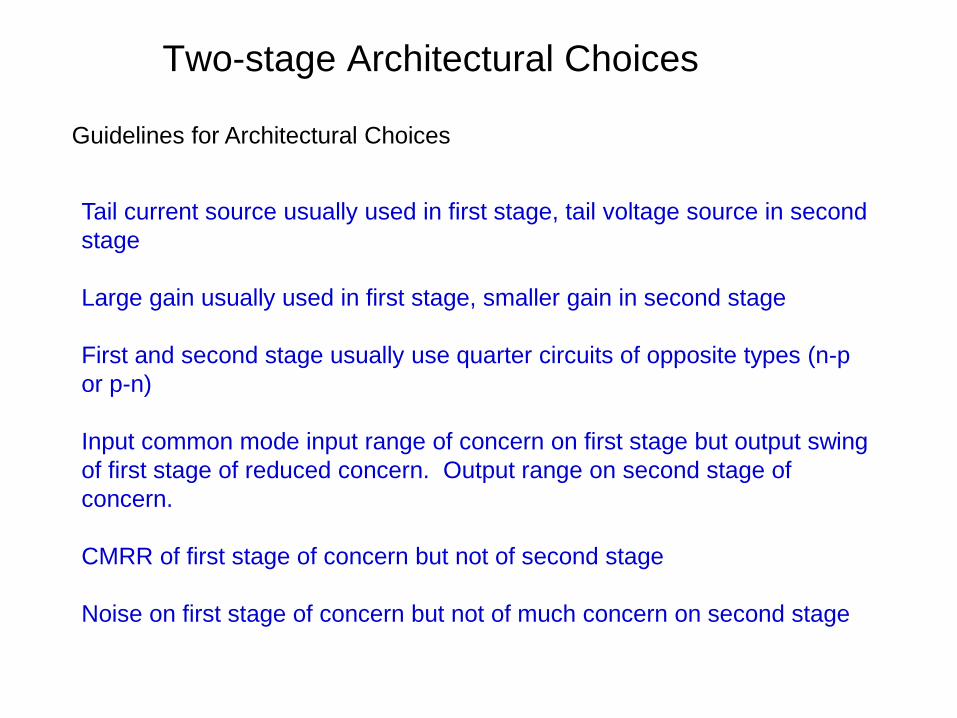
Guidelines for Architectural Choices
Tail current source usually used in first stage, tail voltage source in second
stage
Large gain usually used in first stage, smaller gain in second stage
First and second stage usually use quarter circuits of opposite types (n-p
or p-n)
Input common mode input range of concern on first stage but output swing
of first stage of reduced concern. Output range on second stage of
concern.
CMRR of first stage of concern but not of second stage
Noise on first stage of concern but not of much concern on second stage

Two-stage Architectural Choices
Output Compensated Internally Compensated
Plus n-channel or p-channel on each stage
Common
SourceCascode
Regulated
Cascode
Folded
Cascode
Folded
Regulated
Cascode
Current
Mirror
Common
SourceCascode
Regulated
Cascode
Folded
Cascode
Folded
Regulated
Cascode
Current
Mirror
Differential
Input
Differential
Input
Single
Ended Input
Single
Ended Input
Tail Voltage Tail CurrentTail Voltage Tail CurrentStage 1
Common
SourceCascode
Regulated
Cascode
Folded
Cascode
Folded
Regulated
Cascode
Current
Mirror
Common
SourceCascode
Regulated
Cascode
Folded
Cascode
Folded
Regulated
Cascode
Current
Mirror
Differential
Input
Differential
Input
Single
Ended Input
Single
Ended Input
Tail Voltage Tail CurrentTail Voltage Tail CurrentStage 2
Basic Two-Stage Op Amp

Two-stage Architectural Choices
Output Compensated Internally Compensated
Plus n-channel or p-channel on each stage
Common
SourceCascode
Regulated
Cascode
Folded
Cascode
Folded
Regulated
Cascode
Current
Mirror
Common
SourceCascode
Regulated
Cascode
Folded
Cascode
Folded
Regulated
Cascode
Current
Mirror
Differential
Input
Differential
Input
Single
Ended Input
Single
Ended Input
Tail Voltage Tail CurrentTail Voltage Tail CurrentStage 1
Common
SourceCascode
Regulated
Cascode
Folded
Cascode
Folded
Regulated
Cascode
Current
Mirror
Common
SourceCascode
Regulated
Cascode
Folded
Cascode
Folded
Regulated
Cascode
Current
Mirror
Differential
Input
Differential
Input
Single
Ended Input
Single
Ended Input
Tail Voltage Tail CurrentTail Voltage Tail CurrentStage 2
Cascode-Cascade Two-Stage Op Amp

Two-stage Architectural Choices
Output Compensated Internally Compensated
Plus n-channel or p-channel on each stage
Common
SourceCascode
Regulated
Cascode
Folded
Cascode
Folded
Regulated
Cascode
Current
Mirror
Common
SourceCascode
Regulated
Cascode
Folded
Cascode
Folded
Regulated
Cascode
Current
Mirror
Differential
Input
Differential
Input
Single
Ended Input
Single
Ended Input
Tail Voltage Tail CurrentTail Voltage Tail CurrentStage 1
Common
SourceCascode
Regulated
Cascode
Folded
Cascode
Folded
Regulated
Cascode
Current
Mirror
Common
SourceCascode
Regulated
Cascode
Folded
Cascode
Folded
Regulated
Cascode
Current
Mirror
Differential
Input
Differential
Input
Single
Ended Input
Single
Ended Input
Tail Voltage Tail CurrentTail Voltage Tail CurrentStage 2
Folded Cascode-Cascade Two-Stage Op Amp

Basic Two-Stage Op AmpV
DD
VSS
M1
M2
M3 M
4M
5
CL
VIN
VOUT
M6M
7
IT
VB2
VB3
VIN
CC
o One of the most widely used op amp architectures
o Essentially just a cascade of two common-source stages
o Compensation Capacitor CC used to get wide pole separation
o Two poles in amplifier
o No universally accepted strategy for designing this seemingly
simple amplifier
Pole spread makes CC unacceptably large0 20 1 Aβ A

End of Lecture 14