Embed Size (px)
Citation preview
www.kbp.co.uk
SpecificationGuide
Edition 10
Wide range of white, coloured andfoiled woodgrain PVC-UE rooflineboards, window trims andcladding planks.
Offering a complete solution©
Fascias | Soffits | Cladding | Windowboards | Architraves
p/2
3 Benefits of Kestrel PVC-UE & PVC-U
4 The Kestrel Range and Colours
5 Fascia Installation Details
6 Fascia Installation Details
7 Fascia Installation Details
8 Bargeboard Installation Details
9 Soffit Installation Details
10 Roofline Range & Dimensions
11 Roofline Range & Dimensions
12 Boxed End Installation Details
13 Roofline Ventilation & Provision of Ventilation
14 Roofline Ventilation
15 Soffit Range
16 Typical Jointing Details
17 Typical Jointing Details
18 Working with Woodgrain Products: Roofline
19 Fixing Summary - Roofline
20 White Cladding Installations
21 White Cladding Installations
22 White Cladding Installations
23 White Cladding Installations
24 White Cladding Installations
25 White Cladding Installations
26 Working with Woodgrain Products: Cladding
27 Fixing Summary - Cladding
28 Kavex Textured Cladding Installations
29 Kavex Textured Cladding Installations
30 Kavex Textured Cladding Installations
31 Fixing Summary - Kavex Cladding
32 Internal Applications for Kestrel Products
33 Windowboards & Trims
34 Window Board Range
35 Trims Range
36 10 Most Frequently Asked Questions
37 Product Characteristics
38 Product Characteristics
39 Fixing Summary - General
Cla
dd
ing
Win
dow
boar
ds&
Tri
ms
Tech
nic
alR
oo
flin
e
Contents
p/3
Benefits of Kestrel PVC-UE & PVC-U
Kestrel’s popularity in the new build, specification,architectural and refurbishment sector stems from itsproduct reliability and wide acceptance amongst thetrade and the general public.
Refurbishment programmes by housing associationsand local authorities acknowledge Kestrel products asthe route to lower maintenance costs.
Key FeaturesFlexibility A wide range of designs and styles to suit virtuallyevery commercial, industrial and domestic application.With flexibility of application built in at every stage.
Durability Long-lasting, reliable products that will not rot, split,warp or crack and that are designed to resist theelements.
Practicality Never needs painting or preserving and will staylooking good for years to come. Easy to specify andsimple to install.
Good-looking A wide variety of colours and finishes to choose fromwith designs for every application.
Quality - ISO 9001The company has a Quality Management Systemapproved by the British Standards Institute to ISO 9001(FM 605711).
Environmental - ISO 14001The company has a Environmental Management Systemapproved by the British Standards Institute to ISO14001 (EMS 605712).
Responsible Sourcing - BS EN ISO 6001The company has a Responsible Sourcing Systemapproved by the British Standards Institute to ISO 6001(BES 605713).
RecovinylRecovinyl facilitates the collection and recycling of PVCpost-consumer waste from the construction anddemolition sector.
Product GuaranteesKestrel’s white products are guaranteed for 20 years asstandard or can be extended to 35 years through ourRegistered Installer Scheme. All foiled profiles areguaranteed for 10 years provided that approvedinstallation and maintenance instructions are followed.Copies of the guarantees which relate to white andfoiled products are available from customer services on 08702 406107.
Vinyl Plus Eliminating the lead content in PVC has been a matterof particular concern for responsible manufacturers inour industry. As recommended by the EuropeanCommission, UK Government and the PVC industry’sVinyl Plus initiative, some suppliers have already madethe switch. Kestrel is among those leading the way. Infact, we believe we were the first in the UK to offercalcium organic core and calcium organic skin in ourPVC-UE. As well as future proofing the product for ourcustomers in case new legislation on material usagedoes come into play, we are also doing what we cannow in the global drive for environmental protection.
Fastrack CadFastrack CAD is an online CAD database which givesarchitects and specifiers the opportunity to downloadDXF or DWG files. Kestrel's library of CAD drawingswhich is available on-line and can be accessed anddownloaded by visiting www.kbp.co.uk
NBSThe National Building Specification (NBS) is a library ofclauses that can be selected and edited and used toproduce project specifications. Kestrel's NBSinformation is available on-line and can be accessedthrough www.thenbs.com
CE MarkingKestrel PVC-UE cladding is covered by a harmonisedEuropean standard - BS EN 13245:2008. A declarationof performance to this standard is available and theproduct packaging caries a 'CE marking' label.
BES 605713
REGISTERED RECYCLER
EMS 605712
FM 605711
COLOURED STR
UC
TUR
AL G
UARANTEECOLOUR G
UAR
AN
TEE
p/4
The Kestrel Range and Colours
Fascia and Capping boardsKestrel’s extensive range of Square Leg, Flush,Ogee and Bullnosed fascia boards provide thecomplete solution to every roofline application.Available in three whites and a selection of foiledcolours
Soffit/General purpose boards & accessoriesAvailable in widths from 100mm to 600mm, in 5mlengths, three whites and wide range of foiledcolours. Now also available with two finishededges.
Preventilated Soffit Available in Kestrel whites and woodgrain, the pre-ventilated soffit boards incorporate integral airslots giving 10mm or 25mm continuous ventilation.Boards are 9mm thick and are available in widthsup to 600mm.
Kavex Textured CladdingKestrel’s textured claddings are available in twostyles: Shiplap with 150mm or 300mm coverageand Featheredge with 270mm coverage, bothcome with a full range of accessories. They areavailable in White, Sand, Cream, Light Blue andLight Grey providing an effective yet stylishexternal cladding solution.
Ventilation and Eaves protection SystemsAn over fascia system which provides analternative method of roof void ventilation. Simpleto install with easy fit clipping joints, the system isavailable in Black. Circular soffit vents are alsoavailable, in White and all three solid colours.
Window BoardsA variety of shapes, sizes and finishes andavailable to suit all domestic and commercialwindow applications.
Finishing Trims / ArchitravesKestrel’s wide variety of finishing trims /architravesare available in a selection of colours, shapes andsizes to suit all window and internal finishingapplications.
Cladding systemsKestrel’s cladding systems can be fixed vertically,horizontally or diagonally and are available in twostyles: Shiplap with 150mm coverage and V-jointwith 100mm coverage. The system is available inall white and woodgrain colours.
FixingsA selection of sizes is available in a variety ofcolours to suit all applications.
Kestrel PVC-UE & PVC-U extruded products are ideally suited for both domestic and commercial applications. They perform better in use than traditional alternatives, are quick and easy to install, and are virtually maintenance-free.When calculating whole-life costs, Kestrel’s products invariably offer a more practical and lower cost option.
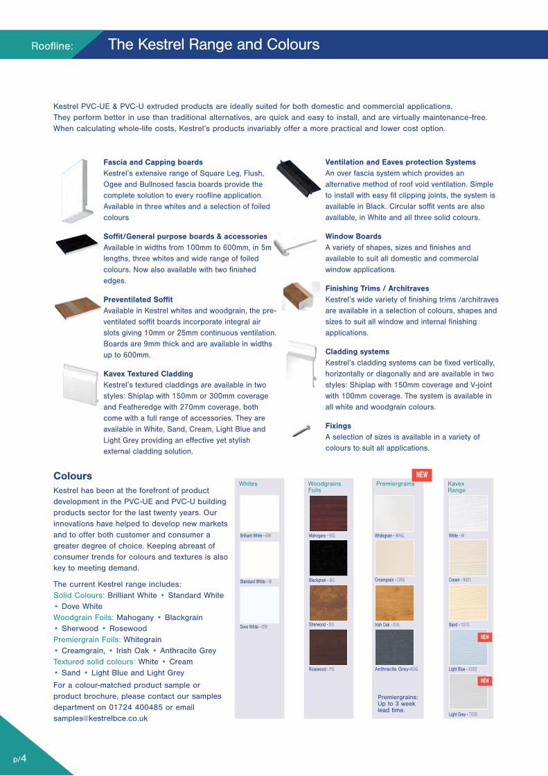
ColoursKestrel has been at the forefront of productdevelopment in the PVC-UE and PVC-U buildingproducts sector for the last twenty years. Ourinnovations have helped to develop new marketsand to offer both customer and consumer agreater degree of choice. Keeping abreast ofconsumer trends for colours and textures is alsokey to meeting demand.
The current Kestrel range includes:Solid Colours: Brilliant White • Standard White• Dove WhiteWoodgrain Foils: Mahogany • Blackgrain • Sherwood • Rosewood Premiergrain Foils: Whitegrain • Creamgrain, • Irish Oak • Anthracite GreyTextured solid colours: White • Cream • Sand • Light Blue and Light Grey
For a colour-matched product sample orproduct brochure, please contact our samplesdepartment on 01724 400485 or [email protected]
Whites
Brilliant White - BW
Standard White - W
Dove White - DW
WoodgrainsFoils
Kavex Range
Blackgrain - BG
Sherwood - SG
Rosewood - PG
Sand - 1015
Cream - 9001
Light Grey - 7035
Whitegrain - WHG
Creamgrain - CRG
White - W
Light Blue - X002Anthracite Grey-AGG
NEW
NEW
NEW
Premiergrains
Premiergrains:Up to 3 weeklead time.
Irish Oak - IOG
Mahogany - WG
Roofline:
p/5
Fascia Installation Details
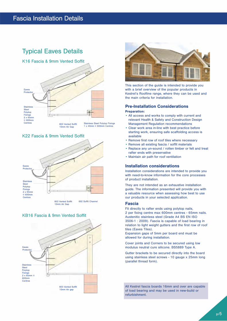
This section of the guide is intended to provide youwith a brief overview of the popular products inKestrel’s Roofline range, where they can be used andthe main criteria for installation.
Pre-Installation ConsiderationsPreparation:• All access and works to comply with current and
relevant Health & Safety and Construction DesignManagement Regulation recommendations
• Clear work area in-line with best practice beforestarting work, ensuring safe scaffolding access isavailable
• Remove first row of roof tiles where necessary• Remove all existing fascia / soffit materials• Replace any un-sound / rotten timber or felt and treat
rafter ends with preservative• Maintain air path for roof ventilation
Installation considerationsInstallation considerations are intended to provide youwith need-to-know information for the core processesof product installation.
They are not intended as an exhaustive installationguide. The information presented will provide you witha valuable resource when assessing how best to useour products in your selected application.
FasciaFit directly to rafter ends using polytop nails, 2 per fixing centre max 600mm centres - 65mm nails.Austenitic stainless steel (Grade A4 BS EN ISO 3506-1 : 2009). Fascia is capable of load bearing inrelation to light weight gutters and the first row of rooftiles (Eaves Tiles).Expansion gaps of 5mm per board end must beallowed for during installation.
Cover joints and Corners to be secured using lowmodulus neutral cure silicone. BS5889 Type A.
Gutter brackets to be secured directly into the boardusing stainless steel screws - 10 gauge x 25mm long(parallel thread form).
All Kestrel fascia boards 16mm and over are capableof load bearing and may be used in new-build orrefurbishment.
EavesProtector
StainlessSteelPolytopFixings2 x 65mm@ 600mmCentres 803 Vented Soffit
10mm Air Gap
Stainless Steel Polytop Fixings1 x 40mm @ 600mm Centres
StainlessSteelPolytopFixings2 x 65mm@ 600mmCentres
803 Vented Soffit10mm Air Gap
692 Soffit Channel
K16 Fascia & 9mm Vented Soffit
Typical Eaves Details
K22 Fascia & 9mm Vented Soffit
KB16 Fascia & 9mn Vented Soffit
EavesProtector
EavesProtector
StainlessSteelPolytopFixings2 x 65mm @600mmCentres
803 Vented Soffit10mm Air gap
Roofline:
p/6
Fascia Installation Details
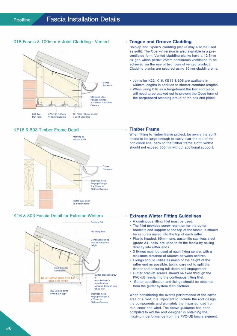
Tongue and Groove CladdingShiplap and Open-V cladding planks may also be usedas soffit. The Open-V version is also available in a pre-ventilated form. Vented cladding planks have a 12.5mmair gap which permit 25mm continuous ventilation to beachieved via the use of two rows of vented product.Cladding planks are secured using 30mm cladding pins.
• Joints for K22, K16, KB16 & 605 are available in600mm lengths in addition to shorter standard lengths.
• When using 018 as a bargeboard the box end piecewill need to be packed out to prevent the Ogee form ofthe bargeboard standing proud of the box end piece.
Timber FrameWhen fitting to timber frame project, be aware the soffitneeds to be large enough to carry over the top of thebrickwork line, back to the timber frame. Soffit widthsshould not exceed 300mm without additional support.
Extreme Winter Fitting Guidelines• A continuous tilting fillet must be used.• The fillet provides screw retention for the gutter
brackets and support to the top of the fascia. It shouldbe securely nailed into the top of each rafter
• Plastic headed, 65mm long, austenitic stainless steel(grade A4) nails, are used to fix the fascia by nailingdirectly into rafter ends.
• 2 fixings must be used at each fixing centre, with amaximum distance of 600mm between centres.
• Fixings should utilise as much of the height of therafter end as possible, taking care not to split thetimber and ensuring full depth nail engagement.
• Gutter bracket screws should be fixed through thePVC-UE fascia into the continuous tilting fillet.
• Gutter specification and fixings should be obtainedfrom the gutter system manufacturer.
When considering the overall performance of the eavesarea of a roof, it is important to include the roof design,the components and ultimately the imparted load fromrain, snow and wind. The above guidance has beencompiled to aid the roof designer in obtaining themaximum performance from the PVC-UE fascia element.
681 TwoPart Trim
Framing tosecure soffit
Soffit over brickto timber frame
Max distanceachievable
803 vented soffit(10mm air gap)
EavesProtector
EavesProtector
Stainless SteelPolytop Fixings2 x 65mm @ 600mmCentres
871/100 100mm VentedV-Joint Cladding
671/100 100mmV-Joint Cladding
Stainless SteelPolytop Fixings2 x 65mm @ 600mm Centres
Sarking Felt
Fix tilting fillet
Continuous tiltingfillet to full fasciaheight
Gutter bracket screwtomanufacturer'sspecificationscrewed through intotilting fillet
Stainless SteelPolytop Fixings 2x 65mm @600mm Centres
Note: Spread nails over fullrafter end height
018 Fascia & 100mm V-Joint Cladding - Vented
KF16 & 803 Timber Frame Detail
K16 & 803 Fascia Detail for Extreme Winters
Stainless Steel Polytop Fixings1 x 40mm @ 600mm Centres
Eaves Protector
Stainless SteelPolytop Fixings2 x 50mm @600mm Centres
803 Vented Soffit10mm Air gap
AIR PATH
K16 Fascia
Secure torafter endswithPolynails 2 x 65mm @600mmCentres
903 range 25mm vented soffit toventilate 50mm air space
Flat Roof Detail
p/7
Fascia Installation Details
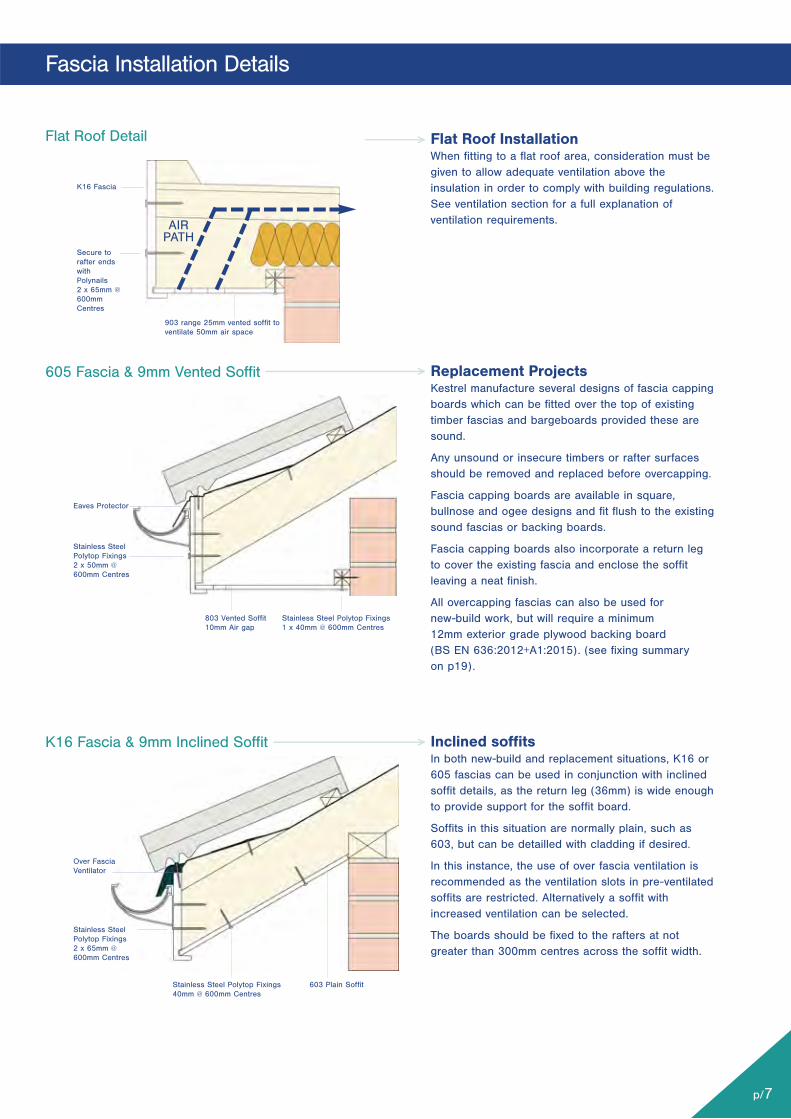
Flat Roof InstallationWhen fitting to a flat roof area, consideration must begiven to allow adequate ventilation above theinsulation in order to comply with building regulations.See ventilation section for a full explanation ofventilation requirements.
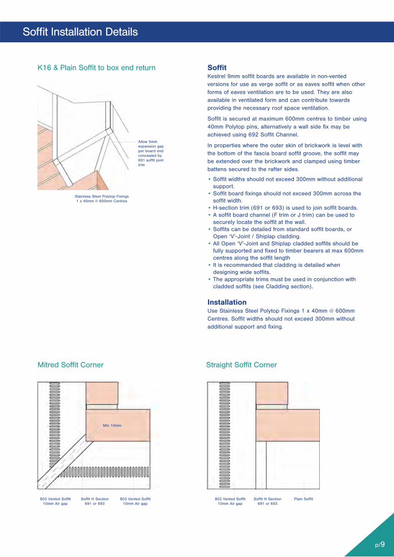
Replacement ProjectsKestrel manufacture several designs of fascia cappingboards which can be fitted over the top of existingtimber fascias and bargeboards provided these aresound.
Any unsound or insecure timbers or rafter surfacesshould be removed and replaced before overcapping.
Fascia capping boards are available in square,bullnose and ogee designs and fit flush to the existingsound fascias or backing boards.
Fascia capping boards also incorporate a return legto cover the existing fascia and enclose the soffitleaving a neat finish.
All overcapping fascias can also be used for new-build work, but will require a minimum 12mm exterior grade plywood backing board (BS EN 636:2012+A1:2015). (see fixing summary on p19).
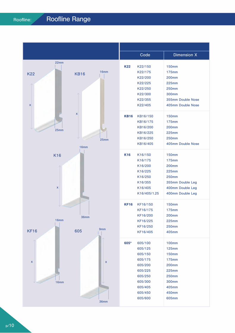
Inclined soffitsIn both new-build and replacement situations, K16 or605 fascias can be used in conjunction with inclinedsoffit details, as the return leg (36mm) is wide enoughto provide support for the soffit board.
Soffits in this situation are normally plain, such as603, but can be detailled with cladding if desired.
In this instance, the use of over fascia ventilation isrecommended as the ventilation slots in pre-ventilatedsoffits are restricted. Alternatively a soffit withincreased ventilation can be selected.
The boards should be fixed to the rafters at notgreater than 300mm centres across the soffit width.
605 Fascia & 9mm Vented Soffit
K16 Fascia & 9mm Inclined Soffit
603 Plain Soffit
Over FasciaVentilator
Stainless SteelPolytop Fixings2 x 65mm @600mm Centres
Stainless Steel Polytop Fixings40mm @ 600mm Centres

Roofline:
p/8
Bargeboard Installation Details
K16 - 16mm Bargeboard & Plain Soffit
Typical Verge Details
008 - 8mm Bargeboard to Timber Frame
605 - 9mm Bargeboard & No Soffit
Stainless Steel PolytopFixings 2 x 65mm @600mm Centres for 16mmbarge
Stainless Steel PolytopFixings 2 x 50mm @600mm Centres for 8mmbarge
Stainless Steel Polytop Fixings2 x 50mm @ 600mm Centresfor 9mm barge
Fit directly togable ladder
Fit directly to gable ladder
Sealant
Fit directly togable rafter
No soffitused bargetight tobrickwork
Plain soffit board to verge
40mmPolytop pin
BargeboardK16 16mm bargeboard should be installed using65mm Polytop nails 2 per fixing centre at maximum600mm centres. Austenitic stainless steel (grade A4BS EN ISO 3506-1 : 2009).
605 9mm bargeboard should be installed using50mm Polytop nails 2 per fixing centre at maximum600mm centres. Austenitic stainless steel (grade A4BS EN ISO 3506-1 : 2009).
• Boards less than 16mm thick boards are requiredto be fully supported along their length.
V-Wave and V-Crest being 16mm thick should beinstalled using 65mm Polytop nails 2 per fixingcentre at maximum 600mm centres.
The joint of bargeboards meeting at a ridge shouldbe covered using a cover joint or feature finial andsecured using Low Modulus Neutral Cure Silicone
Complementary RangesThe K16 and 605 are complememtary ranges beingthe same external shape.
This allows the 9mm barge to be used in conjuntionwith the 16mm fascia for a more cost effectivesolution.
The K22 and KB16 are also complememtary rangesbeing the same external shape.
This allows the 16mm barge to be used in conjuntionwith the 22mm fascia, to be a more cost effectivesolution.
• NB: KB16 barge can be run into a K22 box endpiece to create a stepped box end feature.
p/9
Soffit Installation Details
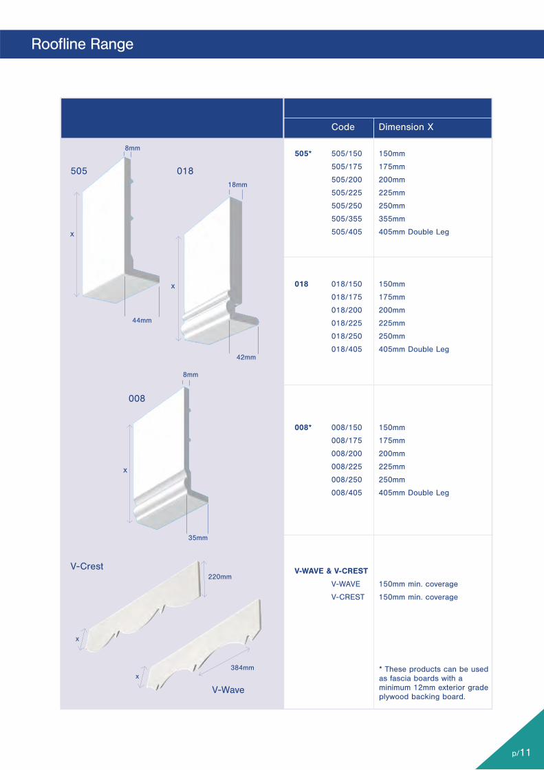
SoffitKestrel 9mm soffit boards are available in non-ventedversions for use as verge soffit or as eaves soffit when otherforms of eaves ventilation are to be used. They are alsoavailable in ventilated form and can contribute towardsproviding the necessary roof space ventilation.
Soffit is secured at maximum 600mm centres to timber using40mm Polytop pins, alternatively a wall side fix may beachieved using 692 Soffit Channel.
In properties where the outer skin of brickwork is level withthe bottom of the fascia board soffit groove, the soffit maybe extended over the brickwork and clamped using timberbattens secured to the rafter sides.
• Soffit widths should not exceed 300mm without additionalsupport.
• Soffit board fixings should not exceed 300mm across thesoffit width.
• H-section trim (691 or 693) is used to join soffit boards.• A soffit board channel (F trim or J trim) can be used to
securely locate the soffit at the wall.• Soffits can be detailed from standard soffit boards, or
Open ‘V’-Joint / Shiplap cladding.• All Open ‘V’-Joint and Shiplap cladded soffits should be
fully supported and fixed to timber bearers at max 600mmcentres along the soffit length
• It is recommended that cladding is detailed whendesigning wide soffits.
• The appropriate trims must be used in conjunction withcladded soffits (see Cladding section).
InstallationUse Stainless Steel Polytop Fixings 1 x 40mm @ 600mmCentres. Soffit widths should not exceed 300mm withoutadditional support and fixing.
Stainless Steel Polytop Fixings1 x 40mm @ 600mm Centres
803 Vented Soffit10mm Air gap
Soffit H Section691 or 693
803 Vented Soffit10mm Air gap
803 Vented Soffit10mm Air gap
Soffit H Section691 or 693
Plain Soffit
Allow 5mmexpansion gapper board endconcealed by691 soffit jointtrim
Mitred Soffit Corner
K16 & Plain Soffit to box end return
Straight Soffit Corner
Min 10mm
Roofline:
p/10
Roofline Range
K16
x
x
16mm
25mm
22mm
36mm
K22
605
KB16
x
x
x
36mm
16mm
16mm
16mm
9mm
25mm
Code Dimension X
K22 K22/150 150mm
K22/175 175mm
K22/200 200mm
K22/225 225mm
K22/250 250mm
K22/300 300mm
K22/355 355mm Double Nose
K22/405 405mm Double Nose
KB16 KB16/150 150mm
KB16/175 175mm
KB16/200 200mm
KB16/225 225mm
KB16/250 250mm
KB16/405 405mm Double Nose
K16 K16/150 150mm
K16/175 175mm
K16/200 200mm
K16/225 225mm
K16/250 250mm
K16/355 355mm Double Leg
K16/405 400mm Double Leg
K16/405/1.25 400mm Double Leg
KF16 KF16/150 150mm
KF16/175 175mm
KF16/200 200mm
KF16/225 225mm
KF16/250 250mm
KF16/405 405mm
605* 605/100 100mm
605/125 125mm
605/150 150mm
605/175 175mm
605/200 200mm
605/225 225mm
605/250 250mm
605/300 300mm
605/405 405mm
605/450 450mm
605/600 605mm
KF16
p/11
Roofline Range
V-Crest
V-Wave
018
x
x
220mm
Code Dimension X
505* 505/150 150mm
505/175 175mm
505/200 200mm
505/225 225mm
505/250 250mm
505/355 355mm
505/405 405mm Double Leg
018 018/150 150mm
018/175 175mm
018/200 200mm
018/225 225mm
018/250 250mm
018/405 405mm Double Leg
008* 008/150 150mm
008/175 175mm
008/200 200mm
008/225 225mm
008/250 250mm
008/405 405mm Double Leg
V-WAVE & V-CREST
V-WAVE 150mm min. coverage
V-CREST 150mm min. coverage
* These products can be usedas fascia boards with aminimum 12mm exterior gradeplywood backing board.
505
x
008
8mm
44mm
42mm
8mm
35mm
384mm
x
18mm
x
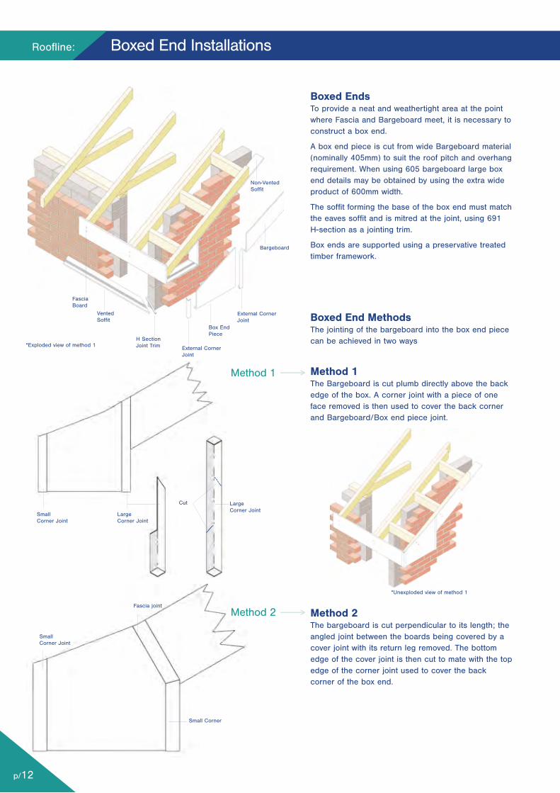
Boxed EndsTo provide a neat and weathertight area at the pointwhere Fascia and Bargeboard meet, it is necessary toconstruct a box end.
A box end piece is cut from wide Bargeboard material(nominally 405mm) to suit the roof pitch and overhangrequirement. When using 605 bargeboard large boxend details may be obtained by using the extra wideproduct of 600mm width.
The soffit forming the base of the box end must matchthe eaves soffit and is mitred at the joint, using 691H-section as a jointing trim.
Box ends are supported using a preservative treatedtimber framework.
Boxed End Methods The jointing of the bargeboard into the box end piececan be achieved in two ways
Method 1The Bargeboard is cut plumb directly above the backedge of the box. A corner joint with a piece of oneface removed is then used to cover the back cornerand Bargeboard/Box end piece joint.
Method 2The bargeboard is cut perpendicular to its length; theangled joint between the boards being covered by acover joint with its return leg removed. The bottomedge of the cover joint is then cut to mate with the topedge of the corner joint used to cover the backcorner of the box end.
SmallCorner Joint
Fascia joint
Small Corner
Roofline:
p/12
Boxed End Installations
Method 1
Method 2
FasciaBoard
VentedSoffit
*Exploded view of method 1
*Unexploded view of method 1
H SectionJoint Trim
Non-VentedSoffit
Bargeboard
External CornerJoint
SmallCorner Joint
LargeCorner Joint
LargeCorner Joint
Cut
Box EndPiece
External CornerJoint
p/13
Roofline, Cladding, Windowboards & Trims
Ventilation Products
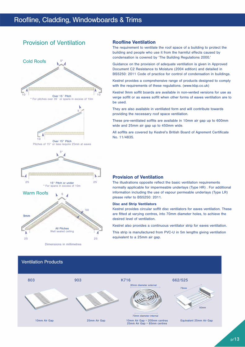
Provision of VentilationThe illustrations opposite reflect the basic ventilation requirementsnormally applicable for impermeable underlays (Type HR) . For additionalinformation including the use of vapour permeable underlays (Type LR)please refer to BS5250: 2011.
Disc and Strip VentilatorsKestrel provides circular soffit disc ventilators for eaves ventilation. Theseare fitted at varying centres, into 70mm diameter holes, to achieve thedesired level of ventilation.
Kestrel also provides a continuous ventilator strip for eaves ventilation.
This strip is manufactured from PVC-U in 5m lengths giving ventilationequivalent to a 25mm air gap.
Roofline VentilationThe requirement to ventilate the roof space of a building to protect thebuilding and people who use it from the harmful effects caused bycondensation is covered by ‘The Building Regulations 2000.’
Guidance on the provision of adequate ventilation is given in ApprovedDocument C2 Resistance to Moisture (2004 edition) and detailed inBS5250: 2011 Code of practice for control of condensation in buildings.
Kestrel provides a comprehensive range of products designed to complywith the requirements of these regulations. (www.kbp.co.uk)
Kestrel 9mm soffit boards are available in non-vented versions for use asverge soffit or as eaves soffit when other forms of eaves ventilation are tobe used.
They are also available in ventilated form and will contribute towardsproviding the necessary roof space ventilation.
These pre-ventilated soffits are available in 10mm air gap up to 600mmwide and 25mm air gap up to 450mm wide.
All soffits are covered by Kestrel’s British Board of Agrement CertificateNo. 11/4835.
803 903
Provision of Ventilation
Cold Roofs
Warm Roofs
Over 15˚ Pitch* For pitches over 35˚ or spans in excess of 10m
5*
10
10
2525
25 25
10
5
5
50
Over 15° PitchPitches of 15° or less require 25mm at eaves
15° Pitch or under* For spans in excess of 10m
All PitchesWell sealed ceiling
5*
Dimensions in millimetres
K716 662/525
10mm Air Gap 25mm Air Gap 10mm Air Gap = 200mm centres25mm Air Gap = 85mm centres
Equivalent 25mm Air Gap
50mm
79mm80mm diameter external
70mm diameter internal
9mm
Roofline:
p/14
Roofline Ventilation
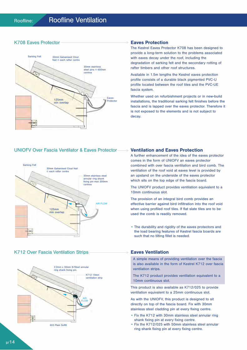
Eaves ProtectionThe Kestrel Eaves Protector K708 has been designed toprovide a long-term solution to the problems associatedwith eaves decay under the roof, including thedegradation of sarking felt and the secondary rotting ofrafter timbers and other roof structures.
Available in 1.5m lengths the Kestrel eaves protectionprofile consists of a durable black pigmented PVC-Uprofile located between the roof tiles and the PVC-UEfascia system.
Whether used on refurbishment projects or in new-buildinstallations, the traditional sarking felt finishes before thefascia and is lapped over the eaves protector. Therefore itis not exposed to the elements and is not subject todecay.
Ventilation and Eaves ProtectionA further enhancement of the idea of the eaves protectorcomes in the form of UNIOFV an eaves protectorcombined with over fascia ventilation and bird comb. Theventilation of the roof void at eaves level is provided byan upstand on the underside of the eaves protectorwhich sits on the top edge of the fascia board.
The UNIOFV product provides ventilation equivalent to a10mm continuous slot.
The provision of an integral bird comb provides aneffective barrier against bird infiltration into the roof voidwhen using profiled roof tiles. If flat slate tiles are to beused the comb is readily removed.
• The durability and rigidity of the eaves protectors andthe load bearing features of Kestrel fascia boards aresuch that no tilting fillet is needed.
Eaves VentilationA simple means of providing ventilation over the fasciais also available in the form of Kestrel K712 over fasciaventilation strips.
The K712 product provides ventilation equivalent to a10mm continuous slot.
This product is also available as K712/025 to provideventilation equivalent to a 25mm continuous slot.
As with the UNIOFV, this product is designed to sitdirectly on top of the fascia board. Fix with 30mmstainless steel cladding pin at every fixing centre.
• Fix the K712 with 30mm stainless steel annular ringshank fixing pin at every fixing centre.
• Fix the K712/025 with 50mm stainless steel annularring shank fixing pin at every fixing centre.
K708 Eaves Protector
UNIOFV Over Fascia Ventilator & Eaves Protector
K712 Over Fascia Ventilation Strips
30mm Galvanised CloutNail @ each rafter centre
30mm Galvanised Clout Nail@ each rafter centre
125mmmin overlap
EavesProtector
30mm stainless steelannular ring shankfixing pin max 200mmcentres
K712 10mmventilation strip
2.2mm x 30mm S/Steel annularring shank fixing pin.
30mm stainlesssteel pins @ 600mmcentres
Sarking Felt
Sarking Felt
603 Plain Soffit
AIR FLOW
AIRFLOW
125mmmin overlap
p/15
Soffit Range
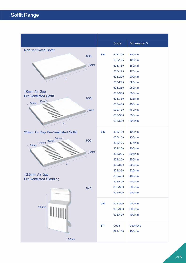
Code Dimension X
603 603/100 100mm
603/125 125mm
603/150 150mm
603/175 175mm
603/200 200mm
603/225 225mm
603/250 250mm
603/300 300mm
603/330 325mm
603/400 400mm
603/450 450mm
603/500 500mm
603/600 600mm
803 803/100 100mm
803/150 150mm
803/175 175mm
803/200 200mm
803/225 225mm
803/250 250mm
803/300 300mm
803/330 325mm
803/400 400mm
803/450 450mm
803/500 500mm
803/600 600mm
903 903/200 200mm
903/300 300mm
903/400 400mm
871 Code Coverage
871/100 100mm
Non-ventilated Soffit
10mm Air GapPre-Ventilated Soffit
25mm Air Gap Pre-Ventilated Soffit
12.5mm Air GapPre-Ventilated Cladding
603
803
903
871
9mm
9mm
9mm
38mm30mm
100mm
17.5mm
x
x
x
30mm30mm
38mm
30mm
Roofline:
p/16
Typical Jointing Details
Corner Joint Installation
Butt Joint - Plan View Corner Joint - Plan View Internal Joint Plan View
Soffit Joint Installation
Internal Joint Installation
Min 10mm
Min 5mm
Min 5mm
Expansion Gapto be 5mmper Board End
Min5mm Min
5mm
ExpansiongapsMin 5mm perboard end
Expansion Gapto be 5mmper Board End
Moveforward toposition asrequired
Move forward toposition as required
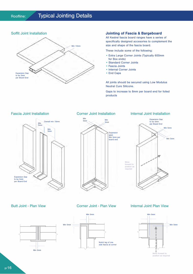
Jointing of Fascia & BargeboardAll Kestrel fascia board ranges have a series ofspecifically designed accesories to complement thesize and shape of the fascia board.
These include some of the following:
• Extra Large Corner Joints (Typically 600mm for Box ends)
• Standard Corner Joints• Fascia Joints• Internal Corner Joints• End Caps
All joints should be secured using Low ModulusNeutral Cure Silicone.
Gaps to increase to 8mm per board end for foiledproducts
Fascia Joint Installation
Overall min 10mmMin 5mm
Min 5mm
Expansion Gapto be 5mmper Board End
Min 5mm
Min 5mm Min 5mm
Min 5mmMin 5mm
Notch leg of oneside fascia at corner
p/17
Typical Jointing Details
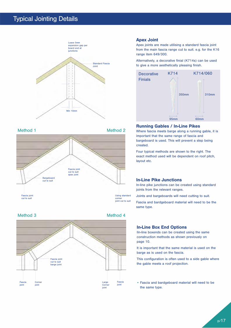
In-Line Box End OptionsIIn-line boxends can be created using the sameconstruction methods as shown previously on page 10.
It is important that the same material is used on thebarge as is used on the fascia.
This configuration is often used to a side gable wherethe gable meets a roof projection.
• Fascia and bardgeboard material will need to bethe same type.
Fascia jointcut to suitbarge joint
Fasciajoint
Fasciajoint
Cornerjoint
LargeCornerjoint
Bargeboardcut to suit
Fascia jointcut to suit
Using standardcornerjoint cut to suit
Standard FasciaJoint
Leave 5mmexpansion gap perboard end atjunctions
Fascia jointcut to suitapex joint
Method 3 Method 4
Method 1 Method 2
Apex JointApex joints are made utilising a standard fascia jointfrom the main fascia range cut to suit. e.g. for the K16range item 649/300.
Alternatively, a decorative finial (K714s) can be usedto give a more aesthetically pleasing finish.
Running Gables / In-Line PikesWhere fascia meets barge along a running gable, it isimportant that the same range of fascia andbargeboard is used. This will prevent a step beingcreated.
Four typical methods are shown to the right. Theexact method used will be dependent on roof pitch,layout etc.
In-Line Pike JunctionsIn-line pike junctions can be created using standardjoints from the relevant ranges.
Joints and bargeboards will need cutting to suit.
Fascia and bardgeboard material will need to be thesame type.
DecorativeFinials
350mm
95mm
Min 10mm
310mm
60mm
K714 K714/060

Roofline:
p/18
Working with Woodgrain Products: Roofline
Working with Woodgrain products requires slightlymodified procedures and installation processes. Overall,woodgrain products are as easy and convenient to fitand use as most other products in the Kestrel range.However, with a little extra knowledge and care at thepreparation stage, you can save yourself potentialdifficulties later on.
Kestrel’s Woodgrain foiled profiles have been extensivelytested to ensure long term weatherability and areguaranteed for use both internally and externally for aperiod of 10 years. However, non-white systems have adifferent potential for heat absorption, with resultant riskof excessive expansion and contraction. In particular,with a Woodgrain foiled coating, this heat absorption canbe significant, with potentially detrimental effects on longterm installation. Special consideration needs to be givenwhen installing Woodgrain products to minimise theamount of heat build up and provide for greater amountsof expansion.
The following additional fixing details must be followedwhen installing Woodgrain products:
Fascias/Bargeboard1. Increase expansion gap from 5mm for white to 8mm.
2. All installations to take place at ambient temperatures- between 5°C and 25°C.
3. All pre-installed products to be kept away from directsunlight, preferably indoors, at all times.
4. All joints to be made with Woodgrain corners and buttjoints.
Foiled Soffit Joint Installation Details
Foiled Fascia Joint Installation Details
Expansion Gap to be 8mm per Board End
Overall 16mm min.8mmmin.
8mmmin.
16mm min.
Expansion Gapto be 8mmper Board End
Premiergrains: Up to 3 week lead time.
WoodgrainsFoils
Blackgrain - BG
Sherwood - SG
Rosewood - PG
Whitegrain - WHG
Creamgrain - CRG
Anthracite Grey-AGG
NEWPremiergrains
Premiergrains:Up to 3 weeklead time.
Irish Oak - IOG
Mahogany - WG
p/19
Fixing Summary - Roofline
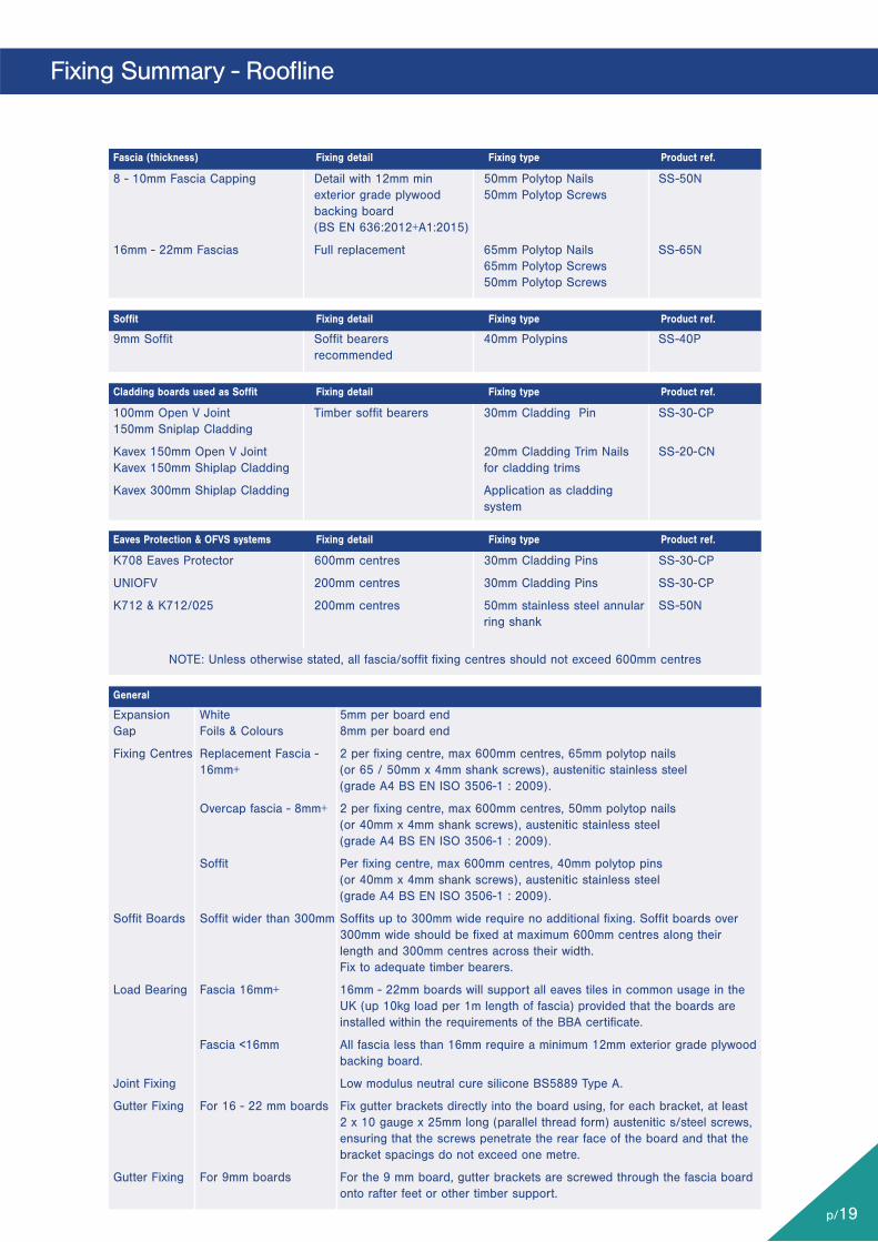
8 - 10mm Fascia Capping Detail with 12mm min 50mm Polytop Nails SS-50N exterior grade plywood 50mm Polytop Screws backing board (BS EN 636:2012+A1:2015)
16mm - 22mm Fascias Full replacement 65mm Polytop Nails SS-65N 65mm Polytop Screws 50mm Polytop Screws
9mm Soffit Soffit bearers 40mm Polypins SS-40P recommended
100mm Open V Joint Timber soffit bearers 30mm Cladding Pin SS-30-CP150mm Sniplap Cladding
Kavex 150mm Open V Joint 20mm Cladding Trim Nails SS-20-CNKavex 150mm Shiplap Cladding for cladding trims
Kavex 300mm Shiplap Cladding Application as cladding system
K708 Eaves Protector 600mm centres 30mm Cladding Pins SS-30-CP
UNIOFV 200mm centres 30mm Cladding Pins SS-30-CP
K712 & K712/025 200mm centres 50mm stainless steel annular SS-50N ring shank
NOTE: Unless otherwise stated, all fascia/soffit fixing centres should not exceed 600mm centres
Expansion White 5mm per board endGap Foils & Colours 8mm per board end
Fixing Centres Replacement Fascia - 2 per fixing centre, max 600mm centres, 65mm polytop nails 16mm+ (or 65 / 50mm x 4mm shank screws), austenitic stainless steel (grade A4 BS EN ISO 3506-1 : 2009).
Overcap fascia - 8mm+ 2 per fixing centre, max 600mm centres, 50mm polytop nails (or 40mm x 4mm shank screws), austenitic stainless steel (grade A4 BS EN ISO 3506-1 : 2009).
Soffit Per fixing centre, max 600mm centres, 40mm polytop pins (or 40mm x 4mm shank screws), austenitic stainless steel (grade A4 BS EN ISO 3506-1 : 2009).
Soffit Boards Soffit wider than 300mm Soffits up to 300mm wide require no additional fixing. Soffit boards over 300mm wide should be fixed at maximum 600mm centres along their length and 300mm centres across their width. Fix to adequate timber bearers.
Load Bearing Fascia 16mm+ 16mm - 22mm boards will support all eaves tiles in common usage in the UK (up 10kg load per 1m length of fascia) provided that the boards are installed within the requirements of the BBA certificate.
Fascia <16mm All fascia less than 16mm require a minimum 12mm exterior grade plywood backing board.
Joint Fixing Low modulus neutral cure silicone BS5889 Type A.
Gutter Fixing For 16 - 22 mm boards Fix gutter brackets directly into the board using, for each bracket, at least 2 x 10 gauge x 25mm long (parallel thread form) austenitic s/steel screws, ensuring that the screws penetrate the rear face of the board and that the bracket spacings do not exceed one metre.
Gutter Fixing For 9mm boards For the 9 mm board, gutter brackets are screwed through the fascia board onto rafter feet or other timber support.
General
Eaves Protection & OFVS systems Fixing detail Fixing type Product ref.
Cladding boards used as Soffit Fixing detail Fixing type Product ref.
Soffit Fixing detail Fixing type Product ref.
Fascia (thickness) Fixing detail Fixing type Product ref.

Cladding:
p/20
White Cladding Installations
Kestrel’s cladding systems are ideal for a wide variety ofinternal and external applications. The system is offeredcomplete with all trims, fixings and components to ensurea high quality, aesthetically appealing finish. Cladding isan ideal means of covering large areas with a durable,maintenance free solution which will stay looking good foryears. It never needs painting and is highly suitable forareas where future access could prove difficult or costly.The design features within the system mean that claddingoffers a visually appealing alternative to traditionalmaterials, whether in domestic or commercial applications.
Popular products within the cladding range and theprincipal elements of installation are detailed here.
TECHNICAL CONSIDERATIONS -InstallationThe Kestrel co-extruded PVC-UE cladding system issuitable for horizontal, vertical and diagonal fixing, as adecorative & protective external facing, over a timber studor masonry wall.
When used over a sheathed timber stud frame or over amasonry or block substrate, the cladding should be fixedto preservative treated, good quality timber battens(measuring not less than 19mm by 38mm) rigidly fixed tothe substrate at 600mm centres or closer.
Installation takes place by fixing trims around theperiphery of the area to be clad followed by installation ofthe cladding planks.
Planks are fixed using stainless steel annular ring shanknails positioned in the groove which runs along the lengthof the cladding plank. Nailing takes place from the centreof each plank working outwards.
Subsequent planks are fitted over the preceding planksensuring that the tongue-and-groove joint is firmly closedso that the nail heads are concealed by the overlap. Toavoid distortion in service, care should be taken not toinstall the cladding in extremes of temperature (i.e. below5°C or above 25°C) and to allow adequate expansiongaps of 5mm per plank end for expansion.
The cladding must be installed to provide a minimumventilated air space of 19mm between the cladding andthe backing wall. This satisfies both NHBC requirement fora minimum 10mm wide ventilation cavity and theFoundation 15 clause for a minimum 19mm cavity to bemaintained between claddings and sheathing.
Horizontal battens used to support trims at the base ofinstallations or at window heads, require 10mm diameterdrainage holes at 1000mm centres.
Horizontal Cladding
Diagonal Fixing
6812-partUniversalTrim
682UniversalTrim
Cladding
Starter Trim
Vapourpermeablewater barrier
Vapourpermeablewater barrier
19mm x 38mmbatten
4mm x 30mm Drainage SlotsMax 1000mm centres
19mm x 38mmbatten
600mmmax
425mm max
682UniversalTrim
Cladding
p/21
White Cladding Installations
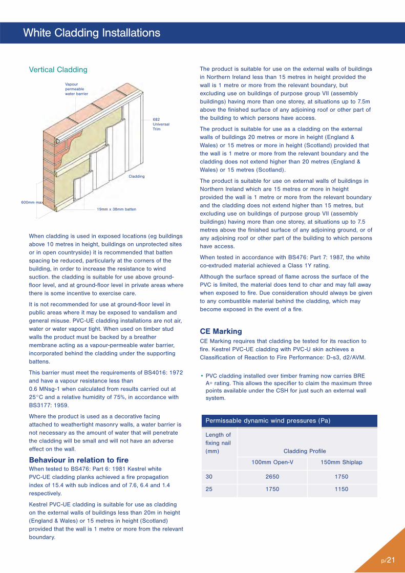
When cladding is used in exposed locations (eg buildingsabove 10 metres in height, buildings on unprotected sitesor in open countryside) it is recommended that battenspacing be reduced, particularly at the corners of thebuilding, in order to increase the resistance to windsuction. the cladding is suitable for use above ground-floor level, and at ground-floor level in private areas wherethere is some incentive to exercise care.
It is not recommended for use at ground-floor level inpublic areas where it may be exposed to vandalism andgeneral misuse. PVC-UE cladding installations are not air,water or water vapour tight. When used on timber studwalls the product must be backed by a breathermembrane acting as a vapour-permeable water barrier,incorporated behind the cladding under the supportingbattens.
This barrier must meet the requirements of BS4016: 1972and have a vapour resistance less than 0.6 MNsg-1 when calculated from results carried out at25°C and a relative humidity of 75%, in accordance withBS3177: 1959.
Where the product is used as a decorative facingattached to weathertight masonry walls, a water barrier isnot necessary as the amount of water that will penetratethe cladding will be small and will not have an adverseeffect on the wall.
Behaviour in relation to fireWhen tested to BS476: Part 6: 1981 Kestrel white PVC-UE cladding planks achieved a fire propagationindex of 15.4 with sub indices and of 7.6, 6.4 and 1.4respectively.
Kestrel PVC-UE cladding is suitable for use as claddingon the external walls of buildings less than 20m in height(England & Wales) or 15 metres in height (Scotland)provided that the wall is 1 metre or more from the relevantboundary.
Vertical Cladding
600mm max
Vapourpermeablewater barrier
19mm x 38mm batten
682UniversalTrim
Cladding
Permissable dynamic wind pressures (Pa)
Length of fixing nail (mm) Cladding Profile
100mm Open-V 150mm Shiplap
30 2650 1750
25 1750 1150
The product is suitable for use on the external walls of buildingsin Northern Ireland less than 15 metres in height provided thewall is 1 metre or more from the relevant boundary, butexcluding use on buildings of purpose group VII (assemblybuildings) having more than one storey, at situations up to 7.5mabove the finished surface of any adjoining roof or other part ofthe building to which persons have access.
The product is suitable for use as a cladding on the externalwalls of buildings 20 metres or more in height (England &Wales) or 15 metres or more in height (Scotland) provided thatthe wall is 1 metre or more from the relevant boundary and thecladding does not extend higher than 20 metres (England &Wales) or 15 metres (Scotland).
The product is suitable for use on external walls of buildings inNorthern Ireland which are 15 metres or more in heightprovided the wall is 1 metre or more from the relevant boundaryand the cladding does not extend higher than 15 metres, butexcluding use on buildings of purpose group VII (assemblybuildings) having more than one storey, at situations up to 7.5metres above the finished surface of any adjoining ground, or ofany adjoining roof or other part of the building to which personshave access.
When tested in accordance with BS476: Part 7: 1987, the whiteco-extruded material achieved a Class 1Y rating.
Although the surface spread of flame across the surface of thePVC is limited, the material does tend to char and may fall awaywhen exposed to fire. Due consideration should always be givento any combustible material behind the cladding, which maybecome exposed in the event of a fire.
CE MarkingCE Marking requires that cladding be tested for its reaction tofire. Kestrel PVC-UE cladding with PVC-U skin achieves aClassification of Reaction to Fire Performance: D-s3, d2/AVM.
• PVC cladding installed over timber framing now carries BREA+ rating. This allows the specifier to claim the maximum threepoints available under the CSH for just such an external wallsystem.
Cladding:
p/22
White Cladding Installations
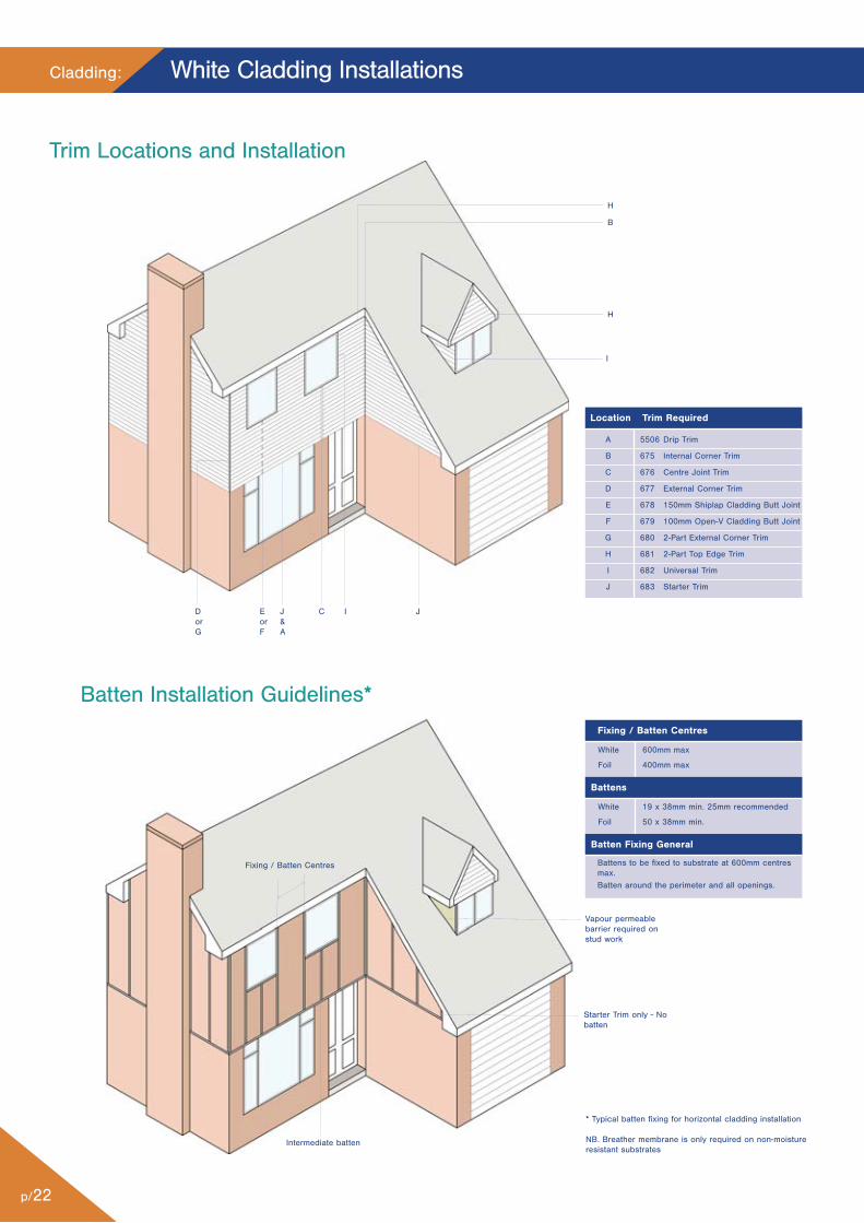
Trim Locations and Installation
H
B
H
JC IJ&A
EorF
DorG
I
Batten Installation Guidelines*
Vapour permeablebarrier required onstud work
Starter Trim only - Nobatten
Fixing / Batten Centres
Intermediate batten
White 600mm max
Foil 400mm max
Fixing / Batten Centres
White 19 x 38mm min. 25mm recommended
Foil 50 x 38mm min.
Battens
Battens to be fixed to substrate at 600mm centresmax.Batten around the perimeter and all openings.
Batten Fixing General
Location Trim Required
A 5506 Drip Trim
B 675 Internal Corner Trim
C 676 Centre Joint Trim
D 677 External Corner Trim
E 678 150mm Shiplap Cladding Butt Joint
F 679 100mm Open-V Cladding Butt Joint
G 680 2-Part External Corner Trim
H 681 2-Part Top Edge Trim
I 682 Universal Trim
J 683 Starter Trim
* Typical batten fixing for horizontal cladding installation
NB. Breather membrane is only required on non-moistureresistant substrates
p/23
White Cladding Installations
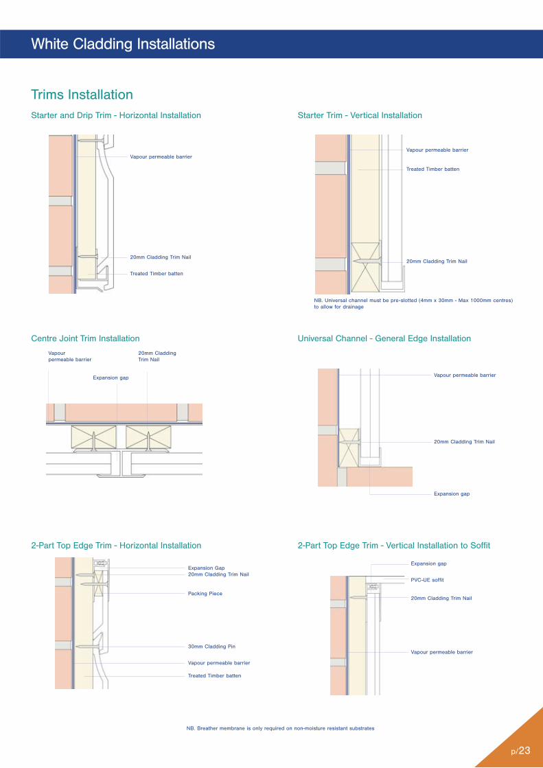
Trims Installation
Universal Channel - General Edge Installation
2-Part Top Edge Trim - Vertical Installation to Soffit
Centre Joint Trim Installation
2-Part Top Edge Trim - Horizontal Installation
NB. Breather membrane is only required on non-moisture resistant substrates
Vapour permeable barrier
20mm Cladding Trim Nail
Expansion gap
Expansion gap
PVC-UE soffit
20mm Cladding Trim Nail
Vapour permeable barrier
Expansion Gap20mm Cladding Trim Nail
Packing Piece
30mm Cladding Pin
Vapour permeable barrier
Treated Timber batten
Vapourpermeable barrier
Expansion gap
20mm CladdingTrim Nail
Starter and Drip Trim - Horizontal Installation Starter Trim - Vertical Installation
Vapour permeable barrier
20mm Cladding Trim Nail
Treated Timber batten
NB. Universal channel must be pre-slotted (4mm x 30mm - Max 1000mm centres)to allow for drainage
Vapour permeable barrier
Treated Timber batten
20mm Cladding Trim Nail
Cladding:
p/24
White Cladding Installations
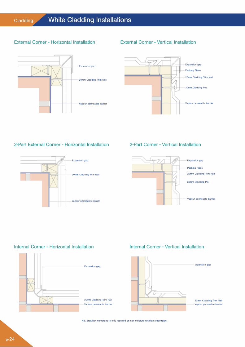
External Corner - Horizontal Installation External Corner - Vertical Installation
2-Part External Corner - Horizontal Installation 2-Part Corner - Vertical Installation
Internal Corner - Horizontal Installation Internal Corner - Vertical Installation
Expansion gap
20mm Cladding Trim Nail
Vapour permeable barrier
Expansion gap
Packing Piece
20mm Cladding Trim Nail
30mm Cladding Pin
Vapour permeable barrier
Expansion gap
20mm Cladding Trim Nail
Vapour permeable barrier
Expansion gap
Packing Piece
20mm Cladding Trim Nail
30mm Cladding Pin
Vapour permeable barrier
Expansion gap
20mm Cladding Trim Nail
Vapour permeable barrier
Expansion gap
20mm Cladding Trim Nail
Vapour permeable barrier
NB. Breather membrane is only required on non moisture resistant substrates
p/25
White Cladding Installations
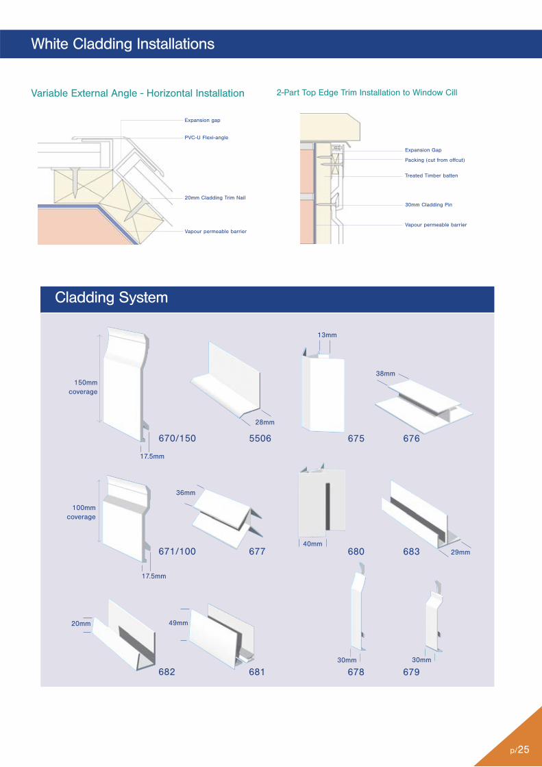
Cladding System
670/150
671/100
682 681
5506
677
675 676
680 683
678 679
150mmcoverage
38mm
29mm
13mm
17.5mm
28mm
36mm
40mm
30mm
100mmcoverage
20mm 49mm
30mm
17.5mm
Variable External Angle - Horizontal Installation 2-Part Top Edge Trim Installation to Window Cill
Expansion gap
PVC-U Flexi-angle
20mm Cladding Trim Nail
Vapour permeable barrier
Expansion Gap
Packing (cut from offcut)
Treated Timber batten
30mm Cladding Pin
Vapour permeable barrier
Cladding:
p/26
Working with Woodgrain Products: Cladding
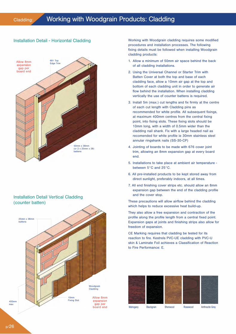
50mm x 38mm(or 2 x 25mm x 38)battens
681 TopEdge Trim
25mm x 38mmbattens
WoodgrainCladding
10mmFixing Slot
Allow 8mmexpansiongap per
board end
Allow 8mmexpansiongap per
board end
Installation Detail Vertical Cladding(counter batten)
Installation Detail - Horizontal Cladding
400mmmax
Working with Woodgrain cladding requires some modifiedprocedures and installation processes. The followingfixing details must be followed when installing Woodgraincladding products:
1. Allow a minimum of 50mm air space behind the backof all cladding installations.
2. Using the Universal Channel or Starter Trim withBatten Cover at both the top and base of eachcladding face, allow a 10mm air gap at the top andbottom of each cladding unit in order to generate airflow behind the installation. When installing claddingvertically the use of counter battens is required.
3. Install 5m (max.) cut lengths and fix firmly at the centreof each cut length with Cladding pins asrecommended for white profile. All subsequent fixings,at maximum 400mm centres from the central fixingpoint, into fixing slots. These fixing slots should be10mm long, with a width of 0.5mm wider than thecladding nail shank. Fix with a large headed nail asrecomended for white profile ie 30mm stainless steelannular ringshank nails (SS-30-CP)
4. Jointing of boards to be made with 676 cover jointtrim, allowing an 8mm expansion gap at every boardend.
5. Installations to take place at ambient air temperature -between 5°C and 25°C.
6. All pre-installed products to be kept stored away fromdirect sunlight, preferably indoors, at all times.
7. All end finishing cover strips etc. should allow an 8mmexpansion gap between the end of the cladding profileand the cover stop.
These precautions will allow airflow behind the claddingwhich helps to reduce excessive heat build-up.
They also allow a free expansion and contraction of theprofile along the profile length from a central fixed point.Expansion gaps at joints and finishing strips also allow forfreedom of expansion.
CE Marking requires that cladding be tested for itsreaction to fire. Kestrels PVC-UE cladding with PVC-Uskin & Laminate Foil achieves a Classification of Reactionto Fire Performance: E.
Mahogany Blackgrain Sherwood Rosewood Anthracite Grey
p/27
Fixing Summary - White and Foiled Cladding
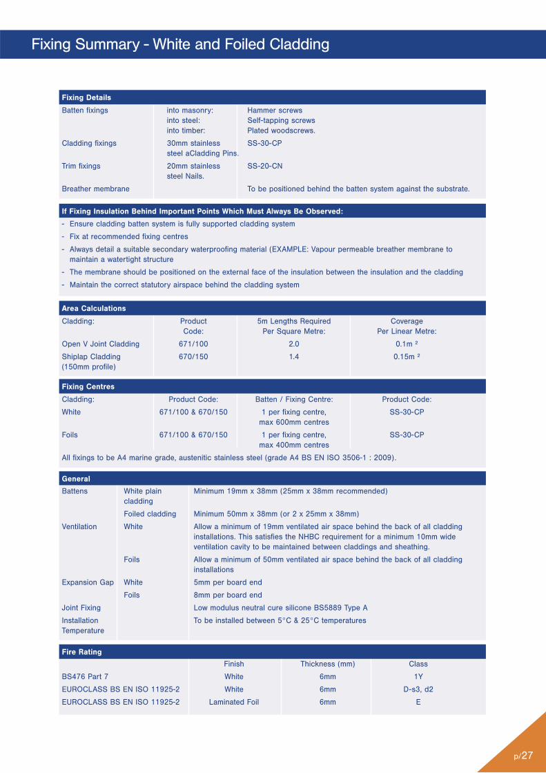
Finish Thickness (mm) Class
BS476 Part 7 White 6mm 1Y
EUROCLASS BS EN ISO 11925-2 White 6mm D-s3, d2
EUROCLASS BS EN ISO 11925-2 Laminated Foil 6mm E
Battens White plain Minimum 19mm x 38mm (25mm x 38mm recommended)cladding
Foiled cladding Minimum 50mm x 38mm (or 2 x 25mm x 38mm)
Ventilation White Allow a minimum of 19mm ventilated air space behind the back of all cladding installations. This satisfies the NHBC requirement for a minimum 10mm wide ventilation cavity to be maintained between claddings and sheathing.
Foils Allow a minimum of 50mm ventilated air space behind the back of all claddinginstallations
Expansion Gap White 5mm per board end
Foils 8mm per board end
Joint Fixing Low modulus neutral cure silicone BS5889 Type A
Installation To be installed between 5°C & 25°C temperaturesTemperature
Batten fixings into masonry: Hammer screws into steel: Self-tapping screws into timber: Plated woodscrews.
Cladding fixings 30mm stainless SS-30-CPsteel aCladding Pins.
Trim fixings 20mm stainless SS-20-CNsteel Nails.
Breather membrane To be positioned behind the batten system against the substrate.
Cladding: Product 5m Lengths Required CoverageCode: Per Square Metre: Per Linear Metre:
Open V Joint Cladding 671/100 2.0 0.1m ²
Shiplap Cladding 670/150 1.4 0.15m ²(150mm profile)
Cladding: Product Code: Batten / Fixing Centre: Product Code:
White 671/100 & 670/150 1 per fixing centre, SS-30-CPmax 600mm centres
Foils 671/100 & 670/150 1 per fixing centre, SS-30-CPmax 400mm centres
All fixings to be A4 marine grade, austenitic stainless steel (grade A4 BS EN ISO 3506-1 : 2009).
- Ensure cladding batten system is fully supported cladding system
- Fix at recommended fixing centres
- Always detail a suitable secondary waterproofing material (EXAMPLE: Vapour permeable breather membrane tomaintain a watertight structure
- The membrane should be positioned on the external face of the insulation between the insulation and the cladding
- Maintain the correct statutory airspace behind the cladding system
Fixing Details
If Fixing Insulation Behind Important Points Which Must Always Be Observed:
Area Calculations
Fixing Centres
General
Fire Rating
Cladding:
p/28
Kavex Textured Cladding Installations
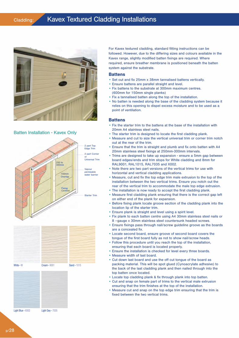
For Kavex textured cladding, standard fitting instructions can befollowed. However, due to the differing sizes and colours available in theKavex range, slightly modified batten fixings are required. Whererequired, ensure breather membrane is positioned beneath the battensystem against the substrate.
Battens• Set out and fix 25mm x 38mm tannalised battens vertically.• Ensure battens are parallel straight and level.• Fix battens to the substrate at 300mm maximum centres.
(600mm for 150mm single planks)• Fix a tannalised batten along the top of the installation.• No batten is needed along the base of the cladding system because it
relies on this opening to dispel excess moisture and to be used as apoint of ventilation.
Battens• Fix the starter trim to the battens at the base of the installation with
20mm A4 stainless steel nails.• The starter trim is designed to locate the first cladding plank.• Measure and cut to size the vertical universal trim or corner trim notch
out at the rear of the trim.• Ensure that the trim is straight and plumb and fix onto batten with A4
20mm stainless steel fixings at 250mm-300mm intervals.• Trims are designed to take up expansion - ensure a 5mm gap between
board edges/ends and trim stops for White cladding and 8mm forRAL9001, RAL1015, RAL7035 and X002.
• Note there are two part versions of the vertical trims for use withhorizontal and vertical cladding applications.
• Measure, cut and fix the top edge trim male extrusion to the top of theinstallation between the two vertical trims. Ensure you notch out therear of the vertical trim to accommodate the male top edge extrusion.
• The installation is now ready to accept the first cladding plank.• Measure first cladding plank ensuring that there is the correct gap left
on either end of the plank for expansion.• Before fixing plank locate groove section of the cladding plank into the
location lip of the starter trim.• Ensure plank is straight and level using a spirit level.• Fix plank to each batten centre using A4 30mm stainless steel nails or
8 –gauge x 30mm stainless steel countersunk headed screws.• Ensure fixings pass through nail/screw guideline groove as the boards
are a concealed fix.• Locate second board, ensure groove of second board covers the
tongue of the first board fully as not to show nail/screw heads.• Follow this procedure until you reach the top of the installation,
ensuring that each board is located properly.• Ensure the installation is checked for level every three boards.• Measure width of last board.• Cut down last board and use the off cut tongue of the board as
packing material. This will be spot glued (Cynoacrylate adhesive) tothe back of the last cladding plank and then nailed through into thetop batten once located.
• Locate top cladding plank & fix through plank into top batten.• Cut and snap on female part of trims to the vertical male extrusion
ensuring that the trim finishes at the top of the installation.• Measure cut and snap on the top edge trim ensuring that the trim is
fixed between the two vertical trims.
2 part TopEdge Trim
250 to300mm
150mmOverlap
FixingCentres
2 part CornerorUniversal Trim
Vapourpermeablewater barrier
Starter Trim
Batten Installation - Kavex Only
White - W Cream - 9001 Sand - 1015
Light Blue - X002 Light Gey - 7035
p/29
Kavex Textured Cladding Installations
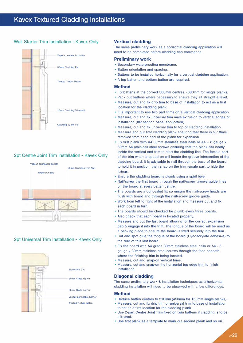
2pt Universal Trim Installation - Kavex Only
Vertical claddingThe same preliminary work as a horizontal cladding application willneed to be completed before cladding can commence.
Preliminary work• Secondary waterproofing membrane.• Batten orientation and spacing.• Battens to be installed horizontally for a vertical cladding application.• A top batten and bottom batten are required.
Method• Fix battens at the correct 300mm centres. (600mm for single planks)• Pack out battens where necessary to ensure they sit straight & level.• Measure, cut and fix drip trim to base of installation to act as a first
location for the cladding plank.• It is important to use two part trims on a vertical cladding application.• Measure, cut and fix universal trim male extrusion to vertical edges of
installation (flat section panel application).• Measure, cut and fix universal trim to top of cladding installation.• Measure and cut first cladding plank ensuring that there is 5 / 8mm
removed from each end of the plank for expansion.• Fix first plank with A4 30mm stainless steel nails or A4 – 8 gauge x
30mm A4 stainless steel screws ensuring that the plank sits neatlyinside the vertical end trim to start the cladding line. The female partof the trim when snapped on will locate the groove intersection of thecladding board. It is advisable to nail through the base of the boardto hold it in position, then snap on the trim female part to hide thefixings.
• Ensure the cladding board is plumb using a spirit level.• Nail/screw the first board through the nail/screw groove guide lines
on the board at every batten centre.• The boards are a concealed fix so ensure the nail/screw heads are
flush with board and through the nail/screw groove guide.• Work from left to right of the installation and measure cut and fix
each board in turn.• The boards should be checked for plumb every three boards.• Also check that each board is located properly.• Measure and cut the last board allowing for the correct expansion
gap & engage it into the trim. The tongue of the board will be used asa packing piece to ensure the board is fixed securely into the trim.
• Cut and spot glue the tongue of the board (Cynoacrylate adhesive) tothe rear of this last board.
• Fix the board with A4 grade 30mm stainless steel nails or A4 - 8gauge x 30mm stainless steel screws through the face beneathwhere the finishing trim is being located.
• Measure, cut and snap-on vertical trims.• Measure, cut and snap-on the horizontal top edge trim to finish
installation.
Diagonal claddingThe same preliminary work & installation techniques as a horizontalcladding installation will need to be observed with a few differences.
Method• Reduce batten centres to 210mm.(450mm for 150mm single planks).• Measure, cut and fix drip trim or universal trim to base of installation
to act as a first location for the cladding plank.• Use 2-part Centre Joint Trim fixed on twin battens if cladding is to be
mirrored.• Use first plank as a template to mark out second plank and so on.
Wall Starter Trim Installation - Kavex Only
Vapour permeable barrier
30mm Cladding Pin
Treated Timber batten
20mm Cladding Trim Nail
Cladding by others
2pt Centre Joint Trim Installation - Kavex Only
20mm Cladding Trim Nail
Vapour permeable barrier
Expansion gap
Expansion Gap
20mm Cladding Pin
30mm Cladding Pin
Vapour permeable barrier
Treated Timber batten
Cladding:
p/30
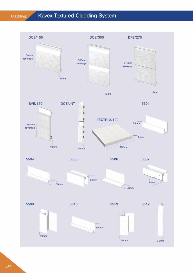
Kavex Textured Cladding System
DCE/150
5501
5504 5505
DCE/300
SVE/150 DCE/JNT
TEXTRIM/100
DFE/270
5506 5507
5509 5510 5513 5512
19mm
19mm
19mm
30mm
50mm24mm
40mm
35mm
50mm
150mmcoverage
150mmcoverage
300mmcoverage 270mm
coverage
30mm
19mm
19mm
9mm
40mm 100mm
28mm
p/31
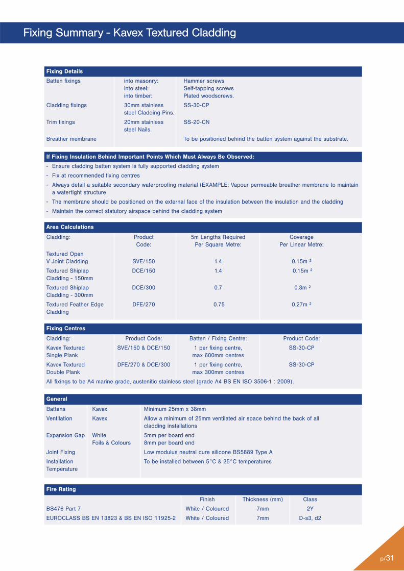
Fixing Summary - Kavex Textured Cladding
Finish Thickness (mm) Class
BS476 Part 7 White / Coloured 7mm 2Y
EUROCLASS BS EN 13823 & BS EN ISO 11925-2 White / Coloured 7mm D-s3, d2
Battens Kavex Minimum 25mm x 38mm
Ventilation Kavex Allow a minimum of 25mm ventilated air space behind the back of all cladding installations
Expansion Gap White 5mm per board endFoils & Colours 8mm per board end
Joint Fixing Low modulus neutral cure silicone BS5889 Type A
Installation To be installed between 5°C & 25°C temperaturesTemperature
Cladding: Product Code: Batten / Fixing Centre: Product Code:
Kavex Textured SVE/150 & DCE/150 1 per fixing centre, SS-30-CPSingle Plank max 600mm centres
Kavex Textured DFE/270 & DCE/300 1 per fixing centre, SS-30-CPDouble Plank max 300mm centres
All fixings to be A4 marine grade, austenitic stainless steel (grade A4 BS EN ISO 3506-1 : 2009).
Batten fixings into masonry: Hammer screws into steel: Self-tapping screws into timber: Plated woodscrews.
Cladding fixings 30mm stainless SS-30-CPsteel Cladding Pins.
Trim fixings 20mm stainless SS-20-CNsteel Nails.
Breather membrane To be positioned behind the batten system against the substrate.
Cladding: Product 5m Lengths Required CoverageCode: Per Square Metre: Per Linear Metre:
Textured Open V Joint Cladding SVE/150 1.4 0.15m ²
Textured Shiplap DCE/150 1.4 0.15m ²Cladding - 150mm
Textured Shiplap DCE/300 0.7 0.3m ²Cladding - 300mm
Textured Feather Edge DFE/270 0.75 0.27m ²Cladding
- Ensure cladding batten system is fully supported cladding system
- Fix at recommended fixing centres
- Always detail a suitable secondary waterproofing material (EXAMPLE: Vapour permeable breather membrane to maintaina watertight structure
- The membrane should be positioned on the external face of the insulation between the insulation and the cladding
- Maintain the correct statutory airspace behind the cladding system
Fixing Details
If Fixing Insulation Behind Important Points Which Must Always Be Observed:
Area Calculations
Fixing Centres
General
Fire Rating
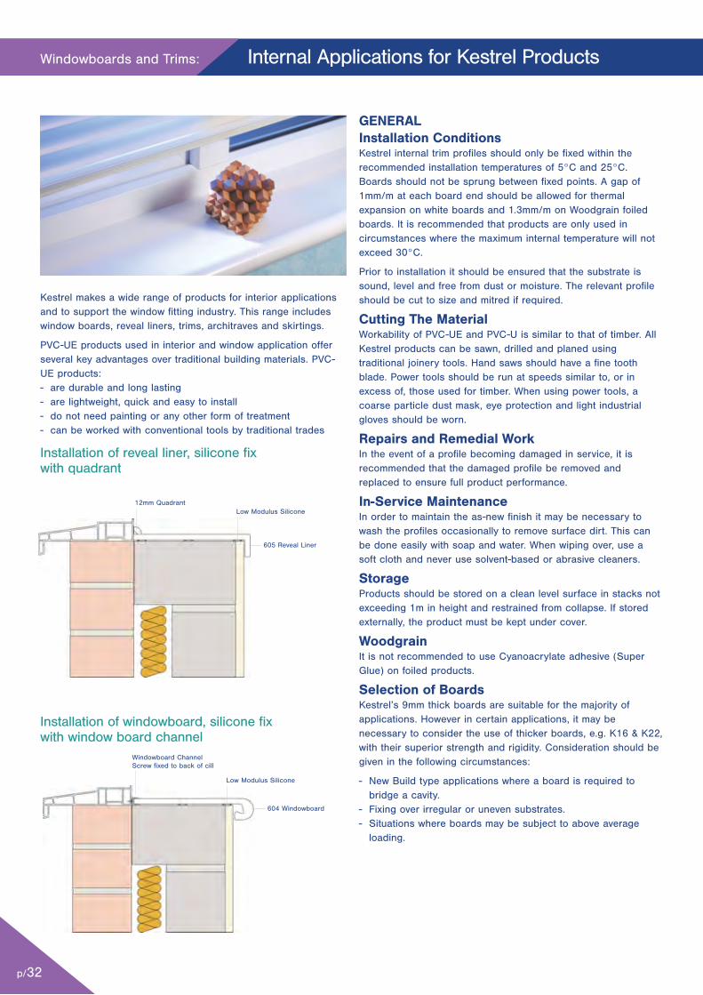
Installation of reveal liner, silicone fix with quadrant
Installation of windowboard, silicone fixwith window board channel
12mm Quadrant
Windowboard ChannelScrew fixed to back of cill
604 Windowboard
Low Modulus Silicone
605 Reveal Liner
Low Modulus Silicone
Windowboards and Trims:
p/32
Internal Applications for Kestrel Products
Kestrel makes a wide range of products for interior applicationsand to support the window fitting industry. This range includeswindow boards, reveal liners, trims, architraves and skirtings.
PVC-UE products used in interior and window application offerseveral key advantages over traditional building materials. PVC-UE products:- are durable and long lasting- are lightweight, quick and easy to install- do not need painting or any other form of treatment- can be worked with conventional tools by traditional trades
GENERALInstallation ConditionsKestrel internal trim profiles should only be fixed within therecommended installation temperatures of 5°C and 25°C.Boards should not be sprung between fixed points. A gap of1mm/m at each board end should be allowed for thermalexpansion on white boards and 1.3mm/m on Woodgrain foiledboards. It is recommended that products are only used incircumstances where the maximum internal temperature will notexceed 30°C.
Prior to installation it should be ensured that the substrate issound, level and free from dust or moisture. The relevant profileshould be cut to size and mitred if required.
Cutting The MaterialWorkability of PVC-UE and PVC-U is similar to that of timber. AllKestrel products can be sawn, drilled and planed usingtraditional joinery tools. Hand saws should have a fine toothblade. Power tools should be run at speeds similar to, or inexcess of, those used for timber. When using power tools, acoarse particle dust mask, eye protection and light industrialgloves should be worn.
Repairs and Remedial WorkIn the event of a profile becoming damaged in service, it isrecommended that the damaged profile be removed andreplaced to ensure full product performance.
In-Service MaintenanceIn order to maintain the as-new finish it may be necessary towash the profiles occasionally to remove surface dirt. This canbe done easily with soap and water. When wiping over, use asoft cloth and never use solvent-based or abrasive cleaners.
StorageProducts should be stored on a clean level surface in stacks notexceeding 1m in height and restrained from collapse. If storedexternally, the product must be kept under cover.
WoodgrainIt is not recommended to use Cyanoacrylate adhesive (SuperGlue) on foiled products.
Selection of BoardsKestrel’s 9mm thick boards are suitable for the majority ofapplications. However in certain applications, it may benecessary to consider the use of thicker boards, e.g. K16 & K22,with their superior strength and rigidity. Consideration should begiven in the following circumstances:
- New Build type applications where a board is required tobridge a cavity.
- Fixing over irregular or uneven substrates.- Situations where boards may be subject to above average
loading.
p/33
Windowboards and Trims
INSTALLATIONReveal LinerWindow board channel should be fixed to the inner surface ofthe window frame using fixing screws suitable for the windowframe material, in lengths corresponding to the reveals to becloaked. Reveal liner may also be installed without the use ofwindow board channel by butting up directly to the innerwindow frame.
Packing pieces should be introduced under the board to level itout if required. Continuous 6mm wide beads of Low ModulusSilicone should be applied to the front, middle and rear of theunderside of the board.
The board should be bedded into the substrate and, whereused, located into the window board channel. The product mayrequire to be held in place to allow the silicone to skin.
The installation should be finished by filling all gaps with acrylicSealant. Internal reveal corners can be trimmed using a slimlineinternal corner joint, applied after installation of the boards andsecured using Low Modulus Silicone. Exposed board ends aretrimmed using end caps secured with Low Modulus Silicone orCyanoacrylate adhesive.
Window BoardsInternal window boards may be fixed over existing windowboard or directly to the internal building construction, usingeither of the methods detailed. On New Build or when fixingover uneven substrates, thicker boards such as K22 and K16are recommended.
Window board channel should, if required, be fixed to the innersurface of the window frame/cill, using fixing screws suitable forthe window frame material. Where required, packing piecesshould be placed under the window board channel for support.Window board may also be installed without the use of windowboard channel by butting up directly to the window frame/cill.Packing pieces should be introduced under the board to level itout if required. Window board channel is the recommendedoption due to its positive location and the lack of a need forfurther trimming.
Continuous 6mm wide beads of Low Modulus Silicone shouldbe applied to the front, middle and rear of the underside of theboard. The board should be bedded onto the substrate andwhere used, located into the window board channel. The boardmay require to be held in position to allow the silicone to skin.The installation should be finished by filling all gaps with Acrylicsealant. Visible window board ends are finished using end capswhich may be applied with Low Modulus Silicone orCyanoacrylate adhesive.Note: It is recommended that theoverhang on all window board installations be kept to aminimum.
Skirting and ArchitravesLow Modulus Silicone should be applied in a continuous 6mmbead to the upper part of the back of the profile, and peaks ofthe same silicone applied at maximum 250mm centres to thelower part of the profile. The profile is then bedded intoposition. The profile may require holding in position to allow thesilicone to skin. The installation should then be finished byfilling gaps with acrylic sealant.
Finishing TrimsTo provide a finished appearance to installations, PVC-UE trimsshould be used. Trims are installed using Low ModulusSilicone. Following application of silicone to the rear of thetrims, they are bedded into position and when required held inposition to allow the silicone to skin.
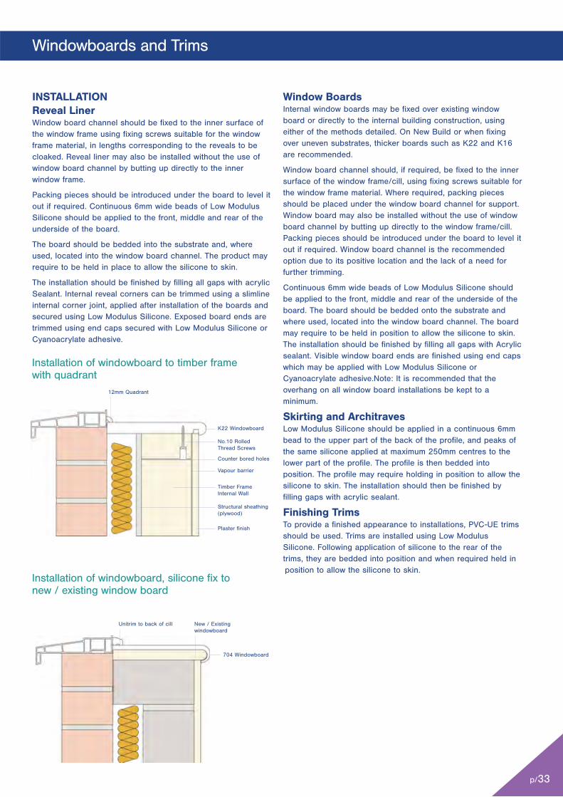
Installation of windowboard, silicone fix to new / existing window board
Unitrim to back of cill
704 Windowboard
New / Existingwindowboard
Installation of windowboard to timber framewith quadrant
12mm Quadrant
K22 Windowboard
No.10 Rolled Thread Screws
Vapour barrier
Plaster finish
Timber Frame Internal Wall
Structural sheathing(plywood)
Counter bored holes

604
K22
605
x 704
9mm
34mm
36mm
9mm
x
Code Dimension X
704 704/150 150mm
704/175 175mm
704/200 200mm
704/225 225mm
704/250 250mm
704/300 300mm
704/405 405mm Double Nose
604 604/125 155mm
604/175 205mm
604/200 230mm
604/225 255mm
604/275 305mm
604/405 470mm Double Nose
K22 K22/150 150mm
K22/175 175mm
K22/200 200mm
K22/225 225mm
K22/250 250mm
K22/300 300mm
K22/355 355mm Double Nose
K22/405 405mm Double Nose
605 605/100 100mm 605/125 125mm 605/150 150mm 605/175 175mm 605/200 200mm 605/225 225mm 605/250 250mm 605/300 300mm 605/405 405mm 605/450 450mm 605/600 605mm
*For full list of trims please see current price list.
x
x
22mm
9mm
25mm
36mm
p/34
Windowboards and Trims: Windowboard Range
*For full list of trims please see current price list.
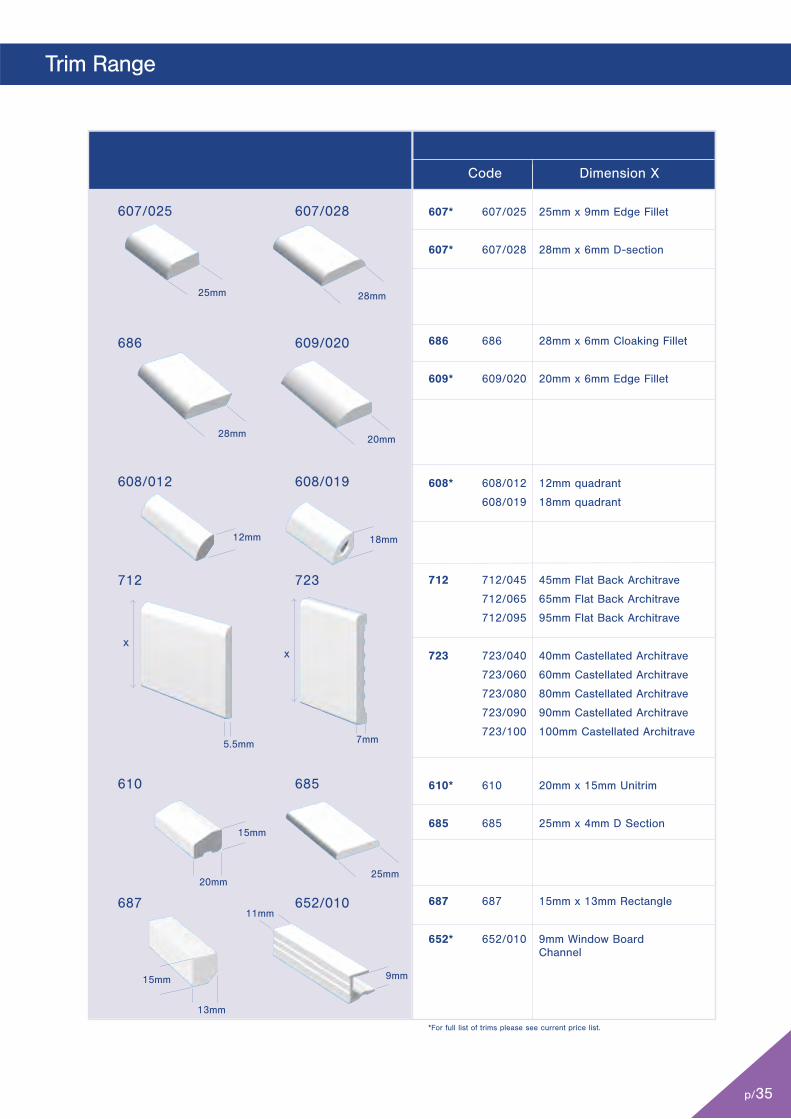
Code Dimension X
607* 607/025 25mm x 9mm Edge Fillet
607* 607/028 28mm x 6mm D-section
686 686 28mm x 6mm Cloaking Fillet
609* 609/020 20mm x 6mm Edge Fillet
608* 608/012 12mm quadrant
608/019 18mm quadrant
712 712/045 45mm Flat Back Architrave
712/065 65mm Flat Back Architrave
712/095 95mm Flat Back Architrave
723 723/040 40mm Castellated Architrave
723/060 60mm Castellated Architrave
723/080 80mm Castellated Architrave
723/090 90mm Castellated Architrave
723/100 100mm Castellated Architrave
610* 610 20mm x 15mm Unitrim
685 685 25mm x 4mm D Section
687 687 15mm x 13mm Rectangle
652* 652/010 9mm Window Board Channel
610
687
12mm
5.5mm 7mm
18mm
25mm
608/012 608/019
685
607/028
686 609/020
11mm
9mm
x
607/025
652/010
712 723
x
25mm
20mm
28mm
28mm 20mm
13mm
15mm
15mm
p/35
Trim Range
p/36
Technical Information: 10 Most Frequently Asked Questions
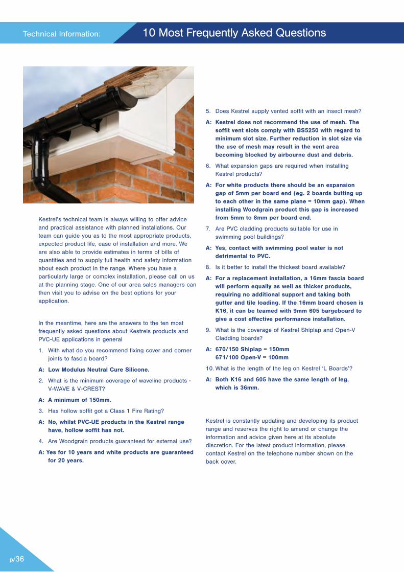
Kestrel’s technical team is always willing to offer adviceand practical assistance with planned installations. Ourteam can guide you as to the most appropriate products,expected product life, ease of installation and more. Weare also able to provide estimates in terms of bills ofquantities and to supply full health and safety informationabout each product in the range. Where you have aparticularly large or complex installation, please call on usat the planning stage. One of our area sales managers canthen visit you to advise on the best options for yourapplication.
In the meantime, here are the answers to the ten mostfrequently asked questions about Kestrels products andPVC-UE applications in general
1. With what do you recommend fixing cover and cornerjoints to fascia board?
A: Low Modulus Neutral Cure Silicone.
2. What is the minimum coverage of waveline products -V-WAVE & V-CREST?
A: A minimum of 150mm.
3. Has hollow soffit got a Class 1 Fire Rating?
A: No, whilst PVC-UE products in the Kestrel rangehave, hollow soffit has not.
4. Are Woodgrain products guaranteed for external use?
A: Yes for 10 years and white products are guaranteedfor 20 years.
5. Does Kestrel supply vented soffit with an insect mesh?
A: Kestrel does not recommend the use of mesh. Thesoffit vent slots comply with BS5250 with regard tominimum slot size. Further reduction in slot size viathe use of mesh may result in the vent areabecoming blocked by airbourne dust and debris.
6. What expansion gaps are required when installingKestrel products?
A: For white products there should be an expansiongap of 5mm per board end (eg. 2 boards butting upto each other in the same plane = 10mm gap). Wheninstalling Woodgrain product this gap is increasedfrom 5mm to 8mm per board end.
7. Are PVC cladding products suitable for use inswimming pool buildings?
A: Yes, contact with swimming pool water is notdetrimental to PVC.
8. Is it better to install the thickest board available?
A: For a replacement installation, a 16mm fascia boardwill perform equally as well as thicker products,requiring no additional support and taking bothgutter and tile loading. If the 16mm board chosen isK16, it can be teamed with 9mm 605 bargeboard togive a cost effective performance installation.
9. What is the coverage of Kestrel Shiplap and Open-VCladding boards?
A: 670/150 Shiplap = 150mm 671/100 Open-V = 100mm
10. What is the length of the leg on Kestrel ‘L Boards’?
A: Both K16 and 605 have the same length of leg,which is 36mm.
Kestrel is constantly updating and developing its productrange and reserves the right to amend or change theinformation and advice given here at its absolutediscretion. For the latest product information, pleasecontact Kestrel on the telephone number shown on theback cover.
p/37
Product Characteristics
A) TECHNICAL DATAMany of the applications for PVC foam profile are for wood-replacement products due to its ease of installation and theadvantages of a low maintenance product. The principalproducts in the Kestrel range are manufactured by co-extrudinga highly weather-able PVC-U compound (skin) onto a PVC-UEcompound (core), cooling and forming into the desired section.
In order to obtain a high quality product with the requiredstiffness, strength and impact performance, it is important tocontrol foam density, skin thickness, surface finish and cell sizedistribution. Formulations contain a mixture of processing aid,thermal stabilisers, lubricants, pigment and filler in addition tothe blowing agents required for foaming. The cellular structure isgenerated by the decomposition of chemical blowing agents, e.g.sodium bicarbonate (baking powder). The latest calcium organicstabiliser technology is utilised to provide optimal performance.Other products in the Kestrel range (rigid profile and joints) aremanufactured using conventional extrusion or injection mouldingtechniques.
OPTICAL PERFORMANCEColourThe surface colour of the profile shall be uniform and be withinthe optical limits as specified by Kestrel’s test procedure andspecification for each particular colour.
Appearance and FinishThe profile shall be free from foreign bodies, cracks or sinkmarks when viewed by normal corrected vision at 90˚ to thesurface and at a distance of 1 metre in normal diffused northlight.
Subject to normal wear and tear, Kestrel’s PVC-UE and PVC-Uprofiles will retain their optical and mechanical properties for aperiod of at least 20 years for white and 10 years for Woodgrainfoiled, with only minor changes in surface appearance.Additional care should be taken with foiled and colour finishes toensure that correct installation procedures are followed.
CLEANING & MAINTENANCEKestrel products are low maintenance and with the required careand attention will stay looking good for years to come. However,there are some external factors which may adversely affect theappearance of any PVC, especially after extended weathering:
- Solvent based cleaners- Abrasive cleaners- Environmental contamination e.g. dirt / pollen
In order to maintain the appearance, it will be necessary to washthe installation with warm soap and water to remove surface dirt.The frequency of this will depend upon the local environmentalconditions. This cleaning should be carried out with copiousamounts of soapy water to avoid any chance of scratching of thesurface.When wiping over ALWAYS use a soft cloth or sponge.NEVER use solvent-based cleaners.NEVER use abrasive cleaners.
Repairs and Remedial WorkIn the event of a profile becoming damaged in service it isrecommended that the damaged profile is removed and replacedto ensure full product performance.
DURABILITYColour FastnessAccelerated weathering tests and natural exposure trials indicatethat Kestrel products are at least as durable as conventionalwindow grade PVC-U profiles. White Kestrel PVC-UE profiles areKitemarked and satisfy UV stability and UV aged impactresistance requirements to BS7619:2010.
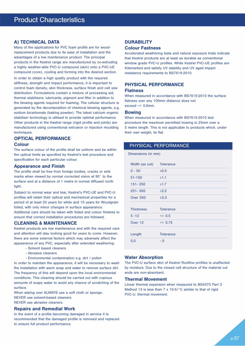
PHYSICAL PERFORMANCEFlatnessWhen measured in accordance with BS7619:2010 the surfaceflatness over any 100mm distance does not exceed +/- 0.6mm.
BowingWhen measured in accordance with BS7619:2010 testprocedure the maximum permitted bowing is 25mm over a 5 metre length. This is not applicable to products which, undertheir own weight, lie flat.
PHYSICAL PERFORMANCE
Dimensions (in mm)
Width (as cut) Tolerance
0 - 50 ±0.5
51-150 ±1.1
151- 250 ±1.7
251- 350 ±2.2
Over 350 ±3.3
Thickness Tolerance
5 -12 +/- 0.5
Over 12 +/- 0.75
Length Tolerance
5.0 - 0
Water AbsorptionThe PVC-U surface skin of Kestrel Roofline profiles is unaffectedby moisture. Due to the closed cell structure of the material cutends are non-absorbent.
Thermal MovementLinear thermal expansion when measured to BS4370 Part 3Method 13 is less than 7 x 10⁻⁵/°C similar to that of rigid PVC-U. thermal movement.
p/38
Technical Information: Product Characteristics
Thermal ConductivityCellular foam profiles have a very low co-efficient of thermalconductivity, resulting in insulation properties better thantimber boarding or gypsum plasterboard (K=0.06W/mC).
Chemical ResistanceStaining will result from contact with creosote or bitumen.Organic solvents and solvent based cleaning solutions willdamage the surface finish.
Kestrel PVC-UE profiles are liable to damage if attacked byaromatic solvents, ketones and esters. PVC-UE profiles areresistant to insect attack but may need protection duringstorage from vermin.
Fire ResistanceKestrel white cellular foam profiles do not supportcombustion and conform to the following specifications:Surface spread of flame BS476 Part 7 1997. FirePropagation BS476 Part 6 1989 (see Fixing Summary tableon opposite page).CE Marking requires that cladding betested for its reaction to fire.
Kestrel PVC-UE cladding with PVC-U skin achieves aClassification of Reaction to Fire Performance: D-s3,d2/AVM. Kestrel PVC-UE cladding with PVC-U skin &Laminate Foil achieves a Classification of Reaction to FirePerformance: E.
Impact ResistanceAll white Kestrel PVC-UE profiles are Kitemarked andcomply with the BS specification for falling weight impactresistance as specified by BS7619:2010.
Softening PointThe foamed PVC-UE material has a softening point ofapproximately 75°C.
STORAGEProfiles are protected on the co-extruded surface bypolythene lo-tac film, which should be removed immediatelyprior to installation. Kestrel PVC-UE profiles are delivered inpacks sealed in polythene sleeves, using coloured cellotapefor ease of identification of the product shades. Packquantities vary according to the profile and all packs carrya Kestrel product code indicating product, quantity anddate of manufacture.
All packs not in stillages should be unloaded by hand,stored flat in their protective packaging on a clean, levelsurface in stacks not exceeding 1 metre high andrestrained from collapse.
Where the packs are stored externally, additional protectionshould be provided against the weather and accidentaldamage. Where possible all products should be stored indoors to prevent any water ingress to the packaging andduring excessively hot weather the removal of the possibilityof heat build up and subsequent distortion of the productwithin the packaging.
B) PVC AND THE ENVIRONMENT PVC RESIN SYNTHESIS: PVC is one of the world’s oldestplastics. It has evolved since the 1940s to become a muchused, cost-effective, safe, adaptable and environmentally
efficient material. In essence, salt and oil derivatives arecombined to produce a plastic material specified for abroad range of applications across various market sectors.Production processes are being continually improved. Forthis reason, the European industry, under the auspices ofthe European Council for Vinyl Manufacturers (ECVM), hassigned a European Industry Charter, committing us all totighter limits on emissions from PVC production plants.
PVC RESIN WASTE MANAGEMENT:Plastics represent only 6% of municipal solid waste, ofwhich the PVC component is about one tenth and is mainlycomposed of used packaging. It is known that the presenceor absence of PVC in the municipal solid waste streammakes no difference to the levels of dioxins producedduring incineration.
Developed countries generate some 500 kg of waste perperson per annum. In the EU this represents 100 milliontonnes. of household waste annually. Plastic materialsaccount for 6%, of which PVC itself accounts for 0.6% intotal, i.e. 600,000 tonnes. In Western Europe only 30% isincinerated, most going to landfill.
A study of PVC undertaken by the TNO Institute ofEnvironmental and Energy Technology in Holland on behalfof the European Commission’s Director General emphasisesthat PVC can be incinerated safely and cleanly.
REPROCESSING PVC-U AND PVC-UE:During any manufacturing process, a small percentage ofscrap is generated. Kestrel reprocesses this back into themanufacturing cycle without losing any of the excellentcharacteristics of our finished products. Long termdurability, aesthetics, colour fastness and weatherresistance are not affected. Kestrel reprocesses 99.8% of allits incoming materials. The small amount of unusable scrapis disposed of, off site, at locally authorised and registeredincinerators or land fill sites.
C) STANDARDS AND CERTIFICATIONKestrel’s principal product ranges have all the necessaryapprovals for wide use in the majority of common domesticand commercial building applications.
British Board of AgreementPVC-UE Roofline System: Certificate No.11/4835PVC-UE Cladding System: Certificate No.11/4839.
BS Kitemark:Kestrel products are manufactured in accordance withBritish Standard 7619: 2010. License no. KM51726.
Company Standards:Kestrels' business and manufacturing resources have beenassessed to and are operated under ISO 9001:2008, ISO14001:2004 and BES 6001.
D) PRODUCT GUARANTEESKestrel’s white products are guaranteed for 20 years andwoodgrains for 10 years provided that approved installationand maintenance instructions are followed. Copies of theguarantees which relate to Kestrel products are availablefrom the marketing team.
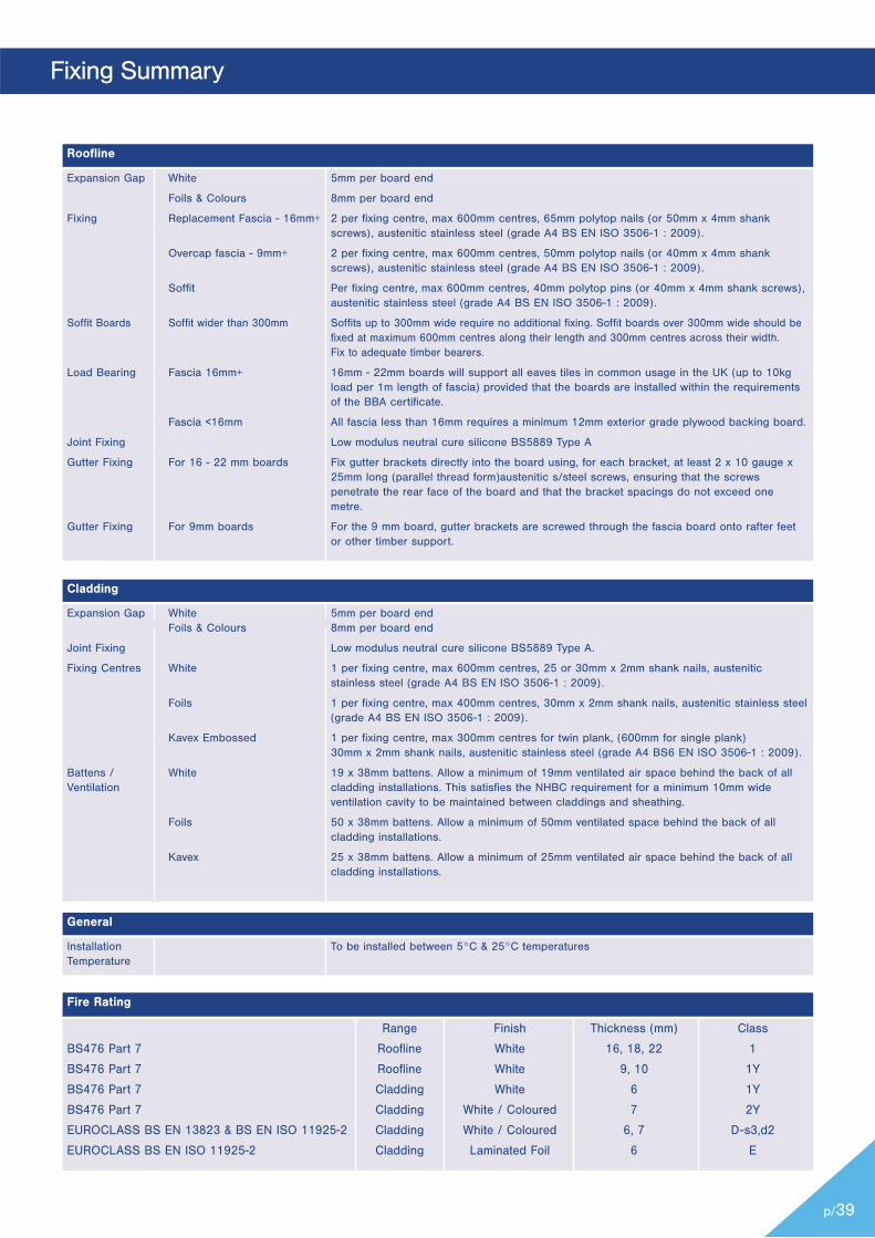
p/39
Fixing Summary
Expansion Gap White 5mm per board end
Foils & Colours 8mm per board end
Fixing Replacement Fascia - 16mm+ 2 per fixing centre, max 600mm centres, 65mm polytop nails (or 50mm x 4mm shank screws), austenitic stainless steel (grade A4 BS EN ISO 3506-1 : 2009).
Overcap fascia - 9mm+ 2 per fixing centre, max 600mm centres, 50mm polytop nails (or 40mm x 4mm shank screws), austenitic stainless steel (grade A4 BS EN ISO 3506-1 : 2009).
Soffit Per fixing centre, max 600mm centres, 40mm polytop pins (or 40mm x 4mm shank screws), austenitic stainless steel (grade A4 BS EN ISO 3506-1 : 2009).
Soffit Boards Soffit wider than 300mm Soffits up to 300mm wide require no additional fixing. Soffit boards over 300mm wide should be fixed at maximum 600mm centres along their length and 300mm centres across their width. Fix to adequate timber bearers.
Load Bearing Fascia 16mm+ 16mm - 22mm boards will support all eaves tiles in common usage in the UK (up to 10kg load per 1m length of fascia) provided that the boards are installed within the requirements of the BBA certificate.
Fascia <16mm All fascia less than 16mm requires a minimum 12mm exterior grade plywood backing board.
Joint Fixing Low modulus neutral cure silicone BS5889 Type A
Gutter Fixing For 16 - 22 mm boards Fix gutter brackets directly into the board using, for each bracket, at least 2 x 10 gauge x 25mm long (parallel thread form)austenitic s/steel screws, ensuring that the screws penetrate the rear face of the board and that the bracket spacings do not exceed one metre.
Gutter Fixing For 9mm boards For the 9 mm board, gutter brackets are screwed through the fascia board onto rafter feet or other timber support.
Roofline
Expansion Gap White 5mm per board end Foils & Colours 8mm per board end
Joint Fixing Low modulus neutral cure silicone BS5889 Type A.
Fixing Centres White 1 per fixing centre, max 600mm centres, 25 or 30mm x 2mm shank nails, austenitic stainless steel (grade A4 BS EN ISO 3506-1 : 2009).
Foils 1 per fixing centre, max 400mm centres, 30mm x 2mm shank nails, austenitic stainless steel (grade A4 BS EN ISO 3506-1 : 2009).
Kavex Embossed 1 per fixing centre, max 300mm centres for twin plank, (600mm for single plank) 30mm x 2mm shank nails, austenitic stainless steel (grade A4 BS6 EN ISO 3506-1 : 2009).
Battens / White 19 x 38mm battens. Allow a minimum of 19mm ventilated air space behind the back of all Ventilation cladding installations. This satisfies the NHBC requirement for a minimum 10mm wide ventilation cavity to be maintained between claddings and sheathing.
Foils 50 x 38mm battens. Allow a minimum of 50mm ventilated space behind the back of all cladding installations.
Kavex 25 x 38mm battens. Allow a minimum of 25mm ventilated air space behind the back of all cladding installations.
Installation To be installed between 5°C & 25°C temperaturesTemperature
Range Finish Thickness (mm) Class
BS476 Part 7 Roofline White 16, 18, 22 1
BS476 Part 7 Roofline White 9, 10 1Y
BS476 Part 7 Cladding White 6 1Y
BS476 Part 7 Cladding White / Coloured 7 2Y
EUROCLASS BS EN 13823 & BS EN ISO 11925-2 Cladding White / Coloured 6, 7 D-s3,d2
EUROCLASS BS EN ISO 11925-2 Cladding Laminated Foil 6 E
Cladding
General
Fire Rating
www.kbp.co.uk
BS 7619Lic No. KM606759
REGISTERED RECYCLER
Kestrel, Billet Lane, Normanby Enterprise Park, Normanby Road, Scunthorpe, North Lincolnshire, DN15 9YH. Tel: (01724) 400440 Fax: (01724) 280241
BES 605713
EMS 605712 FM 605711
This documentis printed onenvironmentallyfriendly paper
Kestrel is approved by the Royal Institute ofBritish Architects to provide ContinuingProfessional Development to architects andother construction professionals. We alsoprovide a range of consultative services onindividual projects, all backed up withcomprehensive technical support, literatureand CAD drawings
Dedicated Estimating TeamKestrel has a dedicated estimating team with over 20 year’s experience.
With the ability to accept electronic and hardcopy tenders anddrawings. Average turnaround time is under seven days offering99.5% accuracy and they are able to schedule from drawingsor pricing bill of quantities. This service is free of charge.
All electronic drawings should be e-mailed to:[email protected]
All paper drawings should be posted directly sent to:
Kestrel‘s Estimating Department Billet Lane,Normanby Enterprise Park,Normanby Road,Scunthorpe,North Lincolnshire,DN15 9YH.
Specification Tel : 01724 400 454 Specification Fax : 01724 280 241Specification email : [email protected]
Kestrel Customer ServicesKestrel has a dedicated Customer Services Team tohelp distributors and stockists to place their ordersor if you have any order / dispatch related enquiries.
Customer Services are available 8.30am to 5.15pm Monday to Thursday 8.30am to 5pm on Fridays.
Tel: +44 (0)8702 406107 or +44 (0)8702 406197Fax: +44 (0)8702 406116 or +44 (0)8702 406113
Order related enquires please email:[email protected]
General EnquiriesEmail: [email protected]
Sample RequestsTel: 01724 400 485Email: [email protected]
Nov 2016