Embed Size (px)
Citation preview
C H A P T E R 1 5
Editing Film
The first part of this chapter is about editing projects shot on film the traditionalway—using film equipment. The second part is about what has become a morecommon way of editing film—on video using nonlinear editing systems or lin-
ear videotape. See Chapter 1 for an overview of film editing, Chapter 13 for a dis-cussion of editing styles and techniques and Chapter 14 for more on video editing.
T R A D I T I O N A L F I L M E D I T I N G
If most people edit film on video, why do it the old-fashioned way? Well, youmight be a Luddite and want to cling to low-tech, simpler ways of working. Even ifyou’re not, there are several good reasons to edit film on film. A film workprintgives the best representation of what’s in the original camera negative. If you editfilm you’ll have a better idea of what the movie will look like when printed on film.You may already have film editing equipment and it’s cheaper to keep using it thanswitch. And you may be one of the many people who feel that the tradition and tac-tile experience of cutting and splicing pieces of celluloid is an important part ofworking in the medium. Film is the original nonlinear editing system.
EDITING EQUIPMENT
The editing bench (see Fig. 1-43) is a table that may be equipped with the following:
Cores, Reels, and RewindsIn the editing room, film is usually stored on camera cores (see Fig. 6-14).
Flatbed editing tables (see p. 593) can accommodate core-wound (tight-wound ) film.Camera raw stock comes in 2-inch cores, but 3-inch cores are better for editing-room use, as they put less stress on long rolls of film. When the film needs to be puton a reel for projection or for work on an editing bench, it is mounted on a split reel,which is made up of two halves that screw together. A flange is like half of a split reel
dfha$$3.qxd 5/31/07 9:47 Page 587
(c) 2007 Steven Ascher Excerpt from 3rd Edition - NOT MOST RECENT Filmmaker's Handbook to order 4th Edition - 2013 www.filmmakershandbook.com
not for duplication or distribution
and allows film to be wound on a core. Some flanges allow film to be wound arounditself without a core. Short takes are often stored this way.
Handle core-wound film carefully, especially if it’s not very tightly wound. Holdthe film flat like a pie, with your palm underneath; otherwise, the center may fall out(dishing). If dishing should happen, find a splice, or make a cut, and separate the twohalves. Place the half without the core on the plate of a flatbed editing table and tapethe inside end of the film to a core put in the empty center. Run the machine so theplate spins, and hold the outer end of the film in place while the inner part of theload winds onto the core. After both halves are rewound, splice them back together.
Double-key reels have two square holes on each side for mounting the reel ontoprojectors or rewinds. Single-key reels in 16mm have one square hole and one roundhole. The round hole is “idiot proofing” to prevent the film from being loaded in aprojector backward, making single-key reels good for release prints but trouble-some in the editing room.
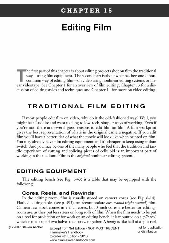
A pair of rewinds permit the film to be rewound or searched. Rewinds equippedwith a friction or tension adjustment let you increase drag on the feed side to pre-vent film from spilling (unwinding without control) during rewinding. Drag canalso be increased if rewinds develop the nasty habit of rotating by themselves. Usethe drag adjustment or your hand to put tension on the film as you rewind it. Leaveno slack between reels, because the slack may suddenly be taken up and the filmbroken. Rewinds may be fitted with long shafts to accommodate more than onereel (as when working with sound). Use an end support if more than four 16mmreels are mounted on a shaft. Use reel spacers or camera cores between reels anduse clamps to hold the whole assembly in place (see Fig. 15-1).
Fig. 15-1. Moviola rewind with long shaft, spacers, spring clamp and support. ( J & R Film)
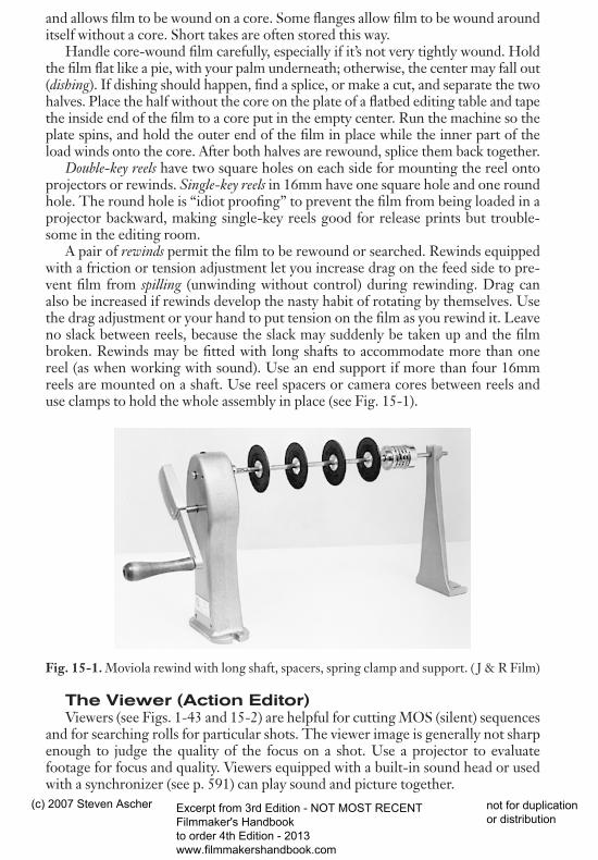
The Viewer (Action Editor)Viewers (see Figs. 1-43 and 15-2) are helpful for cutting MOS (silent) sequences
and for searching rolls for particular shots. The viewer image is generally not sharpenough to judge the quality of the focus on a shot. Use a projector to evaluatefootage for focus and quality. Viewers equipped with a built-in sound head or usedwith a synchronizer (see p. 591) can play sound and picture together.
588 THE FILMMAKER’S HANDBOOK
dfha$$3.qxd 5/31/07 9:47 Page 588
(c) 2007 Steven Ascher Excerpt from 3rd Edition - NOT MOST RECENT Filmmaker's Handbook to order 4th Edition - 2013 www.filmmakershandbook.com
not for duplication or distribution
If you are editing reversal camera origi-nal (not workprint), use a viewer with asimple film path to minimize the chance of scratching film. Never put negative in a viewer, and never whip film through aviewer at rewind speeds. The better-quality viewers allow you to mark theframe on the viewer screen with a greasepencil. Avoid devices on viewers that markthe frame by notching or nicking the film.
The SplicerIn the editing room, virtually all picture
editing is done with tape splicers that useclear Mylar tape to join pieces of film. Dur-ing projection, tape splices may throw acouple of frames out of focus at the cut and,over time, the tape may discolor. Forewarnthe lab if footage to be printed has tapesplices, since ultrasonic cleaning may re-move them (see Chapter 17).
You should generally splice on the baseside of film to avoid pulling off film emul-sion. Splicing on only one side is faster inboth making and removing the splice, but some projectors and editing machineswill only take picture spliced on both sides (double spliced ). Single-spliced picturemay jam or jump in these machines. Double splices are stronger and do not stretch(telescope) as some single splices do.
Tape is available in three basic forms: unperforated in rolls, perforated in rolls,and precut perforated. The guillotine splicer (made by various manufacturers) is usedwith unperforated tape. The tape is stretched over the film and the splicer punchesout the perforations. The tape lies across the frame line and is less visible on projec-tion. Some models also have a diagonal cut for sound editing (see below). Unperfo-rated tape is the least expensive, costing about one fourth as much as perforatedtape. The splicers themselves are fairly fragile and must be kept clean of glue andpunched perforations. The tape is relatively thin, allowing it to pass through pro-jectors well, but splices may telescope over time.
Perforated tape in roll form is used in 16mm and 35mm with the Rivas orHollywood Film splicers. Some models cut the tape straight, along the frame line,making the physical cut less obvious than on those models that cut with a jaggededge that rests in the picture area. In either case, the tape is fairly thick and is no-ticeable upon projection. These splicers need less maintenance than guillotinesplicers and do not leave little punched perforations to gum up the works. Precutsplices, the most expensive of the tape splices, are made primarily for the amateurmarket. They are very thin, easy to remove, and make the best-quality splice forpicture, but are relatively slow to apply and are not often used in the professionalediting room. Kodak Presstapes show in the picture area but can be cut with
EDITING FILM 589
Fig. 15-2. Moviola editor/viewer withthree sound heads combines synchro-nizer, viewer, and sound head. ( J & RFilm)
dfha$$3.qxd 5/31/07 9:47 Page 589
(c) 2007 Steven Ascher Excerpt from 3rd Edition - NOT MOST RECENT Filmmaker's Handbook to order 4th Edition - 2013 www.filmmakershandbook.com
not for duplication or distribution
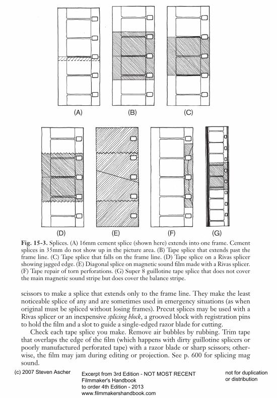
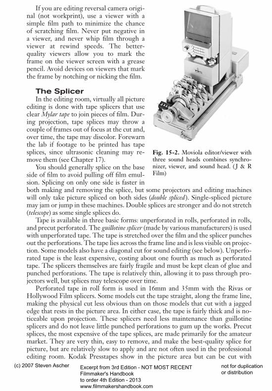
Fig. 15-3. Splices. (A) 16mm cement splice (shown here) extends into one frame. Cementsplices in 35mm do not show up in the picture area. (B) Tape splice that extends past theframe line. (C) Tape splice that falls on the frame line. (D) Tape splice on a Rivas splicershowing jagged edge. (E) Diagonal splice on magnetic sound film made with a Rivas splicer.(F) Tape repair of torn perforations. (G) Super 8 guillotine tape splice that does not coverthe main magnetic sound stripe but does cover the balance stripe.
scissors to make a splice that extends only to the frame line. They make the leastnoticeable splice of any and are sometimes used in emergency situations (as whenoriginal must be spliced without losing frames). Precut splices may be used with aRivas splicer or an inexpensive splicing block, a grooved block with registration pinsto hold the film and a slot to guide a single-edged razor blade for cutting.
Check each tape splice you make. Remove air bubbles by rubbing. Trim tapethat overlaps the edge of the film (which happens with dirty guillotine splicers orpoorly manufactured perforated tape) with a razor blade or sharp scissors; other-wise, the film may jam during editing or projection. See p. 600 for splicing magsound.
590 THE FILMMAKER’S HANDBOOK
(A) (B) (C)
(D) (E) (F) (G)
dfha$$3.qxd 5/31/07 9:47 Page 590
(c) 2007 Steven Ascher Excerpt from 3rd Edition - NOT MOST RECENT Filmmaker's Handbook to order 4th Edition - 2013 www.filmmakershandbook.com
not for duplication or distribution
CEMENT SPLICERS. Cement splicers are primarily used for splicing nega-tive before printing and for fixing or joining reels of release prints. A cement spliceis made by scraping the emulsion off one shot and then bonding the bases of thetwo shots together with fresh film cement for a strong union. One frame is lostwhere the emulsion is scraped at each cement splice.
Newer cement splicers should cut into only one of the frames at the splice.Negative splices are slightly narrower and cover less picture area than positivesplices, but, when properly made, are as strong. In 35mm, the cement splice is out-side the projected picture area, so the splice does not show on projection. In Super8 and 16mm, on the other hand, the splice does cut into the picture area and isvisible on projection. A & B roll printing allows cement splices to be hidden in thesmaller gauges (see Chapter 17). Consult Appendix I for techniques of cementsplicing.
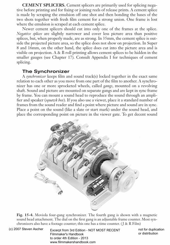
The SynchronizerA synchronizer keeps film and sound track(s) locked together in the exact same
relation to each other as you move from one part of the film to another. A synchro-nizer has one or more sprocketed wheels, called gangs, mounted on a revolvingshaft. Sound and picture are mounted on separate gangs and are kept in sync frameby frame. You can mount a sound head to reproduce the sound through an ampli-fier and speaker (squawk box). If you also use a viewer, place it a standard number offrames from the sound reader and find a point where picture and sound are in sync.Place a point on the sound (like a slate or start mark) under the sound head, andplace the corresponding point on picture in the viewer gate. To get decent sound
Fig. 15-4. Moviola four-gang synchronizer. The fourth gang is shown with a magneticsound head attachment. The dial on the first gang is an adjustable frame counter. Most syn-chronizers also have a footage counter; this one has a time counter. ( J & R Film)
EDITING FILM 591
dfha$$3.qxd 5/31/07 9:47 Page 591
(c) 2007 Steven Ascher Excerpt from 3rd Edition - NOT MOST RECENT Filmmaker's Handbook to order 4th Edition - 2013 www.filmmakershandbook.com
not for duplication or distribution
reproduction, the film has to be cranked at around 24 fps. Synchronizers are avail-able with gangs of different gauges—for example, one 16mm and one 35mm gang.
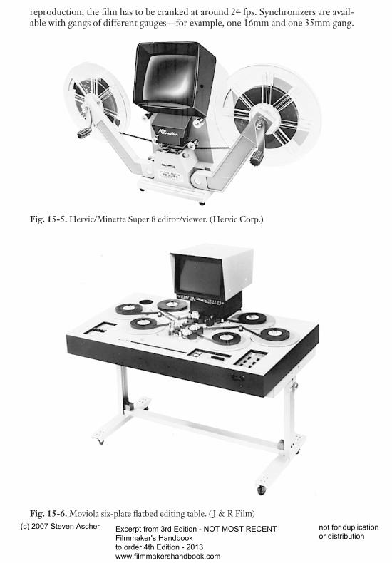
Fig. 15-5. Hervic/Minette Super 8 editor/viewer. (Hervic Corp.)
Fig. 15-6. Moviola six-plate flatbed editing table. ( J & R Film)
592 THE FILMMAKER’S HANDBOOK
dfha$$3.qxd 5/31/07 9:47 Page 592
(c) 2007 Steven Ascher Excerpt from 3rd Edition - NOT MOST RECENT Filmmaker's Handbook to order 4th Edition - 2013 www.filmmakershandbook.com
not for duplication or distribution
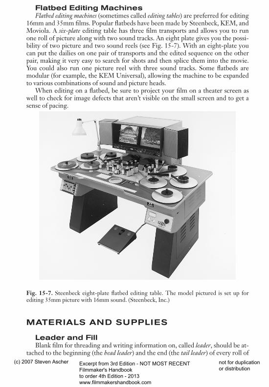
Flatbed Editing MachinesFlatbed editing machines (sometimes called editing tables) are preferred for editing
16mm and 35mm films. Popular flatbeds have been made by Steenbeck, KEM, andMoviola. A six-plate editing table has three film transports and allows you to runone roll of picture along with two sound tracks. An eight plate gives you the possi-bility of two picture and two sound reels (see Fig. 15-7). With an eight-plate youcan put the dailies on one pair of transports and the edited sequence on the otherpair, making it very easy to search for shots and then splice them into the movie.You could also run one picture reel with three sound tracks. Some flatbeds aremodular (for example, the KEM Universal), allowing the machine to be expandedto various combinations of sound and picture heads.
When editing on a flatbed, be sure to project your film on a theater screen aswell to check for image defects that aren’t visible on the small screen and to get asense of pacing.
Fig. 15-7. Steenbeck eight-plate flatbed editing table. The model pictured is set up forediting 35mm picture with 16mm sound. (Steenbeck, Inc.)
MATERIALS AND SUPPLIES
Leader and FillBlank film for threading and writing information on, called leader, should be at-
tached to the beginning (the head leader) and the end (the tail leader) of every roll of
EDITING FILM 593
dfha$$3.qxd 5/31/07 9:47 Page 593
(c) 2007 Steven Ascher Excerpt from 3rd Edition - NOT MOST RECENT Filmmaker's Handbook to order 4th Edition - 2013 www.filmmakershandbook.com
not for duplication or distribution
dailies, camera original, magnetic film, assembly, and outtakes. Use at least five tosix feet of leader at the beginning and end of each roll and write on every leader thefilm title, name of production company, and roll number, as well as “head” or “tail,”depending on its position in the roll (see Fig. 15-11).
Acetate leader is usually the least expensive and has a dull emulsion and a shinybase. Hold the film obliquely to a light source to distinguish the dull from the shinyside, or place the leader or film between slightly moistened lips or fingers to seewhich side sticks, the sticky side being the emulsion. Polyester leader has no emul-sion (both sides are shiny) and is available in a range of colors.
Slug or fill is unwanted film footage used to replace damaged sections or to prepsoundtracks for mixing. Discarded release prints used to be available from the labto be used as filler, but copyright fears have reduced this practice.
Leader and slug are available in 16mm, both single- and double-perforated. Youcan use double-perf leader as head or tail leader only if everything on the roll is double-perf. Otherwise, use single-perf so that the film will not be threaded incorrectlyand rip the single-perf sections. Because mag film is single-perf, 16mm magneticfilm must have single-perf head and tail leaders. Use single-perf slug in mag filmrolls, because double-perf slug may cause head wear and unwanted noise. Single-perf leader enables you to distinguish easily when a roll is head or tails out. Becauseof the advantages of single-perf, some editing rooms use only single-perf leadersand fill. When using magnetic film with leader or fill that has an emulsion side,make sure you splice the emulsion side of the leader to the base of magnetic film toavoid having the emulsion clog the sound heads. Avoid shrunken leader or film; itmay chatter and jam during projection.
Other SuppliesMark your workprint with China marker (grease pencil), which rubs off easily.
White and yellow are the easiest colors to see on picture. Using grease pencil onsound can clog the sound heads. Use editing gloves when you handle original orany footage that needs special care to prevent skin oils from getting on the film.Other supplies include splicing tape, fresh film cement, sharp scissors, single-edgerazor blades, film cleaner and cleaning felt, masking tape, tape for marking cans, in-delible marking pens, and a hole punch.
FILM EDITING PROCEDURES
Handling Film FootageMost films are edited with workprint, in which case the camera original should
not be stored in the editing room. However, some Super 8 and 16mm films shot onreversal stock are edited with the original. Original material is irreplaceable andneeds special care. If you are in doubt about whether a piece of reversal film isoriginal or workprint, you can generally distinguish the workprint by looking at thekey numbers (latent edge numbers). Original is almost invariably B-wind (see Fig. 7-10) and has key numbers that read through the base. Reversal workprint is A-wind, and its key numbers read through the emulsion. When working with cam-era original, keep the editing room clean and dust free. But workprint, too, should
594 THE FILMMAKER’S HANDBOOK
dfha$$3.qxd 5/31/07 9:47 Page 594
(c) 2007 Steven Ascher Excerpt from 3rd Edition - NOT MOST RECENT Filmmaker's Handbook to order 4th Edition - 2013 www.filmmakershandbook.com
not for duplication or distribution
be kept as clean as possible. At the end of each day’s work, cover the tables and binswith plastic. Keep the floor, in particular, clean. Don’t allow food and smoking inthe editing room.
Hold film by the edges to avoid getting skin oils on the picture or sound oxide.Store rolls in cans or boxes (you can get special cardboard boxes that hold a roll ofpicture and sound). Cinch marks are caused by pulling the end of a loosely woundroll to tighten it. Pushing down on the center of a tight-wound roll that has startedto dish will also cause cinch marks.
A clean workprint allows you to judge the film better. It’s likely that you’ll showthe film during the workprint stage to nonfilmmakers—investors, trial audiences,or distributors—who may have little understanding or tolerance for scratched anddirty film. When cleaning a film for a screening, use any of several commerciallyavailable cleaners, such as Kodak or Ecco film cleaner. Slightly moisten a lintlesscleaning pad or felt with cleaner and sandwich the film in the folded pad as youslowly wind the film from one end to the other. Hold the pad near the feed reel andgo slowly enough so that the cleaner will evaporate before the film is wound on thetake-up reel; otherwise, there will be a mottle on the film, which can usually be re-moved by cleaning the film again. Reposition and clean the pad often to avoid thebuildup of dirt that may scratch the film.
Assembling SequencesLike all types of editing, film editing involves going through the rushes or
dailies to select shots you want to use, then putting them together in an edited se-quence. Like nonlinear video editing, film editing allows you to add or delete shotsfrom the sequence at any point. When removing a shot, you can cut it out and re-splice the roll, shortening the sequence. Alternately, you might choose to remove asection of picture or sound and replace it with leader or fill (called slugging) tomaintain the previous length of the sequence and the sync relationship with theother track(s).
When measuring a length of leader to replace a shot, there are several ways toensure the two pieces of film are the same length. You can hold the two next to eachother to mark the length or put them in a synchronizer. Many editing tables have aframe counter much like a yardstick, on which you can measure frames. You canalso use a flatbed’s film transports to measure out longer pieces. Put the leader inone of the sound transports, and mark the first frame of leader opposite the firstframe of the shot you want to take out. Roll the film forward to the last frame andmark the leader accordingly. On some flatbeds you mark the picture frame that iscentered in the picture head and the sound frame that’s directly on the sound head.On some machines, like many Steenbecks, you can get a more precise alignment bypulling the film down against the rollers on the side. Have someone show you theproper threading for this.
While editing sequences, individual shots can be hung on pins in a trim bin ( filmbin). Some editors put the shots in order in the bin before splicing them into a se-quence. As noted above, when working on an eight-plate flatbed, it’s easy to takeshots directly from the dailies to the rough cut without hanging them in bins first.Some people like to use two flatbeds—one to search footage and the other to runthe edited cut.
EDITING FILM 595
dfha$$3.qxd 5/31/07 9:47 Page 595
(c) 2007 Steven Ascher Excerpt from 3rd Edition - NOT MOST RECENT Filmmaker's Handbook to order 4th Edition - 2013 www.filmmakershandbook.com
not for duplication or distribution
Trimming and ReconstitutingWhen you remove an entire shot or a section from the head or tail (a trim), hang it
in a trim bin. Keep the bin organized by sequence or by edge code number so you canfind footage when you want it. On feature films, editors may use trim tabs or cinetabs,which are small slips of cardboard hung in the bin to identify the shot on a given pin.
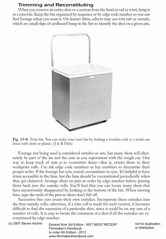
Fig. 15-8. Trim bin. You can make your own bin by bolting a wooden rack to a trash canlined with cloth or plastic. ( J & R Film)
Footage not being used is considered outtakes or outs, but many shots will alter-nately be part of the ins and the outs as you experiment with the rough cut. Oneway to keep track of outs is to reconstitute them—that is, return them to theirworkprint rolls. Use ink edge code numbers or key numbers to determine theirproper order. If the footage has sync sound, reconstitute in sync. It’s helpful to havetrims accessible in the bins, but the bins should be reconstituted periodically whenthey get cluttered. Arrange shots on pins in order by edge number before puttingthem back into the outtake rolls. You’ll find that you can locate many shots thathave mysteriously disappeared by looking at the bottom of the bin. When movingbins, tape the ends of the pins so shots don’t fall off.
Successive fine cuts create their own outtakes. Incorporate these outtakes intothe first outtake rolls; otherwise, if a trim roll is made for each version, it becomesdifficult to find the extension of a particular shot, since it could be on any one of anumber of rolls. It is easy to locate the extension of a shot if all the outtakes are re-constituted by edge number.
596 THE FILMMAKER’S HANDBOOK
dfha$$3.qxd 5/31/07 9:47 Page 596
(c) 2007 Steven Ascher Excerpt from 3rd Edition - NOT MOST RECENT Filmmaker's Handbook to order 4th Edition - 2013 www.filmmakershandbook.com
not for duplication or distribution
Things to Watch Out For
FLASH FRAMES. Check the beginning and end of each shot for flash frames(overexposed frames caused by the camera stopping with the shutter open or whenthe camera changes speed at the beginning or end of a take). Hold the end of theshot up to a white wall or a light box and look for variations in exposure. You mustcheck carefully, since often a drastically overexposed frame is surrounded by severalsubtly overexposed ones. If you see a slight flashing at cuts when viewing the movie,this may mean you’ve left in some flash frames.
CUTTING FRAMES. When the negative is cut prior to printing, at least onecutting frame (also called cutback frame) is needed at the head and tail of each shot tomake the cement splice (see Chapter 17). If you are using two parts of the same take(a split shot), delete and put aside some frames of workprint between the two shotsto allow for the cement splice. Some negative cutters lose only one frame, espe-cially if they are warned that it is a split shot, but others, as a matter of course, leavea frame or more at each end of every shot pulled from the original. To be safe, youmay want to leave three or more unused cutting frames between the shots. Thenumber of unused cutting frames is sometimes called the cut margin.
FADES AND DISSOLVES. Unless blowups or other special printing isneeded, films are generally printed on contact printers (see Chapter 17). Contactprinters usually make fades and dissolves in lengths of 16, 24, 32, 48, 64, or 96frames. Optical printers are not restricted in fade lengths. Check with your lab tosee what is available. A 48-frame fade or dissolve is fairly standard. The first and lastquarters of these effects often show little noticeable change (that is, the first 12frames of a 48-frame fade-in look dark, the last 12 have nearly full exposure), sothey seem to go by quicker than the frame count would suggest. If one shot is to dis-solve into another, find the overlapping frames. For example, a 48-frame dissolvehas a 48-frame overlap, 24 frames from each shot (see Fig. 15-9). Check the overlapto make sure there are no flash frames or unwanted movements. Store theworkprint of the overlap frames in a special place so it can be checked at any timefor sufficient length. Too often, the negative cutter comes across a marked dissolveon the workprint and cannot find the extension in the original.
SHOTS WITHOUT KEY NUMBERS. Short shots (those fewer than 20frames in 16mm) may not have a key number (see Fig. 7-11). Write the closest keynumber on the shot in grease pencil to aid the negative cutter when he or she isconforming (see Chapter 17). If for some reason an entire roll lacks key numbers,this may be a workprinting error (see p. 663) or because the original lacks key num-bers. Consider having ink edge code (see p. 602) applied to the original andworkprint before editing. Workprint without key numbers can be matched to theoriginal by eye, but this is very difficult if the location of the shot on the roll of the original is not known. Shots with a lot of camera or subject movement are the easiest to eyeball. Find frames with distinctive movement, line up the original and workprint in a synchronizer, and roll them in sync to find the head and tail ofthe shot.
EDITING FILM 597
dfha$$3.qxd 5/31/07 9:47 Page 597
(c) 2007 Steven Ascher Excerpt from 3rd Edition - NOT MOST RECENT Filmmaker's Handbook to order 4th Edition - 2013 www.filmmakershandbook.com
not for duplication or distribution
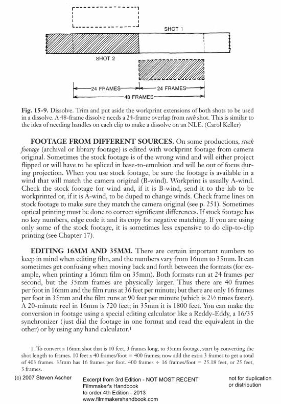
Fig. 15-9. Dissolve. Trim and put aside the workprint extensions of both shots to be usedin a dissolve. A 48-frame dissolve needs a 24-frame overlap from each shot. This is similar tothe idea of needing handles on each clip to make a dissolve on an NLE. (Carol Keller)
FOOTAGE FROM DIFFERENT SOURCES. On some productions, stockfootage (archival or library footage) is edited with workprint footage from cameraoriginal. Sometimes the stock footage is of the wrong wind and will either projectflipped or will have to be spliced in base-to-emulsion and will be out of focus dur-ing projection. When you use stock footage, be sure the footage is available in awind that will match the camera original (B-wind). Workprint is usually A-wind.Check the stock footage for wind and, if it is B-wind, send it to the lab to beworkprinted or, if it is A-wind, to be duped to change winds. Check frame lines onstock footage to make sure they match the camera original (see p. 251). Sometimesoptical printing must be done to correct significant differences. If stock footage hasno key numbers, edge code it and its copy for negative matching. If you are usingonly some of the stock footage, it is sometimes less expensive to do clip-to-clipprinting (see Chapter 17).
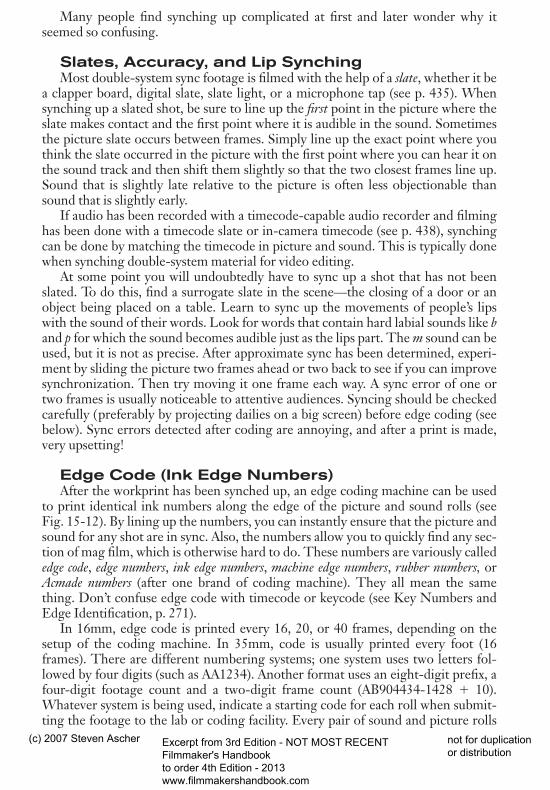
EDITING 16MM AND 35MM. There are certain important numbers tokeep in mind when editing film, and the numbers vary from 16mm to 35mm. It cansometimes get confusing when moving back and forth between the formats (for ex-ample, when printing a 16mm film on 35mm). Both formats run at 24 frames persecond, but the 35mm frames are physically larger. Thus there are 40 frames per foot in 16mm and the film runs at 36 feet per minute; but there are only 16 framesper foot in 35mm and the film runs at 90 feet per minute (which is 21⁄2 times faster).A 20-minute reel in 16mm is 720 feet; in 35mm it is 1800 feet. You can make theconversion in footage using a special editing calculator like a Reddy-Eddy, a 16/35synchronizer ( just dial the footage in one format and read the equivalent in theother) or by using any hand calculator.1
1. To convert a 16mm shot that is 10 feet, 3 frames long, to 35mm footage, start by converting theshot length to frames. 10 feet x 40 frames/foot � 400 frames; now add the extra 3 frames to get a total of 403 frames. 35mm has 16 frames per foot. 400 frames � 16 frames/foot � 25.18 feet, or 25 feet, 3 frames.
598 THE FILMMAKER’S HANDBOOK
dfha$$3.qxd 5/31/07 9:47 Page 598
(c) 2007 Steven Ascher Excerpt from 3rd Edition - NOT MOST RECENT Filmmaker's Handbook to order 4th Edition - 2013 www.filmmakershandbook.com
not for duplication or distribution
REEL LENGTH. Films are divided into manageable lengths for editing, mix-ing and printing called reels. A typical film will be made up of several reels. In16mm, reels more than 1000 to 1200 feet (27 to 33 minutes) are awkward to workwith in the editing room. Though it is possible to print 16mm in longer lengths,some labs prefer that reels not exceed 1200 feet to minimize handling damage. Thestandard 35mm editing reel is about 10 minutes (1000 feet), though 35mm filmsare generally printed and released on 2000-foot reels (22 minutes). Talk to the laband mixing facility for their preferences. If you’re cramped for space on the reel, re-member that the head and tail of the reel are reserved for printing leaders; themovie itself can’t be as long as the reel. When you’re done editing, the reels need tobe balanced, so each reel is full (or nearly so) with the last reel shorter if necessary.Be attentive to the scenes at which reel breaks take place, particularly the first sceneon a new reel. Avoid having reel breaks in midscene or where music is playing orbefore scenes with important information (in case the projectionist messes up thetransition from one reel to the next). The heads and tails of reels tend to get a lot ofwear and tear, so try to avoid very light scenes which show dirt more.
After a film is printed, the reels are often spliced together for projection orshown alternately on two projectors, using a changeover device. See 35mm ReleasePrints, p. 687, for inscribing changeover marks on the release prints. See p. 691 forspecial precautions when preparing sound tracks for multireel films.
MAGNETIC TRACKS AND SYNCHINGDAILIES
Sound TransferSound is recorded during production with an audio recorder using one of a vari-
ety of formats—hard drive, memory card, 1⁄4-inch tape, DAT, etc. In traditionalfilm editing, the audio is then transferred to sprocketed magnetic film (also calledmag stock or mag) for editing with the picture.
In 16mm, editing is done with fullcoat, which has sprocket holes like camera filmbut, like audiotape, is covered on one side with a brown or black oxide for record-ing the sound. In 35mm, editing may be done with stripe, which looks like clearcamera film but has a thin strip of oxide for the sound and a balance stripe on theother edge.
Sound transfers may take as long as two hours to transfer one hour of tape.Sound is usually transferred while the picture is being processed. Sound is trans-ferred by playing the original sound and rerecording it on a magnetic film recorder,or dubber. (The word dubbing comes from “doubling”—that is, “to copy.” Dubberis sometimes used to mean a machine that only plays back magnetic film.) Manymodern recording devices have precise speed control, but older tape machines willneed to be resolved to ensure proper speed during transfer. For more on resolving,see Speed Control for Sync Recording, p. 389.
If a reference tone was recorded on the original tape, use it to set the recordinglevel during transfer. The transfer level will normally be set so that the tone reads 0 dB on the transfer equipment’s VU meter. But the reference tone is just a startingpoint; the level needs to be checked on the actual program material. If the transfers
EDITING FILM 599
dfha$$3.qxd 5/31/07 9:47 Page 599
(c) 2007 Steven Ascher Excerpt from 3rd Edition - NOT MOST RECENT Filmmaker's Handbook to order 4th Edition - 2013 www.filmmakershandbook.com
not for duplication or distribution
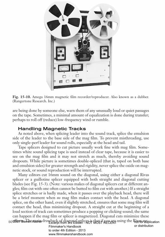
Fig. 15-10. Amega 16mm magnetic film recorder/reproducer. Also known as a dubber.(Rangertone Research. Inc.)
are being done by someone else, warn them of any unusually loud or quiet passageson the tape. Sometimes, a minimal amount of equalization is done during transfer;perhaps to roll off (reduce) low-frequency wind or rumble.
Handling Magnetic TracksAs noted above, when splicing leader into the sound track, splice the emulsion
side of the leader to the base side of the mag film. To prevent misthreading, useonly single-perf leader for sound rolls, especially at the head and tail.
Tape splicers designed to cut picture usually work fine with mag film. Some-times white sound splicing tape is used instead of clear tape, because it is easier tosee on the mag film and it may not stretch as much, thereby avoiding sounddropouts. While picture is sometimes double-spliced (that is, taped on both baseand emulsion sides) for greater strength and rigidity, never splice the oxide on mag-netic stock, or sound reproduction will be interrupted.
Many editors cut 16mm sound on the diagonal, using either a diagonal Rivassplicer or a guillotine splicer equipped with both straight and diagonal cuttingblades (see Fig. 15-3). (Note: various makes of diagonal splicers cut at different an-gles; film cut with one often cannot be butted to film cut with another.) If a straightsplice stretches or is badly made, when it passes over the playback head, there willbe a brief moment when no mag film makes contact with the head. A diagonalsplice, on the other hand, even if slightly stretched, ensures that some mag film willcontact the head, thus minimizing dropout. A straight cut at the beginning of aloud section of track can sometimes produce a popping or clicking sound; the samecan happen if the mag film or splicer is magnetized. Diagonal cuts minimize theseeffects. The main drawback of diagonal splices is that if you are using the Rivas sys-
600 THE FILMMAKER’S HANDBOOK
dfha$$3.qxd 5/31/07 9:47 Page 600
(c) 2007 Steven Ascher Excerpt from 3rd Edition - NOT MOST RECENT Filmmaker's Handbook to order 4th Edition - 2013 www.filmmakershandbook.com
not for duplication or distribution
tem, you will need to use two splicers. If noisy splices indicate that your splicer ismagnetized, demagnetize it immediately with a bulk eraser or a hand degausser.Make several test splices on blank mag film, and listen closely with the playbackvolume all the way up. This is best done on a dubber to avoid being misled by me-chanical noises at the splice (which are heard on some flatbeds).
Synching UpWhen shooting with a video camera, sound and picture are usually recorded to-
gether right on the videotape; they are already in sync and ready to be viewed oredited. When shooting film, picture and sound are recorded separately (double sys-tem), and the picture has to be put back together with the sound before editing be-gins. This process is called synchronizing the dailies, synching the rushes, or, morecommonly, just synching up (pronounced “sinking”). When synching is complete,every sync-sound shot on the picture is matched frame for frame to the soundtrack; each roll of picture has a roll of mag film of equal length that can be playedback with it.
In most sync filming, there is more audio recorded than picture. This is becausethe sound recorder is turned on before and off after the camera and because otherwild sound (perhaps for sound effects) is recorded when the camera is not running.(Of course, there is also a certain amount of MOS—silent—picture.) Some editorsremove all the wild sound during synching and spool it up on separate rolls. Othersleave most of it in place and splice the same length of leader or fill into the pictureto keep it even with the sound roll. In general, no footage should be removed fromthe picture roll during synching unless absolutely necessary: moving picture fromone roll to another can result in confusion when searching for footage, and throw-ing picture away is often regretted later.
Synching up requires an editing machine such as a Steenbeck or Moviola, or anediting bench equipped with rewinds, a synchronizer, viewer, sound head, and am-plifier. There are many methods of synching up; one is outlined in Appendix G.
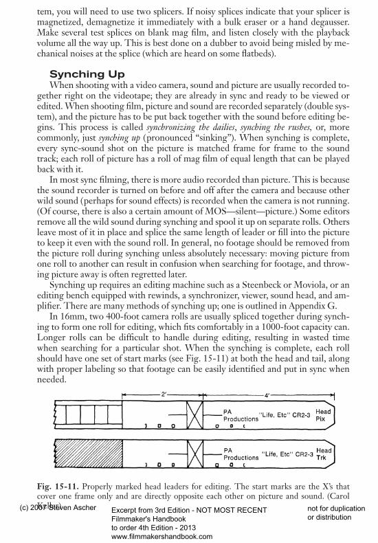
In 16mm, two 400-foot camera rolls are usually spliced together during synch-ing to form one roll for editing, which fits comfortably in a 1000-foot capacity can.Longer rolls can be difficult to handle during editing, resulting in wasted timewhen searching for a particular shot. When the synching is complete, each rollshould have one set of start marks (see Fig. 15-11) at both the head and tail, alongwith proper labeling so that footage can be easily identified and put in sync whenneeded.
Fig. 15-11. Properly marked head leaders for editing. The start marks are the X’s thatcover one frame only and are directly opposite each other on picture and sound. (CarolKeller)
EDITING FILM 601
dfha$$3.qxd 5/31/07 9:47 Page 601
(c) 2007 Steven Ascher Excerpt from 3rd Edition - NOT MOST RECENT Filmmaker's Handbook to order 4th Edition - 2013 www.filmmakershandbook.com
not for duplication or distribution
Many people find synching up complicated at first and later wonder why itseemed so confusing.
Slates, Accuracy, and Lip SynchingMost double-system sync footage is filmed with the help of a slate, whether it be
a clapper board, digital slate, slate light, or a microphone tap (see p. 435). Whensynching up a slated shot, be sure to line up the first point in the picture where theslate makes contact and the first point where it is audible in the sound. Sometimesthe picture slate occurs between frames. Simply line up the exact point where youthink the slate occurred in the picture with the first point where you can hear it onthe sound track and then shift them slightly so that the two closest frames line up.Sound that is slightly late relative to the picture is often less objectionable thansound that is slightly early.
If audio has been recorded with a timecode-capable audio recorder and filminghas been done with a timecode slate or in-camera timecode (see p. 438), synchingcan be done by matching the timecode in picture and sound. This is typically donewhen synching double-system material for video editing.
At some point you will undoubtedly have to sync up a shot that has not beenslated. To do this, find a surrogate slate in the scene—the closing of a door or anobject being placed on a table. Learn to sync up the movements of people’s lipswith the sound of their words. Look for words that contain hard labial sounds like band p for which the sound becomes audible just as the lips part. The m sound can beused, but it is not as precise. After approximate sync has been determined, experi-ment by sliding the picture two frames ahead or two back to see if you can improvesynchronization. Then try moving it one frame each way. A sync error of one ortwo frames is usually noticeable to attentive audiences. Syncing should be checkedcarefully (preferably by projecting dailies on a big screen) before edge coding (seebelow). Sync errors detected after coding are annoying, and after a print is made,very upsetting!
Edge Code (Ink Edge Numbers)After the workprint has been synched up, an edge coding machine can be used
to print identical ink numbers along the edge of the picture and sound rolls (seeFig. 15-12). By lining up the numbers, you can instantly ensure that the picture andsound for any shot are in sync. Also, the numbers allow you to quickly find any sec-tion of mag film, which is otherwise hard to do. These numbers are variously callededge code, edge numbers, ink edge numbers, machine edge numbers, rubber numbers, orAcmade numbers (after one brand of coding machine). They all mean the samething. Don’t confuse edge code with timecode or keycode (see Key Numbers andEdge Identification, p. 271).
In 16mm, edge code is printed every 16, 20, or 40 frames, depending on thesetup of the coding machine. In 35mm, code is usually printed every foot (16frames). There are different numbering systems; one system uses two letters fol-lowed by four digits (such as AA1234). Another format uses an eight-digit prefix, afour-digit footage count and a two-digit frame count (AB904434-1428 � 10).Whatever system is being used, indicate a starting code for each roll when submit-ting the footage to the lab or coding facility. Every pair of sound and picture rolls
602 THE FILMMAKER’S HANDBOOK
dfha$$3.qxd 5/31/07 9:47 Page 602
(c) 2007 Steven Ascher Excerpt from 3rd Edition - NOT MOST RECENT Filmmaker's Handbook to order 4th Edition - 2013 www.filmmakershandbook.com
not for duplication or distribution
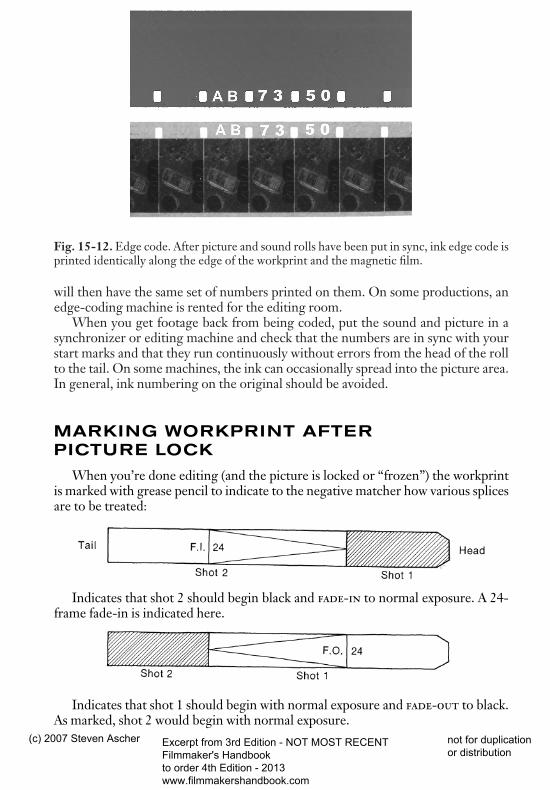
Fig. 15-12. Edge code. After picture and sound rolls have been put in sync, ink edge code isprinted identically along the edge of the workprint and the magnetic film.
will then have the same set of numbers printed on them. On some productions, anedge-coding machine is rented for the editing room.
When you get footage back from being coded, put the sound and picture in asynchronizer or editing machine and check that the numbers are in sync with yourstart marks and that they run continuously without errors from the head of the rollto the tail. On some machines, the ink can occasionally spread into the picture area.In general, ink numbering on the original should be avoided.
MARKING WORKPRINT AFTER PICTURE LOCK
When you’re done editing (and the picture is locked or “frozen”) the workprintis marked with grease pencil to indicate to the negative matcher how various splicesare to be treated:
Indicates that shot 2 should begin black and fade-in to normal exposure. A 24-frame fade-in is indicated here.
Indicates that shot 1 should begin with normal exposure and fade-out to black.As marked, shot 2 would begin with normal exposure.
EDITING FILM 603
dfha$$3.qxd 5/31/07 9:47 Page 603
(c) 2007 Steven Ascher Excerpt from 3rd Edition - NOT MOST RECENT Filmmaker's Handbook to order 4th Edition - 2013 www.filmmakershandbook.com
not for duplication or distribution

Indicates a dissolve between shots 1 and 2. Note that this is simply a fade-outthat overlaps a fade-in.
Indicates a double exposure of shots 1 and 2 so that both will be visible simulta-neously. This marking is also used for superimposed titles. The beginning and endof shot 2 are cut and spliced into their proper place, indicating the extent of thedouble exposure. Include enough frames so that there is a key number in eachpiece.
The extended scene marking is used when a piece of workprint has to be re-placed with leader because of torn or damaged frames. The arrow indicates towhich scene the frames of leader belong.
The unintentional splice mark indicates that a shot has been cut in editingand then put back together, so no cut should be made in the original (normally, the negative matcher will plan to cut the original anywhere he finds a splice in theworkprint). A careful matcher should check to make sure all splices are intentionalregardless of the mark. You can make splices even clearer by putting vertical linesdown the center of all intentional splices. It is a good idea to put vertical lines tomark the extent of fades and dissolves and to write their lengths in numbers on
604 THE FILMMAKER’S HANDBOOK
dfha$$3.qxd 5/31/07 9:47 Page 604
(c) 2007 Steven Ascher Excerpt from 3rd Edition - NOT MOST RECENT Filmmaker's Handbook to order 4th Edition - 2013 www.filmmakershandbook.com
not for duplication or distribution

A P P E N D I X F
A COMPARISON OF RUNNING TIMES ANDFORMATS OF 8MM, SUPER 8, 16MM, AND
35MM MOTION PICTURE FILMS
dfha$$3.qxd 5/31/07 9:48 Page 782
(c) 2007 Steven Ascher Excerpt from 3rd Edition - NOT MOST RECENT Filmmaker's Handbook to order 4th Edition - 2013 www.filmmakershandbook.com
not for duplication or distribution
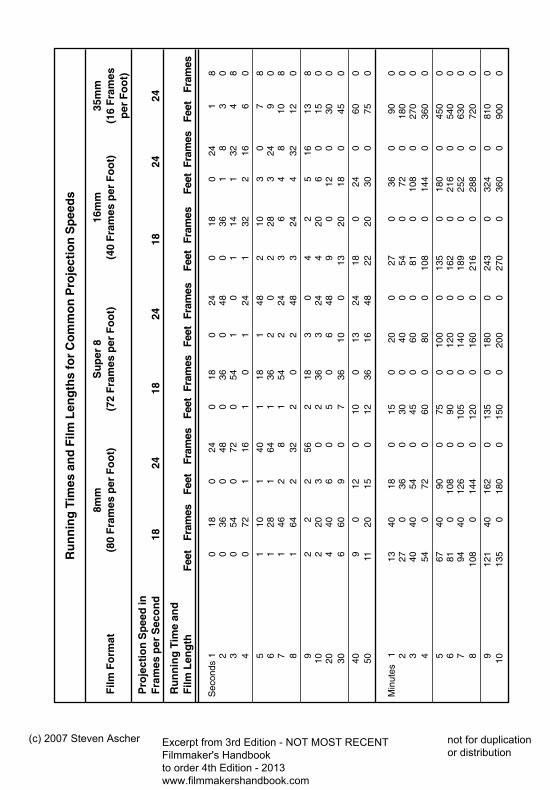
Ru
nn
ing
Tim
es a
nd
Film
Len
gth
s fo
r C
om
mo
n P
roje
ctio
n S
pee
ds
8mm
Su
per
816
mm
35m
mF
ilm F
orm
at(8
0 F
ram
es p
er F
oo
t)(7
2 F
ram
es p
er F
oo
t)(4
0 F
ram
es p
er F
oo
t)(1
6 F
ram
esp
er F
oo
t)
Pro
ject
ion
Sp
eed
in
Fra
mes
per
Sec
on
d18
2418
2418
2424
Ru
nn
ing
Tim
e an
d
Film
Len
gth
Feet
Fram
esFe
etFr
ames
Feet
Fram
esFe
etFr
ames
Fe
etFr
ames
Feet
Fram
esFe
etFr
ames
Sec
onds
10
180
240
180
240
180
241
82
036
048
036
048
036
18
30
30
540
720
541
01
141
324
84
072
116
10
124
132
216
60
51
101
401
181
482
103
07
86
128
164
136
20
228
324
90
71
462
81
542
243
64
810
88
164
232
20
248
324
432
120
92
22
562
183
04
25
1613
810
220
30
236
324
420
60
150
204
406
05
06
489
012
030
030
660
90
736
100
1320
180
450
409
012
010
013
2418
024
060
050
1120
150
1236
1648
2220
300
750
Min
utes
1
1340
180
150
200
270
360
900
227
036
030
040
054
072
018
00
340
4054
045
060
081
010
80
270
04
540
720
600
800
108
014
40
360
0
567
4090
075
010
00
135
018
00
450
06
810
108
090
012
00
162
021
60
540
07
9440
126
010
50
140
018
90
252
063
00
810
80
144
012
00
160
021
60
288
072
00
912
140
162
013
50
180
024
30
324
081
00
1013
50
180
015
00
200
027
00
360
090
00
dfha$$3.qxd 5/31/07 9:48 Page 783
(c) 2007 Steven Ascher Excerpt from 3rd Edition - NOT MOST RECENT Filmmaker's Handbook to order 4th Edition - 2013 www.filmmakershandbook.com
not for duplication or distribution
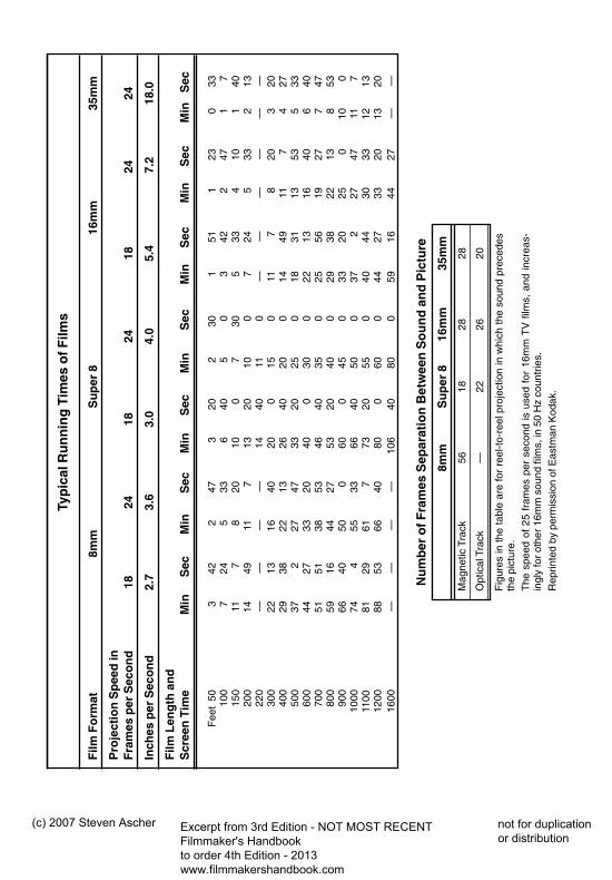
Typ
ical
Ru
nn
ing
Tim
es o
f Film
s
Film
Fo
rmat
8mm
Su
per
816
mm
35m
m
Pro
ject
ion
Sp
eed
in
Fra
mes
per
Sec
on
d18
2418
2418
2424
Inch
es p
er S
eco
nd
2.7
3.6
3.0
4.0
5.4
7.2
18.0
Film
Len
gth
an
d
Scr
een
Tim
eM
inS
ecM
inS
ecM
inS
ecM
inS
ecM
inS
ecM
in
Sec
Min
Sec
Fee
t50
342
247
320
230
151
123
033
100
724
533
640
50
342
247
17
150
117
820
100
730
533
410
140
200
1449
117
1320
100
724
533
213
220
——
——
1440
110
——
——
——
300
2213
1640
200
150
117
820
320
400
2938
2213
2640
200
1449
117
427
50
037
227
4733
2025
018
3113
535
33
600
4427
3320
400
300
2213
1640
640
70
051
5138
5346
4035
025
5619
277
4780
059
1644
2753
2040
029
3822
138
5390
066
4050
060
045
033
2025
010
010
0074
455
3366
4050
037
227
4711
7 11
0081
2961
773
2055
040
4430
3312
1312
0088
5366
4080
060
044
2733
2013
2016
00—
——
—10
640
800
5916
4427
——
Nu
mb
er o
f Fra
mes
Sep
arat
ion
Bet
wee
n S
ou
nd
an
d P
ictu
re
8mm
Su
per
816
mm
35m
m
Mag
netic
Tra
ck56
1828
28
Opt
ical
Tra
ck—
2226
20
Fig
ures
in th
e ta
ble
are
for
reel
-to-
reel
pro
ject
ion
in w
hich
the
soun
d pr
eced
esth
e pi
ctur
e.T
he s
peed
of
25 f
ram
es p
er s
econ
d is
use
d fo
r 16
mm
TV
film
s, a
nd in
crea
s-in
gly
for
othe
r 16
mm
sou
nd fi
lms,
in 5
0 H
z co
untr
ies.
Rep
rinte
d by
per
mis
sion
of E
astm
an K
odak
.
dfha$$3.qxd 5/31/07 9:48 Page 784
(c) 2007 Steven Ascher Excerpt from 3rd Edition - NOT MOST RECENT Filmmaker's Handbook to order 4th Edition - 2013 www.filmmakershandbook.com
not for duplication or distribution
A P P E N D I X G
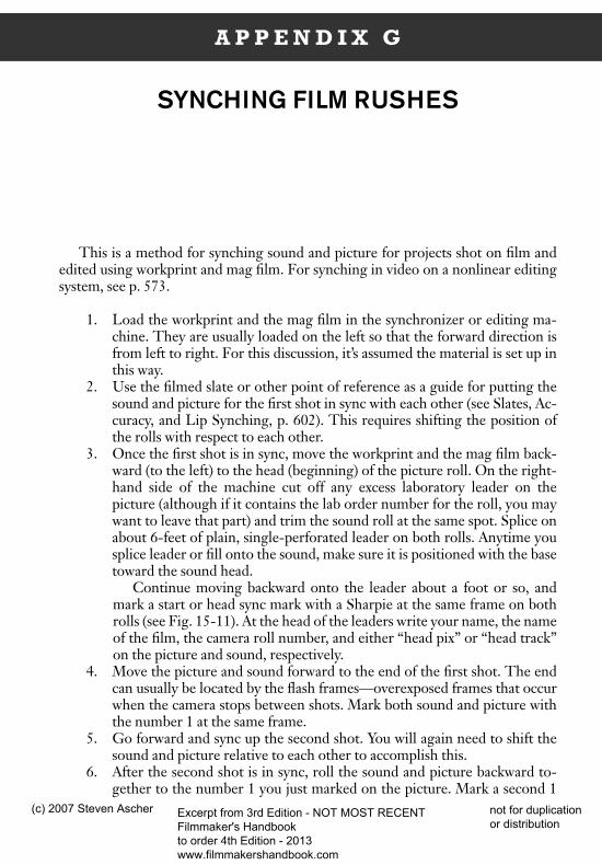
SYNCHING FILM RUSHES
This is a method for synching sound and picture for projects shot on film andedited using workprint and mag film. For synching in video on a nonlinear editingsystem, see p. 573.
1. Load the workprint and the mag film in the synchronizer or editing ma-chine. They are usually loaded on the left so that the forward direction isfrom left to right. For this discussion, it’s assumed the material is set up inthis way.
2. Use the filmed slate or other point of reference as a guide for putting thesound and picture for the first shot in sync with each other (see Slates, Ac-curacy, and Lip Synching, p. 602). This requires shifting the position ofthe rolls with respect to each other.
3. Once the first shot is in sync, move the workprint and the mag film back-ward (to the left) to the head (beginning) of the picture roll. On the right-hand side of the machine cut off any excess laboratory leader on thepicture (although if it contains the lab order number for the roll, you maywant to leave that part) and trim the sound roll at the same spot. Splice onabout 6-feet of plain, single-perforated leader on both rolls. Anytime yousplice leader or fill onto the sound, make sure it is positioned with the basetoward the sound head.
Continue moving backward onto the leader about a foot or so, andmark a start or head sync mark with a Sharpie at the same frame on bothrolls (see Fig. 15-11). At the head of the leaders write your name, the nameof the film, the camera roll number, and either “head pix” or “head track”on the picture and sound, respectively.
4. Move the picture and sound forward to the end of the first shot. The endcan usually be located by the flash frames—overexposed frames that occurwhen the camera stops between shots. Mark both sound and picture withthe number 1 at the same frame.
5. Go forward and sync up the second shot. You will again need to shift thesound and picture relative to each other to accomplish this.
6. After the second shot is in sync, roll the sound and picture backward to-gether to the number 1 you just marked on the picture. Mark a second 1
dfha$$3.qxd 5/31/07 9:48 Page 785
(c) 2007 Steven Ascher Excerpt from 3rd Edition - NOT MOST RECENT Filmmaker's Handbook to order 4th Edition - 2013 www.filmmakershandbook.com
not for duplication or distribution
on the sound at the same frame. Search through the sound roll by hand tofind the first 1 you marked on it.
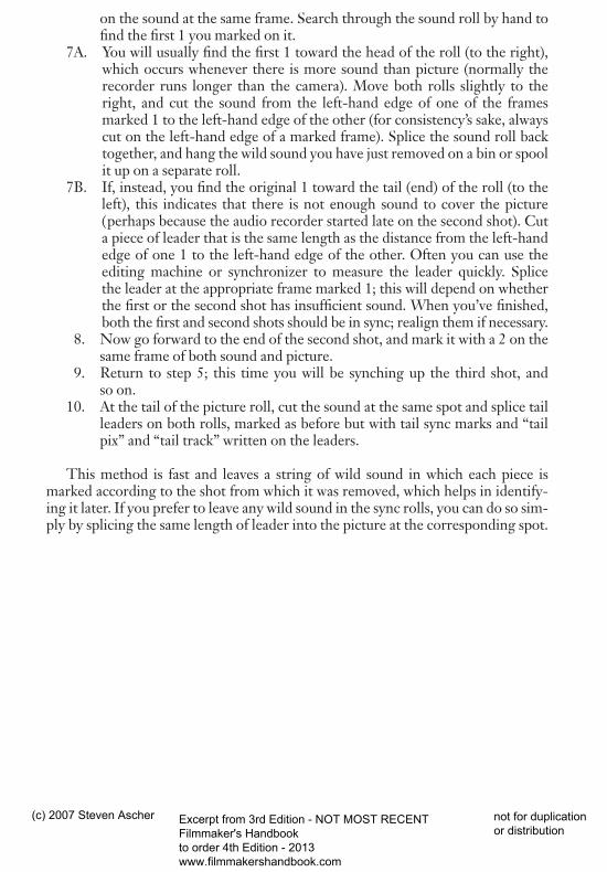
7A. You will usually find the first 1 toward the head of the roll (to the right),which occurs whenever there is more sound than picture (normally therecorder runs longer than the camera). Move both rolls slightly to theright, and cut the sound from the left-hand edge of one of the framesmarked 1 to the left-hand edge of the other (for consistency’s sake, alwayscut on the left-hand edge of a marked frame). Splice the sound roll backtogether, and hang the wild sound you have just removed on a bin or spoolit up on a separate roll.
7B. If, instead, you find the original 1 toward the tail (end) of the roll (to theleft), this indicates that there is not enough sound to cover the picture(perhaps because the audio recorder started late on the second shot). Cuta piece of leader that is the same length as the distance from the left-handedge of one 1 to the left-hand edge of the other. Often you can use theediting machine or synchronizer to measure the leader quickly. Splice the leader at the appropriate frame marked 1; this will depend on whetherthe first or the second shot has insufficient sound. When you’ve finished,both the first and second shots should be in sync; realign them if necessary.
8. Now go forward to the end of the second shot, and mark it with a 2 on thesame frame of both sound and picture.
9. Return to step 5; this time you will be synching up the third shot, and so on.
10. At the tail of the picture roll, cut the sound at the same spot and splice tailleaders on both rolls, marked as before but with tail sync marks and “tailpix” and “tail track” written on the leaders.
This method is fast and leaves a string of wild sound in which each piece ismarked according to the shot from which it was removed, which helps in identify-ing it later. If you prefer to leave any wild sound in the sync rolls, you can do so sim-ply by splicing the same length of leader into the picture at the corresponding spot.
786 APPENDIX G
dfha$$3.qxd 5/31/07 9:48 Page 786
(c) 2007 Steven Ascher Excerpt from 3rd Edition - NOT MOST RECENT Filmmaker's Handbook to order 4th Edition - 2013 www.filmmakershandbook.com
not for duplication or distribution
A P P E N D I X H
SPLITTING 16MM AND 35MM MAG TRACKS PRIOR TO THE MIX
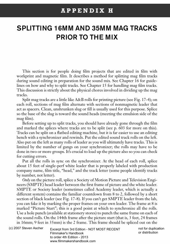
This section is for people doing film projects that are edited in film withworkprint and magnetic film. It describes a method for splitting mag film tracksduring sound editing in preparation for the sound mix. See Chapter 16 for guide-lines on how and why to split tracks. See Chapter 15 for handling mag film tracks.This discussion is strictly about the physical chores involved in dividing up the magtracks.
Split mag tracks are a little like A&B rolls for printing picture (see Fig. 17-4); oneach roll, sections of mag film alternate with sections of nonmagnetic leader thatact as spacers. Clean, unshrunken slug or fill is usually used for this purpose. Spliceso the base of the slug is toward the sound heads (meeting the emulsion side of themag film).
Before setting up to split tracks, you should have already gone through the filmand marked the splices where tracks are to be split (see p. 603 for more on this).Tracks can be split on a flatbed editing machine, but it is far easier to use an editingbench with a synchronizer and rewinds. Put the edited sound track rolls on the left.Also put on the left as many rolls of leader as you will ultimately have tracks. This islimited by the number of gangs on your synchronizer; the rolls may have to bedone in two or more groups. It’s crucial to load up the picture also so you can checkfor cutting errors.
Put all the rolls in sync on the synchronizer. At the head of each roll, spliceabout 15 feet of single-perf white leader that is properly labeled with productioncompany name, film title, “head,” and the track letter (some people identify tracksby number, not letter).
Only on the picture roll, splice a Society of Motion Picture and Television Engi-neers (SMPTE) head leader between the first frame of picture and the white leader.SMPTE or Society leader (sometimes called Academy leader, which is actually adifferent system) contains the familiar countdown from 8 to 2, followed by a shortsection of black leader (see Fig. 17-8). If you can’t get SMPTE leader from the lab,you can fake it by marking the proper frames on your own leader. The frame at 8 ismarked “Picture Start”; this is a good point at which to synchronize all the rolls.Use a hole punch (available at stationery stores) to punch the same frame on each ofthe sound rolls. On the 144th frame after the picture start (that is, 3 feet, 24 framesin 16mm; 9 feet in 35mm) is the 2 frame. This frame should be spliced out on the
dfha$$3.qxd 5/31/07 9:48 Page 787
(c) 2007 Steven Ascher Excerpt from 3rd Edition - NOT MOST RECENT Filmmaker's Handbook to order 4th Edition - 2013 www.filmmakershandbook.com
not for duplication or distribution
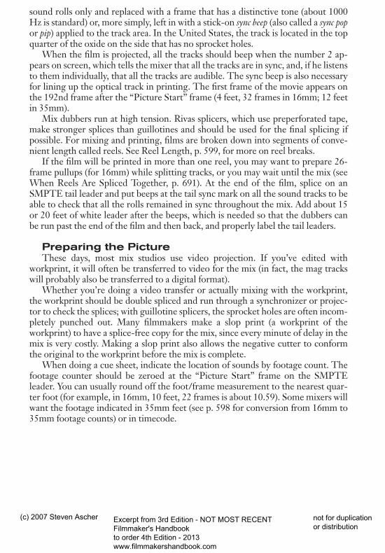
sound rolls only and replaced with a frame that has a distinctive tone (about 1000Hz is standard) or, more simply, left in with a stick-on sync beep (also called a sync popor pip) applied to the track area. In the United States, the track is located in the topquarter of the oxide on the side that has no sprocket holes.
When the film is projected, all the tracks should beep when the number 2 ap-pears on screen, which tells the mixer that all the tracks are in sync, and, if he listensto them individually, that all the tracks are audible. The sync beep is also necessaryfor lining up the optical track in printing. The first frame of the movie appears onthe 192nd frame after the “Picture Start” frame (4 feet, 32 frames in 16mm; 12 feetin 35mm).
Mix dubbers run at high tension. Rivas splicers, which use preperforated tape,make stronger splices than guillotines and should be used for the final splicing ifpossible. For mixing and printing, films are broken down into segments of conve-nient length called reels. See Reel Length, p. 599, for more on reel breaks.
If the film will be printed in more than one reel, you may want to prepare 26-frame pullups (for 16mm) while splitting tracks, or you may wait until the mix (seeWhen Reels Are Spliced Together, p. 691). At the end of the film, splice on anSMPTE tail leader and put beeps at the tail sync mark on all the sound tracks to beable to check that all the rolls remained in sync throughout the mix. Add about 15or 20 feet of white leader after the beeps, which is needed so that the dubbers canbe run past the end of the film and then back, and properly label the tail leaders.
Preparing the PictureThese days, most mix studios use video projection. If you’ve edited with
workprint, it will often be transferred to video for the mix (in fact, the mag trackswill probably also be transferred to a digital format).
Whether you’re doing a video transfer or actually mixing with the workprint,the workprint should be double spliced and run through a synchronizer or projec-tor to check the splices; with guillotine splicers, the sprocket holes are often incom-pletely punched out. Many filmmakers make a slop print (a workprint of theworkprint) to have a splice-free copy for the mix, since every minute of delay in themix is very costly. Making a slop print also allows the negative cutter to conformthe original to the workprint before the mix is complete.
When doing a cue sheet, indicate the location of sounds by footage count. Thefootage counter should be zeroed at the “Picture Start” frame on the SMPTEleader. You can usually round off the foot/frame measurement to the nearest quar-ter foot (for example, in 16mm, 10 feet, 22 frames is about 10.59). Some mixers willwant the footage indicated in 35mm feet (see p. 598 for conversion from 16mm to35mm footage counts) or in timecode.
788 APPENDIX H
dfha$$3.qxd 5/31/07 9:48 Page 788
(c) 2007 Steven Ascher Excerpt from 3rd Edition - NOT MOST RECENT Filmmaker's Handbook to order 4th Edition - 2013 www.filmmakershandbook.com
not for duplication or distribution
A P P E N D I X I
CEMENT SPLICING
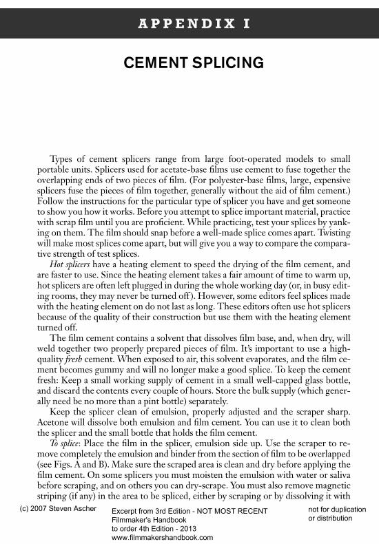
Types of cement splicers range from large foot-operated models to smallportable units. Splicers used for acetate-base films use cement to fuse together theoverlapping ends of two pieces of film. (For polyester-base films, large, expensivesplicers fuse the pieces of film together, generally without the aid of film cement.)Follow the instructions for the particular type of splicer you have and get someoneto show you how it works. Before you attempt to splice important material, practicewith scrap film until you are proficient. While practicing, test your splices by yank-ing on them. The film should snap before a well-made splice comes apart. Twistingwill make most splices come apart, but will give you a way to compare the compara-tive strength of test splices.
Hot splicers have a heating element to speed the drying of the film cement, andare faster to use. Since the heating element takes a fair amount of time to warm up,hot splicers are often left plugged in during the whole working day (or, in busy edit-ing rooms, they may never be turned off ). However, some editors feel splices madewith the heating element on do not last as long. These editors often use hot splicersbecause of the quality of their construction but use them with the heating elementturned off.
The film cement contains a solvent that dissolves film base, and, when dry, willweld together two properly prepared pieces of film. It’s important to use a high-quality fresh cement. When exposed to air, this solvent evaporates, and the film ce-ment becomes gummy and will no longer make a good splice. To keep the cementfresh: Keep a small working supply of cement in a small well-capped glass bottle,and discard the contents every couple of hours. Store the bulk supply (which gener-ally need be no more than a pint bottle) separately.
Keep the splicer clean of emulsion, properly adjusted and the scraper sharp.Acetone will dissolve both emulsion and film cement. You can use it to clean boththe splicer and the small bottle that holds the film cement.
To splice: Place the film in the splicer, emulsion side up. Use the scraper to re-move completely the emulsion and binder from the section of film to be overlapped(see Figs. A and B). Make sure the scraped area is clean and dry before applying thefilm cement. On some splicers you must moisten the emulsion with water or salivabefore scraping, and on others you can dry-scrape. You must also remove magneticstriping (if any) in the area to be spliced, either by scraping or by dissolving it with
dfha$$3.qxd 5/31/07 9:48 Page 789
(c) 2007 Steven Ascher Excerpt from 3rd Edition - NOT MOST RECENT Filmmaker's Handbook to order 4th Edition - 2013 www.filmmakershandbook.com
not for duplication or distribution
film cement and wiping it away. When scraping emulsion you must be careful notto scrape too deep and gouge the exposed base (see Fig. E).
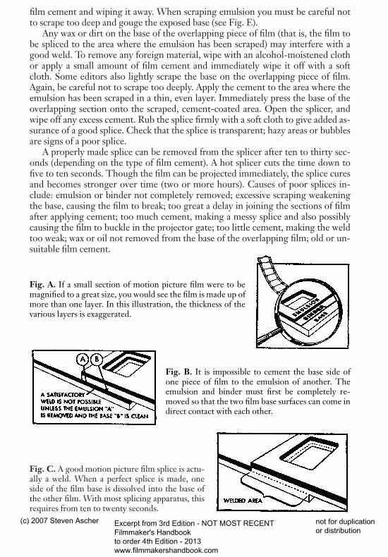
Any wax or dirt on the base of the overlapping piece of film (that is, the film tobe spliced to the area where the emulsion has been scraped) may interfere with agood weld. To remove any foreign material, wipe with an alcohol-moistened clothor apply a small amount of film cement and immediately wipe it off with a softcloth. Some editors also lightly scrape the base on the overlapping piece of film.Again, be careful not to scrape too deeply. Apply the cement to the area where theemulsion has been scraped in a thin, even layer. Immediately press the base of theoverlapping section onto the scraped, cement-coated area. Open the splicer, andwipe off any excess cement. Rub the splice firmly with a soft cloth to give added as-surance of a good splice. Check that the splice is transparent; hazy areas or bubblesare signs of a poor splice.
A properly made splice can be removed from the splicer after ten to thirty sec-onds (depending on the type of film cement). A hot splicer cuts the time down tofive to ten seconds. Though the film can be projected immediately, the splice curesand becomes stronger over time (two or more hours). Causes of poor splices in-clude: emulsion or binder not completely removed; excessive scraping weakeningthe base, causing the film to break; too great a delay in joining the sections of filmafter applying cement; too much cement, making a messy splice and also possiblycausing the film to buckle in the projector gate; too little cement, making the weldtoo weak; wax or oil not removed from the base of the overlapping film; old or un-suitable film cement.
Fig. C. A good motion picture film splice is actu-ally a weld. When a perfect splice is made, oneside of the film base is dissolved into the base ofthe other film. With most splicing apparatus, thisrequires from ten to twenty seconds.
790 APPENDIX I
Fig. A. If a small section of motion picture film were to bemagnified to a great size, you would see the film is made up ofmore than one layer. In this illustration, the thickness of thevarious layers is exaggerated.
Fig. B. It is impossible to cement the base side ofone piece of film to the emulsion of another. Theemulsion and binder must first be completely re-moved so that the two film base surfaces can come indirect contact with each other.
dfha$$3.qxd 5/31/07 9:48 Page 790
(c) 2007 Steven Ascher Excerpt from 3rd Edition - NOT MOST RECENT Filmmaker's Handbook to order 4th Edition - 2013 www.filmmakershandbook.com
not for duplication or distribution
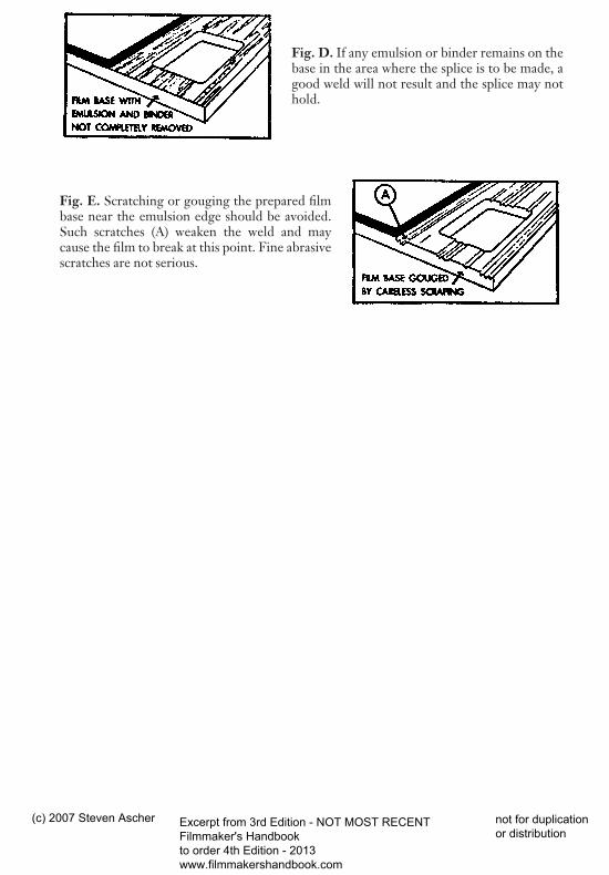
Fig. D. If any emulsion or binder remains on thebase in the area where the splice is to be made, agood weld will not result and the splice may nothold.
Fig. E. Scratching or gouging the prepared filmbase near the emulsion edge should be avoided.Such scratches (A) weaken the weld and maycause the film to break at this point. Fine abrasivescratches are not serious.
APPENDIX I 791
dfha$$3.qxd 5/31/07 9:48 Page 791
(c) 2007 Steven Ascher Excerpt from 3rd Edition - NOT MOST RECENT Filmmaker's Handbook to order 4th Edition - 2013 www.filmmakershandbook.com
not for duplication or distribution
A P P E N D I X J
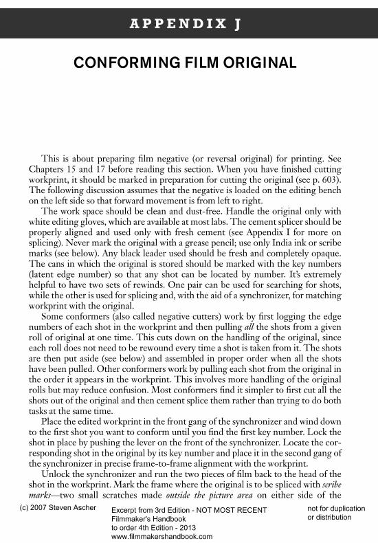
CONFORMING FILM ORIGINAL
This is about preparing film negative (or reversal original) for printing. SeeChapters 15 and 17 before reading this section. When you have finished cuttingworkprint, it should be marked in preparation for cutting the original (see p. 603).The following discussion assumes that the negative is loaded on the editing benchon the left side so that forward movement is from left to right.
The work space should be clean and dust-free. Handle the original only withwhite editing gloves, which are available at most labs. The cement splicer should beproperly aligned and used only with fresh cement (see Appendix I for more onsplicing). Never mark the original with a grease pencil; use only India ink or scribemarks (see below). Any black leader used should be fresh and completely opaque.The cans in which the original is stored should be marked with the key numbers(latent edge number) so that any shot can be located by number. It’s extremelyhelpful to have two sets of rewinds. One pair can be used for searching for shots,while the other is used for splicing and, with the aid of a synchronizer, for matchingworkprint with the original.
Some conformers (also called negative cutters) work by first logging the edgenumbers of each shot in the workprint and then pulling all the shots from a givenroll of original at one time. This cuts down on the handling of the original, sinceeach roll does not need to be rewound every time a shot is taken from it. The shotsare then put aside (see below) and assembled in proper order when all the shotshave been pulled. Other conformers work by pulling each shot from the original inthe order it appears in the workprint. This involves more handling of the originalrolls but may reduce confusion. Most conformers find it simpler to first cut all theshots out of the original and then cement splice them rather than trying to do bothtasks at the same time.
Place the edited workprint in the front gang of the synchronizer and wind downto the first shot you want to conform until you find the first key number. Lock theshot in place by pushing the lever on the front of the synchronizer. Locate the cor-responding shot in the original by its key number and place it in the second gang ofthe synchronizer in precise frame-to-frame alignment with the workprint.
Unlock the synchronizer and run the two pieces of film back to the head of theshot in the workprint. Mark the frame where the original is to be spliced with scribemarks—two small scratches made outside the picture area on either side of the
dfha$$3.qxd 5/31/07 9:48 Page 792
(c) 2007 Steven Ascher Excerpt from 3rd Edition - NOT MOST RECENT Filmmaker's Handbook to order 4th Edition - 2013 www.filmmakershandbook.com
not for duplication or distribution

sprocket hole where the splice is to be made. Roll both pieces of film to the rightslightly until the scribe marks are to the right of the synchronizer. Cut the originalwith scissors at least a half frame beyond the frame you just marked (which is to theright on most editing setups). This half frame is needed to make the cement splice.Some people routinely leave a frame and a half extra, which is fine as long as theframes aren’t needed for another shot.
Now wind down the workprint and original to the tail of the first workprintshot and scribe the original at the last sprocket hole of the shot. Roll the footageslightly to the left of the synchronizer and again cut the original a half frame longerthan the workprint shot.
Some conformers wind up each shot separately (either on a core or around it-self ) and wrap the last few winds in a piece of paper that identifies the shot by itskey number. Sometimes white leader is attached with a very small piece of tape tothe head and tail of each shot to protect it. The other widely practiced technique isto tape the shots in a continuous strand on a reel. This is feasible only if the shotshave been culled in the order they appear on the workprint. Some people feel this isa poor practice, since tape can damage the original and the gum may be hard to re-move. Only low-tack masking tape should be used on the original.
When cutting any shots to be used in a dissolve (which is possible only withA&B rolls unless you plan to use an optical printer), don’t forget to cut at the end ofthe dissolve mark on the workprint; that is, the shot should be cut one-half thelength of the dissolve longer than where the splice occurs in the workprint (thesplice is at the center of the dissolve). On the original, sometimes a small x is markedon either side of the sprocket hole at the center of the dissolve (see Fig. 17-5). Thisshould be done outside the picture area on both the A- and the B-rolls, as this helpsin aligning the rolls later.
When preparing A&B rolls, it’s advisable to have a synchronizer with at leastthree gangs. Begin by preparing the printing leaders as described in Chapter 17(see Fig. 17-8). Line up the printer start marks in the synchronizer. The SMPTEleader is usually spliced on the head of the B-roll immediately following the whiteprinting leader. Black leader is spliced opposite it on the A-roll and trimmed to thesame length (run both strands in the synchronizer to measure where to cut). Thefirst shot of the cut original film is then placed on the A-roll, with black leaderspliced on the B-roll opposite it, and so on.
Remember that fades are laid out differently for reversal films than they are fornegative films, while dissolves are laid out the same for each (see Chapter 17).
It is imperative that the emulsion of the black leader never be scraped during splicing, asthis will defeat the purpose of checkerboard printing—invisible splices. Scrape onlythe original film on the overlap you left when trimming each shot. The workprintshould be run in the third gang of the synchronizer so you can constantly checkthat you’ve correctly positioned shots and effects on the A&B rolls. After the rollsare spliced, they should once again be checked against the workprint for cutting er-rors. Don’t forget to do a cue sheet to instruct the lab concerning fades and dis-solves (see p. 673).
See Cinematography by Kris Malkiewicz (in Bibliography) for a more detaileddescription, with illustrations of how to conform original.
APPENDIX J 793
dfha$$3.qxd 5/31/07 9:48 Page 793
(c) 2007 Steven Ascher Excerpt from 3rd Edition - NOT MOST RECENT Filmmaker's Handbook to order 4th Edition - 2013 www.filmmakershandbook.com
not for duplication or distribution