Embed Size (px)
Citation preview

For the competent person
Installation and maintenance instructions
ecoTEC plusVU, VUW
GB, IE
Installation and maintenance instructions
Publisher/manufacturer
Vaillant GmbHBerghauser Str. 40 D-42859 RemscheidTel. +49 21 91 18‑0 Fax +49 21 91 18‑28 [email protected] www.vaillant.de

Contents
2 Installation and maintenance instructions ecoTEC plus 0020209591_00
Contents
1 Safety .................................................................... 4
1.1 Action-related warnings ......................................... 4
1.2 Intended use ......................................................... 4
1.3 General safety information .................................... 4
1.4 Regulations (directives, laws, standards) .............. 6
2 Notes on the documentation .............................. 8
2.1 Observing other applicable documents ................. 8
2.2 Storing documents................................................. 8
2.3 Applicability of the instructions .............................. 8
2.4 Benchmark............................................................. 8
2.5 Local regulations.................................................... 8
3 Product description............................................. 9
3.1 Product design....................................................... 9
3.2 Information on the identification plate.................... 9
3.3 Serial number ...................................................... 10
3.4 CE label ............................................................... 10
3.5 Energy Saving Trust Endorsed Products ............ 10
4 Installation.......................................................... 10
4.1 Unpacking the product......................................... 10
4.2 Checking the scope of delivery............................ 10
4.3 Transporting the product ..................................... 11
4.4 Dimensions .......................................................... 11
4.5 Minimum clearances............................................ 12
4.6 Clearance from combustible components ........... 12
4.7 Using the installation template............................. 12
4.8 Wall-mounting the product................................... 12
4.9 Removing the front casing................................... 13
4.10 Removing the side section .................................. 13
5 Installation.......................................................... 13
5.1 Installation requirements ..................................... 14
5.2 Installing the gas connection ............................... 14
5.3 Installing the hot and cold water connection........ 14
5.4 Connecting the domestic hot water cylinder........ 15
5.5 Connecting the heating flow and heatingreturn ................................................................... 15
5.6 Connecting the condensate drain pipework ........ 15
5.7 Installing the discharge pipe on the expansionrelief valve............................................................ 16
5.8 Flue gas installation............................................. 16
5.9 Electrical installation ............................................ 17
6 Operation............................................................ 18
6.1 Operating concept ............................................... 18
6.2 Calling up the installer level ................................. 18
6.3 Live Monitor (status codes) ................................. 19
6.4 Setting the hot water temperature ....................... 19
7 Start-up ............................................................... 19
7.1 Carrying out the initial start-up............................. 19
7.2 Switching the product on and off ......................... 19
7.3 Running the installation assistants ...................... 19
7.4 Restarting the installation assistants ................... 20
7.5 Test programmes................................................. 20
7.6 Performing a gas family check ............................ 20
7.7 Using check programmes.................................... 20
7.8 Checking and treating the heating water/fillingand supplementary water .................................... 21
7.9 Preventing low water pressure ............................ 22
7.10 Flushing the heating installation for the firsttime ("cold") ......................................................... 22
7.11 Filling the heating installation .............................. 22
7.12 Purging the heating installation ........................... 23
7.13 Filling and purging the hot water system ............. 23
7.14 Filling the condensate trap .................................. 23
7.15 Gas ratio setting................................................... 23
7.16 Checking function and leak-tightness.................. 26
7.17 Thoroughly flushing the heating installation("hot")................................................................... 26
8 Adapting the unit to the heatinginstallation.......................................................... 26
8.1 Burner anti-cycling time ....................................... 26
8.2 Setting the maintenance interval ......................... 27
8.3 Setting the pump output....................................... 27
8.4 Setting the bypass valve...................................... 28
8.5 Handing the product over to the operator............ 28
9 Troubleshooting ................................................ 29
9.1 Checking service messages................................ 29
9.2 Rectifying faults ................................................... 29
9.3 Calling up and clearing the fault memory ............ 29
9.4 Resetting parameters to factory settings ............. 29
9.5 Preparing the repair work .................................... 29
9.6 Replacing defective components......................... 29
9.7 Completing repair work........................................ 33
10 Inspection and maintenance ............................ 33
10.1 Function menu..................................................... 34
10.2 Electronics self-test.............................................. 34
10.3 Removing the compact thermal module .............. 34
10.4 Cleaning the heat exchanger............................... 35
10.5 Checking the burner ............................................ 35
10.6 Cleaning the condensate trap.............................. 35
10.7 Cleaning the filter in the cold water inlet.............. 35
10.8 Installing the compact thermal module ................ 36
10.9 Draining the product ............................................ 36
10.10 Checking the pre-charge pressure for theinternal expansion vessel .................................... 36
10.11 Completing inspection and maintenance work .... 36
11 Decommissioning.............................................. 36
11.1 Temporarily decommissioning the product.......... 36
11.2 Decommissioning the product ............................. 37
12 Recycling and disposal..................................... 37
13 Customer service............................................... 37
Appendix ............................................................................ 38
A Installer level – Overview .................................. 38
B Overview of diagnostics codes........................ 40
C Status codes – Overview .................................. 44
D Overview of fault codes .................................... 46

Contents
0020209591_00 ecoTEC plus Installation and maintenance instructions 3
E Connection diagrams........................................ 49
E.1 Connection diagram, product for heating modeonly, 12 - 35 kW................................................... 49
E.2 Connection diagram, product for heating modeonly, ≥ 37 kW....................................................... 51
E.3 Connection diagram, product with integratedhot water generation, 12 - 35 kW ........................ 53
E.4 Connection diagram, product with integratedhot water generation, ≥ 37 kW............................. 55
F Inspection and maintenance work –Overview............................................................. 56
G Commissioning Checklist................................. 58
H Opening of the flue pipe.................................... 62
H.1 Positioning of the opening of a fan-supportedflue gas pipe ........................................................ 62
I Text from BS 5440-1 on fan-supported fluegas pipes ............................................................ 63
J Opening of the flue pipe below eaves andbalconies ............................................................ 63
K Technical data.................................................... 63
Index ................................................................................... 69

1 Safety
4 Installation and maintenance instructions ecoTEC plus 0020209591_00
1 Safety
1.1 Action-related warnings
Classification of action-related warningsThe action-related warnings are classified inaccordance with the severity of the possibledanger using the following warning signs andsignal words:
Warning symbols and signal wordsDanger!Imminent danger to life or risk ofsevere personal injury
Danger!Risk of death from electric shock
Warning.Risk of minor personal injury
Caution.Risk of material or environmentaldamage
1.2 Intended use
There is a risk of injury or death to the user orothers, or of damage to the product and otherproperty in the event of improper use or usefor which it is not intended.
The product is intended as a heat generatorfor closed heating installations and for hotwater generation.
The products referred to in these instructionsmust only be installed and operated in con-junction with the flue pipe accessories listedin other applicable documents.
Exceptions: For C63 and B23P installationtypes, follow the specifications in these in-structions.
Intended use includes the following:
– observance of accompanying operating,installation and servicing instructions forthe product and any other system compon-ents
– installing and fitting the product in accord-ance with the product and system approval
– compliance with all inspection and main-tenance conditions listed in the instruc-tions.
Any other use that is not specified in theseinstructions, or use beyond that specified in
this document shall be considered improperuse. Any direct commercial or industrial useis also deemed to be improper.
Caution.
Improper use of any kind is prohibited.
1.3 General safety information
1.3.1 Risk caused by inadequatequalifications
Assembly and disassembly, installation, start-up, maintenance, repairs and decommission-ing must only be carried out by a compet-ent person who is sufficiently qualified to ob-serve all of the instructions that come with theproduct, to proceed in accordance with thecurrent state of the art, and to comply withall applicable directives, standards, laws andother regulations.
1.3.2 Risk of death from escaping gas
What to do if you smell gas in the building:
▶ Avoid rooms that smell of gas.▶ If possible, open doors and windows fully
and ensure adequate ventilation.▶ Do not use naked flames (e.g. lighters,
matches).▶ Do not smoke.▶ Do not use any electrical switches, mains
plugs, doorbells, telephones or other com-munication systems in the building.
▶ If it is safe to do so, close the emergencycontrol valve or the main isolator.
▶ If possible, close the gas isolator cock onthe product.
▶ Warn other occupants in the building byyelling or banging on doors or walls.
▶ Leave the building immediately and ensurethat others do not enter the building.
▶ Notify the gas supply company or NationalGrid Transco +44 (0) 800 111999 by tele-phone from outside of the building.
1.3.3 Risk of death from leaks if theproduct is installed below groundlevel!
Liquid gas is accumulating at floor level. If theproduct is installed below ground level, liquidgas may accumulate at floor level if there

Safety 1
0020209591_00 ecoTEC plus Installation and maintenance instructions 5
are any leaks. In this case, there is a risk ofexplosion.
▶ Make sure that liquid gas cannot escapefrom the product or the gas line under anycircumstance.
1.3.4 Risk of death due to blocked orleaking flue gas routes
Installation errors, damage, tampering, unau-thorised installation sites or similar can causeflue gas to escape and result in a risk of pois-oning.
What to do if you smell flue gas in the prop-erty:
▶ Open all accessible doors and windowsfully to provide ventilation.
▶ Switch off the product.▶ Check the flue gas routes in the product
and the flue gas diversions.
1.3.5 Risk of poisoning and burns causedby escaping hot flue gases
▶ Only operate the product if the air/flue pipehas been completely installed.
▶ With the exception of short periods fortesting purposes, only operate the productwhen the front casing is installed andclosed.
1.3.6 Risk of death due to explosive andflammable materials
▶ Do not use or store explosive or flammablematerials (e.g. petrol, paper, paint) in theinstallation room of the product.
1.3.7 Risk of death due to cabinet-typecasing
Cabinet-type casing can give rise to danger-ous situations when used on a product whichis operated with an open flue.
▶ Ensure that the product is supplied withsufficient combustion air.
1.3.8 Risk of poisoning caused byinsufficient supply of combustionair
Conditions: Open-flued operation
▶ Ensure that the air supply to the product'sinstallation room is permanently unobstruc-ted and sufficient in accordance with therelevant ventilation requirements.
1.3.9 Risk of death due to lack of safetydevices
The schematic drawings included in this doc-ument do not show all safety devices re-quired for correct installation.
▶ Install the necessary safety devices in thesystem.
▶ Observe the applicable national and inter-national laws, standards and guidelines.
1.3.10 Risk of death from electric shock
There is a risk of death from electric shock ifyou touch live components.
Before commencing work on the product:
▶ Disconnect the product from the powersupply by switching off all power supplies(electrical partition with a contact openingof at least 3 mm, e.g. fuse or line protec-tion switch).
▶ Secure against being switched back onagain.
▶ Wait for at least 3 minutes until the con-densers have discharged.
▶ Check that there is no voltage.
1.3.11 Risk of being burned or scalded byhot components
▶ Only carry out work on these componentsonce they have cooled down.
1.3.12 Risk of death from escaping fluegas
If you operate the product with an empty con-densate trap, flue gas may escape into theroom air.
▶ In order to operate the product, ensure thatthe condensate trap is always full.

1 Safety
6 Installation and maintenance instructions ecoTEC plus 0020209591_00
1.3.13 Risk of material damage caused byusing an unsuitable tool
▶ Use the correct tool to tighten or loosenscrew connections.
1.3.14 Risk of material damage caused byfrost
▶ Do not install the product in rooms proneto frost.
1.3.15 Risk of corrosion damage due tounsuitable combustion and roomair
Sprays, solvents, chlorinated cleaningagents, paint, adhesives, ammonia com-pounds, dust or similar substances may leadto corrosion on the product and in the air/fluepipe.
▶ Ensure that the supply of combustion air isalways free of fluorine, chlorine, sulphur,dust, etc.
▶ Ensure that no chemical substances arestored at the installation site.
▶ Ensure that the combustion air is notrouted through an old floor-standing oil-fired boiler chimney.
▶ If you are installing the product inhairdressing salons, painter's or joiner'sworkshops, cleaning businesses or similarlocations, choose a separate installationroom in which a combustion air supply isensured that is technically free of chemicalsubstances.
1.3.16 Risk of material damage caused byleak detection sprays and liquids
Leak detection sprays and liquids block thefilter of the mass flow sensor on the Venturi,and thus destroy the mass flow sensor.
▶ During repair work, do not apply any leakdetection sprays or liquids to the coveringcap on the filter of the Venturi.
1.3.17 Risk of damage to the flexible gaspipe
The corrugated gas pipe may become dam-aged if weight is placed on it.
▶ Do not suspend the compact thermal mod-ule on the flexible gas pipe, for exampleduring maintenance work.
1.4 Regulations (directives, laws,standards)
Installation and maintenance of the boilermust only be performed by a competent per-son with valid accreditation from the Healthand Safety Executive in accordance with the"Gas Safety (Installation and Use) Regula-tions 1998" (hereinafter abbreviated to "com-petent person" or "heating specialist com-pany"). The existing regulations, rules andguidelines must be observed when doing so.Any special requirements of Local Author-ities, gas undertakings or insurers must becomplied with. The competent person is alsoresponsible for inspection, maintenance andrepairs to the boiler, and for checking gasvolume setting and flue gas analysis.
Installers shall carryout a full site risk as-sessment and put into place all necessarysteps and procedures to comply with Healthand safety at work act and ensure safety ofthemselves and others with regard to manualhandling and working at height requirements.
During the appliance installation (and anysubsequent work, such as, the replacementof major parts ) it will be necessary to em-ploy caution. All installers and operatives in-volved from unloading the appliance until it isfully mounted on the wall in its final installedlocation must exercise full duty of care forthemselves and others with regard to safety.When lifting and handling this appliance, op-eratives should employ assistance. In certainsituations it may be necessary to use mech-anical handling aids. Take care to avoid triphazards, slippery or wet surfaces.
Employers and installers should referto the HSE web site for full advice andmanual handling assessment charts(MAC) tool.
In addition where no specific instructions aregiven then reference shall be made, but notrestricted to, all applicable and relevant Brit-ish Standards and codes of practice such asthe following:
– Gas Safety (Installation and Use) regula-tions.
– All current Building Regulations for Eng-land, Northern Ireland and Wales, (asamended). This includes Approved Codesof Practice and approved documents and

Safety 1
0020209591_00 ecoTEC plus Installation and maintenance instructions 7
guidance for building regulations. (A to Pand 7)
– The Building Standards, Scotland, andany requirements determined by the localauthorities within.
– The Health and safety at work act– COSHH Control of Substances Hazardous
to Health.– BS 7671 Requirements for electrical in-
stallations. IEE Wiring Regulations– The Electricity at Work Regulations.– The Water supply (water fittings) regula-
tions 1999.– Water bylaws 2000 (Scotland)– BS 5854 Code of practice for flues and flue
structures in buildings.– BS EN 12828 Design of water-based heat-
ing systems.– BS EN 806 Parts 1 - 5.– BS 8558 Guide to the design, installation,
testing and maintenance of services sup-plying water for domestic use within build-ings and their curtilages.
– BS 6880 Code of practice for low temper-ature heating systems with outputs above45 kW, Part 1, 2, and 3.
– BS 6891 Installation of low pressure gaspipe work of up to 35mm in domesticpremises.
– BS 4814 Specification for: Expansionvessels using an internal diaphragm, forsealed hot water and heating systems.
– BS 7074 Application, selection and install-ation of expansion vessels and ancillaryequipment for sealed water systems., Part1 and 2.
– BS 7593 Code of practice for treatment ofwater in domestic hot water central heatingsystems.
– BS 12831 Heating systems in buildings.Method for calculating design heat load.
– BS EN 13831 Closed expansion vesselswith built in diaphragm.
– EN 14336 Heating systems in buildings.Installation and commissioning of waterbased heating systems.
– BS 5440 – 1 Installation of flues and vent-ilation for gas appliances of rated input notexceeding 70kW*
– BS 5440 – 2 Flueing and ventilation for gasappliances of rated input not exceeding70kW** 1st 2nd and 3rd family gases.
– BS 5449 Forced circulation hot water sys-tems up to 45kW.
– BS EN 6798 Installation & maintenance ofgas fired hot water boilers of rated inputnot exceeding 70kW net.
– BS 5482 - Part 1 Domestic butane andpropane gas burning installations
Institute of Gas Engineers Publications:
– IGE/UP/1B (Edition 2) Tightness testingand direct purging of small natural gasinstallations.
– IGE/UP/ 7 (Edition 2) Gas in timber andlight steel framed buildings.
Additionally for gas boilers systems with out-puts greater than 70KW.
– BS 6644 Installation of gas boilersbetween 60 kW and 2 MW (2nd and 3rdfamily gases)
– BS 5449– IGE/UP/1 (Edition 2) Strength testing,
tightness testing and direct purging of in-dustrial and commercial gas installations.
– IGE/UP/1A (Edition 2) Strength testing,tightness testing and direct purging ofsmall, low pressure industrial and com-mercial natural gas installations.
– IGE/UP/10 Installation of gas appliancesin industrial and commercial premises.Part 1 Flued appliances.
– The installation must comply with the cur-rent version of the Clean Air Act.
– I.S. 813 Domestic Gas Installations– I.S. 820 Non Domestic Gas Installations– Building Control Act 2007– ETCI Regulations for installing electrical
systems

2 Notes on the documentation
8 Installation and maintenance instructions ecoTEC plus 0020209591_00
2 Notes on the documentation
2.1 Observing other applicable documents
▶ You must observe all the operating and installation in-structions included with the system components.
2.2 Storing documents
▶ Pass these instructions and all other applicable docu-ments on to the system operator.
2.3 Applicability of the instructions
These instructions apply only to:
Product article number
Article num-ber
Gas CouncilNumber
612 (VU GB 126/5‑5 A)ecoTEC plus
0010018531 41-044-78
615 (VU GB 156/5‑5 A)ecoTEC plus
0010018532 41-044-79
618 (VU GB 186/5‑5 A)ecoTEC plus
0010018533 41-044-80
618 (VU GB 186/5‑5 ALPG) ecoTEC plus
0010018534 41-044-81
624 (VU GB 246/5‑5 A)ecoTEC plus
0010018535 41-044-82
630 (VU GB 306/5‑5 A)ecoTEC plus
0010018536 41-044-83
630 (VU GB 306/5‑5 ALPG) ecoTEC plus
0010018537 41-044-84
637 (VU GB 376/5‑5 A)ecoTEC plus
0010018538 41-044-85
825 (VUW GB 256/5‑5)ecoTEC plus
0010018353 47-044-57
832 (VUW GB 326/5‑5)ecoTEC plus
0010018354 47-044-58
832 (VUW GB 326/5‑5LPG) ecoTEC plus
0010018355 47-044-59
835 (VUW GB 356/5‑5)ecoTEC plus
0010016540 47-044-53
838 (VUW GB 386/5‑5)ecoTEC plus
0010018356 47-044-60
2.4 Benchmark
Vaillant is a licensed member of the Benchmark Schemewhich aims to improve the standards of installation and com-missioning of domestic heating and hot water systems in theUK and to encourage regular servicing to optimise safety, ef-ficiency and performance.
Benchmark is managed and promoted by the Heating andHotwater Industry Council.
For more information visit www.centralheating.co.uk
2.5 Local regulations
Benchmark places responsibilities on both manufacturersand installers. The purpose is to ensure that customers areprovided with the correct equipment for their needs, that it isinstalled, commissioned and serviced in accordance with themanufacturer’s instructions by a competent person approvedat the time by the Health and Safety Executive and that itmeets the requirements of the appropriate Building Regu-lations. The Benchmark Checklist can be used to demon-strate compliance with Building Regulations and should beprovided to the customer for future reference.
Installers are required to carry out installation, commission-ing and servicing work in accordance with the BenchmarkCode of Practice which is available from the Heating andHotwater Industry Council who manage and promote theScheme.

Product description 3
0020209591_00 ecoTEC plus Installation and maintenance instructions 9
3 Product description
3.1 Product design
3.1.1 Functional elements, product for heatingmode only
7
8
9
10
13
11
12
14
15
18
5
4
1
2
3
16
17
6
1 Gas valve
2 Water pressure sensor
3 Venturi with mass flowsensor
4 Heat exchanger
5 Connection for the fluepipe
6 Flue gas measuringstub pipe
7 Expansion vessel
8 Air intake pipe
9 Compact thermal mod-ule
10 Ignition electrode
11 Fan
12 Automatic air vent
13 Pressure gauge
14 Internal pump
15 Bypass valve
16 Expansion relief valve
17 Diverter valve
18 Electronics box
3.1.2 Functional elements, product with hotwater generation
7
8
9
10
13
11
12
14
18
19
17
5
4
1
2
3
20
15
16
6
1 Gas valve
2 Water pressure sensor
3 Venturi with mass flowsensor
4 Heat exchanger
5 Connection for the fluepipe
6 Flue gas measuringstub pipe
7 Expansion vessel
8 Air intake pipe
9 Compact thermal mod-ule
10 Ignition electrode
11 Fan
12 Automatic air vent
13 Pressure gauge
14 Internal pump
15 Bypass valve
16 Expansion relief valve
17 Electronics box
18 Diverter valve
19 Impeller sensor (hotwater)
20 Secondary heat ex-changer
3.2 Information on the identification plate
The identification plate is mounted on the underside of theproduct in the factory.
Information on theidentification plate
Meaning
→ "CE label" section
Read the instructions.
VU… Vaillant gas-fired wall-hung boiler forheating
VUW… Vaillant gas-fired wall-hung boiler forheating and hot water generation

4 Installation
10 Installation and maintenance instructions ecoTEC plus 0020209591_00
Information on theidentification plate
Meaning
..6/5-5 Calorific value power/product generationequipment
ecoTEC plus Product description
2H, G20 – 20 mbar(2.0 kPa)
Gas group and gas connection pressureas set at the factory
ww/yyyy Date of manufacture: Week/year
Cat. Permissible gas categories
Types Approved gas-fired units
PMS Permissible total overpressure in heatingmode
PMW Permissible total overpressure during hotwater generation
Tmax. Max. flow temperature
ED 92/42 Current efficiency directive fulfilled with4* rating
V Hz Mains voltage and mains frequency
W Max. electrical power consumption
IP Level of protection
Heating mode
Hot water generation
P Nominal heat output range
Q Heat input range
D Nominal hot water draw-off rate
Proper disposal of the product
Bar code with serial number,
7th to 16th digit = product article number
Note
Make absolutely sure that the product is compat-ible with the gas group at the installation site.
3.3 Serial number
The serial number can be found on a plastic label behind thefront flap and on the identification plate.
Note
The serial number can also be shown on thedisplay of the product (→ Operating instructions).
3.4 CE label
The CE label shows that the products comply with the basicrequirements of the applicable directives as stated on theidentification plate.
The declaration of conformity can be viewed at the manufac-turer's site.
3.5 Energy Saving Trust Endorsed Products
Only the most energy efficient products can carry the‘Energy Saving Trust Endorsed Product’ brandmark makingit easy for consumers to choose products that have met strictenergy performance criteria.
Available for: Boilers, Heating controls and chemical inhib-itors, the Energy Saving Trust endorsed product brandmarkgives consumers confidence that a product will cost less torun, help lower energy bills and reduce carbon emissions.
About the Energy Saving Trust
Energy Saving Trust is an independent and impartial organ-isation that provides trusted energy saving advice to em-power millions of people to lead affordable, low energy life-styles. For more information visit energysavingtrust.org.uk
4 Installation
4.1 Unpacking the product
1. Remove the product from its box.
2. Remove the protective film from all parts of the product.
4.2 Checking the scope of delivery
▶ Check that the scope of delivery is complete and intact.
4.2.1 Scope of delivery
Applicability: Product with heating mode only
Num-ber
Description
1 Heat generator
1 Installation kit containing the following:
1 - Product retainer
1 - Expansion relief valve connector
1 - Gas connection pipe
2 - Heating flow/return connection pipe
3 - Service valve
3 - Bag with small parts
1 Lower cover
1 Installation template
1 Condensate drain hose
1 Enclosed documentation
4.2.2 Scope of delivery
Applicability: Product with integrated hot water generation
Num-ber
Description
1 Heat generator
1 Installation kit containing the following:
1 - Product retainer

Installation 4
0020209591_00 ecoTEC plus Installation and maintenance instructions 11
Num-ber
Description
1 - Expansion relief valve connector
1 - Gas connection pipe
2 - Heating flow/return connection pipe
2 - Cold water, hot water connection pipe
4 - Service valve
3 - Bag with small parts
1 Lower cover
1 Installation template
1 Condensate drain hose
1 Enclosed documentation
4.3 Transporting the product
4.3.1 General
▶ Hold the load as close as possible to your body. Do nottwist your body – instead, reposition your feet.
▶ If the unit is being lifted by two persons, ensure yourmovements are coordinated during lifting.
▶ Avoid bending your upper body – do not lean forwards orto the side.
▶ Wear appropriate cut-resistant and non-slip gloves toprotect yourself against sharp edges and maintain a safeand secure grip.
▶ If required, get somebody to assist you in this.
4.3.2 Unloading the box from the delivery van
▶ It is recommended that two people lift the unit together.
▶ Lift the box using the straps provided.
▶ Use safe lifting techniques – keep your back straight andbend your legs at the knee.
▶ Hold the load as close as possible to your body.
▶ If the unit is being lifted by two persons, ensure yourmovements are coordinated during lifting.
▶ If required, get somebody to assist you in this.
4.3.3 Transporting the box from the deliverypoint to the installation site – ground floor
▶ It is recommended that two people lift the unit together.
▶ Use safe lifting techniques – keep your back straight andbend your legs at the knee.
4.4 Dimensions
720
20
624
160
125
188
100 100
3535
440
A
B
180
125
2
1
3
5
7
9
8
4*
6*
6*4* 7
11 10
3 5 12
1 Flue pipe wall duct
2 Product holder
3 Heating flow (22 × 1.5diameter)
4 Hot water connection(15 × 1.5 diameter)
5 Gas connection(15 × 1.5 diameter)
6 Cold water connection(15 × 1.5 diameter)
7 Heating return (22 × 1.5diameter)
8 R1 tundish/condensatetrap connection
9 Flue pipe connection
10 Condensate dischargeconnection, 19 mmdiameter
11 Condensate trap

4 Installation
12 Installation and maintenance instructions ecoTEC plus 0020209591_00
12 Drain line/heating ex-pansion relief valveconnection, 15 mm dia-meter
* Only products withintegrated hot watergeneration
** Only products withheating mode only
Consult the installation template that is supplied to find thedimension A.
Installation depth, dimension B
612 (VU GB 126/5‑5 A) ecoTEC plus 338 mm
615 (VU GB 156/5‑5 A) ecoTEC plus 338 mm
618 (VU GB 186/5‑5 A) ecoTEC plus 338 mm
624 (VU GB 246/5‑5 A) ecoTEC plus 338 mm
630 (VU GB 306/5‑5 A) ecoTEC plus 372 mm
637 (VU GB 376/5‑5 A) ecoTEC plus 406 mm
825 (VUW GB 256/5‑5) ecoTEC plus 338 mm
832 (VUW GB 326/5‑5) ecoTEC plus 338 mm
835 (VUW GB 356/5‑5) ecoTEC plus 372 mm
838 (VUW GB 386/5‑5) ecoTEC plus 406 mm
4.5 Minimum clearances
BA
C C D
Minimum clearance
A 165 mm: Air/flue pipe, 60/100 mm diameter
275 mm: Air/flue pipe, 80/125 mm diameter
B 180 mm; optimum approx. 250 mm
C 5 mm; optimum approx. 50 mm
D 500 mm in front of the heat generator to enableeasy access for maintenance work (may beprovided by an opening door).
4.6 Clearance from combustible components
It is not necessary to maintain a clearance between theproduct and components made of combustible materials.
4.7 Using the installation template
▶ Use the installation template to ascertain the locations atwhich you need to drill holes and make breakthroughs.
4.8 Wall-mounting the product
1
1. Check whether the wall has sufficient load-bearing ca-pacity to bear the operational weight of the product.
2. Check if the supplied fixing material may be used forthe wall.
Conditions: The load-bearing capacity of the wall is sufficient, The fixing
material may be used for the wall
▶ Wall-mount the product as described.
▶ Install the product bracket (1) on the wall.
▶ Hang the product on the product bracket from aboveusing the suspension bracket.
Conditions: The fixing material may not be used for the wall
▶ Wall-mount the product as described using the permittedfixing material provided on-site.

Installation 5
0020209591_00 ecoTEC plus Installation and maintenance instructions 13
4.9 Removing the front casing
▶ Remove the front casing as shown in the illustration.
4.10 Removing the side section
2x
Caution.Risk of material damage caused by mech-anical deformation.
Removing both side sections may causemechanical distortion in the product, whichmay cause damage to the piping, for ex-ample, and potentially result in leaks.
▶ Always remove only one side section –never both side sections at the same time.
▶ Remove the side section as shown in the illustration.
5 Installation
Danger!Risk of scalding and/or risk of materialdamage due to incorrect installation lead-ing to escaping water.
Stresses in supply lines can cause leaks.
▶ Install the supply lines without tension.
Caution.Risk of material damage due to the gasleak-tightness test.
At a test pressure of >11 kPa (110 mbar), gasleak-tightness tests may cause damage tothe gas valve.
▶ If, during gas leak-tightness tests, youalso place the gas lines and the gas valvein the product under pressure, use a max.test pressure of 11 kPa (110 mbar).
▶ If you cannot limit the test pressure to11 kPa (110 mbar), close any gas isolatorcocks that are installed upstream from theproduct before you carry out the gas leak-tightness test.
▶ If, during gas leak-tightness tests, youhave closed the gas isolator cock that isinstalled upstream of the product, relievethe gas line pressure before you open thisgas isolator cock.
Caution.Risk of material damage due to corrosion.
If non-diffusion-tight plastic pipes are usedin the heating installation, this may causeair to enter the heating water and corrosionof the heat generation circuit and the heatgenerator.
▶ If using non-diffusion-tight plastic pipesin the heating installation, partition thesystem by installing an external heat ex-changer between the heat generator andthe heating installation.
Caution.Risk of material damage due to heat trans-fer during soldering.
▶ Do not solder the connection pieces ifthe connection pieces are screwed to theservice valves.

5 Installation
14 Installation and maintenance instructions ecoTEC plus 0020209591_00
5.1 Installation requirements
5.1.1 Information on liquid gas operation
In the as-delivered condition, the product is preset for opera-tion with the gas group indicated on the identification plate.
If you have a product that has been preset for operation withnatural gas, you must convert it to run on liquid gas. You willneed a conversion kit for this. The conversion procedure isdescribed in the manual supplied with the conversion kit.
5.1.2 Purging the liquid gas tank
If the liquid gas tank is not purged properly, this may result inignition problems.
▶ Ensure that the liquid gas tank has been purged properlybefore installing the product.
▶ If required, contact the filler or the liquid gas supplier.
5.1.3 Using the correct type of liquid gas
Using the incorrect type of liquid gas may cause fault shut-downs in the product. Ignition and combustion noise mayoccur in the product.
▶ Only use the gases listed on the identification plate.
5.1.4 Required preliminary work
1. Install a stop cock in the gas line.
2. Make sure that the existing gas meter is capable ofpassing the rate of gas supply required.
3. Check that the volumetric capacity of the expansionvessel is sufficient for the system volume.
Conditions: The volume of the installed expansion vessel is insufficient
▶ Install an additional expansion vessel, connected asclose to the product as possible, in the heating return.
Conditions: External expansion vessel installed
▶ Install a non-return valve in the product outlet (heatingflow) or decommission the internal expansion vesselin order to prevent the warm start function from beingincreasingly activated due to backflow.
4. Install a tundish with siphon for the condensate dis-charge and the exhaust pipe on the expansion reliefvalve. Lay as short a drain line as possible, at a down-ward gradient away from the tundish.
5. Insulate bare pipes exposed to environmental influ-ences to protect them from frost using suitable insu-lating material.
5.2 Installing the gas connection
1. Install the gas line in accordance with the recognisedrules of technology.
2. Connect the product to the gas line as shown in ac-cordance with the recognised rules of good engineeringpractice.
3. Remove the residues from the gas line by blowingthrough the gas line beforehand.
4. Purge the gas line before start-up.
5. Check the gas line for leak-tightness.
5.3 Installing the hot and cold water connection
Applicability: Product with integrated hot water generation
1. Make the water connections as shown in accordancewith the relevant standards.
2. Ensure correct water pressure and flow requirementsand that any expansion can be accommodated with thecold supply pipe work.

Installation 5
0020209591_00 ecoTEC plus Installation and maintenance instructions 15
5.4 Connecting the domestic hot water cylinder
Applicability: Product with heating mode only
▶ When connecting the domestic hot water cylinder, followthe Installation instructions for the domestic hot watercylinder.
5.5 Connecting the heating flow and heatingreturn
▶ Make the heating connections as shown in accordancewith the relevant standards.
5.6 Connecting the condensate drain pipework
Danger!Risk of death from escaping flue gases!
The condensate drain pipework for the si-phon must not be connected tightly to waste-water piping because, otherwise, the internalcondensate trap may be drained fully and fluegas may escape.
▶ Do not connect the condensate drainpipework tightly to the waste-water pip-ing.
SoakawayGulleyInternalstackpipe
Internaldischarge system
min.180
11
2
3
The product is equipped with a condensate trap (2). (Thefilling height is 145 mm). The condensate trap collects thecondensate that has formed in a vessel with a capacity ofapproximately 200 ml, and intermittently releases the con-tents into the discharge pipe. This minimises the risk of thedischarge pipe freezing.
▶ Connect the condensate discharge (1) to condensatedrain pipework (3) which has a minimum internal dia-meter of 19 mm (22 mm outside diameter for all externalpipes) and is made from an acid-resistant material (e.g.plastic overflow pipe).
– The condensate discharge pipework must havea continuous fall (45 mm per metre) and shouldwhenever possible terminate at a suitable dischargepoint within the heated envelope of the buildingthat will remain frost free under long periods of lowexternal temperatures.
▶ During installation remove all burs from inside of cut pipework and avoid excessive adhesive which may trap smallpockets of water close to the pipe wall which can freezeand build into a larger ice plug.
▶ As with other pipe work insulate the condensate dis-charge pipe to minimise any risk of freezing and bewarewhen crossing cavities that the fall is maintained and thepipe sleeved.
▶ Ensure that the condensate drain pipework terminates ina suitable location. Further information can be obtainedfrom BS 6798 Specification for installation of gas–firedboilers of rated input not exceeding 70 kW net.
▶ Leave an installation space of at least 180 mm beneaththe condensate trap.

5 Installation
16 Installation and maintenance instructions ecoTEC plus 0020209591_00
5.7 Installing the discharge pipe on theexpansion relief valve
1. Install the discharge pipe for the expansion relief valveso that it does not interfere with the removal and fittingof the lower section of the condensate trap.
2. Install the discharge pipe as shown (do not shorten).
3. Make sure that the end of the pipe is visible.
4. Ensure that discharged water or steam cannot causeinjury to persons or damage to electronic components.
5. Ensure the discharge pipe work is installed, routed andterminated correctly to minimise the risk of freezing up.
5.8 Flue gas installation
5.8.1 Installing and connecting the flue pipe
1. You can find out which flue pipes may be used by con-sulting the enclosed flue pipe installation manual.
2. Observe the information on positioning the openingfor the flue pipe. This information can be found in theappendix.
Conditions: Installation in damp rooms
▶ You must connect the product to a room-sealed air/fluegas installation. The combustion air must not be takenfrom the installation site.
Caution.Risk of poisoning due to escaping fluegas.
Mineral-oil-based greases can damage theseals.
▶ Instead of grease, use only water or com-mercially available soft soap to aid install-ation.
3. Install the flue pipe using the installation manual.
5.8.2 Replacing the connection piece for theair/flue pipe as required
1. Replace the connection piece for the air/flue pipe asrequired. The product-specific standard equipment islisted under Technical data.
2. Remove the connection piece for the air/flue pipe.(→ Page 16)
3. Alternatives 1 / 2▶ If required, install the connection piece for the
air/flue pipe, 80/125 mm diameter. (→ Page 16)
3. Alternatives 2 / 2▶ If required, install the connection piece with
offset for the air/flue pipe, 60/100 mm diameter.(→ Page 16)
5.8.2.1 Removing the connection piece for theair/flue pipe
1.2.
3.
1. Insert a screwdriver into the slot between the measuringstub pipes.
2. Press the screwdriver carefully down (1.).
3. Turn the connection piece anticlockwise (2.) as far as itwill go and then remove it by pulling it upwards (3.).
5.8.2.2 Installing the connection piece for theair/flue pipe, 80/125 mm diameter
1. Remove the connection piece for the air/flue pipe.(→ Page 16)
2. Insert the alternative connection piece. In doing so, payattention to the latching lugs.
3. Turn the connection piece clockwise until it clicks intoposition.
5.8.2.3 Installing the connection piece with offsetfor the air/flue pipe, 60/100 mm diameter
1. Remove the connection piece for the air/flue pipe.(→ Page 16)

Installation 5
0020209591_00 ecoTEC plus Installation and maintenance instructions 17
65 mm
1
2. Insert the alternative connection piece with offset to-wards the front.
3. Use two screws (1) to secure the connection piece tothe product.
5.9 Electrical installation
The electrical installation must only be carried out by a quali-fied electrician.
Danger!Risk of death from electric shock!
Mains connection terminals L and N remainlive even if the on/off switch is turned off:
▶ Switch off the power supply.▶ Secure the power supply against being
switched on again.
5.9.1 Opening the electronics box
▶ Open the electronics box as shown in the illustration.
5.9.2 Carrying out the wiring
Caution.Risk of material damage caused by incor-rect installation.
Mains voltage at incorrect terminals and plugterminals may destroy the electronics.
▶ Do not connect any mains voltage to theeBUS terminals (+/-).
▶ Only connect the mains connection cableto the terminals marked for the purpose.
1. Route the supply lines of the components to be connec-ted through the cable duct provided on the underside ofthe product on the left.
2. Use strain reliefs.
3. Shorten the supply lines as necessary.
30 mm max.
4. To prevent short circuits if a strand accidentally comesloose, only strip the outer sheathing of flexible lines to amaximum of 30 mm.
5. Ensure the inner conductor insulation is not damagedwhen stripping the outer sheathing.
6. Only strip inner conductors just enough to establishgood, sound connections.
7. To avoid short circuits resulting from loose individualwires, fit conductor end sleeves on the stripped ends ofthe conductors.
8. Screw the respective plug to the supply line.
9. Check whether all conductors are sitting mechanicallysecurely in the terminals of the plug. Remedy this ifnecessary.
10. Plug the plug into the associated PCB slot; see theconnection diagram in the appendix.
5.9.3 Establishing the power supply
Caution.Risk of material damage due to high con-nected voltage.
At mains voltages greater than 253 V, elec-tronic components may be damaged.
▶ Make sure that the rated voltage of themains is 230 V.
1. Make sure that the nominal mains voltage is 230 V.
2. Provide one common electricity supply for the boilerand for the corresponding controller:
– Power supply: Single-phase, 230 V, 50 Hz
– Fuse protection: ≤ 3 A
3. Open the electronics box. (→ Page 17)
4. Connect the product using a fixed connection and apartition with a contact opening of at least 3 mm (e.g.fuses or power switches).
5. Route a three-core mains connection cable that com-plies with the relevant standards through the cable ductand into the product.
– Mains connection line: Flexible line
6. Carry out the wiring. (→ Page 17)
7. Remove the supplied plug from the bracket in the elec-tronics box and screw the plug onto the mains connec-tion cable.
8. Close the electronics box.
9. Make sure that access to the mains connection is al-ways available and is not covered or blocked.

6 Operation
18 Installation and maintenance instructions ecoTEC plus 0020209591_00
5.9.4 Installing the product in a moistenvironment
Danger!Risk of death from electric shock!
If you install the product in a room with highlevels of moisture, e.g. a bathroom, observethe nationally recognised technical standardsfor electrical installations. If you use the fact-ory-installed connection cable, if installed,with an earthed plug, there is a risk of deathfrom electric shock.
▶ Never use the factory-installed connectioncable with earthed plug when installing theproduct in a moist environment.
▶ Connect the product using a fixed connec-tion and a partition with a contact open-ing of at least 3 mm (e.g. fuses or powerswitches).
▶ Use a flexible line for the mains connec-tion line, which is routed through the cableduct into the product.
1. Open the electronics box. (→ Page 17)
2. Detach the plug from the PCB slot for the mains con-nection (X1).
3. Unscrew the plug of the factory-installed mains connec-tion cable, if installed.
4. Instead of the factory-installed mains connection cable,if installed, use a suitable three-core mains connectioncable which complies with the relevant standards.
5. Carry out the wiring. (→ Page 17)
6. Close the electronics box.
7. Observe the flue-gas connection that is required on aroom-sealed air/flue gas installation. (→ Page 16)
5.9.5 Connecting controllers to the electronicsystem
1. Install the controller if necessary.
2. Open the electronics box. (→ Page 17)
3. Carry out the wiring. (→ Page 17)
4. Observe the connection diagram in the appendix.
Conditions: Connecting a weather compensator or a room temperature
controller via eBUS
▶ Connect the controller to the eBUS connection.
▶ Bridge the 24 V = RT connection (X100 or X106), if thereis not already a bridge.
Conditions: Connecting a low-voltage controller (24 V)
▶ Remove the bridge and connect the controller to the24 V = RT connection (X100 or X106).
Conditions: Connecting a limit thermostat for underfloor heating
▶ Remove the bridge and connect the limit thermostat tothe Burner off connection.
5. Close the electronics box.
6. For multi-circuit controllers, change D.018 from Eco (in-termittently operating pump) to Comfort (continuouslyoperating pump). (→ Page 26)
5.9.6 Connecting additional components
You can actuate an additional component with the aid of theauxiliary relay that is installed, and you can actuate two othercomponents with the multi-functional module.
5.9.6.1 Using the auxiliary relay
1. Connect an additional component directly to the integ-rated auxiliary relay using the grey plug on the PCB.
2. Carry out the wiring.
3. To start up the connected component, select the com-ponent in diagnostics code D.026. (→ Page 26)
5.9.6.2 Using the VR 40 ("2 in 7" multi-functionalmodule)
1. Install the components in accordance with the respect-ive instructions.
Conditions: Components connected to relay 1
▶ Activate D.027. (→ Page 26)
Conditions: Components connected to relay 2
▶ Activate D.028. (→ Page 26)
5.9.7 Actuating the circulation pump accordingto requirements
1. Carry out the wiring.
2. Connect the supply line for the external button usingterminals 1 (0) and 6 (functional drawing) on the X41edge connector, which is supplied with the controller.
3. Plug the edge connector into the PCB slot X41.
6 Operation
6.1 Operating concept
The operating concept and the read-off and setting facilitiesof the operator level are described in the operating instruc-tions.
An overview of the reading and setting options for the in-staller level is included in the table in the appendix.
Installer level – Overview (→ Page 38)
6.2 Calling up the installer level
1. Only call up the installer level if you are a competentperson.
2. Navigate to Menu → Installer level and confirm bypressing .
3. Set the value 17 (code) and confirm by pressing .

Start-up 7
0020209591_00 ecoTEC plus Installation and maintenance instructions 19
6.3 Live Monitor (status codes)
Menu → Live Monitor
Status codes in the display provide information on the pro-duct's current operating status.
Status codes – Overview (→ Page 44)
6.4 Setting the hot water temperature
Applicability: Product with integrated hot water generation
Conditions: Water hardness: > 3.57 mol/m³
Danger!Risk of death from Legionella.Legionella multiply at temperatures below60 °C.▶ Ensure that the operator is familiar with
all of the Anti-legionella measures in or-der to comply with the applicable regula-tions regarding legionella prevention.
▶ Set the hot water temperature to a maximum of 50 °C.
7 Start-up
7.1 Carrying out the initial start-up
Initial start-up must be carried out by a customer servicetechnician or an authorised competent person using thecommissioning checklist. The commissioning checklist in theappendix (→ Page 58) of the installation instructions must befilled in and stored carefully along with the unit's documenta-tion.
▶ Carry out the start-up procedure using the commissioningchecklist in the appendix.
▶ Fill in and sign the commissioning checklist.
7.2 Switching the product on and off
▶ Press the on/off button on the product.
◁ The basic display appears on the display.
7.3 Running the installation assistants
The installation assistant is displayed whenever the productis switched on until it has been successfully completed.It provides direct access to the most important checkprogrammes and configuration settings for starting up theproduct.
To recheck and reset the most important system parameters,call up the Appliance config..
Menu → Installer level Appliance config.
The settings options for more complex systems can be foundin the Diagnostics menu.
Menu → Installer level Diagnostics menu
▶ Press to confirm installation assistant start-up.
◁ All heating and hot water requests are blocked whilstthe installation assistant is active.
Note
If you do not confirm the launch of the install-ation assistant within 10 seconds of switchingthe system on, the basic display reappears.
▶ To access the next point, confirm by pressing in eachcase.
7.3.1 Language
▶ Set the required language.
▶ To confirm the set language and to avoid unintentionallychanging it, press to confirm this twice.
If you have unintentionally set a language that you do notunderstand, proceed as follows to change it:
▶ Press and hold and at the same time.
▶ Also briefly press .
▶ Press and hold and until the display shows thelanguage setting option.
▶ Select the required language.
▶ Press twice to confirm this change.
7.3.2 Filling mode
Filling mode (check programme P.06) is activated automatic-ally in the installation assistant for as long as the filling modeappears on the display.
7.3.3 Purging
1. Unlike in the Check programs menu, to purge the sys-tem, start up the check programme P.00 by pressingor .
2. If you need to change the circuit that is being purged,press .
7.3.4 Target feed temperature, hot watertemperature, Comfort mode
1. To set the target flow temperature, hot water temperat-ure and Comfort mode, use and .
2. Press to confirm this setting.
7.3.5 Heating partial load
The heating partial load of the product is set to Auto at thefactory. The product independently determines the optimumheating output depending on the current heat demand ofthe system. You can retroactively change the setting in theDiagnostics menu under D.000.
7.3.6 Auxiliary relay and multi-functional module
1. If you have connected additional components to theproduct, assign these components to the individual re-lays.
2. In each case, confirm by pressing .
Note
This setting can be retroactively changed inthe Diagnostics menu using D.026, D.027and D.028.

7 Start-up
20 Installation and maintenance instructions ecoTEC plus 0020209591_00
7.3.7 Contact data
▶ If required, store your telephone number in the Appli-ance config. (max. 16 digits/no blank spaces). The oper-ator can view the telephone number.
7.3.8 Ending the installation assistant
▶ Once you have run through the installation assistant suc-cessfully, confirm by pressing .
◁ The installation assistant will close and will not launchagain when the product is next switched on.
7.4 Restarting the installation assistants
Menu → Installer level → Start inst. assistant
You can restart the installation assistant at any time by call-ing it up in the menu.
7.5 Test programmes
Menu → Installer level Test programs
As well as the installation assistants, you can also call upthe following test programmes for start-up, service andtroubleshooting.
– Check programs
– Function menu
– Electronics self-test
7.6 Performing a gas family check
Danger!Risk of poisoning!
Inadequate combustion quality (CO), indic-ated by F.92/93, leads to an increased risk ofpoisoning.
▶ Make sure that the fault is completelyeliminated before starting up the productfor continuous operation.
Menu → Installer level → Test programs → Gas familycheck
The gas family check checks the product setting with regardto combustion quality.
Note
If additional condensing units are connected to thesame flue gas pipe in the heating installation, en-sure that none of these condensing units are inoperation or start operating throughout the entiretest programme, so that the test result is not dis-torted.
▶ Perform the gas family check as part of routine productmaintenance work, after replacing components, carryingout work on the gas route and following gas conversion.
Result Meaning Measure
F.92 See the table offault codes in theappendix
See the table of faultcodes in the appendix
"Successful" Combustionquality is good.
Unit configur-ation matchesthe specified gasgroup.
None
"Warning" Combustionquality inad-equate.
CO₂ content isincorrect.
Start check programmeP.01 and adjust theCO₂ content with theadjusting screw in theVenturi.
If the correct CO₂ con-tent cannot be set:Check that the gas re-strictor is correct (yellow:G20 natural gas, blue:G25 natural gas, grey:Liquid gas) and undam-aged.
Repeat the gas familycheck.
F.93 See the table offault codes in theappendix
See the table of faultcodes in the appendix
Note
It is not possible to perform CO₂ measure-ments during the gas family check.
7.7 Using check programmes
Menu → Installer level → Test programs → Check pro-grams
Display Meaning
P.00 Purging check programme:
The internal pump is cyclically actuated.
The heating circuit and the hot water circuit arepurged via the automatic air vent (the cap of theautomatic air vent must be released).
1 x : Start heating circuit purging
2 x ( ): Start hot water circuit purging
3 x ( ): Restart heating circuit purging
1 x (Cancel): End purge programme
Note
The purge programme runs for 7.5 min per circuitand then terminates.
Purging the heating circuit:
Diverter valve in heating position, actuation of in-ternal pump for 9 cycles: 30 sec. on, 20 sec. off.Display: Active heating circuit.
Purging the hot water circuit:
After the above-mentioned cycles have run or theright-hand selection button has been pressed again:Diverter valve in the hot water position, actuationof the internal pump as above. Display: Active hotwater circuit.

Start-up 7
0020209591_00 ecoTEC plus Installation and maintenance instructions 21
Display Meaning
P.01 Maximum load check programme:
After successful ignition, the product is operated atmaximum heat input.
P.02 Minimum load check programme:
After successful ignition, the product is operated atminimum heat input.
P.06 Filling mode check programme:
The diverter valve is moved to the mid-position. Theburner and pump are switched off (to fill or drain theproduct).
7.8 Checking and treating the heatingwater/filling and supplementary water
Caution.Risk of material damage due to poor-qual-ity heating water
▶ Ensure that the heating water is of suffi-cient quality.
▶ Before filling or topping up the system, check the qualityof the heating water.
Checking the quality of the heating water▶ Remove a little water from the heating circuit.
▶ Check the appearance of the heating water.
▶ If you ascertain that it contains sedimentary materials,you must desludge the system.
▶ Use a magnetic rod to check whether it contains mag-netite (iron oxide).
▶ If you ascertain that it contains magnetite, clean the sys-tem and apply suitable corrosion-protection measures, orfit a magnet filter.
▶ Check the pH value of the removed water at 25 °C.
▶ If the value is below 8.2 or above 10.0, clean the systemand treat the heating water.
▶ Ensure that oxygen cannot get into the heating water.(→ Page 26)
Checking the filling and supplementary water▶ Before filling the system, measure the hardness of the
filling and supplementary water.
Treating the filling and supplementary water▶ Observe all applicable national regulations and technical
standards when treating the filling and supplementarywater.
Provided the national regulations and technical standardsdo not stipulate more stringent requirements, the followingapplies:
You must treat the heating water in the following cases:
– If the entire filling and supplementary water quantity dur-ing the operating life of the system exceeds three timesthe nominal volume of the heating installation, or
– If the guideline values listed in the following table are notmet, or
– If the pH value of the heating water is less than 8.2 ormore than 10.0.
Totalheatingoutput
Water hardness at specific system volume1)
≤ 20 l/kW> 20 l/kW≤ 50 l/kW
> 50 l/kW
kWppm
CaCO₃ mol/m³ppm
CaCO₃ mol/m³ppm
CaCO₃ mol/m³
< 50 < 300 < 3 200 2 2 0.02
> 50to ≤ 200
200 2 150 1.5 2 0.02
> 200to ≤ 600
150 1.5 2 0.02 2 0.02
> 600 2 0.02 2 0.02 2 0.02
1) Nominal capacity in litres/heating output; in the case of multi-boiler systems, the smallest single heating output is to be used.
Caution.Risk of material damage if the heatingwater is treated with unsuitable additives.
Unsuitable additives may cause changes inthe components, noises in heating mode andpossibly subsequent damage.
▶ Do not use any unsuitable frost and cor-rosion protection agents, biocides or seal-ants.
No incompatibility with our products has been detected todate with proper use of the following additives.
▶ When using additives, follow the manufacturer's instruc-tions without exception.
We accept no liability for the compatibility of any additive orits effectiveness in the rest of the heating system.
Additives for cleaning measures (subsequentflushing required)– Fernox F3
– Sentinel X 300
– Sentinel X 400
Additives intended to remain permanently in thesystem– Fernox F1
– Fernox F2
– Sentinel X 100
– Sentinel X 200
Additives for frost protection intended to remainpermanently in the system– Fernox Antifreeze Alphi 11
– Sentinel X 500
▶ If you have used the above-mentioned additives, informthe operator about the measures required.
▶ Inform the operator about the measures required for frostprotection.

7 Start-up
22 Installation and maintenance instructions ecoTEC plus 0020209591_00
7.9 Preventing low water pressure
To ensure that the heating installation operates smoothly,the indicator on the pressure gauge must point to the upperhalf of the grey area or to the middle of the bar graph displayin the display (marked by the dashed limit values) when theheating installation is cold. This corresponds to a filling pres-sure of between 0.1 MPa and 0.2 MPa (1.0 bar and 2.0 bar).
If the heating installation extends over several storeys,higher filling pressures may be required to avoid air enteringthe heating installation.
If the filling pressure falls below 0.08 MPa (0.8 bar), theproduct indicates low pressure by displaying a flashingpressure value. If the filling pressure falls below 0.05 MPa(0.5 bar), the product switches off. The display shows F.22.
▶ Top up the heating water to start the product up again.
The pressure value flashes in the display until a pressure of0.11 MPa (1.1 bar) or higher has been reached.
7.10 Flushing the heating installation for the firsttime ("cold")
Note
The complete heating system must be flushedat least twice: Once with cold water and oncewith hot water in accordance with the followinginstructions.
1. Check whether all thermostatic radiator valves and bothservice valves on the product are open.
2. Connect a hose to the drain valve that is located at thelowest position in the heating system.
3. Open the radiator valves and the drain valves so thatthe water can drain quickly. Start at the next point in thesystem and open the purging valves on the radiators sothat the contaminated water can completely drain.
4. Close the drain cocks.
5. Refill the heating system with water.
6. Check that the expansion relief valve of the heatingsystem is functioning correctly by turning the handleon the valve.
7. Check the pressure in the heating system and top upwith water if necessary.
8. Close the filling valve and the cold water valve.
7.11 Filling the heating installation
1
1. Flush the heating installation through.
2. Undo the cap of the automatic air vent (1) by one to tworotations and leave it open, as the product purges itselfvia the automatic air vent even in continuous mode.
3. Select the check programme P.06.
◁ The diverter valve moves to the mid-position, thepumps do not run and the product does not switchto heating mode.
4. Observe the information on treating heating water.(→ Page 21)
5. Check all connections and the entire system for leaks.
Conditions: Applies to: Products with integrated hot water generation
3
12
4
▶ Open all radiator valves (thermostatic radiator valves) ofthe heating installation.
▶ Fit the double non-return valve (1) of the filling line tothe cold water stop valve and secure the valve with thespring clip (2).
▶ To fill, first open the stop valve (3).
▶ Open the stop valve (4) so that the water flows into theheating system. Fill the heating system.
▶ Purge the lowest radiator until water flows out of thepurging valve without bubbles.
▶ Purge all other radiators until the entire heating systemhas been filled with water.
▶ Close all purging valves.
▶ Monitor the rising filling pressure in the heating installa-tion.
▶ Fill with water until the required filling pressure isreached.
▶ After filling, close both stop valves and disconnect thefilling device by removing the double non-return valvefrom the cold water stop valve.
Note
Both stop valves must be closed while theheating system is operating and the filling linemust be removed from the double non-returnvalve again.
Conditions: Applies to: Products with heating mode only
▶ Connect the filling and drainage tap in the heating in-stallation to a heating water supply, if possible with the

Start-up 7
0020209591_00 ecoTEC plus Installation and maintenance instructions 23
cold water valve, in accordance with the relevant stand-ards.
▶ Open the heating water supply.
▶ Open all radiator valves (thermostatic radiator valves) ofthe heating installation.
▶ If necessary, check that both service valves on theproduct are open.
▶ Slowly open the filling and drainage tap so that the waterflows into the heating system.
▶ Purge the lowest radiator until water flows out of thepurging valve without bubbles.
▶ Purge all other radiators until the entire heating systemhas been filled with water.
▶ Close all purging valves.
▶ Monitor the rising filling pressure in the heating installa-tion.
▶ Fill with water until the required filling pressure isreached.
▶ Close the filling and drainage tap and the cold watervalve.
7.12 Purging the heating installation
1. Select the check programme P.00.
◁ The product does not start up, the internal pumpoperates intermittently and purges either the heatingcircuit or the hot water circuit.
◁ The display shows the filling pressure of the heatinginstallation.
2. Make sure that the filling pressure of the heating install-ation does not fall below the minimum filling pressure.
– ≥ 0.08 MPa ( ≥ 0.80 bar)
◁ At the end of the filling procedure, the filling pres-sure of the heating installation should be at least0.02 MPa (0.2 bar) above the counter-pressureof the expansion vessel ("Exp") (PInstallation ≥ PExp +0.02 MPa (0.2 bar)).
3. If there is still too much air in the heating installation atthe end of the check programme P.00, repeat the checkprogramme.
7.13 Filling and purging the hot water system
Applicability: Product with integrated hot water generation
1. Open the cold water stop valve on the product.
2. Fill the hot water system by opening all the hot waterdraw-off valves until water escapes.
7.14 Filling the condensate trap
1
1. Remove the lower section from the condensate trap (1).
2. Fill the lower section with water up to 10 mm below theupper edge.
3. Attach the lower section to the condensate trap.
7.15 Gas ratio setting
7.15.1 Checking the factory-set gas ratio setting
Caution.Risk of material damage caused by mak-ing unauthorised settings.
▶ Never modify the factory setting of the gaspressure regulator of the gas valve.
▶ Before you start up the product, compare the gas groupinformation on the identification plate with the gas groupavailable at the installation site.
Conditions: The product design is not compatible with the local gas group
Only Vaillant Service Solutions may perform a gas conver-sion.
If a gas conversion to liquid gas has been carried out, thesmallest possible partial load is higher than is shown on thedisplay. The correct values can be found in the Technicaldata in the appendix.
▶ Call Vaillant Service Solutions (0330 1003 143).
▶ Do not start up the product.
Conditions: The product design is compatible with the local gas group
▶ Proceed as described below.

7 Start-up
24 Installation and maintenance instructions ecoTEC plus 0020209591_00
7.15.2 Checking the leak-tightness of the flue gassystem and for flue gas recirculation
1. Check the integrity of the flue gas system.
2. If the flue gas system is longer than 2 m, we urgentlyrecommend that you test the system for flue gas recir-culation as described below.
3. Use the air analysis point to check for flue gas recircula-tion.
4. Use the flue gas measuring instrument.
5. If you discover CO or CO2 in the fresh air, search for aleak in the flue gas system or for the flue gas recircula-tion.
6. Eliminate the damage.
7. Repeat the above-mentioned test to determine if thefresh air contains CO or CO2.
8. If you cannot eliminate the damage, you must not startup the boiler.
7.15.3 Checking the gas flow rate
The boiler is fitted with a multifunctional automatic gas valvewhich ensures that the precise air/gas ratio is provided un-der all operating conditions. The gas flow rate has been setduring production and does not require adjustment. With thefront casing fitted check the gas flow rate of the boiler as fol-lows:
▶ Start up the product with the check programme P.01.
▶ In addition, ensure that maximum heat can be dissipatedinto the heating system by turning up the room thermo-stat.
▶ Wait at least 5 minutes until the boiler has reached itsoperating temperature.
▶ Ensure that all other gas appliances in the property areturned off.
▶ Measure the gas flow rate at the gas meter.
▶ Compare the measured values with the correspondingvalues in the table.
Nominalvalue forthe net heatsupplyin kW inaccordancewithBS EN 483
H gas in m³/h P gas in kg/h
Nom. +5% −10% Nom. +5% −10%
12 1,31 1,38 1,18 0.96 1,01 0,86
15 1,64 1,72 1,48 1,20 1,26 1.08
18 1,97 2,07 1,77 1,44 1,51 1,30
24 2,61 2,74 2.35 1,92 2,02 1,73
30 3,27 3,43 2,94 2,40 2,52 2,16
37 4,03 4,23 3,63 2,96 3,11 2,66
25 2,72 2,86 2.45 2,00 2,10 1,80
32 3,41 3,58 3,07 2,52 2,65 2,27
35 3,78 3,97 3,40 2,78 2,92 2,50
38 4,15 4,36 3,73 3,05 3,20 2,75
Conditions: Gas flow rate not in the permissible range
▶ Check all of the piping and ensure that the gas flow ratesare correct.
▶ Only put the product into operation once the gas flowrates have been corrected.
Conditions: Gas flow rate in the permissible range
▶ End the check programme P.01.
▶ Allow the boiler to cool down by allowing pump overrun tooperate for a minimum of two minutes.
▶ Record the boiler maximum gas flow rate onto theBenchmark gas boiler commissioning checklist.
7.15.4 Checking the gas flow pressure
1. Ensure that the gas inlet working pressure can beobtained with all other gas appliances in the propertyworking.
2. Close the gas isolator cock.
1
2
3. Use a screwdriver to undo the measuring nipple screw(1) (lower screw) at the gas valve.
4. Connect a pressure gauge (2) to the measuring nipple(1).
5. Open the gas isolator cock.
6. Start up the product with the check programme P.01.
7. In addition, ensure that maximum heat can be dissip-ated into the heating system by turning up the roomthermostat.
8. With the boiler operating at full load check that the gasinlet working pressure at the reference test point com-plies with the requirements.

Start-up 7
0020209591_00 ecoTEC plus Installation and maintenance instructions 25
– Permissible gas flow pressure for operation withG20 natural gas: 1.3 … 2.3 kPa (13.0 … 23.0 mbar)
– Permissible gas flow pressure for operation withG31 liquid gas: 2.3 … 4.3 kPa (23.0 … 43.0 mbar)
9. Should the pressure recorded at the reference test pointin the boiler be lower than indicated check if there isany blockage in the pipework or if the pipework is un-dersized.
Conditions: Gas flow pressure not in the permissible range
Caution.Risk of material damage and operatingfaults caused by incorrect gas connec-tion pressure.If the gas connection pressure lies outsidethe permissible range, this can cause oper-ating faults in and damage to the product.▶ Do not make any adjustments to the
product.▶ Do not start up the product.
▶ If you cannot correct the failure, notify the gas supplycompany and proceed as follows:
▶ End the check programme P.01.
▶ Allow the boiler to cool down by allowing pump overrunto operate for a minimum of two minutes.
▶ Close the gas isolator cock.
▶ Remove the pressure gauge and retighten the sealingscrew (1) for the measuring nipple.
▶ Open the gas isolator cock.
▶ Check the measuring nipple for gas tightness.
▶ Close the gas isolator cock.
▶ Install the front casing.
▶ Disconnect the product from the power mains.
▶ You must not start up the boiler.
Conditions: Gas flow pressure in the permissible range
▶ End the check programme P.01.
▶ Allow the boiler to cool down allowing pump overrun tooperate for a minimum of two minutes.
▶ Close the gas isolator cock.
▶ Remove the pressure gauge and retighten the sealingscrew (1) for the measuring nipple.
▶ Open the gas isolator cock.
▶ Check the measuring nipple for gas tightness.
▶ Install the front casing.
▶ Reset boiler controls for normal operation.
▶ Record the appliance gas inlet working pressure (kParesp. mbar) in the Benchmark gas boiler commissioningchecklist.
7.15.5 Checking the CO₂ content and, ifnecessary, adjusting it (air index setting)
1. Start up the product with the check programme P.01.
2. Wait at least five minutes until the product reaches itsoperating temperature.
3. Measure the CO₂ and CO/CO₂ content at the flue gasanalysis point.
4. Compare the measured value with the correspondingvalue in the table.
Settings Unit G20natural
gas
G31 liquidgas
CO₂ after 5 minutesin full load mode withfront casing closed
Vol.–% 9.2 ± 1.0 10.4 ± 0.5
CO₂ after 5 minutesin full load mode withfront casing removed
Vol.–% 9.0 ± 1.0 10.2 ± 0.5
Set for Wobbe indexW₀
kWh/m³ 14.09 21.34
O₂ after 5 minutes infull load mode withfront casing closed
Vol.–% 4.5 ± 1.8 5.1 ± 0.8
CO value with full load ppm ≤ 250 ≤ 250
CO/CO₂ ≤ 0.0031 ≤ 0.0026
Conditions: The CO₂ content must be adjusted
2
1
▶ Pierce the covering cap (1) at the mark using a smallflat-blade screwdriver and unscrew it.
▶ After performing the adjustments, tilt the air intake pipeback up.
▶ Check the CO₂ content again.
▶ If necessary, repeat the setting process.
▶ Set the CO₂ content (value with front casing removed)by turning the screw (2).
– Higher CO₂ content: Turn anti-clockwise
– Lower CO₂ content: Turn clockwise
▶ For natural gas only: Only perform the adjustment in in-crements of 1 turn and wait approx. 1 minute after eachadjustment until the value stabilises.
▶ For liquid gas only: Only perform the adjustment in smallincrements (approx. 1/2 turn), and wait approx. 1 minuteafter each adjustment until the value stabilises.
▶ Check the CO₂ content again.
▶ If necessary, repeat the setting process.
▶ Press (Cancel) once the adjustments have beenmade.

8 Adapting the unit to the heating installation
26 Installation and maintenance instructions ecoTEC plus 0020209591_00
▶ If an adjustment is not possible in the specified adjust-ment range, you must not start up the product.
▶ If this is the case, inform Customer Service.
▶ Screw the covering cap back in.
▶ Install the front casing.
7.16 Checking function and leak-tightness
Before you hand the product over to the operator:
▶ Check the gas line, the flue gas installation, the heatinginstallation and the hot water pipes for leaks.
▶ Check that the air/flue pipe and condensate drain pipe-work have been installed correctly.
▶ Check that the front casing has been installed correctly.
7.16.1 Checking the heating mode
1. Make sure that there is a heat requirement.
2. Call up the Live Monitor.
◁ If the product is working correctly, the display showsS.04.
7.16.2 Checking the hot water generation
Applicability: Product with integrated hot water generation
1. Open a hot water valve all the way.
2. Call up the Live Monitor.
◁ If the hot water generation is working correctly, S.14appears in the display.
7.16.3 Checking the hot water generation
Applicability: Product with heating mode only
1. Ensure that the cylinder charging mode is requestingheat.
2. Call up the Live Monitor.
◁ If the cylinder is charged correctly, the displayshows S.24.
3. If you have connected a controller which can be used toset the hot water temperature, set the hot water temper-ature on the boiler to the maximum possible temperat-ure.
4. Adjust the target temperature for the connected do-mestic hot water cylinder to the controller.
◁ The product adopts the set target temperature thatis set on the controller.
7.17 Thoroughly flushing the heating installation("hot")
1. Operate the appliance until the boiler and the heatingsystem are up to temperature.
2. Check the heating system for leaks.
3. Connect a hose to the drain valve located at the lowestposition of the heating system.
4. Shut off the boiler, open the drain valve and all purgevalves on the radiators and allow the water to flow outof the heating system and the boiler quickly and fully.
5. Close the drain valve.
6. Fill the heating system again with water as described inFilling the heating installation (→ Page 22) and Purgingthe heating installation (→ Page 23).
7. Re-fill the system until the system design pressure of0,1 MPa (1,0 bar) is attained.
Note
The actual reading on the digital pressuregauge should ideally be 0,05 MPa (0,5 bar)plus an additional pressure correspondingto the highest point of the system above thebase of the boiler – 10 m head equals an ad-ditional 1 bar reading on the pressure gauge.The minimum pressure should not be lessthan 0,1 MPa (1 bar) in any installation. Ifthe system is to be treated with an inhibitor itshould be applied at this stage in accordancewith the manufacturer’s instructions. Furtherinformation can be obtained from Sentinel,Betz Dearborn Ltd., Tel: 0151 420 9595, orFernox, Alpha– Fry technologies. Tel: 08708700362.
8. Install the front casing.
8 Adapting the unit to the heatinginstallation
To reset the most important system parameters, use theAppliance config. menu point.
Menu → Installer level Appliance config.
Or manually relaunch the installation assistant.
Menu → Installer level → Start inst. assistant
You can find setting options in the Diagnostics menu.
Menu → Installer level Diagnostics menu
Overview of diagnostics codes (→ Page 40)
8.1 Burner anti-cycling time
To prevent frequent switching on and off of the burner andthus prevent energy losses, an electronic restart lockoutis activated for a specific period each time the burner isswitched off. The burner anti-cycling time is only activefor the heating mode. Hot water handling during a burneranti-cycling time does not affect the time function element(default setting: 20 mins).
8.1.1 Setting the burner anti-cycling time
1. Navigate to Menu → Installer level → Diagnosticsmenu → D.002 Max. anti-cycl. time: Heating and con-firm by pressing .
2. Set the burner anti-cycling time and confirm by pressing.

Adapting the unit to the heating installation 8
0020209591_00 ecoTEC plus Installation and maintenance instructions 27
TFlow
(tar-get)[°C]
Set maximum burner anti-cycling time [min]
1 5 10 15 20 25 30
30 2.0 4.0 8.5 12.5 16.5 20.5 25.0
35 2.0 4.0 7.5 11.0 15.0 18.5 22.0
40 2.0 3.5 6.5 10.0 13.0 16.5 19.5
45 2.0 3.0 6.0 8.5 11.5 14.0 17.0
50 2.0 3.0 5.0 7.5 9.5 12.0 14.0
55 2.0 2.5 4.5 6.0 8.0 10.0 11.5
60 2.0 2.0 3.5 5.0 6.0 7.5 9.0
65 2.0 1.5 2.5 3.5 4.5 5.5 6.5
70 2.0 1.5 2.0 2.5 2.5 3.0 3.5
75 2.0 1.0 1.0 1.0 1.0 1.0 1.0
TFlow
(target)[°C]
Set maximum burner anti-cycling time[min]
35 40 45 50 55 60
30 29.0 33.0 37.0 41.0 45.0 49.5
35 25.5 29.5 33.0 36.5 40.5 44.0
40 22.5 26.0 29.0 32.0 35.5 38.5
45 19.5 22.5 25.0 27.5 30.5 33.0
50 16.5 18.5 21.0 23.5 25.5 28.0
55 13.5 15.0 17.0 19.0 20.5 22.5
60 10.5 11.5 13.0 14.5 15.5 17.0
65 7.0 8.0 9.0 10.0 11.0 11.5
70 4.0 4.5 5.0 5.5 6.0 6.5
75 1.0 1.0 1.0 1.0 1.0 1.0
8.1.2 Resetting the remaining burner anti-cyclingtime
1. Alternatives 1 / 2▶ Navigate to Menu Reset anti-cycl. time.
◁ The current burner anti-cycling time appears inthe display.
▶ Press to reset the burner anti-cycling time.
1. Alternatives 2 / 2▶ Press .
8.2 Setting the maintenance interval
1. Navigate to Menu → Installer level → Diagnosticsmenu → D.084 Maintenance in and confirm by press-ing .
2. Set the maintenance interval (operating hours) until thenext maintenance work is due and confirm by pressing
.
Heat de-mand
Numberof per-sons
Guideline value for burneroperating hours until thenext inspection/maintenancework is due for an averageoperating time of one year(dependent upon the systemtype)
5.0 kW1 ‑ 2 1050 h
2 ‑ 3 1150 h
Heat de-mand
Numberof per-sons
Guideline value for burneroperating hours until thenext inspection/maintenancework is due for an averageoperating time of one year(dependent upon the systemtype)
10.0 kW1 ‑ 2 1500 h
2 ‑ 3 1600 h
15.0 kW2 ‑ 3 1800 h
3 ‑ 4 1900 h
20.0 kW3 ‑ 4 2600 h
4 ‑ 5 2700 h
25.0 kW3 ‑ 4 2800 h
4 ‑ 6 2900 h
> 27.0 kW3 ‑ 4 3000 h
4 ‑ 6 3000 h
8.3 Setting the pump output
1. Navigate to Menu → Installer level → Diagnosticsmenu → D.014 Pump speed target value and confirmby pressing .
2. Set the required pump output.
Conditions: Low loss header installed
▶ Switch off the speed regulation and set the pump outputto a fixed value.
8.3.1 Remaining feed head of the pump
8.3.1.1 Pump characteristic line for VU 126, VU156, VU 186
400
300
200
100
0
0 200 400 600 800 1000 1200 1600 18001400
Flow rate [l/hr]
Re
mai
nin
g f
ee
d h
ead
[h
Pa]
100% PWM85%70%60%53%
8.3.1.2 Pump characteristic line for VU 246, VUW256
0
400
300
200
100
0
50
150
250
350
200 400 600 800 1000 1200 1400
Re
mai
nin
g f
ee
d h
ead
[h
Pa]
Flow rate [l/hr]
100% PWM80%70%60%53%

8 Adapting the unit to the heating installation
28 Installation and maintenance instructions ecoTEC plus 0020209591_00
8.3.1.3 Pump characteristic line for VU 306, VUW356
400
300
200
100
0
0 200 400 600 800 1000 1200 1600 18001400
Flow rate [l/hr]
Re
mai
nin
g f
ee
d h
ead
[h
Pa]
100% PWM85%70%60%53%
8.3.1.4 Pump characteristic line for VUW 326
400
300
200
100
0
0 200 400 600 800 1000 1200 1600 18001400
Re
mai
nin
g f
ee
d h
ead
[h
Pa]
Flow rate [l/hr]
100% PWM85%70%60%53%
8.3.1.5 Pump characteristic line for VU 376, VUW386
400
300
200
100
0
0 200 400 600 800 1000 1200 1600 18001400
Re
mai
nin
g f
ee
d h
ead
[h
Pa]
Flow rate [l/hr]
Minimum with Auto
100% PWM85%70%60%53%
8.4 Setting the bypass valve
Caution.Risk of material damage caused by incor-rect setting of the high-efficiency pump
If the pressure at the bypass valve is in-creased (by turning it clockwise) and thepump output is set to less than 100%, theproduct may not operate correctly.
▶ In this case, set the pump output to5 = 100% using diagnostics code D.014.
▶ Remove the front casing. (→ Page 13)
1
▶ Regulate the pressure using the adjusting screw (1).
Position of theadjusting screw
Pres-surein MPa(mbar)
Notes/application
Right-hand stop(turned all theway down)
0.035(350)
If the radiators do not heatup sufficiently at the defaultsetting. In this case, youmust set the pump to themaximum speed.
Mid-position(5 turns to theleft)
0.025(250)
Default setting
5 further turns tothe left from themid-position
0.017(170)
If noises are produced inthe radiators or radiatorvalves
▶ Install the front casing.
8.5 Handing the product over to the operator
▶ When you have finished the installation, affix the en-closed sticker (which requests that the user reads theinstructions) to the front of the product in the operator'slanguage.
▶ Explain to the operator how the safety devices work andwhere they are located.
▶ Inform the operator how to handle the product.
▶ In particular, draw attention to the safety informationwhich the operator must follow.
▶ Inform the operator of the necessity to have the productmaintained according to the specified intervals.
▶ Pass all of the instructions and documentation for theproduct to the operator for safe-keeping.
▶ Inform the operator about measures taken to ensure thesupply of combustion air and flue gas guiding, and in-struct the operator that he must not make any changes.
▶ Inform the operator that they must not store or use ex-plosive or highly flammable substances (such as petrol,paper or paint) in the installation room of the product.
▶ Complete and sign off the Benchmark commissioningcheck list.
▶ Complete and sign off the guarantee documentation.

Troubleshooting 9
0020209591_00 ecoTEC plus Installation and maintenance instructions 29
9 Troubleshooting
9.1 Checking service messages
appears if you have set a maintenance interval, for ex-ample, and this has passed or a service message is issued.The product is not in fault mode.
▶ Navigate to Menu → Live Monitor and confirm by press-ing .
Conditions: S.40 is displayed
The product is in Comfort protection mode. The product con-tinues to run with restricted comfort after it has detected afault.
▶ To establish whether or not a component is defective,read the fault memory. (→ Page 29)
Note
If no fault message is present, the product willautomatically switch back to normal operatingmode after a certain time.
9.2 Rectifying faults
▶ If fault messages (F.XX) appear, rectify the fault by re-ferring to the table in the appendix or using the Functionmenu (→ Page 34) and the Check programs (→ Page 20).
If several faults occur at the same time, the display showsthe corresponding fault messages for two seconds each inalternation.
▶ Press (max. three times) to restart the product.
▶ If you are unable to remedy the fault and the fault recursdespite fault clearance attempts, contact customer ser-vice.
9.3 Calling up and clearing the fault memory
The last 10 fault messages are stored in the fault memory.
▶ Navigate to the Fault list menu.
◁ The display shows the number of faults that haveoccurred, the fault numbers and the correspondingplain text display.
▶ Press or to call up individual fault messages.
▶ Press twice to delete the fault list.
9.4 Resetting parameters to factory settings
1. Navigate to Menu → Installer level → Diagnosticsmenu → D.096 Reset to factory settings? and con-firm by pressing .
2. Set the diagnostics code to 1, and confirm by pressing.
9.5 Preparing the repair work
1. Decommission the product.
2. Disconnect the product from the power mains.
3. Remove the front casing. (→ Page 13)
4. Close the gas isolator cock.
5. Close the service valves in the heating flow and in theheating return.
6. Close the service valve in the cold water pipe.
7. Drain the product if you want to replace water-bearingcomponents of the product.
8. Make sure that water does not drip on live components(e.g. the electronics box).
9. Use only new seals.
9.5.1 Procuring spare parts
The original components of the product were also certifiedas part of the declaration of conformity. If you do not use cer-tified Vaillant original spare parts for maintenance or repairwork, this voids the conformity of the product. We thereforestrongly recommend that you fit Vaillant genuine spare parts.Information about available Vaillant original spare parts isavailable by contacting the contact address provided on thereverse of this document.
▶ If you require spare parts for maintenance or repair work,use only Vaillant genuine spare parts.
9.6 Replacing defective components
9.6.1 Replacing the burner
1. Remove the compact thermal module. (→ Page 34)
1
2
2. Undo the four screws (1) on the burner.
3. Remove the burner.
4. Install a new seal (2) on the new burner.
5. Install the compact thermal module. (→ Page 36)

9 Troubleshooting
30 Installation and maintenance instructions ecoTEC plus 0020209591_00
9.6.2 Replacing the fan
4
2
3
1
5
7
6
1. Remove the air intake pipe.
2. Remove the three plugs from the gas valve (5 ).
3. Remove the plug from the sensor on the Venturi (3) bypushing in the latching lug.
4. Remove the plug/plugs (4) (depending on the unitdesign) from the fan motor by pushing in the latchinglug in each case.
5. Unscrew the two cap nuts (7) and (6) on the gas valve.Use an open-ended spanner to counterhold the oppos-ite side of the gas valve when unscrewing.
6. Unscrew the three screws (2) between the mixture pipe(1) and the fan flange.
2
1
3
7. Remove the entire unit comprising the fan, Venturi andgas valve from the product.
8. Unscrew the gas valve fixing screw (2) from the re-tainer.
9. Remove the gas valve from the retainer.
10. Remove the Venturi (3), including the gas connectionpipe (1), from the fan by turning the bayonet fitting onthe Venturi anti-clockwise as far as it goes and remov-ing it straight from the fan.
1
2
11. Remove the gas valve retainer (1) from the fan by un-screwing the three screws (2).
12. Replace the defective fan.
4
1
3
2
5
13. Refit the components in the reverse order. New seals(4) and (5) must be used for this. Pay attention to theorder in which the three screws between the fan andthe mixture pipe are screwed in, as per the numbering(1), (2) and (3).
14. Screw the flexible gas line to the gas valve. Use newseals for this.
15. When tightening the cap nut on the gas valve, use anopen-ended spanner to counterhold the opposite sideof the gas valve.
16. Perform a gas family check after installing the new fan.(→ Page 20)
9.6.3 Replacing the gas valve
Note
To replace the gas valve, you will need a TorxT20. To replace the gas valve directly from thefront, you will need an offset screwdriver or a TorxT20 socket. If you do not have access to an off-set screwdriver or the like, you must first removethe entire unit comprising the fan with gas valvebefore you can remove the gas valve from the re-tainer.

Troubleshooting 9
0020209591_00 ecoTEC plus Installation and maintenance instructions 31
1
2
5
4
3
1. Remove the air intake pipe.
2. Remove the three plugs from the gas valve (2).
3. Remove the plug from the sensor on the Venturi (1) bypushing in the latching lug.
4. Unscrew the two cap nuts (5) and (4) on the gas valve.Use an open-ended spanner to counterhold the oppos-ite side of the gas valve (4) and (5) when unscrewing.
5. Either remove the unit comprising the fan with gas valve(Replacing the fan (→ Page 30)), or use an offset screw-driver or Torx T20 socket to unscrew the fixing screw ofgas valve (3) from the retainer.
Note
The screw in the gas valve retainer securesthe gas valve against turning and must bescrewed back in once the gas valve hasbeen replaced.
6. Remove the gas valve from the retainer.
7. Reinstall the new gas valve in the reverse order. Usenew seals for this.
8. When tightening the cap nuts on the gas valve, use anopen-ended spanner to counterhold the opposite side ofthe gas valve (4) and (5).
9. After installing the new gas valve, perform a leak-tight-ness test (→ Page 26), gas family check (→ Page 20)and gas ratio setting (→ Page 23).
9.6.4 Replacing the Venturi
1
2
3
1. Remove the air intake pipe.
2. Remove the plug from the sensor on the Venturi (1) bypushing in the latching lug.
3. Unscrew the cap nuts (3) of the gas connection pipe (2)on the gas valve.
4. Remove the Venturi, including the gas connection pipe,from the fan by turning the bayonet fitting on the Venturianti-clockwise as far as it goes and removing it straightfrom the fan.
3
1
7
6
5
4
2
5. Remove the gas connection pipe (1) from the Venturi(3) by removing the clamp (4) and pulling the gas con-nection pipe out vertically. Dispose of the seal (7).
6. Pull the gas restrictor (6) straight off, and keep it for re-use.
7. Check whether the Venturi is free of residue at the gasinlet side.
Caution.Risk of material damage to the product.
Lubricant can block function-related channelsin the Venturi.
▶ Do not use lubricant when installing thegas restrictor.
8. Ensure that you use the correct gas restrictor (colourcoding and position of pins on the underside of the gas

9 Troubleshooting
32 Installation and maintenance instructions ecoTEC plus 0020209591_00
restrictor). The colour of the gas restrictor must matchthe colour of the coding resistor on the PCB.
9. Insert the gas restrictor for the gas group in questioninto the new Venturi (yellow: G20 natural gas, grey:Liquid gas).
10. When inserting the gas restrictor, ensure that the gasrestrictor is correctly aligned using the indicated pos-ition marks on the upper side of the Venturi and alsothe positioning pins (5) on the underside of the gas re-strictor.
11. Refit the components in the reverse order. Use newseals for this.
12. After installing the new Venturi, carry out a gas ratiosetting. (→ Page 23)
13. If you cannot adjust the CO2 content, the gas restrictorhas been damaged during installation. In this case,replace the gas restrictor with an appropriate sparepart.
14. Perform a gas family check. (→ Page 20)
9.6.5 Replacing the heat exchanger
1. Drain the product. (→ Page 36)
2. Remove the compact thermal module. (→ Page 34)
3. Detach the condensate drain hose from the heat ex-changer.
1
2
3
4. Remove the clamps (2) and (3) from the flow connec-tion and the return connection.
5. Detach the flow connection.
6. Detach the return connection.
7. Remove two screws (1) on each of the two retainers.
1
2
8. Remove the lower three screws (2) on the rear sectionof the retainer.
9. Swing the retainer to the side around the top screw (1).
10. Pull the heat exchanger downwards and to the right,and remove it from the product.
11. Install the new heat exchanger in reverse order.
12. Replace the seals.
Note
Instead of grease, use only water or com-mercially available soft soap to aid installa-tion.
13. Insert the flow and return connections into the heatexchanger as far as they will go.
14. Make sure that the brackets are seated correctly on theflow and return connections.
15. Install the compact thermal module. (→ Page 36)
16. Fill and purge the product and, if necessary, the heatinginstallation. (→ Page 22)
9.6.6 Replacing the expansion vessel
1. Drain the product. (→ Page 36)
1
2
3
4
2. Undo the screwed connection (4).
3. Remove both screws (1) on the support plate (2).
4. Remove the support plate (2).
5. Pull out the expansion vessel (3) towards the front.

Inspection and maintenance 10
0020209591_00 ecoTEC plus Installation and maintenance instructions 33
6. Insert the new expansion vessel into the product.
7. Screw the new expansion vessel to the water connec-tion. Use a new seal for this.
8. Attach the support plate using both screws (1).
9. Fill and purge the product and, if necessary, the heatinginstallation. (→ Page 22)
9.6.7 Replacing the PCB or the display
Note
If you only replace one component, when theproduct is switched on, the new component ad-opts the parameters that were previously set fromthe component that was not replaced.
1. Open the electronics box. (→ Page 17)
2. Replace the PCB or display according to the assemblyand installation instructions supplied.
X31
X12
1
3. If you are replacing the PCB, remove the coding resist-ance (1) (plug X24) from the old PCB and plug the plugonto the new PCB.
4. Close the electronics box.
9.6.8 Replacing the PCB and the display
1. Open the electronics box. (→ Page 17)
2. Replace the PCB and display according to theassembly and installation instructions supplied.
X31
X12
1
3. Remove the coding resistance (1) (plug X24) from theold PCB and plug the plug into the new PCB.
4. Close the electronics box.
5. Press the on/off button on the product. (→ Page 19)
◁ After switching on, the product switches directly tothe menu to select the language. The default lan-guage setting is English.
6. Select the required language and confirm by pressing.
◁ You are automatically taken to D.093 to set thedevice specific number.
7. Set the correct value for the relevant product type in ac-cordance with the table below and confirm by pressing
.
Product type number
612 (VU GB 126/5‑5 A) ecoTECplus
1
615 (VU GB 156/5‑5 A) ecoTECplus
3
618 (VU GB 186/5‑5 A) ecoTECplus
4
624 (VU GB 246/5‑5 A) ecoTECplus
9
630 (VU GB 306/5‑5 A) ecoTECplus
14
637 (VU GB 376/5‑5 A) ecoTECplus
20
825 (VUW GB 256/5‑5) ecoTECplus
6
832 (VUW GB 326/5‑5) ecoTECplus
10
835 (VUW GB 356/5‑5) ecoTECplus
13
838 (VUW GB 386/5‑5) ecoTECplus
17
◁ The electronics are now set to the product type andthe parameters of all diagnostics codes are set todefault settings.
◁ The installation assistant starts.
8. Make the system-specific settings.
9.7 Completing repair work
1. Establish the power supply.
2. Switch the product back on if this has not yet beendone. (→ Page 19)
3. Install the front casing.
4. Open all service valves and the gas isolator cock.
5. Check that it works correctly and is leak-tight.(→ Page 26)
10 Inspection and maintenance
▶ You must carry out an annual inspection of the product.The annual inspection can be effectively performedwithout removing components by requesting data fromthe DIA system, carrying out the simple visual checks in-dicated in the table in the appendix and performing a fluegas measurement. The maintenance intervals and theirscope are determined by the heating engineer based onthe condition of the boiler found during the inspection. Allinspection and maintenance work should be performed inthe order specified in the table in the appendix.
Inspection and maintenance work – Overview(→ Page 56)
During any inspection and maintenance or after changeof parts of the combustion circuit, the following must bechecked:
– The boiler has been installed in accordance with the rel-evant installation instructions.
– The integrity of the flue gas installation and flue seals isin accordance with the relevant flue installation instruc-tions enclosed.

10 Inspection and maintenance
34 Installation and maintenance instructions ecoTEC plus 0020209591_00
– Visual, the integrity of the boiler combustion circuit andrelevant seals (paying particular attention to the burnerdoor seal).
– The gas inlet working pressure at maximum rate.
– The gas flow rates.
– Correctness of electrical, water and gas connections.
– Correctness of the water pressure.
– The condition of the whole system, in particular the con-dition of radiator valves, evidence of leakage from theheating system and dripping taps.
▶ Correct any faults before proceeding.
10.1 Function menu
Menu → Installer level → Test programs → Function menu
The function menu allows you to actuate and test individualcomponents in the heating installation.
DisplayTestprogramme
Action
T.01 Check internalpump
Switch the internal pump onand off.
T.02 Check 3-wayvalve
Move the diverter valve tothe heating position or to thehot water position.
T.03 Check fan Switch the fan on and off.The fan runs at maximumrotational speed.
T.04 Check cylindercharge pump
Switch the cylinder chargingpump on and off.
T.05 Check circula-tion pump
Switch the circulation pumpon and off.
T.06 Check externalpump
Switch the external pump onand off.
T.08 Checking theburner
Product starts up andswitches to minimum load.The flow temperature isshown in the display.
10.2 Electronics self-test
Menu → Installer level → Test programs → Electronicsself-test
You can use the electronics self-test to check the PCB.
10.3 Removing the compact thermal module
Note
The compact thermal module consists of five maincomponents:
– Speed-regulated fan,
– Gas valve including support plate,
– Venturi including mass flow sensor and gasconnection pipe,
– Burner flange,
– Premix burner.
Danger!Risk of death and risk of material damagecaused by hot flue gas.
The seal, insulating mat and self-locking nutson the burner flange must not be damaged.Otherwise, hot flue gases may escape andcause personal injury and material damage.
▶ Replace the seal each time you open theburner flange.
▶ Replace the self-locking nuts on theburner flange each time you open theburner flange.
▶ If the insulating mat on the burner flangeor on the back wall of the heat exchangershows signs of damage, replace the insu-lating mat.
1. Switch off the product using the on/off button.
2. Close the gas isolator cock.
3. Remove the front casing. (→ Page 13)
4. Tilt the electronics box forward.
1
2
4
3
5. Unscrew the retaining screw (2) and remove the airintake pipe (1) from the intake stub.
6. Unscrew either the cap nut on the gas valve (3) or thecap nut (4) between the corrugated gas pipe and thefixed gas pipe.

Inspection and maintenance 10
0020209591_00 ecoTEC plus Installation and maintenance instructions 35
1
2
4
3
5
8
7
6
7. Remove the plugs of the ignition line (7) and of theground connection (6) from the ignition electrode.
8. Remove the plug (4) from the fan motor by pushing inthe latching lug.
9. Remove the three plugs from the gas valve (5).
10. Remove the plug from the Venturi (3) by pushing in thelatching lug.
11. Release the cable harness from the clip on the gasvalve retainer.
12. Unscrew the four nuts (8).
13. Remove the entire compact thermal module (2) fromthe heat exchanger (1).
14. Check the burner and the heat exchanger for damageand dirt.
15. If necessary, clean or replace the components accord-ing to the following sections.
16. Fit a new burner flange seal.
17. Check the insulating mat on the burner flange and onthe back wall of the heat exchanger. If you notice anysigns of damage, replace the relevant insulating mat.
10.4 Cleaning the heat exchanger
1. Protect the folded down electronics box against sprayedwater.
2
3
41
2. Never undo the four nuts on the stud bolt (1) or tightenthem.
3. Clean the heating coil (3) of the heat exchanger (4) us-ing water or, if required, vinegar (to a maximum of 5%acid). Allow the vinegar to act on the heat exchanger for20 minutes.
4. Rinse away any loose dirt with a sharp jet of water oruse a plastic brush. Do not point the water jet directlyat the insulating mat (2) on the back of the heat ex-changer.
◁ The water flows out of the heat exchanger throughthe condensate trap.
10.5 Checking the burner
1
23
1. Check the surface of the burner (1) for damage. If yousee any damage, replace the burner.
2. Fit a new burner flange seal (3).
3. Check the insulating mat (2) on the burner flange. If younotice any signs of damage, replace the insulating mat.
10.6 Cleaning the condensate trap
1. Remove the lower section of the condensate trap (1).
2. Flush out the lower section with water.
3. Fill the lower section with water up to about 10 mm be-low the upper edge.
4. Attach the lower section to the condensate trap.
10.7 Cleaning the filter in the cold water inlet
Applicability: Product with integrated hot water generation
1
2
1. Close the cold water stop valve.
2. Drain the product on the hot water side.

11 Decommissioning
36 Installation and maintenance instructions ecoTEC plus 0020209591_00
3. Unscrew the cap nut (2) and the lock nut (1) from theproduct's casing.
2 1
4. Tilt the electronics box forward.
5. Remove the clamp (2).
6. Remove the pipe (1) from the product.
7. Rinse the filter under a jet of water, holding it againstthe direction of flow.
8. If the filter is damaged or it can no longer be cleanedsufficiently, you must replace the filter.
9. Refit the pipe.
10. Reinsert the clamp.
11. Always use new seals and retighten the cap nuts andthe lock nut.
12. Open the cold water stop valve.
10.8 Installing the compact thermal module
1
2
4
3
5
8
7
6
1. Connect the compact thermal module (2) to the heatexchanger (1).
2. Tighten the four new nuts (8) across the diagonal untilthe burner flange fits closely and uniformly onto themating surfaces.
– Tightening torque: 6 Nm
3. Reconnect the plugs (3) to (7).
4. Connect the gas line using a new seal. In the process,secure the gas pipe against twisting.
5. Open the gas isolator cock.
6. Make sure that there are no leaks.
7. Check that the sealing ring in the air intake pipe is posi-tioned correctly in the seal seat.
8. Reconnect the air intake pipe to the intake nozzle.
9. Secure the air intake pipe with the retaining screw.
10. Check the gas flow pressure.
10.9 Draining the product
1. Close the service valves of the product.
2. Start the check programme P.06 (diverter valve mid-position).
3. Open the drain valves.
4. Make sure that the cap of the automatic air vent onthe internal pump is open so that the product can bedrained fully.
10.10 Checking the pre-charge pressure for theinternal expansion vessel
1. Close the service valves and drain the product.
2. Measure the pre-charge pressure of the expansion ves-sel at the vessel valve.
Conditions: Pre-charge pressure < 0.075 MPa (0.75 bar)
▶ Ideally, you should top up the expansion vessel withnitrogen. Otherwise, top it up with air. Ensure that thedrain valve is open when topping up.
3. If water escapes from the valve of the expansionvessel, you must replace the expansion vessel.(→ Page 32)
4. Fill the heating installation. (→ Page 22)
5. Purge the heating installation. (→ Page 23)
10.11 Completing inspection and maintenancework
Once you have completed all maintenance work:
▶ Check the gas flow pressure. (→ Page 24)
▶ Check the CO₂ content and, if necessary, adjust it (airindex setting). (→ Page 25)
▶ If required, reset the maintenance interval. (→ Page 27)
11 Decommissioning
11.1 Temporarily decommissioning the product
▶ Press the on/off button.
◁ The display goes out.
▶ Close the gas isolator cock.
▶ For products with hot water generation and products witha connected domestic hot water cylinder, you must alsoclose the cold water stop valve.

Recycling and disposal 12
0020209591_00 ecoTEC plus Installation and maintenance instructions 37
11.2 Decommissioning the product
▶ Press the on/off button.
◁ The display goes out.
▶ Disconnect the product from the power mains.
▶ Close the gas isolator cock.
▶ Close the cold water stop valve.
▶ Drain the product. (→ Page 36)
12 Recycling and disposal
Disposing of the packaging▶ Dispose of the packaging correctly.
▶ Observe all relevant regulations.
13 Customer service
To ensure regular servicing, it is strongly recommendedthat arrangements are made for a Maintenance Agreement.Please contact Vaillant Service Solutions for further details.
Vaillant Service Solutions: 03 30 100‑31 43

Appendix
38 Installation and maintenance instructions ecoTEC plus 0020209591_00
Appendix
A Installer level – Overview
Setting level ValuesUnit Increment, select, explanation
DefaultsettingMin. Max.
Installer level →
Enter code 00 99 – 1 (competent person code 17) –
Installer level → List of faults →
F.XX - F.XX¹ Current value – – –
Installer level → Test programs →
Gas type check Current value – LPG, natural gas –
Installer level → Test programs → Check programs →
P.00 Purging – – – Yes, No –
P.01 Maximum load – – – Yes, No –
P.02 Minimum load – – – Yes, No –
P.06 Filling mode – – – Yes, No –
Installer level → Test programs → Function menu →
T.01 Internal pump – – – On, Off –
T.02 3-way valve – – – On, Off –
T.03 Fan – – – On, Off –
T.04 Cyl. charging pump – – – On, Off –
T.05 Circulation pump – – – On, Off –
T.06 External pump – – – On, Off –
T.08 Burner – – – On, Off –
Installer level → Test programs → Electronics self-test →
Self-test – – – Yes, No –
Installer level → Appliance config. →
Language – – – Deutsch, English, Français, Italiano, Dansk,Nederlands, Castellano, Türkce, Magyar,Pусский, Українськa, Svenska, Norsk, Pol-ski, Čeština, Hrvatski, Slovenčina, Română,Slovenščina, Português, Srpski
English
Flow temp. setpoint 30 75 ℃ 1 –
DHW temperature 30 60 ℃ 1
Product with hot water generation or connecteddomestic hot water cylinder
–
Comfort mode – – – On, Off Off
¹Fault lists are only displayed, and can only be deleted, if faults have occurred.

Appendix
0020209591_00 ecoTEC plus Installation and maintenance instructions 39
Setting level ValuesUnit Increment, select, explanation
DefaultsettingMin. Max.
Auxiliary relay 1 10 – 1 = Circulation pump
2 = External pump
3 = Cylinder charging pump
4 = Extractor hood
5 = External solenoid valve
6 = External fault message
7 = Solar pump (not active)
8 = eBUS remote control (not active)
9 = Legionella protection pump (not active)
10 = Solar valve (not active)
2
Accessory relay 1 1 10 – 1 = Circulation pump
2 = External pump
3 = Cylinder charging pump
4 = Extractor hood
5 = External solenoid valve
6 = External fault message
7 = Solar pump (not active)
8 = eBUS remote control (not active)
9 = Legionella protection pump (not active)
10 = Solar valve (not active)
2
Accessory relay 2 1 10 – 1 = Circulation pump
2 = External pump
3 = Cylinder charging pump
4 = Extractor hood
5 = External solenoid valve
6 = External fault message
7 = Solar pump (not active)
8 = eBUS remote control (not active)
9 = Legionella protection pump (not active)
10 = Solar valve (not active)
2
Heating partial load – – kW Partial load only, full load only, auto Auto
Contact data Phonenum-ber
– – 0 – 9 Auto
Default setting – – – On, Off –
Installer level → Diagnostics menu →
D.XXX - D.XXX Current value – – –
Installer level → Start ins. assistant →
Language – – – Deutsch, English, Français, Italiano, Dansk,Nederlands, Castellano, Türkce, Magyar,Pусский, Українськa, Svenska, Norsk, Pol-ski, Čeština, Hrvatski, Slovenčina, Română,Slovenščina, Português, Srpski
English
Filling mode: 3-way valve is in mid-position
0 2 – 0 = Normal operating mode
1 = Mid-position (parallel operation)
2 = Permanent heating mode position
–
Purge programme – – – Automatic adaptive purging of the heating circuitand hot water circuit
Not active
Active
–
Flow temp. setpoint 30 75 ℃ 1 –
DHW temperature 35 60 ℃ 1
Product with hot water generation
–
¹Fault lists are only displayed, and can only be deleted, if faults have occurred.

Appendix
40 Installation and maintenance instructions ecoTEC plus 0020209591_00
Setting level ValuesUnit Increment, select, explanation
DefaultsettingMin. Max.
Comfort mode – – – On, Off –
Heating partial load – – kW Partial load only, full load only, auto Auto
Auxiliary relay 1 10 – 1 = Circulation pump
2 = External pump
3 = Cylinder charging pump
4 = Extractor hood
5 = External solenoid valve
6 = External fault message
7 = Solar pump (not active)
8 = eBUS remote control (not active)
9 = Legionella protection pump (not active)
10 = Solar valve (not active)
2
Accessory relay 1 1 10 – 1 = Circulation pump
2 = External pump
3 = Cylinder charging pump
4 = Extractor hood
5 = External solenoid valve
6 = External fault message
7 = Solar pump (not active)
8 = eBUS remote control (not active)
9 = Legionella protection pump (not active)
10 = Solar valve (not active)
2
Accessory relay 2 1 10 – 1 = Circulation pump
2 = External pump
3 = Cylinder charging pump
4 = Extractor hood
5 = External solenoid valve
6 = External fault message
7 = Solar pump (not active)
8 = eBUS remote control (not active)
9 = Legionella protection pump (not active)
10 = Solar valve (not active)
2
Contact data Phone number – 0-9 –
End the installation assistant? – – – Yes, No –
¹Fault lists are only displayed, and can only be deleted, if faults have occurred.
B Overview of diagnostics codes
Code Parameter Values or explanationsDefaultsetting
Own setting
D.000 Heating partial load Adjustable heating partial load in kW
Auto: Product automatically adjusts max. partial load tocurrent system demand
Auto
D.001 Overrun time of internal heatingpump for heating mode
1 … 60 min 5 min
D.002 Max. burner anti-cycling time heatingat 20 °C flow temperature
2 … 60 min 20 min
D.003 Outlet temp. actual value In °C Not ad-justable
D.004 Measured value of hot water sensor In °C Not ad-justable
D.005 Flow temperature target value (orreturn target value)
In °C, max. of the value set in D.071, limited by an eBUScontroller if connected
Not ad-justable
D.006 Hot water temperature target value(only products with integrated hotwater generation)
35 … 65 ℃ Not ad-justable

Appendix
0020209591_00 ecoTEC plus Installation and maintenance instructions 41
Code Parameter Values or explanationsDefaultsetting
Own setting
D.007 Warm start temperature target value(only products with integrated hotwater generation)
Cylinder temperature target value(only products with heating modeonly)
35 … 65 ℃‑Frost protection is at 15 °C, then 40 to 70 °C (max.temperature can be adjusted under D.020)
Not ad-justable
D.008 Room thermostat at terminal RT Room thermostat open (no heat requirement)
Room thermostat closed (heat requirement)
Not ad-justable
D.009 Target value from external eBUScontroller
In °C Not ad-justable
D.010 Status of internal heating pump On, Off Not ad-justable
D.011 Status of external heating pump On, Off Not ad-justable
D.012 Status of cylinder charge pump On, Off Not ad-justable
D.013 Status of hot water circulation pump On, Off Not ad-justable
D.014 Target pump speed (high-efficiencypump)
Target value of internal high-efficiency pump in %. Pos-sible settings:
0 = Auto
1 = 53
2 = 60
3 = 70
4 = 85
5 = 100
0 = Auto
D.015 Actual pump speed (high-efficiencypump)
Actual value for internal high-efficiency pump in % Not ad-justable
D.016 24 V DC room thermostatopen/closed
Heating mode off/on Not ad-justable
D.017 Heating flow/return flow temperaturecontrol changeover
Control type:
0 = Flow, 1 = Return
Return: Automatic detection function for heating outputinactive. Max. possible heating partial load when D.000is on Auto.
0 = Flow
D.018 Pump operating mode setting 1 = Comfort (continuously operating pump)
Internal pump is switched on when the heating flow tem-perature is not at Heating off and the heat requirementis enabled via an external controller
3 = Eco (intermittently operating pump)
Internal pump is switched on every 25 minutes for 5minutes once the overrun time has elapsed
3 = Eco
D.019 Operating mode of 2-stage pump Not relevant Not ad-justable
D.020 Max. setting for cylinder target value Adjustment range: 50 - 70 °C (actoSTOR 65 °C) 65 °C
D.022 Hot water requirement (via C1/C2,impeller or APC)
On, Off Not ad-justable
D.023 Summer/winter mode (heating off/on) Heating on, heating off (summer mode) Not ad-justable
D.025 Hot water generation enabled byeBUS controller
On, Off Not ad-justable

Appendix
42 Installation and maintenance instructions ecoTEC plus 0020209591_00
Code Parameter Values or explanationsDefaultsetting
Own setting
D.026 Auxiliary relay control 1 = Circulation pump
2 = External pump
3 = Cylinder charging pump
4 = Extractor hood
5 = External solenoid valve
6 = External fault message
7 = Solar pump (not active)
8 = eBUS remote control (not active)
9 = Legionella protection pump (not active)
10 = Solar valve (not active)
2 = Externalpump
D.027 Switching of relay 1 on the VR 40 "2in 7" multi-functional module
1 = Circulation pump
2 = External pump
3 = Cylinder charging pump
4 = Extractor hood
5 = External solenoid valve
6 = External fault message
7 = Solar pump (not active)
8 = eBUS remote control (not active)
9 = Legionella protection pump (not active)
10 = Solar valve (not active)
2 = Externalpump
D.028 Switching of relay 2 on the VR 40 "2in 7" multi-functional module
1 = Circulation pump
2 = External pump
3 = Cylinder charging pump
4 = Extractor hood
5 = External solenoid valve
6 = External fault message
7 = Solar pump (not active)
8 = eBUS remote control (not active)
9 = Legionella protection pump (not active)
10 = Solar valve (not active)
2 = Externalpump
D.033 Fan speed target value In rpm Not ad-justable
D.034 Fan speed actual value In rpm Not ad-justable
D.035 Position of the diverter valve Heating mode
Parallel operation (mid-position)
DHW mode
Not ad-justable
D.036 Hot water flow volume (impellersensor)
In l/min Not ad-justable
D.039 Solar feed temperature Actual value in °C Not ad-justable
D.040 Flow temperature Actual value in °C Not ad-justable
D.041 Return temperature Actual value in °C Not ad-justable
D.044 Digitised ionisation value Display field 0 to 1020
> 800 no flame
< 400 good flame
Not ad-justable
D.046 Pump type 0 = Relay with disable facility
1 = PWM with disable facility
0 = Relaywith disablefacility
D.047 Outside temperature (with Vaillantweather compensator)
Actual value in °C Not ad-justable
D.050 Offset for minimum speed In rpm, setting range: 0 to 3000 Nominalvalue set infactory
D.051 Offset for maximum speed In rpm, setting range: -990 to 0 Nominalvalue set infactory

Appendix
0020209591_00 ecoTEC plus Installation and maintenance instructions 43
Code Parameter Values or explanationsDefaultsetting
Own setting
D.058 Activating solar post-heating ( onlyproducts with integrated hot watergeneration)
0 = Solar post-heating deactivated
3 = DHW activation target value minimum 60 °C, thermo-static mixer valve required between product and draw-offpoint
0 = Solarpost-heatingdeactivated
D.060 Number of temperature limiter shut-downs
Number of shutdowns Not ad-justable
D.061 Number of ignition device cutoffs Number of unsuccessful ignitions in the last attempt Not ad-justable
D.064 Average ignition time In seconds Not ad-justable
D.065 Maximum ignition time In seconds Not ad-justable
D.067 Remaining burner anti-cycling time In minutes Not ad-justable
D.068 Unsuccessful ignitions at 1st attempt Number of unsuccessful ignitions Not ad-justable
D.069 Unsuccessful ignitions at 2nd at-tempt
Number of unsuccessful ignitions Not ad-justable
D.070 Set diverter valve position 0 = Normal operating mode
1 = Parallel operation (mid-position)
2 = Permanent heating mode position
0 = Normaloperatingmode
D.071 Target value maximum heating flowtemperature
40 … 80 ℃ 75 ℃
D.072 Internal pump overrun after cylindercharging
Adjustable from 0-10 minutes in increments of 1 minute 2 mins
D.073 Warm start target offset Adjustable from -15 K to 5 K 0
D.074 actoSTOR anti-legionella function 0 = Off
1 = On
1 = On
D.075 Max. charging time for domestic hotwater cylinder without independentcontrol system
20 - 90 min 45 mins
D.076 Device Specific Number Devicespecific number = DSN)
1 = 612 (VU GB 126/5-5)
3 = 615 (VU GB 156/5-5)
4 = 618 (VU GB 186/5-5)
9 = 624 (VU GB 246/5-5)
14 = 630 (VU GB 306/5-5)
20 = 637 (VU GB 376/5-5)
6 = 825 (VUW GB 256/5-5)
10 = 832 (VUW GB 326/5-5)
13 = 835 (VUW GB 356/5-5)
17 = 838 (VUW GB 386/5-5)
Not ad-justable
D.077 Limit on cylinder charging output inkW
Adjustable cylinder charging output in kW
D.078 Limit on cylinder charging temperat-ure in °C
50 °C - 80 °C
Note
The chosen value must be at least 15 K or 15 °C abovethe set cylinder target value.
75 °C
D.080 Operating hours, heating In hours (h) Not ad-justable
D.081 Operating hours, hot water genera-tion
In hours (h) Not ad-justable
D.082 Number of burner start-ups in heat-ing mode
Number of burner start-ups Not ad-justable
D.083 Number of burner start-ups in hotwater mode
Number of burner start-ups Not ad-justable
D.084 Maintenance indicator: Number ofhours until the next maintenance
Adjustment range: 0 to 3000 hrs and "---" for deactivated „---”

Appendix
44 Installation and maintenance instructions ecoTEC plus 0020209591_00
Code Parameter Values or explanationsDefaultsetting
Own setting
D.088 Start delay for hot water draw-offdetection via impeller (only productswith integrated hot water generation)
0 = 1.5 l/min and no delay,
1 = 3.7 l/min and 2 sec. delay
1.5 l/min andno delay
D.090 Status of digital controller Recognised, not recognised Not ad-justable
D.091 Status of DCF with external temper-ature sensor connected
No reception
Reception
Synchronised
Valid
Not ad-justable
D.092 actoSTOR module recognition 0 = Not connected
1 = Connection error: No communication via PeBus,actoSTOR module detected previously
2 = Connection active
Not ad-justable
D.093 Setting the Device Specific Number(DSN)
Setting range: 0 to 99
D.094 Delete fault history Delete fault list
0 = No
1 = Yes
D.095 Software version of PeBUS compon-ents
PCB (BMU)
Display (AI)
actoSTOR (APC)
HBI/VR34
Not ad-justable
D.096 Default setting Reset all adjustable parameters to factory setting
0 = No
1 = Yes
D.098 Value of coding resistances for gasgroup and output range
Display xx.yy
xx = Coding resistance 1 in cable harness for outputrange:
8 = 612 (VU GB 126/5-5 A); 615 (VU GB 156/5-5 A); 618(VU GB 186/5-5 A); 825 (VUW GB 256/5-5)
9 = 624 (VU GB 246/5-5 A); 832 (VUW GB 326/5-5)
10 = 630 (VU GB 306/5-5 A); 835 (VUW GB 356/5-5)
11 = 637 (VU GB 376/5-5 A); 838 (VUW GB 386/5-5)
yy = Coding resistance 2 on PCB for gas group:
02 = P gas
03 = H gas
Not ad-justable
C Status codes – Overview
Status code Meaning
Heating mode
S.00 Heating: No heat demand
S.01 Heating mode: Fan start-up
S.02 Heating mode: Pump pre-run
S.03 Heating mode: Ignition
S.04 Heating mode: Burner on
S.05 Heating mode: Pump/fan overrun
S.06 Heating mode: Fan overrun
S.07 Heating mode: Pump overrun
S.08 Heating mode: Remaining anti-cycling time
Hot water handling mode (products with integrated hot watergeneration)
S.10 Hot water requirement via flow sensor
S.11 DHW mode: Fan start-up
S.13 DHW mode: Ignition

Appendix
0020209591_00 ecoTEC plus Installation and maintenance instructions 45
Status code Meaning
S.14 DHW mode: Burner on
S.15 DHW mode: Pump/fan overrun
S.16 DHW mode: Fan overrun
S.17 DHW mode: Pump overrun
Comfort mode, warm start or hot water handling mode withactoSTOR or cylinder charging mode
S.20 DHW demand
S.21 DHW mode: Fan start-up
S.22 DHW mode: Pump pre-run
S.23 DHW mode: Ignition
S.24 DHW mode: Burner on
S.25 DHW mode: Pump/fan overrun
S.26 DHW mode: Fan overrun
S.27 DHW mode: Pump overrun
S.28 Hot water burner anti-cycling time
Others
S.30 Room thermostat (RT) is blocking heatingmode
S.31Summer mode active or no heat requirementfrom eBUS controller
S.32 Waiting period because of fan speed devi-ation
S.34 Frost protection mode active
S.39 "Burner off contact" has responded (e.g. con-tact thermostat or condensate pump)
S.40Comfort protection mode is active: Productrunning with limited heating comfort
S.41 Water pressure > 2.8 bar
S.42 Flue non-return flap return signal blocksburner operation (only in connection with VR40 accessories) or condensate pump faulty,heat requirement is blocked
S.46 Comfort protection mode, flame loss at min-imum load
S.53 Product is within the waiting period of themodulation block/operation block functionas a result of low water pressure (flow/returnspread too large)
S.54 Product is within the waiting period of theoperation blocking function as a result of lowwater pressure (temperature gradient)
S.57 Waiting period, comfort safety mode
S.58 Modulation limitation due to noise/wind
S.61 Gas family check unsuccessful: The codingresistance on the PCB does not match theentered gas group (see also F.92).
S.62 Gas family check unsuccessful: CO/CO₂ val-ues at limit. Check combustion.
S.63 Gas family check unsuccessful: Combustionquality outside permissible range (see F.93).Check combustion.
S.76 System pressure too low. Top up water.
S.96 Return sensor test running, heating demandsare blocked.

Appendix
46 Installation and maintenance instructions ecoTEC plus 0020209591_00
Status code Meaning
S.97 Water pressure sensor test running, heatingdemands are blocked.
S.98 Flow/return sensor test running, heating de-mands are blocked.
D Overview of fault codes
Code Meaning Cause
F.00 Flow temperature sensor interruption NTC plug not plugged in or has come loose, multiple plug on the PCBnot plugged in correctly, interruption in cable harness, NTC defective
F.01 Return temperature sensor interruption NTC plug not plugged in or has come loose, multiple plug on the PCBnot plugged in correctly, interruption in cable harness, NTC defective
F.02 Interruption cylinder charging sensoractoSTOR (NTC) only in combination withF.91
NTC defective, NTC cable defective, defective plug connection on NTC,defective plug connection on actoSTOR electronics
F.03 Interruption cylinder sensor actoSTOR(NTC) only in combination with F.91
NTC defective, NTC cable defective, defective plug connection on NTC,defective plug connection on actoSTOR electronics
F.10 Flow NTC short circuit NTC defective, short circuit in cable harness, cable/casing
F.11 Return NTC short circuit NTC defective, short circuit in cable harness, cable/casing
F.12 Short circuit at cylinder charging sensor(NTC) only in combination with F.91
NTC defective, short circuit in cable harness, cable/casing
F.13 Product with integrated hot watergeneration: Short circuit warm startsensor/cylinder sensor
Product with integrated hot water genera-tion and actoSTOR: Short circuit cylindersensor (NTC) only in combination with F.91
NTC defective, short circuit in cable harness, cable/casing
F.20 Safety switch-off: Temperature limiter Incorrect earth connection between cable harness and product, flow orreturn NTC defective (loose connection), black discharge via ignitioncable, ignition plug or ignition electrode
F.22 Safety switch-off: Low water pressure No or insufficient water in the product, water pressure sensor defective,cable to pump or water pressure sensor loose/not connected/defective
F.23 Safety switch-off: Temperature differencetoo great
Pump blocked, insufficient pump output, air in product, flow and returnNTC connected the wrong way round
F.24 Safety switch-off: Temperature rise too fast Pump blocked, insufficient pump output, air in product, system pressuretoo low, non-return valve blocked/incorrectly installed
F.25 Safety switch-off: Flue gas temperature toohigh
Break in plug connection for optional flue gas safety temperature limiter(STB), break in cable harness
F.26 Fault: Gas valve without function Gas valve stepper motor not connected, multiple plug on the PCB notplugged in correctly, interruption in cable harness, gas valve steppermotor defective, electronics defective
F.27 Safety switch-off: Flame simulation Moisture on the electronics, electronics (flame monitor) defective, gassolenoid valve leaking
F.28 Failure during start-up: Ignition unsuccess-ful
Gas meter defective or gas pressure monitor has triggered, air in gas,gas flow pressure too low, thermal isolator device (TAE) has triggered,condensate duct blocked, incorrect gas restrictor, incorrect spare partgas valve, fault on the gas valve, multiple plug on PCB incorrectlyplugged in, break in cable harness, ignition system (ignition transformer,ignition cable, ignition plug, ignition electrode) defective, ionisationcurrent interrupted (cable, electrode), incorrect earthing of product,electronics defective
F.29 Failure during operation: Re-ignition unsuc-cessful
Gas supply temporarily stopped, flue gas recirculation, condensate ductblocked, defective earthing of product, ignition transformer has sparkfailure
F.32 Fan fault Plug on fan not correctly plugged in, multiple plug on PCB not correctlyplugged in, break in cable harness, fan blocked, Hall sensor defective,electronics defective
F.42 Coding resistance fault (possible in combin-ation with F.70)
Short circuit/interruption in output range coding resistance (in cableharness at heat exchanger) or gas group resistor (on PCB)

Appendix
0020209591_00 ecoTEC plus Installation and maintenance instructions 47
Code Meaning Cause
F.49 Fault: eBUS Short circuit on eBUS, eBUS overload or two power supplies with differ-ent polarities on the eBUS
F.52 Contact fault mass flow sensor/Venturi The mass flow sensor/Venturi is not connected electrically
– The plug is not plugged in correctly
– The plug is not plugged in
– The plug is defective
– The slot is defective (loose connection)
– Mass flow sensor/Venturi defective
F.53 Combustion regulation fault The combustion regulation has detected a fault
– Gas flow pressure too low
– Liquid gas coding resistance used when operating with natural gas
– If the fault occurs again after being cleared:
– Gas valve defective
– Mass flow sensor/Venturi defective, wet or blocked (if the faultoccurs again after being cleared): Do not wet the sensor, do notuse any lubricants on the O-ring on the Venturi.
F.54 Fault in the gas supply (in combination withF.28/F.29)
There is insufficient gas supply to operate the unit
– Gas isolator cock(s) closed
– Gas flow pressure is too low
– Gas valve defective
F.56 Combustion component fault A component in the combustion regulation is defective
– Contact fault at the gas valve (plug not plugged in correctly or notplugged in, plug defective, slot is defective (loose connection))
– Natural gas coding resistance used when operating with liquid gas
– If the fault occurs again after being cleared: The gas valve is defect-ive
F.57 End comfort protection mode Active comfort protection mode has detected a regulation fault
– Ignition electrode highly corroded
F.61 Gas valve actuation fault The gas valve cannot be actuated
– Cable harness supply line to the gas valve is defective (short toearth, short circuit)
– Gas valve defective
– PCB defective
F.62 Gas valve switch-off delay Delayed shutdown of gas valve detected
– Secondary light (ignition and monitoring electrode indicates delayedextinguishing of the flame signal)
– Gas valve defective
– PCB defective
F.63 Fault: EEPROM Electronics defective
F.64 Fault: Electronics/NTC Flow or return NTC short circuited, electronics defective
F.65 Fault: Electronics temp. Electronics overheating due to external influences, electronics defective
F.67 Fault: Electronics/flame Implausible flame signal, electronics defective
F.68 Fault: Unstable flame signal Air in gas, gas flow pressure too low, incorrect air ratio, condensateduct blocked, incorrect gas restrictor, ionisation flow interruption (cable,electrode), flue gas recirculation, condensate duct
F.70 Invalid device specific number (DSN) If spare parts fitted: Display and PCB replaced at same time and DSNnot reset, incorrect or missing output range coding resistance
F.71 Flow NTC fault Flow temperature sensor signalling constant value:
– Flow temperature sensor incorrectly positioned at supply pipe
– Flow temperature sensor defective
F.72 Flow/return NTC fault Flow/return NTC temperature difference too great → flow and/or returntemperature sensor defective
F.73 Water pressure sensor signal in the wrongrange (too low)
Interruption/short circuit of water pressure sensor, interruption/shortcircuit to GND in supply line to water pressure sensor or water pressuresensor defective

Appendix
48 Installation and maintenance instructions ecoTEC plus 0020209591_00
Code Meaning Cause
F.74 Water pressure sensor signal outside cor-rect range (too high)
Line to water pressure sensor has a short circuit to 5 V/24 V or internalfault in the water pressure sensor
F.75 Fault: No pressure change detection whenstarting pump
Water pressure sensor and/or pump defective, air in the heating installa-tion, insufficient water in the product; check adjustable bypass, connectexternal expansion vessel to the return
F.77 Fault: Flue non-return flap/condensatepump
No response from flue non-return flap or condensate pump defective
F.78 Interruption to DHW outlet sensor at theexternal controller
UK link box is connected, but hot water NTC not bridged
F.80 Interruption or short circuit of secondaryheat exchanger inlet sensor; only in con-nection with F.91
NTC defective, NTC cable defective, defective plug connection on NTC,defective plug connection on actoSTOR electronics
Sensor plug has short to earth to the casing, short circuit in cable har-ness, sensor defective
F.81 actoSTOR charging pump defective; only incombination with F.91
Cylinder is not fully charged after specified time.
– Check cylinder charging sensor and cylinder sensor
– Air in the actoSTOR pump
– Inspect cable harness for pump
– Check the impeller sensor and/or limiter in the product
– Diverter valve defective
– Secondary heat exchanger blocked
– Pump faulty
F.83 Fault: Flow and/or return temperaturesensor temperature change
When the burner starts, the temperature change registered at the flowand/or return temperature sensor is non-existent or too small.
– Insufficient water in product
– Flow or return temperature sensor not in correct position at pipe
F.84 Fault: Flow/return temperature sensor tem-perature difference implausible
Flow and return temperature sensors returning implausible values.
– Flow and return temperature sensors have been inverted
– Flow and return temperature sensors have not been correctly in-stalled
F.85 Fault: Flow and return temperature sensorsincorrectly installed
The flow and/or return temperature sensors have been installed on thesame pipe/incorrect pipe
F.90 Communication with actoSTOR moduleinterrupted
Check cable harness from product to actoSTOR module (PEBus).
If the product is to be operated without an actoSTOR module, setD.092 = 0.
F.91 Sensor/actuator fault on actoSTOR module
F.92 Coding resistance fault The coding resistance on the PCB does not match the entered gasgroup: Check the resistance, repeat the gas family check and enter thecorrect gas group.
F.93 Poor combustion quality Combustion regulation has detected poor combustion quality
– Incorrect gas restrictor has been installed for the gas family (anothergas family is present)
– Recirculation
– Mass flow sensor/Venturi defective (wet, blocked): Do not wet thesensor, do not use any lubricants on the O-ring on the Venturi.
LEDactoSTORmodule
actoSTOR electronics status LED on: Communication OK
LED flashing: Communication not OK
LED off: No power supply
Commu-nicationfault
No communication with the PCB Communication fault between display and PCB in the electronics box

Appendix
0020209591_00 ecoTEC plus Installation and maintenance instructions 49
E Connection diagrams
E.1 Connection diagram, product for heating mode only, 12 - 35 kW
X18
X51
X20
X1
24V
230V~
24V
230V
~X41
X25
654321
X22
6543
161
124
X2 1311
14
31
4
LN
LRT *
N
X16LN
123
8177
18
6431
M
C1C2
1643
17
57
8
54
21
MassePWM
Hallsignal+24V
152
1312
Burner O
ffB
US
RT
24VX100
1269
4
2
10
1
11351278
24
X24 173
X30
X40 X51 X35X31
X22
X90
2 1
T2
Fuse
X12
X25
X2
OptX16
FanX11
X18
CH Pum
p
B.offRT
BUSX100
X24
X20
X101
X41
5
X51
2
1
10
20
19
3
4
17
18
14
15
13
12
11
8
16
6
7
9
21
1 Main PCB 2 Operator control panel PCB

Appendix
50 Installation and maintenance instructions ecoTEC plus 0020209591_00
3 Gas valve
4 Mass flow sensor
5 Outside temperature sensor, flow temperaturesensor (optional, external), DCF receiver
6 Circulation pump remote control
7 Power coding resistor
8 Return temperature sensor
9 Flow temperature sensor
10 Fan
11 Contact thermostat/burner off
12 24 V DC room thermostat
13 Bus connection (digital room thermostat/controller)
14 Diverter valve
15 Water pressure sensor
16 Cylinder temperature sensor
17 Cylinder contact "C1/C2"
18 Gas group coding resistor
19 Auxiliary relay (select via D.026)
20 Internal pump
21 Ignition electrode
* Depending on product type

Appendix
0020209591_00 ecoTEC plus Installation and maintenance instructions 51
E.2 Connection diagram, product for heating mode only, ≥ 37 kW
X18
X51
X20
X1
X11
24V
230V~
24V
230V
~
X41
X25
654321
X22
6543
161
124
X2 1311
14
31
4
LN
LN
LRT *
N
X16LN
123
123
8177
18
6431
M
C1C2
1643
17
57
8
54
21
MassePWM
Hallsignal+24V
152
1312
Burner O
ffB
US
RT
24VX100
1269
4
2
10
1
11351278
24
X24 173
X30
X40 X51 X35X31
X22
X90
2 1
T2
Fuse
X12
X25
X2
OptX16
FanX11
X18
CH Pum
p
B.offRT
BUSX100
X24
X20
X101
X41
5
X51
2
1
10
20
10
19
3
4
17
18
14
15
13
12
11
8
16
6
7
9
21
1 Main PCB
2 Operator control panel PCB
3 Gas valve
4 Mass flow sensor
5 Outside temperature sensor, flow temperaturesensor (optional, external), DCF receiver

Appendix
52 Installation and maintenance instructions ecoTEC plus 0020209591_00
6 Circulation pump remote control
7 Power coding resistor
8 Return temperature sensor
9 Flow temperature sensor
10 Fan
11 Contact thermostat/burner off
12 24 V DC room thermostat
13 Bus connection (digital room thermostat/controller)
14 Diverter valve
15 Water pressure sensor
16 Cylinder temperature sensor
17 Cylinder contact "C1/C2"
18 Gas group coding resistor
19 Auxiliary relay (select via D.026)
20 Internal pump
21 Ignition electrode
* Depending on product type
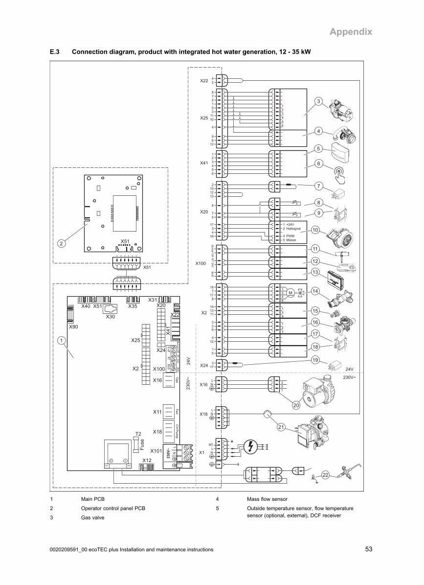
Appendix
0020209591_00 ecoTEC plus Installation and maintenance instructions 53
E.3 Connection diagram, product with integrated hot water generation, 12 - 35 kW
X18
X51
X20
X1
24V
230V~
24V
230V
~
X41
X25
654321
X22
6543
51
124
X2 1311
14
26
3
31
4
21
3
LN
X16LN
123
8177
18
6431
M
1643
17
57
8
54
21
MassePWM
Hallsignal+24V
152
1312
Burner O
ffB
US
RT
24VX100
1269
4
2
10
1
11351278
24
X24 173
X30
X40 X51 X35X31
X22
X90
2 1
T2
Fuse
X12
X25
X2
OptX16
FanX11
X18
CH Pum
p
B.offRT
BUSX100
X24
X20
X101
X41
5
X51
LRT *
N
2
1
10
21
20
3
4
18
19
14
15
16
13
12
11
8
17
6
7
9
22
1 Main PCB
2 Operator control panel PCB
3 Gas valve
4 Mass flow sensor
5 Outside temperature sensor, flow temperaturesensor (optional, external), DCF receiver

Appendix
54 Installation and maintenance instructions ecoTEC plus 0020209591_00
6 Circulation pump remote control
7 Power coding resistor
8 Return temperature sensor
9 Flow temperature sensor
10 Fan
11 Contact thermostat/burner off
12 24 V DC room thermostat
13 Bus connection (digital room thermostat/controller)
14 Diverter valve
15 Water pressure sensor
16 Impeller sensor
17 Warm start sensor
18 Hot water sensor
19 Gas group coding resistor
20 Auxiliary relay (select via D.026)
21 Internal pump
22 Ignition electrode
* Depending on product type

Appendix
0020209591_00 ecoTEC plus Installation and maintenance instructions 55
E.4 Connection diagram, product with integrated hot water generation, ≥ 37 kW
X18
X51
X20
X1
24V
230V~
24V
230V
~
X41
X25
654321
X22
6543
51
124
X2 1311
14
26
3
31
4
21
3
LN
X16LN
123
8177
18
6431
M
1643
17
57
8
54
21
MassePWM
Hallsignal+24V
152
1312
Burner O
ffB
US
RT
24VX100
1269
4
2
10
1
11351278
24
X24 173
X30
X40 X51 X35X31
X22
X90
2 1
T2
Fuse
X12
X25
X2
OptX16
FanX11
X18
CH Pum
p
B.offRT
BUSX100
X24
X20
X101
X41
5
X51
LRT *
N
X11LN
123
2
1
10
21
20
3
4
18
19
14
15
16
13
12
11
8
17
6
7
9
22
10
1 Main PCB
2 Operator control panel PCB
3 Gas valve
4 Mass flow sensor
5 Outside temperature sensor, flow temperaturesensor (optional, external), DCF receiver

Appendix
56 Installation and maintenance instructions ecoTEC plus 0020209591_00
6 Circulation pump remote control
7 Power coding resistor
8 Return temperature sensor
9 Flow temperature sensor
10 Fan
11 Contact thermostat/burner off
12 24 V DC room thermostat
13 Bus connection (digital room thermostat/controller)
14 Diverter valve
15 Water pressure sensor
16 Impeller sensor
17 Warm start sensor
18 Hot water sensor
19 Gas group coding resistor
20 Auxiliary relay (select via D.026)
21 Internal pump
22 Ignition electrode
* Depending on product type
F Inspection and maintenance work – Overview
The table below lists the manufacturer requirements with respect to minimum inspection and maintenance intervals. If na-tional regulations and directives require shorter inspection and maintenance intervals, you should observe these instead ofthe intervals listed in the table.
No. WorkInspection(annual)
Mainten-ance
(At leastevery five
years)
1Check the air/flue pipe for leak-tightness and to ensure that it is fastened correctly. Make surethat it is not blocked or damaged and has been installed in accordance with the relevant Installa-tion Manual.
X X
2Check the general condition of the product. Remove dirt from the product and from the vacuumchamber.
X X
3Visually inspect the general condition of the Thermoblock. In doing so, pay particular attentionto signs of corrosion, rust and other defects. If you notice any damage, carry out maintenancework.
X X
4Check the gas flow pressure at maximum heat input. If the gas flow pressure is not within thecorrect range, carry out maintenance work.
X X
5Check the CO₂ content (the air ratio) of the product and, if necessary, adjust it. Keep a record ofthis.
X X
6Disconnect the product from the power mains. Check that the electrical plug connections andother connections are seated correctly and correct these if necessary.
X X
7 Close the gas isolator cock and the service valves. X
8Drain the product on the water side (observe the pressure gauge). Check the pre-charge pres-sure of the expansion vessel, and top up the vessel if necessary (approx. 0.03 MPa/0.3 bar un-der the system filling pressure).
X
9 Remove the compact thermal module. X
10Check the insulating mats in the combustion area. If you notice any damage, replace the insu-lating mats. Replace the burner flange seal each time it is opened and accordingly each timemaintenance work is carried out.
X
11 Clean the heat exchanger. X
12 Check the burner for damage and replace it if necessary. X
13 Check the condensate trap in the product, clean and fill this, if required. X X
14 Install the compact thermal module. Caution: Replace the seals. X
15Products with integrated hot water generation only: If the volume of water is insufficient or theoutlet temperature is not reached, replace the secondary heat exchanger if necessary.
X
16
Products with integrated hot water generation only: Clean the filter in the cold water inlet. Re-place the filter if impurities can no longer be removed or if the filter is damaged. In this case, alsocheck the impeller sensor for dirt and damage, clean the sensor (do not use compressed air forthis) and replace the sensor if it is damaged.
X
17 Open the gas isolator cock, reconnect the product to the power mains and switch the product on. X X
18Open the service valves, fill up the product/heating installation to 0.1-0.2 MPa/1.0-2.0 bar (de-pending on the static height of the heating installation) and start the purging programme P.00.
X
19Perform a test operation of the product and heating installation, including hot water generation,and purge the system once more if necessary.
X X

Appendix
0020209591_00 ecoTEC plus Installation and maintenance instructions 57
No. WorkInspection(annual)
Mainten-ance
(At leastevery five
years)
20 Perform the gas family check. X
21 Visually inspect the ignition and burner behaviour. X X
22 Check the CO₂ content (the air ratio) of the product again. X
23 Check the product for gas, flue gas, hot water and condensate leaks, and repair if necessary. X X
24 Record the inspection/maintenance work carried out. X X

Appendix
58 Installation and maintenance instructions ecoTEC plus 0020209591_00
G Commissioning Checklist
© Heating and Hotwater Industry Council (HHIC)
www.centralheating.co.uk
Benchmark Commissioning and Servicing SectionIt is a requirement that the boiler is installed and commissioned to the
completed in full.
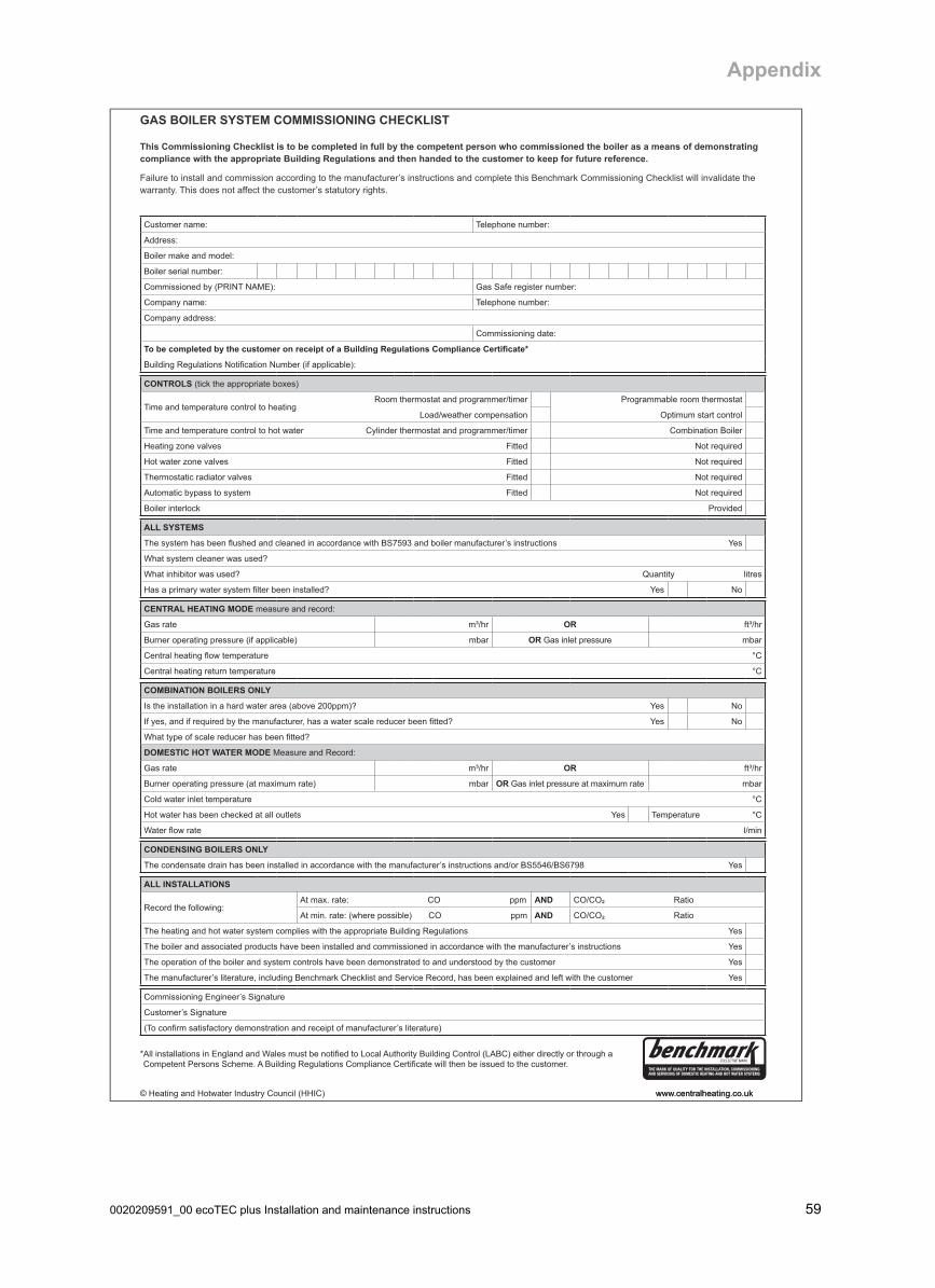
Appendix
0020209591_00 ecoTEC plus Installation and maintenance instructions 59
This Commissioning Checklist is to be completed in full by the competent person who commissioned the boiler as a means of demonstrating compliance with the appropriate Building Regulations and then handed to the customer to keep for future reference.
GAS BOILER SYSTEM COMMISSIONING CHECKLIST
CONTROLS
Optimum start control
Fitted
Fitted
Fitted
Fitted
ALL SYSTEMS
Yes
Yes
CENTRAL HEATING MODE
OR
mbar OR mbar
COMBINATION BOILERS ONLY
Yes
Yes
DOMESTIC HOT WATER MODE
OR
mbar OR mbar
Yes Temperature
CONDENSING BOILERS ONLY
Yes
ALL INSTALLATIONS
AND ² Ratio
AND ² Ratio
Yes
Yes
Yes
Yes

Appendix
60 Installation and maintenance instructions ecoTEC plus 0020209591_00
It is recommended that your heating system is serviced regularly and that the appropriate Service Interval Record is completed.
Service Provider
SERVICE RECORD
SERVICE 01
AND ² %AND ² %
SERVICE 02
AND ² %AND ² %
SERVICE 03
AND ² %AND ² %
SERVICE 04
AND ² %AND ² %
SERVICE 05
AND ² %AND ² %
SERVICE 06
AND ² %AND ² %
SERVICE 07
AND ² %AND ² %
SERVICE 08
AND ² %AND ² %
SERVICE 09
AND ² %AND ² %
SERVICE 10
AND ² %AND ² %

Appendix
0020209591_00 ecoTEC plus Installation and maintenance instructions 61
PRIOR TO CO AND COMBUSTION RATIO CHECKThe boiler manufacturer’s installation instructions should have been followed, gas type verified and gas
supply pressure/rate checked as required prior to commissioning.As part of the installation process, especially where a flue has been fitted by persons other than the boiler installer, visually check the integrity of the whole flue system to confirm that all components are correctly assembled, fixed and supported. Check that manufacturer’s max. flue lengths have not been
exceeded and all guidance has been followed (e.g. Gas Safe Technical Bulletin TB008).The flue gas analyser should be of the correct type, as specified by BS 7967
Prior to its use, the flue gas analyser should have been maintained and calibrated as specified by the manufacturer. The installer must have the relevant competence for use of the analyser.
Check and zero the analyser IN FRESH AIR as per analyser manufacturer’s instructions.
NOTETHE AIR GAS RATIO VALVE IS FACTORY
SET AND MUST NOT BE ADJUSTED DURING COMMISSIONING UNLESS THIS ACTION IS RECOMMENDED FOLLOWING CONTACT WITH THE MANUFACTURER.
If any such adjustment is recommended and further checking of the boiler is required the
installer/service engineer must be competent to carry out this work and to use the flue gas
analyser accordingly.If the boiler requires conversion to operate with
a different gas family (e.g. conversion from natural gas to LPG) separate guidance will be
provided by the boiler manufacturer
CARRY OUT FLUE INTEGRITY CHECK USING ANALYSERInsert analyser probe into air inlet test point and allow readings to stabilise.NOTE - where no air inlet test point is provided then a flue integrity check
with the analyser is not possible. The installer should verify that flue integrity has been visually checked in accordance with the “Prior to
CO and combustion ratio check” box above before proceeding to the “Check CO and combustion ratio at maximum rate” stage below.
SET BOILER TO MINIMUM RATEIn accordance with boiler instructions, set boiler to operate at minimum rate (to
minimum load condition). Allow sufficient time for combustion to stabilise.NOTE - If manufacturer’s instructions do not specify how to set boiler to minimum
rate contact Technical Helpline for advice.
CHECK CO AND COMBUSTION RATIO AT MINIMUM RATEWith boiler still set at minimum rate, insert analyser probe into flue gas sampling
point. Allow readings to stabilise before recording.NOTE - If no flue gas sampling point is present and the correct procedure is not
specified in the manual, consult boiler manufacturer for guidance.
CHECK CO AND COMBUSTION RATIO AT MAX. RATEWith boiler still set at maximum rate, insert analyser probe into flue gas
sampling point. Allow readings to stabilise before recording.NOTE - If no flue gas sampling point is present and the correct procedure is
not specified in the manual, consult boiler manufacturer for guidance.
SET BOILER TO MAXIMUM RATEIn accordance with boiler instructions, set boiler to operate at max. rate
(full load condition). Allow sufficient time for combustion to stabilise.NOTE - Do not insert analyser probe during this period to avoid
possible “flooding” of sensor.
IsCO less than 350ppm andCO/CO2 ratio
less than 0.004
IsO2 20.6%
andCO2 < 0.2%
IsCO less than 350ppm andCO/CO2 ratio
less than 0.004
BOILER IS OPERATING SATISFACTORILYno further actions required.
Ensure test points are capped, boiler case is correctly replaced and all other commissioning procedures are completed.
Complete Benchmark Checklist, recording CO and combustion ratio readings as required.
TURN OFF APPLIANCE AND CALL MANUFACTURER’S TECHNICAL HELPLINE
FOR ADVICE.THE APPLIANCE MUST NOT BE
COMMISSIONED UNTIL PROBLEMS ARE IDENTIFIED AND RESOLVED.
VERIFY FLUE INTEGRITYAnalyser readings indicate that combustion products and inlet air must be mixing. Further investigation of
the flue is therefore required.Check that flue components are assembled, fixed and supported as per boiler/flue manufacturer’s
instructions.Check that flue and flue terminal are not obstructed.
IsCO less than
335ppmand
CO/CO2 ratio less than 0.004
IsO2 20.6%
andCO2 < 0.2%
Check all seals around the appliance burner, internal flue seals, door and case seals.
Rectify where necessary.
TURN OFF APPLIANCE AND CALL MANUFACTURER’S TECHNICAL HELPLINE
FOR ADVICE.THE APPLIANCE MUST NOT BE
COMMISSIONED UNTIL PROBLEMS ARE IDENTIFIED AND RESOLVED. IF
COMMISSIONING CANNOT BE FULLY COMPLETED, THE APPLIANCE MUST BE
DISCONNECTED FROM THE GAS SUPPLY IN ACCORDANCE WITH THE GSIUR.
NOTE: Check and record CO and combustion ratio at both max. and min. rate before contacting the
manufacturer.
NO
NO
NO
NO
NO
YES
YES
YESYES
YES
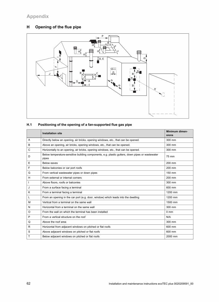
Appendix
62 Installation and maintenance instructions ecoTEC plus 0020209591_00
H Opening of the flue pipe
GN
N
MM
A
II
O
H
H
CBLJ
Q Q
Q
Q
Q
K
P
D, EF
I
S
R
T
H.1 Positioning of the opening of a fan-supported flue gas pipe
Installation siteMinimum dimen-sions
A Directly below an opening, air bricks, opening windows, etc., that can be opened. 300 mm
B Above an opening, air bricks, opening windows, etc., that can be opened. 300 mm
C Horizontally to an opening, air bricks, opening windows, etc., that can be opened. 300 mm
DBelow temperature-sensitive building components, e.g. plastic gutters, down pipes or wastewaterpipes
75 mm
E Below eaves 200 mm
F Below balconies or car port roofs 200 mm
G From vertical wastewater pipes or down pipes 150 mm
H From external or internal corners 200 mm
I Above floors, roofs or balconies 300 mm
J From a surface facing a terminal 600 mm
K From a terminal facing a terminal 1200 mm
L From an opening in the car port (e.g. door, window) which leads into the dwelling 1200 mm
M Vertical from a terminal on the same wall 1500 mm
N Horizontal from a terminal on the same wall 300 mm
O From the wall on which the terminal has been installed 0 mm
P From a vertical structure on the roof N/A
Q Above the roof area 300 mm
R Horizontal from adjacent windows on pitched or flat roofs 600 mm
S Above adjacent windows on pitched or flat roofs 600 mm
T Below adjacent windows on pitched or flat roofs 2000 mm

Appendix
0020209591_00 ecoTEC plus Installation and maintenance instructions 63
I Text from BS 5440-1 on fan-supported flue gas pipes
BS 5440–1: It is recommended that the fanned flue gas system terminal is positioned as follows:
– At least 2 m from an opening in the building directly opposite, and
– So that the combustion products are not discharged directly across a property boundary.
– Dimensions D, E, F and G: These clearances may be reduced to 25 mm without affecting the performance of the boiler.In order to ensure that the condensate vapour plume does not damage adjacent surfaces, the terminal should be exten-ded as shown.
– Dimension H: This clearance may be reduced to 25 mm without adversely affecting the performance of the boiler. How-ever, in order to ensure that the condensate vapour plume does not damage adjacent surfaces, a clearance of 300 mm ispreferred. For IE, recommendations are given in the current issue of the IS 813.
J Opening of the flue pipe below eaves and balconies
Balcony/eaves
Gutter
Adequately secured air/flue gas pipe
The flue pipe mustprotrude beyond any overhang
K Technical data
Technical data – General
612 (VU GB126/5‑5 A)ecoTEC plus
615 (VU GB156/5‑5 A)ecoTEC plus
618 (VU GB186/5‑5 A)ecoTEC plus
624 (VU GB246/5‑5 A)ecoTEC plus
630 (VU GB306/5‑5 A)ecoTEC plus
637 (VU GB376/5‑5 A)ecoTEC plus
Designated country (des-ignation in accordancewith ISO 3166)
GB (GreatBritain), IE(Ireland)
GB (GreatBritain), IE(Ireland)
GB (GreatBritain), IE(Ireland)
GB (GreatBritain), IE(Ireland)
GB (GreatBritain), IE(Ireland)
GB (GreatBritain), IE(Ireland)
Approved unit categories I2H I2H II2H3P II2H3P II2H3P II2H3P
Gas connection, boilerside
15 mm 15 mm 15 mm 15 mm 15 mm 15 mm
Flow/return heating con-nections, boiler side
22 mm 22 mm 22 mm 22 mm 22 mm 22 mm
Hot and cold water con-nection, boiler side
Expansion relief valveconnector (min.)
15 mm 15 mm 15 mm 15 mm 15 mm 15 mm
Air/flue gas connection 60/100 mm 60/100 mm 60/100 mm 60/100 mm 60/100 mm 60/100 mm
Condensate drain pipe-work (min.)
19 mm 19 mm 19 mm 19 mm 19 mm 19 mm
G20 natural gas flowpressure
2.0 kPa
(20.0 mbar)
2.0 kPa
(20.0 mbar)
2.0 kPa
(20.0 mbar)
2.0 kPa
(20.0 mbar)
2.0 kPa
(20.0 mbar)
2.0 kPa
(20.0 mbar)
G31 propane gas flowpressure
3.7 kPa
(37.0 mbar)
3.7 kPa
(37.0 mbar)
3.7 kPa
(37.0 mbar)
3.7 kPa
(37.0 mbar)
Gas flow rate at 15 °Cand 1013 mbar (based onhot water generation, ifapplicable), G20
1.3 m³/h 1.7 m³/h 2.0 m³/h 2.6 m³/h 3.7 m³/h 4.1 m³/h

Appendix
64 Installation and maintenance instructions ecoTEC plus 0020209591_00
612 (VU GB126/5‑5 A)ecoTEC plus
615 (VU GB156/5‑5 A)ecoTEC plus
618 (VU GB186/5‑5 A)ecoTEC plus
624 (VU GB246/5‑5 A)ecoTEC plus
630 (VU GB306/5‑5 A)ecoTEC plus
637 (VU GB376/5‑5 A)ecoTEC plus
Gas flow rate at 15 °Cand 1013 mbar (based onhot water generation, ifapplicable), G31
1.5 kg/h 1.9 kg/h 2.4 kg/h 3.0 kg/h
Min. flue gas mass rate(G20)
1.44 g/s 1.44 g/s 1.80 g/s 2.47 g/s 2.78 g/s 3.05 g/s
Min. flue gas mass rate(G31)
2.40 g/s 2.90 g/s 4.08 g/s 4.08 g/s
Max. flue gas mass rate 5.6 g/s 7.0 g/s 8.4 g/s 11.1 g/s 13.9 g/s 17.4 g/s
Min. flue gas temperature 40 ℃ 40 ℃ 40 ℃ 40 ℃ 40 ℃ 40 ℃
Max. flue gas temperat-ure
70 ℃ 70 ℃ 70 ℃ 70 ℃ 70 ℃ 70 ℃
Approved gas-fired units C13, C33,C43, C53
C13, C33,C43, C53
C13, C33,C43, C53
C13, C33,C43, C53
C13, C33,C43, C53
C13, C33,C43, C53
30% efficiency 108 % 108 % 108.5 % 109 % 109 % 108.5 %
NOx class 5 5 5 5 5 5
SEDBUK (2005) A A A A A A
SEDBUK (2009)(G20/G31)
89.3 % 89.3 % 89.3 % 89.3 % 89.3 % 89.3 %
Boiler dimension, width 440 mm 440 mm 440 mm 440 mm 440 mm 440 mm
Boiler dimension, height 720 mm 720 mm 720 mm 720 mm 720 mm 720 mm
Boiler dimension, depth 338 mm 338 mm 338 mm 338 mm 372 mm 406 mm
Mounting weight 36 kg 36 kg 36 kg 37 kg 38 kg 43 kg
825 (VUWGB 256/5‑5)ecoTEC plus
832 (VUWGB 326/5‑5)ecoTEC plus
835 (VUWGB 356/5‑5)ecoTEC plus
838 (VUWGB 386/5‑5)ecoTEC plus
Designated country (des-ignation in accordancewith ISO 3166)
GB (GreatBritain), IE(Ireland)
GB (GreatBritain), IE(Ireland)
GB (GreatBritain), IE(Ireland)
GB (GreatBritain), IE(Ireland)
Approved unit categories II2H3P II2H3P II2H3P II2H3P
Gas connection, boilerside
15 mm 15 mm 15 mm 15 mm
Flow/return heating con-nections, boiler side
22 mm 22 mm 22 mm 22 mm
Hot and cold water con-nection, boiler side
G 3/4″ G 3/4″ G 3/4″ G 3/4″
Expansion relief valveconnector (min.)
15 mm 15 mm 15 mm 15 mm
Air/flue gas connection 60/100 mm 60/100 mm 60/100 mm 60/100 mm
Condensate drain pipe-work (min.)
19 mm 19 mm 19 mm 19 mm
G20 natural gas flowpressure
2.0 kPa
(20.0 mbar)
2.0 kPa
(20.0 mbar)
2.0 kPa
(20.0 mbar)
2.0 kPa
(20.0 mbar)
G31 propane gas flowpressure
3.7 kPa
(37.0 mbar)
3.7 kPa
(37.0 mbar)
3.7 kPa
(37.0 mbar)
3.7 kPa
(37.0 mbar)
Gas flow rate at 15 °Cand 1013 mbar (based onhot water generation, ifapplicable), G20
2.7 m³/h 3.4 m³/h 3.8 m³/h 4.2 m³/h
Gas flow rate at 15 °Cand 1013 mbar (based onhot water generation, ifapplicable), G31
2.0 kg/h 2.5 kg/h 2.8 kg/h 3.1 kg/h
Min. flue gas mass rate(G20)
1.80 g/s 2.47 g/s 2.78 g/s 3.05 g/s

Appendix
0020209591_00 ecoTEC plus Installation and maintenance instructions 65
825 (VUWGB 256/5‑5)ecoTEC plus
832 (VUWGB 326/5‑5)ecoTEC plus
835 (VUWGB 356/5‑5)ecoTEC plus
838 (VUWGB 386/5‑5)ecoTEC plus
Min. flue gas mass rate(G31)
2.40 g/s 2.90 g/s 4.08 g/s 4.08 g/s
Max. flue gas mass rate 8.4 g/s 11.1 g/s 16.2 g/s 17.9 g/s
Min. flue gas temperature 40 ℃ 40 ℃ 40 ℃ 40 ℃
Max. flue gas temperat-ure
70 ℃ 70 ℃ 70 ℃ 70 ℃
Approved gas-fired units C13, C33,C43, C53
C13, C33,C43, C53
C13, C33,C43, C53
C13, C33,C43, C53
30% efficiency 108.5 % 109 % 109 % 109 %
NOx class 5 5 5 5
SEDBUK (2005) A A A A
SEDBUK (2009)(G20/G31)
89.3 % 89.3 % 89.3 % 89.3 %
Boiler dimension, width 440 mm 440 mm 440 mm 440 mm
Boiler dimension, height 720 mm 720 mm 720 mm 720 mm
Boiler dimension, depth 338 mm 338 mm 372 mm 406 mm
Mounting weight 36 kg 37 kg 38 kg 43 kg
Technical data – G20 power/loading G20
612 (VU GB126/5‑5 A)ecoTEC plus
615 (VU GB156/5‑5 A)ecoTEC plus
618 (VU GB186/5‑5 A)ecoTEC plus
624 (VU GB246/5‑5 A)ecoTEC plus
630 (VU GB306/5‑5 A)ecoTEC plus
637 (VU GB376/5‑5 A)ecoTEC plus
Nominal heat outputrange P at 50/30 °C
3.3… 12.9 kW
3.3… 16.1 kW
4.2… 19.3 kW
5.7… 25.7 kW
6.4… 32.2 kW
7.1… 39.6 kW
Nominal heat outputrange P at 80/60 °C
3.0… 12.2 kW
3.0… 15.4 kW
3.8… 18.5 kW
5.2… 24.4 kW
5.8… 30.4 kW
6.4… 37.6 kW
Maximum heat output forhot water generation
12.2 kW 15.4 kW 18.5 kW 24.4 kW 30.4 kW 37.6 kW
Maximum heat input forhot water generation
12.4 kW 15.7 kW 18.9 kW 24.9 kW 31.0 kW 38.4 kW
Maximum heat input,heating side
12.4 kW 15.5 kW 18.6 kW 24.7 kW 30.9 kW 38.1 kW
Minimum heat input 3.2 kW 3.2 kW 4.0 kW 5.5 kW 6.2 kW 6.8 kW
Heating adjustment range 3 … 12 kW 3 … 15 kW 4 … 19 kW 5 … 24 kW 6 … 30 kW 6 … 38 kW
825 (VUWGB 256/5‑5)ecoTEC plus
832 (VUWGB 326/5‑5)ecoTEC plus
835 (VUWGB 356/5‑5)ecoTEC plus
838 (VUWGB 386/5‑5)ecoTEC plus
Nominal heat outputrange P at 50/30 °C
4.2… 20.4 kW
5.7… 25.7 kW
6.4… 32.2 kW
7.1… 30.1 kW
Nominal heat outputrange P at 80/60 °C
3.8… 19.3 kW
5.2… 24.4 kW
5.8… 30.4 kW
6.4… 28.6 kW
Maximum heat output forhot water generation
25.4 kW 31.8 kW 35.0 kW 38.7 kW
Maximum heat input forhot water generation
25.9 kW 32.4 kW 35.7 kW 39.5 kW
Maximum heat input,heating side
19.6 kW 24.7 kW 31.0 kW 28.9 kW
Minimum heat input 4.0 kW 5.5 kW 6.2 kW 6.8 kW
Heating adjustment range 4 … 19 kW 5 … 24 kW 6 … 30 kW 6 … 29 kW

Appendix
66 Installation and maintenance instructions ecoTEC plus 0020209591_00
Technical data – Power/loading G31
618 (VU GB186/5‑5 A)ecoTEC plus
624 (VU GB246/5‑5 A)ecoTEC plus
630 (VU GB306/5‑5 A)ecoTEC plus
637 (VU GB376/5‑5 A)ecoTEC plus
825 (VUWGB 256/5‑5)ecoTEC plus
832 (VUWGB 326/5‑5)ecoTEC plus
Nominal heat outputrange P at 50/30 °C
5.5… 19.3 kW
6.7… 25.7 kW
9.4… 32.1 kW
9.4… 39.6 kW
5.5… 19.3 kW
6.7… 25.7 kW
Nominal heat outputrange P at 80/60 °C
5.0… 18.5 kW
6.0… 24.4 kW
8.5… 30.4 kW
8.5… 37.6 kW
5.0… 19.3 kW
6.0… 24.4 kW
Maximum heat output forhot water generation
18.5 kW 24.4 kW 30.4 kW 37.6 kW 25.4 kW 31.8 kW
Maximum heat input forhot water generation
18.9 kW 24.9 kW 31.0 kW 38.4 kW 25.9 kW 32.4 kW
Maximum heat input,heating side
18.6 kW 24.7 kW 30.9 kW 38.1 kW 19.6 kW 24.7 kW
Minimum heat input 5.3 kW 6.4 kW 9.0 kW 9.0 kW 5.3 kW 6.4 kW
835 (VUWGB 356/5‑5)ecoTEC plus
838 (VUWGB 386/5‑5)ecoTEC plus
Nominal heat outputrange P at 50/30 °C
9.4… 32.1 kW
9.4… 30.1 kW
Nominal heat outputrange P at 80/60 °C
8.5… 30.4 kW
8.5… 28.6 kW
Maximum heat output forhot water generation
35.0 kW 38.7 kW
Maximum heat input forhot water generation
35.7 kW 39.5 kW
Maximum heat input,heating side
30.9 kW 28.9 kW
Minimum heat input 9.0 kW 9.0 kW
Technical data – Heating
612 (VU GB126/5‑5 A)ecoTEC plus
615 (VU GB156/5‑5 A)ecoTEC plus
618 (VU GB186/5‑5 A)ecoTEC plus
624 (VU GB246/5‑5 A)ecoTEC plus
630 (VU GB306/5‑5 A)ecoTEC plus
637 (VU GB376/5‑5 A)ecoTEC plus
Maximum flow temperat-ure
85 ℃ 85 ℃ 85 ℃ 85 ℃ 85 ℃ 85 ℃
Max. flow temperatureadjustment range (defaultsetting: 75 °C)
30 … 80 ℃ 30 … 80 ℃ 30 … 80 ℃ 30 … 80 ℃ 30 … 80 ℃ 30 … 80 ℃
Permissible total over-pressure
0.3 MPa
(3.0 bar)
0.3 MPa
(3.0 bar)
0.3 MPa
(3.0 bar)
0.3 MPa
(3.0 bar)
0.3 MPa
(3.0 bar)
0.3 MPa
(3.0 bar)
Minimum pressure forfull operation
0.08 MPa
(0.80 bar)
0.08 MPa
(0.80 bar)
0.08 MPa
(0.80 bar)
0.08 MPa
(0.80 bar)
0.08 MPa
(0.80 bar)
0.08 MPa
(0.80 bar)
Expansion vessel capa-city
10 l 10 l 10 l 10 l 10 l 10 l
Circulation water volume(with reference toΔT= 20 K)
525 l/h 662 l/h 796 l/h 1,049 l/h 1,307 l/h 1,617 l/h
Approx. condensate rate(pH value 3.5 to 4.0) in50/30 °C heating mode
1.2 l/h 1.6 l/h 1.9 l/h 2.5 l/h 3.1 l/h 3.8 l/h
Remaining feed head ofpump (at nominal circula-tion water volume)
0.025 MPa
(0.250 bar)
0.025 MPa
(0.250 bar)
0.025 MPa
(0.250 bar)
0.025 MPa
(0.250 bar)
0.025 MPa
(0.250 bar)
0.025 MPa
(0.250 bar)

Appendix
0020209591_00 ecoTEC plus Installation and maintenance instructions 67
825 (VUWGB 256/5‑5)ecoTEC plus
832 (VUWGB 326/5‑5)ecoTEC plus
835 (VUWGB 356/5‑5)ecoTEC plus
838 (VUWGB 386/5‑5)ecoTEC plus
Maximum flow temperat-ure
85 ℃ 85 ℃ 85 ℃ 85 ℃
Max. flow temperatureadjustment range (defaultsetting: 75 °C)
30 … 80 ℃ 30 … 80 ℃ 30 … 80 ℃ 30 … 80 ℃
Permissible total over-pressure
0.3 MPa
(3.0 bar)
0.3 MPa
(3.0 bar)
0.3 MPa
(3.0 bar)
0.3 MPa
(3.0 bar)
Minimum pressure forfull operation
0.08 MPa
(0.80 bar)
0.08 MPa
(0.80 bar)
0.08 MPa
(0.80 bar)
0.08 MPa
(0.80 bar)
Expansion vessel capa-city
10 l 10 l 10 l 10 l
Circulation water volume(with reference toΔT= 20 K)
830 l/h 1,049 l/h 1,307 l/h 1,230 l/h
Approx. condensate rate(pH value 3.5 to 4.0) in50/30 °C heating mode
2.0 l/h 2.5 l/h 3.1 l/h 2.9 l/h
Remaining feed head ofpump (at nominal circula-tion water volume)
0.025 MPa
(0.250 bar)
0.025 MPa
(0.250 bar)
0.025 MPa
(0.250 bar)
0.025 MPa
(0.250 bar)
Technical data – Hot water handling
825 (VUWGB 256/5‑5)ecoTEC plus
832 (VUWGB 326/5‑5)ecoTEC plus
835 (VUWGB 356/5‑5)ecoTEC plus
838 (VUWGB 386/5‑5)ecoTEC plus
Lowest water volume 2.0 l/min 2.0 l/min 2.0 l/min 2.0 l/min
Water volume (atΔT = 30 K)
12.3 l/min 15.2 l/min 16.7 l/min 18.5 l/min
Water volume (atΔT = 35 K)
10.5 l/min 13.0 l/min 14.3 l/min 15.9 l/min
Water volume (atΔT = 42 K)
8.8 l/min 10.9 l/min 11.9 l/min 13.2 l/min
Permitted overpressure 1.0 MPa
(10.0 bar)
1.0 MPa
(10.0 bar)
1.0 MPa
(10.0 bar)
1.0 MPa
(10.0 bar)
Required connectionpressure
0.035 MPa
(0.350 bar)
0.035 MPa
(0.350 bar)
0.035 MPa
(0.350 bar)
0.035 MPa
(0.350 bar)
Hot water output temper-ature range
35 … 65 ℃ 35 … 65 ℃ 35 … 65 ℃ 35 … 65 ℃
Technical data – Electrics
612 (VU GB126/5‑5 A)ecoTEC plus
615 (VU GB156/5‑5 A)ecoTEC plus
618 (VU GB186/5‑5 A)ecoTEC plus
624 (VU GB246/5‑5 A)ecoTEC plus
630 (VU GB306/5‑5 A)ecoTEC plus
637 (VU GB376/5‑5 A)ecoTEC plus
Electric connection 230 V/50 Hz 230 V/50 Hz 230 V/50 Hz 230 V/50 Hz 230 V/50 Hz 230 V/50 Hz
Permissible connectedvoltage
190 … 253 V 190 … 253 V 190 … 253 V 190 … 253 V 190 … 253 V 190 … 253 V
Built-in fuse (slow-blow) 2 A 2 A 2 A 2 A 2 A 2 A
Min. electrical power con-sumption
35 W 35 W 35 W 35 W 45 W 55 W
Max. electrical powerconsumption
50 W 55 W 65 W 70 W 80 W 115 W
Standby electrical powerconsumption
< 2 W < 2 W < 2 W < 2 W < 2 W < 3 W
Level of protection IP X4 D IP X4 D IP X4 D IP X4 D IP X4 D IP X4 D
Test symbol/registrationno.
CE‑0085CM0320
CE‑0085CM0320
CE‑0085CM0320
CE‑0085CM0320
CE‑0085CM0320
CE‑0085CM0320

Appendix
68 Installation and maintenance instructions ecoTEC plus 0020209591_00
825 (VUWGB 256/5‑5)ecoTEC plus
832 (VUWGB 326/5‑5)ecoTEC plus
835 (VUWGB 356/5‑5)ecoTEC plus
838 (VUWGB 386/5‑5)ecoTEC plus
Electric connection 230 V/50 Hz 230 V/50 Hz 230 V/50 Hz 230 V/50 Hz
Permissible connectedvoltage
190 … 253 V 190 … 253 V 190 … 253 V 190 … 253 V
Built-in fuse (slow-blow) 2 A 2 A 2 A 2 A
Min. electrical power con-sumption
35 W 35 W 45 W 55 W
Max. electrical powerconsumption
65 W 85 W 90 W 120 W
Standby electrical powerconsumption
< 2 W < 2 W < 2 W < 3 W
Level of protection IP X4 D IP X4 D IP X4 D IP X4 D
Test symbol/registrationno.
CE‑0085CM0320
CE‑0085CM0320
CE‑0085CM0320
CE‑0085CM0320

Index
0020209591_00 ecoTEC plus Installation and maintenance instructions 69
Index
AAir index setting................................................................... 25Air/flue pipe ......................................................................... 16Air/flue pipe, installed ............................................................ 5Appliance config. ................................................................. 26Article number ..................................................................... 10Automatic air vent................................................................ 22Auxiliary relay ...................................................................... 19BBurner anti-cycling time....................................................... 26Burner anti-cycling time, resetting ....................................... 27Burner anti-cycling time, setting .......................................... 26Burner, replacing ................................................................. 29Bypass valve, setting........................................................... 28CCalling up, diagnostics codes ............................................. 26Calling up, fault memory...................................................... 29Calling up, installer level...................................................... 18Carrying out, inspection work .............................................. 33Carrying out, maintenance work.......................................... 33CE label ............................................................................... 10Check programmes ............................................................. 20Checking the burner ............................................................ 35Checking, burner ................................................................. 35Checking, CO₂ content ........................................................ 25Checking, pre-charge pressure for the internal expansionvessel .................................................................................. 36Circulation pump ................................................................. 18Cleaning, cold water inlet filter ............................................ 35Cleaning, heat exchanger .................................................. 35Clearing, fault memory ........................................................ 29CO₂ content, checking......................................................... 25CO₂ content, setting ............................................................ 25Cold water connection......................................................... 14Cold water inlet filter, cleaning ............................................ 35Combustion air ...................................................................... 6Comfort mode...................................................................... 19Comfort protection mode..................................................... 29Compact thermal module ...................................................... 6Compact thermal module, installing .................................... 36Compact thermal module, removing ................................... 34Completing, inspection work ............................................... 36Completing, maintenance work ........................................... 36Completing, repair work ...................................................... 33Component test ................................................................... 34Condensate drain pipework................................................. 15Condensate siphon ....................................................... 23, 35Condensate trap............................................................ 23, 35Connecting, controller ......................................................... 18Connection dimensions ....................................................... 11Contact details..................................................................... 20Controller, connecting ......................................................... 18Corrosion............................................................................... 6Corrugated gas pipe.............................................................. 6DDecommissioning ................................................................ 37Decommissioning, temporarily ............................................ 36Diagnostics codes, calling up .............................................. 26Discharge pipe, expansion relief valve................................ 16Disposal, packaging ............................................................ 37
Disposing of the packaging ................................................. 37Documents ............................................................................ 8Draining, product ................................................................. 36EElectricity ............................................................................... 5Electronics box, closing....................................................... 17Electronics box, opening ..................................................... 17Electronics self-test ............................................................. 34Ending, installation assistant ............................................... 20FFan, replacing...................................................................... 30Fault codes.................................................................... 29, 46Fault memory, calling up ..................................................... 29Fault memory, deleting........................................................ 29Fault messages ................................................................... 29Filling ................................................................................... 22Filling mode ......................................................................... 19Flue gas route ....................................................................... 5From the delivery point to the installation site ..................... 11Front casing, closed .............................................................. 5Frost ...................................................................................... 6Function menu..................................................................... 34GGas conversion ................................................................... 23Gas family check, performing.............................................. 20Gas ratio setting .................................................................. 23Gas restrictor....................................................................... 31Gas valve ............................................................................ 30Gas valve, replacing............................................................ 30HHanding over to the operator............................................... 28Handling .............................................................................. 11Heat exchanger, cleaning.................................................... 35Heat exchanger, replacing .................................................. 32Heating flow......................................................................... 15Heating partial load ............................................................. 19Heating return...................................................................... 15Hot water connection........................................................... 14Hot water temperature......................................................... 19IIdentification plate ................................................................. 9If you smell gas ..................................................................... 4Inspection work, carrying out............................................... 33Inspection work, completing ................................................ 36Installation assistant, ending ............................................... 20Installation assistants, restarting ......................................... 20Installation site................................................................... 5–6Installer level, calling up ...................................................... 18Installing, compact thermal module..................................... 36Installing, unit connection piece with offset ......................... 16Installing, unit connection piece, 80/125 mm diameter ....... 16Intended use.......................................................................... 4Internal expansion vessel, replacing ................................... 32Isolator devices ................................................................... 36LLanguage ............................................................................ 19Leak detection spray ............................................................. 6Liquid gas ........................................................................ 4, 14MMains connection ................................................................ 17Maintenance interval, setting............................................... 27Maintenance work, carrying out .......................................... 33

Index
70 Installation and maintenance instructions ecoTEC plus 0020209591_00
Maintenance work, completing............................................ 36Mass flow sensor, replacing ................................................ 31Minimum clearance ............................................................. 12Multi-functional module ....................................................... 19OOperating concept ............................................................... 18PPCB and display, replacing ................................................. 33PCB or display, replacing .................................................... 33Performing, gas family check .............................................. 20Power supply....................................................................... 17Pre-charge pressure for the internal expansion vessel,checking .............................................................................. 36Preparing, repair work ......................................................... 29Pressure gauge ..................................................................... 9Product dimensions............................................................. 11Product, draining ................................................................. 36Product, switching off .......................................................... 36Pump output, setting ........................................................... 27Pump, remaining feed head ................................................ 27Purging ................................................................................ 23RRegulations ........................................................................... 6Remaining feed head, pump ............................................... 27Removing, compact thermal module................................... 34Removing, unit connection piece for the air/flue pipe ......... 16Repair work, completing...................................................... 33Repair work, preparing ........................................................ 29Replacing the burner ........................................................... 29Replacing, fan ..................................................................... 30Replacing, gas valve ........................................................... 30Replacing, heat exchanger.................................................. 32Replacing, internal expansion vessel .................................. 32Replacing, mass flow sensor............................................... 31Replacing, PCB and display................................................ 33Replacing, PCB or display................................................... 33Replacing, unit connection piece for the air/flue pipe.......... 16Replacing, Venturi ............................................................... 31Resetting, burner anti-cycling time...................................... 27SSafety device......................................................................... 5Schematic drawing ................................................................ 5Scope of delivery................................................................. 10Self-test ............................................................................... 34Serial number ...................................................................... 10Service message................................................................. 29Setting, burner anti-cycling time .......................................... 26Setting, bypass valve .......................................................... 28Setting, CO₂ content............................................................ 25Setting, maintenance interval .............................................. 27Setting, pump output ........................................................... 27Side section, installing......................................................... 13Side section, removing ........................................................ 13Spare parts.......................................................................... 29Starting, installation assistants ............................................ 20Status codes.................................................................. 19, 44Supply of combustion air ....................................................... 5Switching off ........................................................................ 19Switching off, product .......................................................... 36Switching on ........................................................................ 19TTarget feed temperature...................................................... 19
Telephone number, competent person ............................... 20Test programmes ................................................................ 20Tool ....................................................................................... 6Treating the heating water .................................................. 21UUnit connection piece for the air/flue pipe, removing .......... 16Unit connection piece for the air/flue pipe, replacing .......... 16Unit connection piece with offset, installing......................... 16Unit connection piece, 80/125 mm diameter, installing....... 16Unloading the box ............................................................... 11VVenturi ................................................................................. 30Venturi, replacing ................................................................ 31Voltage .................................................................................. 5WWeight ................................................................................. 12


0020209591_00 21.05.2015
Vaillant Ltd.
Nottingham Road Belper Derbyshire DE56 1JT
Telephone 03 30 100‑34 61 Telephone (renewables) 02 07 022‑09 28
Vaillant Service Solutions 03 30 100‑31 43 Spares Technical Enquiries 177 359 66 15
[email protected] [email protected]
www.vaillant.co.uk
© These instructions, or parts thereof, are protected by copyright and may be reproduced or distributed only withthe manufacturer's written consent.