Embed Size (px)
Citation preview

JKAU: Eng. Sci., vol. 16 no. 2, pp: 55-82 (2006 A.D./1427 A.H.)
55
Economic feasibility of thermal energy storage systems:
Application to Al-Haram Grand Holy Mosque
air conditioning plant
B. A. HABEEBULLAH
Faculty of Engineering, King Abdulaziz University, P. O. Box 80204,
Jeddah 21589, Saudi Arabia
ABSTRACT. In hot aired countries with sever weather, cooling and air conditioning of buildings contributes significantly to the electricity peak demand, which normally occurs during noontime period. Shifting the electrical loads to off-peak periods is achieved by introducing time of rate tariff as incentive control on the demand-side and/or using active thermal energy storage technology. This paper investigates the economic feasibility of both building an ice thermal energy storage and a timely based tariff structure for the unique air conditioning plant of the Grand Holy Mosque of Makkah, Saudi Arabia (the largest religious building on earth). The features of the building are unique where the air-conditioned 39300 m2 zone is open to the atmosphere and the worshippers fully occupy the building 5 times a day. Hundreds of thousands of worshippers attend the blessed Friday prayer at noontime, which escalates the peak electricity load. For economic analysis, the objective function is the daily electricity bill that includes the operation cost and the capital investment of the ice storage system. The operation cost is a function of the energy imported for operating the plant in which the tariff structure, number of operating hours and the ambient temperature are parameters. The capital recovery factor is calculated for 10% interest rate and payback period of 10 years. Full and partial load storage scenarios are considered.
The results showed that with the current fixed electricity rate (0.07 $/kWh), there is no gain in introducing ice storage systems neither for full nor for partial storage schemes. Combining energy storage and an incentive time structured rate showed reasonable daily bill savings. For base tariff of 0.07 $/kWh during daytime operation and 0.016 $/kWh for off-peak period, savings of 549.4 $/d was achieved for full load storage scenario. the storage capital cost will be paid in 10 years and afterwards the daily saving in operational cost will be 4011.76 $/d.
B. A. Habeebullah
56
Different tariff structure is discussed and the break-even nighttime rate was determined (varies between 0.008 and 0.03 $/kWh). Partial load storage scenario showed to be unattractive where the savings for the base structured tariff was insignificant.
KEY WORDS: ice storage; religious building; cooling load; economic analysis.
.
1. Introduction
In today's fast-paced economy and unstable fuel market, energy conservation is becoming an important issue. Electricity generation authorities focus attention on programs to reduce the demand and/or achieve optimum generation cost. The energy economy can be sufficiently improved by employing techniques to either tame the energy demand and/or effectively utilize the available resources. Air conditioning (A/C) systems are major contributors to buildings' energy consumption, in hot climate locations 60% of the energy is consumed for A/C. Therefore, improving A/C systems performance will not only reduce the demand but also can significantly reduce the future capital investment in building new power plants.
Several methods are currently in use to save energy in buildings, they can be classified into passive and active methods. For the passive techniques heat loads of buildings are reduced by using any of the thermal energy reduction methods, this include shading of facades and fenestrations, use of thermal insulation material, proper orientation of buildings' envelop. Management of the heat loads thorough dynamic tariff strategy, optimum operation scheme and energy storage policy are examples of the active methods. The principal idea in using thermal energy storage (TES) is shifting the electricity peak load associated with buildings' cooling from peak time to off-peak periods. In general, TES is considered by utilities as demand management strategy, which is suitable for specific applications. The concept of thermal energy storage has been employed long ago for solar energy applications; recently with the vast

Economic feasibility of thermal energy storage systems
57
increase of A/C energy demand, cold TES technology appeared to provide a feasible solution for solving peak load problems [1-3]. In hot climate areas where reliance on air conditioning increases, the maximum cooling loads of buildings occur during midday period. At the same time the performance of generating units, specially gas turbine plants, drops because of the high inlet air temperature to the compressor [4]. Though use of cold storage seems to be a promising technology, its implementation depends on the variation of the daily cooling load. The latter depends on the features of the building and occupants activities. Cold storage systems have been practically used for buildings of different features. Hasnain et al [5 and 6] investigated the prospects of using cold thermal storage for office buildings in the hot weather of Saudi Arabia. Successful application to buildings of high cooling loads (above 100000 TR-h capacity) is reported, Baltimore [7]. The TES is quite adequate simple technology for buildings with only daytime working hours and closed during nighttime and weekends. Applications cover a wide range of facility types, but most commonly are offices, schools [8], court-hall [9], campus buildings [10], retail stores [7], subway station [11], hospitals and places of worship [12 -14]. The load profile for religious buildings has been investigated in many countries for churches, synagogues and mosques [14]. In general, religious buildings heat loads whether it is heating or cooling are not very high because of the limited activities of the worshippers and the short occupation periods. Exceptions are the two grand mosques; Al-Haram Grand Holy Mosque in Makkah and the Profits' Mosque at Madina, Saudi Arabia, where the cooling capacities are 13440 TR and 24000 TR, respectively. The air conditioning plant of the Grand Holy Mosque is the subject of the present study where introducing ice storage system is investigated.
There are many studies related to the theoretical modeling, experimental simulation and cost analysis of TES. Most of the studies are based on sole thermo-fluid analysis of TES [15-18] or searching for optimal control strategy to maximize a kind of an objective function. The objective function can be net energy saving, cost, comfort condition or any combination of these. Chen et al [15] presented a simulation model based on detailed heat transfer analysis of ice storage for air conditioning systems. In their model, a direct heat transfer evaporator with (R-22)

B. A. Habeebullah
58
primary refrigerant was considered for ice formation. They calculated the rate of ice formation on finned tubes and showed that heat transfer efficiency on the flat plates is higher than that on the curved tube sections. Silver, et al [16] modeled a refrigeration unit coupled to an ice storage tank for load shaving. The model was based on spatial thermo-fluids analysis of the evaporator coil. Other systems [17-19] use brine or Glycol as the cooling medium for ice formation, for this case an intermediate closed loop is integrated between the refrigeration machine and the ice storage tank. Therefore, the analysis is based on single-phase flow inside pipes with ice formation on the outer surface.
Kawada et al [20] conducted an experimental study on large capacity ice storage tanks investigated both static and dynamic modes of energy storage. The objective of that work was mainly devoted to explore different freezing methods, capsulated flakes ice for static testing and super-cooling brine for dynamic experiments. West and Braun [21] presented two models to predict the performance of ice storage tanks with partial charging and discharging scenarios. Saito [22] reviewed advances in the field of energy storage where he compared the different types of energy storage systems.
Successful operation of ice storage systems is not limited to only thermo-fluid analysis (which is important to size out the equipment) but extends to include cost analysis, which is a deterministic factor. Sizing out of ice storage tanks depends technically on the energy to be stored and the operation period. Manufacturers' guidelines and even ASHRAE procedure [23] focus on simplified schemes for shifting the electrical energy from peak to off peak periods. These methods do not provide conclusive information as to the work scheme for maximum possible savings.
Because of the growing concern on energy conservation, many utilities have adopted time of use (TOU) tariff, which opened a wide door for the use of energy storage systems. Therefore, recent studies are direct to search for storage systems suitable for specific type of buildings that maximize the net annual savings [24 - 26]. Installing or retrofitting an energy storage system is becoming an economic problem related to the cooling load and the features of the buildings. Henze and Krarti [27]
Economic feasibility of thermal energy storage systems
59
defined the cost function as the summation of demand charge, which consists of the electrical energy (kWh) cost and the total peak power consumption cost. A simplified plant model was implemented taking into account the components of a cooling system [28]. This model includes the environment parameters (i.e. load capacity and electrical rate structure). Ihm et al [29] extended the previous studies and integrated a TES simulation model within the EnergyPlus buildings analysis package [30] to determine potential cost savings under different control strategies. Henz et al [31] carried out an extensive investigation to determine the utility bill savings for different ice storage systems' control strategy, different combinations of chiller types, building type and weather conditions.
The main purpose of this study is to investigate the economic feasibility of retrofitting an ice storage system for the air conditioning plant of the Grand Holy Mosque in Makkah, Saudi Arabia. The A/C plant of the Mosque meets unique building conditions, where the 39300 m2 air-conditioned area is open to the surrounding hot weather and occupied by worshippers around the clock. Full and partial load storage scenarios are investigated and the effect of different tariff structures on the objective cost function is determined.
2. Cost function
For a system that includes chillers and a storage system, the total
annual cost consists of the capital cost for the chillers ch
C and energy
storage tanks st
C in addition to the operational annual expenses. The
latter is a function of the operation period opt , the consumed electrical
energy el
E and energy rate el
C ($/ kWh). The total annual cost can be
expressed in a general form as;
B. A. Habeebullah
60
[ ] dtECCCaC
opt
elelstch
c
total ∫++=0
($/y) (1)
where, c
a is the capital-recovery factor c
a =( )
( ) 11
1
−++
ny
r
ny
rr
i
ii, which when
multiplied by the total investment gives the annual repayment necessary to pay back the investment after the period (ny). The capital expenses include purchase, installation and maintenance of the equipment. In the
present analysis, maintenance is included in the capital costs chC and Cst.
The chillers' capital cost may be estimated from mechanical equipment cost index, where the capital is related to the equipment capacity, CA. For
chillersAchch
CC α= , where ch
α is a multiplication cost index in $/kW or
$/ton refrigeration (TR). The maintenance cost is expressed as a
percentage of the capital costm
α , therefore the chillers cost is
( )Achmch
CC αα+= 1 (2)
The capital cost of the ice storage tank depends on the required mass of ice during the ice build up period. The size selection as well as the tank internal coils and auxiliaries depend on the cooling load variation for which the ice build up process is specified. If the thermal storage capacity is Sst (kWh) the capital cost of ice storage including installation, piping, accessories and control units is expressed as,
stststSC α= (3)
Where st
α measured in $/kWh, which is furnished by manufactures [7].
Substituting equations 2 and 3 into Eq. 1 gives
( )[ ] dtECSCaC
opt
elelststAchm
c
total ∫+++=0
1 ααα ($/y) (4)
In equation 4 the electrical energy consumptionel
E (kW) is
function of time and includes the energy consumed by the cooling

Economic feasibility of thermal energy storage systems
61
chillers and/or ice making units during the periodopt . For air
conditioning systems, the electric load is determined from the hourly cooling load variation, which in turn depends on the type of building, occupants activities and to a great extent on the ambient conditions. In addition, the cost of electrical energy seems to be a deterministic factor, therefore the different electricity tariff rate such as time of use (TOU), flat rate, preference customer's tariffs or any other structured accounting method should be carefully considered.
The operation time of a system with ice storage is another important factor that should be determined on basis of a selected operation strategy. The operation time may split into intervals for the chillers and storage units. However, the cost function gives the relation between the parameters; there is no formal algorithm to determine the best operation scenario because of the continuous changes in the cooling load. Therefore, the search for an operation scenario to minimize the cost function and determine the amount of stored energy as well as the charging and discharging periods depends on a trial search approach and designers’ selection of the operation strategy.
3. Operation strategies
Cool storage systems operate on either full storage or partial storage mode. For full load storage, the total energy used during peak hours is supplied by the storage while the chillers operate only at nighttime. Fig. 1 is a schematic of that scenario for a daily cooling load with peak period between 12 and 18 o'clock. During this period, the cold tanks are discharged to supply the load. For the rest of the day the chillers operate to supply the load and charge the cold tanks at the same time.
For partial storage systems, only a segment of the peak load is covered by the storage while the chilling machines, as seen in Fig. 2 meet the rest of the load. This part load scenario can be designed for load

B. A. Habeebullah
62
leveling or demand limiting. In this scenario, the refrigeration machines operate continuously for 24 hours mostly at the rated capacity. During the periods of low demand, the excess energy is stored, which is used later to cover the peak load.
FIG. 1. Schematic of full load storage scenario.
4. Application to the Grand Holy Mosque air conditioning plant
Al-Haram Holy Mosque at Mekkah is the site of the Ka'bah (ancient and supremely holy stone building, which was originally built by Abraham and his son). For Muslems the mosque is the utterly sacred building, which is visited by millions of worshippers. The total area of
06 08 10 12 14 16 18 20 22 24 02 04
Time of day hour
Load T
.R.
Ice discharge (Cooling load met by storage)
charge Storage charge
Chillers, meet load directly
Chillers meet load directly

Economic feasibility of thermal energy storage systems
63
FIG. 2. Schematic of partial storage or load leveling scenario.
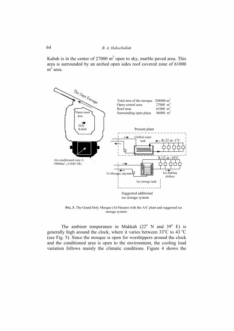
the mosque is 328000 m2 of which 120000 m2 is open area. The Mosque accommodates 730000 worshippers every prayer (5 times daily). The number rises to one million on weekends' prayer (Friday) and during special religion ceremonies. An extension plaza around the Mosque has been made to accommodate for 2 million worshippers during pilgrimage time. Air conditioning of the roof-covered area in the mosque presents a challenging engineering venture. To supply cold air to an area without side walls is a unique problem, where most of the cold air cannot be re-circulated. In addition, the large heat load generated by occupants while performing their prayers raises the capacity of the air conditioning machines. The A/C project is the second largest of its kind on earth, where special air manifolds, underground chilled water system extends from a central air conditioning plant 3 km from the site are designed and custom built. At present the capacity of the air conditioning system is 47000 kW (13440 TR). The system uses conventional water chillers, which comprises 32 DX type chillers (420 TR each) and each chiller has 4 York compressors. Fig. 3 shows a plan of the Holy Mosque where the
0 2 4 6 8 10 12 14 16 18 20 22 24
Load T
R
Chillers cover the load and charge the storage
charge
Storage tank disch
Hours Duration, hr
B. A. Habeebullah
64
Kabah is in the center of 27000 m2 open to sky, marble paved area. This area is surrounded by an arched open sides roof covered zone of 61000 m2 area.
FIG. 3. The Grand Holy Mosque (Al-Haram) with the A/C plant and suggested ice
storage system.
The ambient temperature in Makkah (22o N and 39o E) is generally high around the clock, where it varies between 33oC to 43 oC (see Fig. 5). Since the mosque is open for worshippers around the clock and the conditioned area is open to the environment, the cooling load variation follows mainly the climatic conditions. Figure 4 shows the
Suggested additional
ice storage system
Open inner
area
To Mosque, daytime
Ice storage tank
R-22 at -10oC
R-22 at -1oC
Chilled water
tank
Ice making
chillers
Holy
Kabah
Air-conditioned zone A
39000m2, (13440 TR)
Total area of the mosque 208000 m2
Open central area 27000 m2
Roof area 61000 m2
Surrounding open plaza 86000 m2
Present plant
Economic feasibility of thermal energy storage systems
65
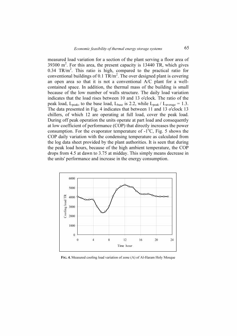
measured load variation for a section of the plant serving a floor area of 39300 m2. For this area, the present capacity is 13440 TR, which gives 0.34 TR/m2. This ratio is high, compared to the practical ratio for conventional buildings of 0.1 TR/m2. The over designed plant is covering an open area so that it is not a conventional A/C plant for a well-contained space. In addition, the thermal mass of the building is small because of the low number of walls structure. The daily load variation indicates that the load rises between 10 and 13 o'clock. The ratio of the peak load, Lpeak, to the base load, Lbase is 2.2, while Lpeak / Laverage = 1.3. The data presented in Fig. 4 indicates that between 11 and 13 o'clock 13 chillers, of which 12 are operating at full load, cover the peak load. During off peak operation the units operate at part load and consequently at low coefficient of performance (COP) that directly increases the power consumption. For the evaporator temperature of -1oC, Fig. 5 shows the COP daily variation with the condensing temperature as calculated from the log data sheet provided by the plant authorities. It is seen that during the peak load hours, because of the high ambient temperature, the COP drops from 4.5 at dawn to 3.75 at midday. This simply means decrease in the units' performance and increase in the energy consumption.
0
1000
2000
3000
4000
5000
6000
0 4 8 12 16 20 24
Time hour
Co
oli
ng
lo
ad
TR
FIG. 4. Measured cooling load variation of zone (A) of Al-Haram Holy Mosque

B. A. Habeebullah
66
0 2 4 6 8 10 12 14 16 18 20 22 24
20
24
28
32
36
40
44
48
3.5
3.75
4
4.25
4.5
4.75
5
Hours duration
Te
mp
era
ture
, o
C
COPa
Tc
To
COPa
Tc =T
o +15 T
e = -1
oC
FIG. 5. Hourly variation of COPa with condensing and ambient temperatures
for the DX chillers of Al-Haram plant
Based on the available data it is of interest to look for an energy storage option and operation schedule that provide the most economic cost function, Ctotal. For the present case, an ice storing technology is adapted and two scenarios are investigated in the following section.
5. Costing Scenarios
Scenario 1
5.1. Full load scheme
For full load storing, it is suggested to produce substantial amount of ice overnight to handle the entire peak load between 5:00 and 16:00 o'clock. In this proposed operation scenario, 25 chillers operate at
Economic feasibility of thermal energy storage systems
67
full load between 17 PM to 04 AM and an additional chiller operates for 1 hour at 6 AM as shown in Table 1. Some of these chillers are in operation as water chillers to provide the Holy Mosque with the necessary air conditioning load, where the other chillers charge the storage tanks (produce the required amount of ice) to be discharged between 5 AM and 16 PM. The present chillers control is set to provide chilled water at 5oC at evaporator temperature of -1oC. Using the same chillers to produce ice requires reduction of the evaporator temperature to -10 oC therefore, the ice making chillers' cooling capacity decreases below the 420 TR. The refrigeration cycle is solved for evaporator temperature of -10 oC with R-22 and the drop in capacity was found to be 13.5%. Therefore, a correction factor of 0.865 for the evaporating temperature change is used. In addition, storing energy in the form of ice passes through a freezing process where the rate of heat transfer is affected by the ice build up thickness. A factor of 0.75 is assumed for the ice formation process [7]. This makes an overall conversion factor of 0.649, which means that the chiller capacity when controlled to make ice reduces from 420 TR to 272.6 TR.
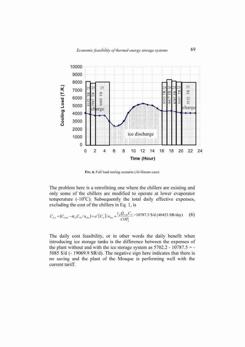
The total cooling load, which is the integrated area under the cooling curve, amounts to 97485TR-h, of which 49940 TR-h is the off-peak cooling load and the rest is stored in the ice tanks. Therefore, the plant is operated during night time only making use of the relatively low ambient temperature and high COP. The operation time schedule is given in Table 1, it indicates that only 25 chillers of the plant operate close to full load for 12 hours a day to handle the entire total cooling needs. The main advantage of the suggested scenario is the improved operation of the chillers all the time (average COPa = 4.2). The average COP is calculated as the mean of the variation shown in Fig. 5.
Let us investigate the economics of the proposed scenario where the chillers operate only for 12 hours at their rated capacity. In Saudi Arabia the electricity tariff is mainly a flat rate at 0.016 $/kWh (0.06 SR/ kWh) for low-level consumption up to 1000 kWh and increases to 0.07 $/kWh (0.26 SR/kWh) for higher consumption. The daily operational cost (the last term in Eq. 4) for normal operation without ice storage assuming the high electricity rate is
B. A. Habeebullah
68
dtECelel∫
24
0
= ( ) dtCCOPQ elaevap∫24
0
& = 5702.2 $/d
The daily operation cost of supplying the normal load and making ice during the 12 hours nighttime period is calculated in two parts using the data of Table 1 to give
( )
( ) 07.0420158
420107
chillersIce
chillersWater×
⎪⎪⎪
⎭
⎪⎪⎪
⎬
⎫
⎪⎪⎪
⎩
⎪⎪⎪
⎨
⎧
⎟⎠
⎞⎜⎝
⎛ ×××+××+××
+⎟⎠
⎞⎜⎝
⎛ ×××+××+××
444444444 3444444444 21
444444444 3444444444 21
4.2
3.51420141420163
4.2
3.5142011242093
=7325 $/d (27469 SR/d) (5)
The capital investment of the ice storage tank is determined by calculating the mass of ice formed during the 12 hours operation period that is necessary to provide 49590 TR-h (174,061 kW) (area marked charge in Fig. 6). Following the pricing data of Hasnain [5] for local market cost of 29.3 $/kWh (110 SR/ kWh, base year 1998) and assuming a 25% inflation rate that makes the installation cost 36.7 $/kWh (137.5 SR/kWh).
The capital investment for the storage tanks Cst is then, $ 6.38 million (23,933,374 SR).
Assuming an interest rate of 10% and 10 years payback period the capital
recovery factor c
a is 0.163. The capital investment annuity, A, is
A = st
c
Ca × = 1.039 Million $ (3,895,157 SR)
Assuming 300 working days per year, the storage capital contributes 3462.36 $/d (12984 SR/d) for the daily total investment repayment.
Economic feasibility of thermal energy storage systems
69
0
1000
2000
3000
4000
5000
6000
7000
8000
9000
10000
0 2 4 6 8 10 12 14 16 18 20 22 24
Time (Hour)
Co
oli
ng
Lo
ad
(T
.R.)
FIG. 6. Full load storing scenario (Al-Haram case)
The problem here is a retrofitting one where the chillers are existing and only some of the chillers are modified to operate at lower evaporator temperature (-10oC). Subsequently the total daily effective expenses, excluding the cost of the chillers in Eq. 1, is
[ ]a
elevapop
dayst
c
daychchtotalndCOP
CQtnCanCCC
&
+=−= /]/[,
α =10787.5 $/d (40453 SR/day) (6)
The daily cost feasibility, or in other words the daily benefit when introducing ice storage tanks is the difference between the expenses of the plant without and with the ice storage system as 5702.2 - 10787.5 = - 5085 $/d (- 19069.9 SR/d). The negative sign here indicates that there is no saving and the plant of the Mosque is performing well with the current tariff.
charge
25 25 258152 T
R
7987 T
R
8080 T
R
charge
26 25
8167 T
R
8152 T
R
8115 T
R
8417 T
R
8287 T
R
25 25 25
ice discharge

B. A. Habeebullah
70
TABLE 1. Scenario 1 Operation scheme for full load storage Al Haram Holy Mosque Plant
Scenario 1
Full load storage
Water Chiller Ice Chiller
Time
hours
Required
load,
TR
No. of
Chillers in
operation
TR
No. of
Chillers in
operation
TR
Storage
discharg
e TR
Total No. of
chillers in
operation
0
1
2
3
4
5
6
7
8
9
10
11
12
13
14
15
16
17
18
19
20
21
22
23
4065
3900
3720
3720
3720
3000
2400
2450
3000
4070
4800
5120
5290
5130
5040
4625
4330
4300
4330
4200
4080
4065
4065
4065
10
10
9
9
9
off
off
off
off
off
off
off
off
off
off
off
off
11
11
10
10
10
10
10
4200
4200
3780
3780
3780
off
off
off
off
off
off
off
off
off
off
off
off
4620
4620
4200
4200
4200
4200
4200
15
15
16
16
16
off
off
off
off
off
off
off
off
off
fof
off
off
14
15
15
15
15
15
15
4087*
4087
4360
4360
4360
off
off
off
off
off
off
off
off
off
off
off
off
3815
4087
4087
4087
4087
4087
4087
-
-
-
-
-
3000
2400
2450
3000
4070
4800
5120
5290
5130
5040
4625
4330
-
-
-
-
-
-
-
25
25
25
25
25
0
0
0
0
0
0
0
0
0
0
0
0
25
26
25
25
25
25
25
Total,
TR-h
97485 49980 49590 49255
* The chiller capacity is multiplied by correction factor (0.649) to convert the water chiller into ice chiller
Adapting a time dependent tariff to encourage savings is investigated. Assume a base tariff structure where the current low rate of 0.016 $/kWh is fixed as nighttime rate and the daytime rate is maintained

Economic feasibility of thermal energy storage systems
71
at its level of 0.07 $/kWh. In this case the daily cost of operation (replace 0.07 by 0.016 $/kWh in Eq. 5) is 1690.4 $/d.
The total daily effective cost Cd, n as in Eq. 6 becomes 5152.8 $/d
In this case the daily cost saving including the ice storage is 5702.2 - 5152.8 = 549.4 $/d
The above result is based on the suggested full load storage scenario and base tariff structure. In this scenario, the daily saving is 549.4 $/d, the storage capital cost will be paid in 10 years, afterwards the daily saving in operational cost will be 4011.76 $/d.
-6000
-5000
-4000
-3000
-2000
-1000
0
1000
2000
3000
4000
0 0.01 0.02 0.03 0.04 0.05
Nighttime rate $/kWh
Sav
ing
$/d
ay
0.3 $/kWh
0.26
0.2
nonprofit
Profitable
region
break even
point
Loss region
FIG. 7. Dependence of the daily savings on the tariff structure.
Figure 7 shows the saving for different nighttime rates, which indicates that the break-even point is 0.021 $/kWh (0.077 SR/kWh). As seen in the figure, selecting a daytime rate higher than this value would
B. A. Habeebullah
72
not achieve any savings. In addition the break-even point depends on the absolute value of the time rates. In principle, the daily saving is
⎥⎦
⎤⎢⎣
⎡⎟⎟⎠
⎞⎜⎜⎝
⎛⎟⎟⎠
⎞⎜⎜⎝
⎛⎟⎟⎠
⎞⎜⎜⎝
⎛+−=
oncontributi
tank storage icedaily
tariff(bep)pointevenbreak
with costoperationdaily
tariffrate flat with
costoperationdailysavingdaily
(7)
The break-even point is determined when the savings in Eq. 7 becomes zero. Changing the off-peak rate between 0.05 and 0.0.8 $/kWh changes the break-even point from 0.008 to 0.03 $/kWh, and consequently changes the saving zone as seen in Fig. 7. To that point, it is of interest to investigate a partial storage scenario and compare to that of the full storage mode.
Scenario 2
5.2. Partial load storing scheme
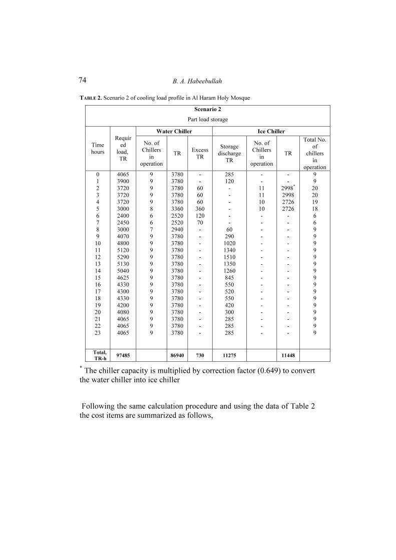
Inspection of the cooling load (Fig. 4) shows that the peak load falls between 9 AM to 4 PM, where the load reaches 5290 TR. For partial storing the peak load is leveled at 3780 TR so that the energy above this load is supplied from storage tanks. As in the case of full ice storage, some of the chillers operate at their design condition to produce chilled water and others make enough ice to cover the required energy (the shaded area in Fig. 8). The operation schedule of the cold-water chillers starts by operating 9 chillers at full load from 9 PM to 4 AM then shut down one chiller at 4 AM to cover a load of 3000TR. For the next two hours, only 6 chillers cover the 2500 TR load. At 8 AM, an additional chiller is started to raise the load to 2930 TR as shown in Table 2. The operation scenario covers the energy required below the selected level of 3780 TR; the extra loads are covered from the ice storage tank. For example at midnight the required load is 4065, the difference (285 TR) is provided by the ice storage tanks. The advantage of this arrangement is the operation of all water-chilling units at their full load with maximum COP. The ice is built up between 1 AM and 5 AM by operating 11 ice making units for 2 hours then continue for another two hours by 10 units as shown in Table 2 column # 8. The energy stored

Economic feasibility of thermal energy storage systems
73
during this period is 11448 TR-h while the required energy during the discharge period is 11275 TR-h. Adjusting the control of only one ice-making unit to have a shorter ice-charging period can correct for this difference. Table 2 shows the detailed operation scheme for partial storage scenario.
0
1000
2000
3000
4000
5000
6000
0 2 4 6 8 10 12 14 16 18 20 22 24
Hours duration
Lo
ad
T.R
.
FIG. 8. Partial load storing scenario
Let us investigate the cost for the proposed partial load-storing scenario, where the ice chillers operate only for 4 hours, 1-5 AM, at their rated capacity and average COPa. Noting that the average actual COPa is 4.38 for the time between 1 AM-5 AM and 4.01 between 10 AM and 1 PM as estimated from Fig. 5.
11 c
hil
lers
10 c
hil
lers
chillers
Ice discharge
Ice
stora
ge
chil
lers
B. A. Habeebullah
74
TABLE 2. Scenario 2 of cooling load profile in Al Haram Holy Mosque
Scenario 2
Part load storage
Water Chiller Ice Chiller
Time
hours
Requir
ed
load,
TR
No. of
Chillers
in
operation
TR Excess
TR
Storage
discharge
TR
No. of
Chillers
in
operation
TR
Total No.
of
chillers
in
operation
0
1
2
3
4
5
6
7
8
9
10
11
12
13
14
15
16
17
18
19
20
21
22
23
4065
3900
3720
3720
3720
3000
2400
2450
3000
4070
4800
5120
5290
5130
5040
4625
4330
4300
4330
4200
4080
4065
4065
4065
9
9
9
9
9
8
6
6
7
9
9
9
9
9
9
9
9
9
9
9
9
9
9
9
3780
3780
3780
3780
3780
3360
2520
2520
2940
3780
3780
3780
3780
3780
3780
3780
3780
3780
3780
3780
3780
3780
3780
3780
-
-
60
60
60
360
120
70
-
-
-
-
-
-
-
-
-
-
-
-
-
-
-
-
285
120
-
-
-
-
-
-
60
290
1020
1340
1510
1350
1260
845
550
520
550
420
300
285
285
285
-
-
11
11
10
10
-
-
-
-
-
-
-
-
-
-
-
-
-
-
-
-
-
-
-
-
2998*
2998
2726
2726
-
-
-
-
-
-
-
-
-
-
-
-
-
-
-
-
-
-
9
9
20
20
19
18
6
6
9
9
9
9
9
9
9
9
9
9
9
9
9
9
9
9
Total,
TR-h 97485 86940 730 11275 11448
* The chiller capacity is multiplied by correction factor (0.649) to convert the water chiller into ice chiller
Following the same calculation procedure and using the data of Table 2 the cost items are summarized as follows,

Economic feasibility of thermal energy storage systems
75
a- Operation cost for the total cooling load, 97484 TR-h at a daily average COP of 4.2 and 0.07 $/kWh
5702.2 $/d
b- Operation cost for the water chillers producing 86940 TR-h at an average COP of 4.2 at 0.07 $/kWh
5086 $/d
c- Operation cost during ice making period at 0.07 $/kWh and COPa of 4.38 (column # 8, Table 2)
980 $/d
d- ic Ice storage capital to form 11448 TR-h equivalence of ice in 4 h
(10046 kWh storage) at 36.7 $/kWh
368,353 $
e- Fixed charges rate for the ice storage capital (300 working days/y and 0.16275 fixed charges rate)
200 $/d
f- Total daily cost with ice storage nd
C,
= b + c
+ e
6266 $/d
g- Net daily benefit (a – f) -563.8 $/d
Here again, the negative sign means that there is no saving with the partial storage scenario. The reason is the constant electricity rate imposed by the authorities. If the tariff strategy is applied, and an attractive rate of 0.016 $/kWh is enforced during nighttime (8 AM -8 PM), then the daily ice making cost becomes 226 $/d instead of 980 $/d. For this case, the operation cost for the water chillers changes because of the reduced rate at night to become 3187 $/d. The cost of operation for the chillers without ice storage (item a above) drops by benefiting from the low nighttime rate to be 3776.6 $/d.

B. A. Habeebullah
76
h- Operation cost for the total cooling load, 97484 TR-h at 0.016 $/kWh from 8 PM to 8 AM and 0.07 for the day time with daily average COP of 4.2
3776.6
$/d
i- The net daily benefit is then [ h – (226 + 3187 + 200)]
163 $/d
As can be seen from the above values, the operating cost of using the ice storage system with base tariff strategy is cheaper than the conventional system. The ice storage investment will be paid back after 10 years, otherwise it is impractical. The saving for the first 10 years is 163 $/d, while the net daily saving afterwards will be 363 $/d. Both numbers are not encouraging to implement a partial load storing strategy.
The net daily benefit of applying the partial load storing is much less than that for full load storing, nearly 30%. This indicates that because of the special variation of the cooling load of the Holy Mosque and the abnormal features of the building, the partial load storage is not attractive.
6. Conclusions
This study investigated the potential of installing a thermal energy storage system to the air conditioning plant of a special religious building with unique cooling demand. The Grand Holy Mosque building is the largest religious building on earth and of distinctive features where the large air-conditioned floor area is roof covered and has no walls; it is open to the atmosphere. The worshippers' traffic is in bulk five times daily and demands high cooling load. In addition, hundreds of thousands of worshippers attend the sacred weekend ceremony, which takes place at noontime of maximum ambient temperature. The economic analysis
Economic feasibility of thermal energy storage systems
77
combines the effects of active energy storage system and a time-structured tariff on the daily utility bill.
The results based on measured cooling load and ambient temperature showed that with the current subsidized electricity rate of 0.07 $/kWh there is no gain in introducing ice storage system neither for full nor partial load scenarios. Combined utilization of an incentive tariff model and storing technology showed reasonable daily savings for full load storing scheme. Savings out of partial load storing were not attractive even with the structured base tariff (0.016 $/kWh for night operation and 0.07 $/kWh for peak period operation). The break even daytime electricity tariff was determined for different conditions.
Acknowledgements
The author gratefully acknowledges the financial support of this work by King Abdulaziz University Research Center, Jeddah, Saudi Arabia under contract No. 108/424.
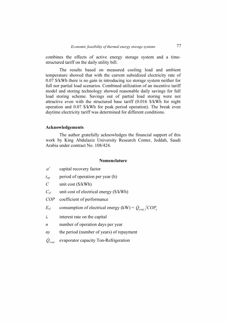
Nomenclature
c
a capital recovery factor
top period of operation per year (h)
C unit cost ($/kWh)
Cel unit cost of electrical energy ($/kWh)
COP coefficient of performance
Eel consumption of electrical energy (kW) = aevap
COPQ&
ir interest rate on the capital
n number of operation days per year
ny the period (number of years) of repayment
evapQ& evaporator capacity Ton-Refrigeration

B. A. Habeebullah
78
Subscripts
a average ch chiller el electricity st storage
References
[1] Lehman, T., Jones, D. D. and Vogel D. R., Off-peak HVAC is once again hot, J.
Consulting Specifying Eng., pp 46-49, Nov. 2001.
[2] ASHRAE, Thermal Energy Storage, ASHRAE Handbook of applications, American
society of heating ventilation and air conditioning, Atlanta Georgia, (1995).
[3] Zhou, G., Krarti, M. and Henze, G. P., Parametric analysis of active and passive
building thermal storage utilization, ASME J. Solar Engineering, 127, pp 37-64, (2005).
[4] AlHazmy, M. and Najjar, Y. S., Augmentation of gas turbine performance using air
coolers, Applied thermal engineering, 24, pp 415-429, (2004).
[5] Hasnain, S. M., Alawaji, S. H., Al-Ibrahim, A. M. and Smiai, M. S., Prospects of cool
thermal storage utilization in Saudi Arabia, Energy Conversion & Management, 41, pp
1829-1839, (2000).
[6] Hasnain, S. M. and Alabbadi, N. M., Need for thermal energy storage in Saudi Arabia,
Applied Energy, 65, pp 153-164, (2000).
[7] Baltimor aircoil, Ice chiller thermal storage unit, TSU references, TSU-M.xis document,
(1999).
[8] Michael, H. D., Ice thermal storage for Colorado School, ASHRAE Journal, 45, 5, pp 50-
53, (2003).
[9] Maurer L., Thermal storage does justice to Miami court of appeals, Engineered Systems
17, issue 2, pp 20-22, (2000).
[10] NAICS/Industry Contractors, Shifting to ice storage triples campus’ cooling capacity,
Engineered Systems 17, 7, pp 3-6, (2000).
[11] Keisuke, O., Thermal storage air conditioning system in subway station building,
Japanese Railway Engineering, 148, pp 17-20, (2002).
[12] Collins, T., Parker, S. A. and Brown, D., Thermal Energy Storage for Space Cooling
Technical report produced for the U.S. Department of Energy by the Pacific Northwest
National Laboratory, December 2000.

Economic feasibility of thermal energy storage systems
79
[13] Gopal, P. M., Raba'a, A. A., Al-Hadban, Y. N. and Sebzali, M. J. Energy efficient and
cool storage assisted air-conditioning system for hospital building, ASME, Advanced
Energy Systems Division, AES, 40, pp 481-487, (2000).
[14] Lawrence, S. and Rudin, A., Design for the future by looking at the past, HVAC
Heating, Piping, Air Conditioning, 69, 11, pp 68-75, (1997).
[15] Chen, S. L., Jwo, C. S., Yang, B. S. and Yen, J. Y., Theoretical and experimental
Investigations of a packed ice-storage air conditioning system, J. of Chinese Society of
Mechanical Engineers, Vol 18, No. 5, pp 445-456, (1997).
[16] Silver, S. C., Milbutz, A., Jones, J. W., Peterson, J. L. and Hunn, B. D., Component
models for computer simulation of ice storage systems, ASHRAE Transactions, 95 (1), pp
1214-1226, (1989).
[17] Vick, B., Nelson, J. D. and Yu, X., Model of an ice-on-pipe brine thermal storage
component, ASHRAE Transactions, 102, 1, pp 45-54, (1996).
[18] Jones, J. W. and Shiddapur, G. S., Evaluation of RP 459 algorithms for modeling
external melt, ice-on–pipe thermal ice storage system components, ASHRAE Trans., 101,
2, pp 1342-1351, (1995).
[19] Neto J. H. and Krarti M., Deterministic model for internal melt ice on coil thermal
storage tank, ASHRAE Trans., 103, 1, pp. 113-124, (1997).
[20] Kawada, A., Ishii, M. and Abiru, K., Development of large capacity ice storage system,
Mitsubishi Heavy Industries, 35, No. 3, Oct. 1998.
[21] West, J. and Braun, J. E., Modeling partial charging and discharging of area-constrained
ice storage tank, HVAC & Research, 5, July 1999.
[22] Saito A., Recent advances in research on cold thermal energy storage: Review, Int. J.
Refrigeration, 25, pp 177-189, (2002).
[23] Dorgan, C. E. and Elleson, J. S., Design guide for cool thermal storage, American
Society of Heating Refrigeration and Air-Conditioning Engineering, Atlanta, (1993).
[24] McCullough, J. M., Ice thermal storage: system selection and design, Consulting,
specifying engineer, 3, 1, pp. 70-77, (1988).
[25] Musgrove, A. R., Ehmek, H. J. and Stocks, K. J., Optimum design and operation of ice
storage air conditioning systems under Australian TOU tariffs, Energy, 14, 9, pp. 525-
535, (1989).
[26] Hongxing, Y. and Shijun, Y., Partial ice storage: Application to air conditioning systems
in Hong Kong, Building Services Engineering Research and Technology, 20, 4, pp. 201-
203, (1999).
[27] Henze, G. P. and Krarti, M., Ice Storage System controls for the reduction of operating
cost and energy use, Joint Center of Energy Management, Univ. of Colorado, (1998).
[28] Henze G. P. and Krarti M., Simulation environment for analysis of ice storage controls,
Joint Center of Energy Management, University of Colorado, (1997).

B. A. Habeebullah
80
[29] Ihm, P., Krarti, M. and Henze G. P., Development of a thermal energy storage model
for Energy Plus, Energy and Buildings, 36, pp 807-814, (2004).
[30] http://www.eren.doe.gov/buildings/energy_tools/energyplus, EnergyPlus v1.0.1, program
DOE, (2002).
[31] Henze, G. P., Krarti, M. and Brandemuehl, M. J., Guidelines for improved
performance of ice storage systems, Energy and Buildings, 35, pp 111-127, (2003).

Economic feasibility of thermal energy storage systems
81
�������� ���� ��� � ���� �������� ������ : ����
����������� ������ ���!� �
� .�� ���� ��
������� ����� �� ��� ���� ������ �� � �� ����� ������� �� �
������� � ���� ����� ��� ����� ����� ��� ����� ������
��� � ������� ���� !" ��#������� ��� ���" !" �$�$% &���
����'�� ��" !" ��� ()� !��� � *������� !���� �+���,� . �
�#������� ���-� ����� ��� /0%���� �+���,� ����" 1�2
"�3��� ���4 5#��6 ���$2 7��� �� �#������� � ������ 840�
�� �� �+���,� !" 9����� ������ �4%� ���)� 9��%�� .��� 8�: ;�
� <����� 4�% 9�'� *��� ��� ����$��,� =����� ������
*������ &����� ���� *������� �+���, ���4 �"�3� >������
����� �� !" 9����� ?� ���� �3�����) !�" !���� ��3 9%A�
9��3�� .( 9���� 1�� C#�$% 2 !�" ����" � >��� ������

B. A. Habeebullah
82
� � 9���� �0���� ������ !������ ��)� !��393009 2 !�:
����� �D�� ��$�� � �� !���%�� ���� ����0 ����
9���� !" ��� E% . &,F� ��# �A�� �3��� 9�� !" �
����4 1��2 <�G�� � ���'�� ��" !" �3��� +$ ��$��
!#������� ���� 1�� H���� . I�" J<��$��,� ������� ���
����" A��� � ������� ����� ��%��� �� !���� �+���,�
�4�%� 9��'� *��� !" �K���� ���� E�� � ��L6��� &���$
!��K . ��L6��� �������� ������ !���� ��L6��� &���$ �6�
� ��L6���� ����� ��� � �"�3��� 9�'� ���" �%�� !��� � �����
�KG ���3� ���� ���� ���� . �� 9� E�� ������� ��3 H�
�:���) ���� ����� ����10 % ����� �������� ���0� �10
����� .!#4� �� ��� �4%� 9�'� 1�� ������� 7���� 9� ��.
������� N#��� ��A�� 9�'� *��� ����$��� �#�" ���: E�� O��
*��A !�" !#4��� �� ����� �4%��� P���� *��� !��K 4%
���6 ���� !#�������� �+����+� ����K � )0.07$ / ��������
���� .( !��4 9��'� *�6�2 � ������ �4%� �� (��� ���� !"
�#������� �"�3��� 40�� !" ��)3 ��"�� 1�� ��$��� �� O�I"
Economic feasibility of thermal energy storage systems
83
������ ����0�� . ������ �+����� �"�3�� O�I" ��K�� ���� 1�3"
�:���)0.07$ / � ����� ��L6��� ��� !" ���� �������0.016
$/ 8���) ���"�� I" ����� ����� ��S !" ���� �������549.4
$/ ����� �4%��� 9�'�� O��� ��$��� �� 9�� . ��� O�� ��
!�" ������ �4%��� 9�'� *�6�2 !" T�"��� ���� E�� �������
��"10 ��� �3� � ����� ��L6��� �0��� !" !���� �"��� 5�$�
�:4011.76$ /9��.
H���� 9�� �� !#������� �+���+� �0��% ��0��3� �6��� 9�
����3��� !����� �+���,� �"�3�) ��� U������0.008 � 0.03
$/ ���� ������� .( �������� I�" !#4��� �4%��� 9�'�� �������
����� 8��� <�� ��S O�V� ��A�� ���: �"��� ��� � >�� �
��:� <� ��S 9�'���.