Embed Size (px)
Citation preview
Data sheet
Eco-Damper ICD damper, ICC Check valve and ICS control valve
© Danfoss | DCS (ms) | 2019.07 AI310433586905en-000101 | 1
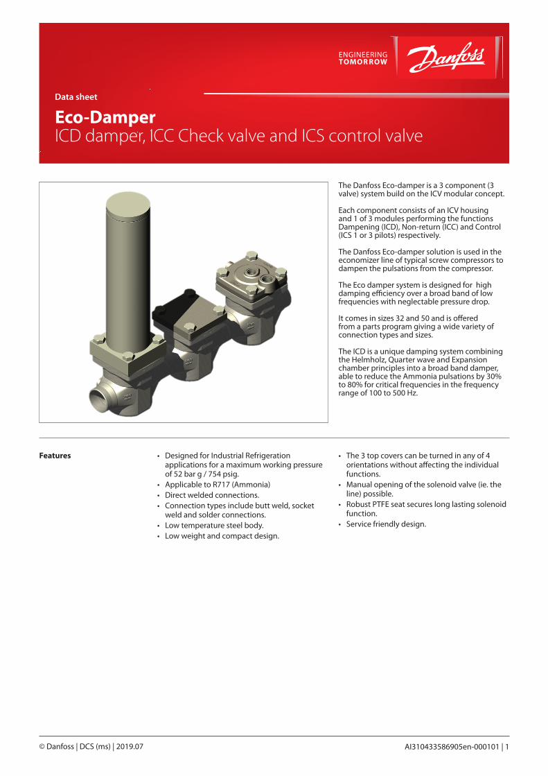
The Danfoss Eco-damper is a 3 component (3 valve) system build on the ICV modular concept.
Each component consists of an ICV housing and 1 of 3 modules performing the functions Dampening (ICD), Non-return (ICC) and Control (ICS 1 or 3 pilots) respectively.
The Danfoss Eco-damper solution is used in the economizer line of typical screw compressors to dampen the pulsations from the compressor.
The Eco damper system is designed for high damping efficiency over a broad band of low frequencies with neglectable pressure drop.
It comes in sizes 32 and 50 and is offered from a parts program giving a wide variety of connection types and sizes.
The ICD is a unique damping system combining the Helmholz, Quarter wave and Expansion chamber principles into a broad band damper, able to reduce the Ammonia pulsations by 30% to 80% for critical frequencies in the frequency range of 100 to 500 Hz.
• Designed for Industrial Refrigeration applications for a maximum working pressure of 52 bar g / 754 psig.
• Applicable to R717 (Ammonia)• Direct welded connections. • Connection types include butt weld, socket
weld and solder connections.• Low temperature steel body.• Low weight and compact design.
• The 3 top covers can be turned in any of 4 orientations without affecting the individual functions.
• Manual opening of the solenoid valve (ie. the line) possible.
• Robust PTFE seat secures long lasting solenoid function.
• Service friendly design.
Features
Data sheet | Eco-Damper, ICD damper, ICC Check valve and ICS control valve
© Danfoss | DCS (ms) | 2019.072 | AI310433586905en-000101
Contents Page
Features . . . . . . . . . . . . . . . . . . . . . . . . . . . . . . . . . . . . . . . . . . . . . . . . . . . . . . . . . . . . . . . . . . . . . . . . . . . . . . . . . . . . . . . . . . . . . . . . . .1
The Eco-Damper concept . . . . . . . . . . . . . . . . . . . . . . . . . . . . . . . . . . . . . . . . . . . . . . . . . . . . . . . . . . . . . . . . . . . . . . . . . . . . . . . . .3
Design (valve) . . . . . . . . . . . . . . . . . . . . . . . . . . . . . . . . . . . . . . . . . . . . . . . . . . . . . . . . . . . . . . . . . . . . . . . . . . . . . . . . . . . . . . . . . . . . .3
Technical data . . . . . . . . . . . . . . . . . . . . . . . . . . . . . . . . . . . . . . . . . . . . . . . . . . . . . . . . . . . . . . . . . . . . . . . . . . . . . . . . . . . . . . . . . . . . .3
Approvals . . . . . . . . . . . . . . . . . . . . . . . . . . . . . . . . . . . . . . . . . . . . . . . . . . . . . . . . . . . . . . . . . . . . . . . . . . . . . . . . . . . . . . . . . . . . . . . . .3
Function . . . . . . . . . . . . . . . . . . . . . . . . . . . . . . . . . . . . . . . . . . . . . . . . . . . . . . . . . . . . . . . . . . . . . . . . . . . . . . . . . . . . . . . . . . . . . . . . . .4
Selection . . . . . . . . . . . . . . . . . . . . . . . . . . . . . . . . . . . . . . . . . . . . . . . . . . . . . . . . . . . . . . . . . . . . . . . . . . . . . . . . . . . . . . . . . . . . . . . . . .5
Capacity . . . . . . . . . . . . . . . . . . . . . . . . . . . . . . . . . . . . . . . . . . . . . . . . . . . . . . . . . . . . . . . . . . . . . . . . . . . . . . . . . . . . . . . . . . . . . . . . . .5
Material specification . . . . . . . . . . . . . . . . . . . . . . . . . . . . . . . . . . . . . . . . . . . . . . . . . . . . . . . . . . . . . . . . . . . . . . . . . . . . . . . . . . . . .6
Ordering . . . . . . . . . . . . . . . . . . . . . . . . . . . . . . . . . . . . . . . . . . . . . . . . . . . . . . . . . . . . . . . . . . . . . . . . . . . . . . . . . . . . . . . . . . . . . . . . . .7
Dimensions . . . . . . . . . . . . . . . . . . . . . . . . . . . . . . . . . . . . . . . . . . . . . . . . . . . . . . . . . . . . . . . . . . . . . . . . . . . . . . . . . . . . . . . . . . . . . . .9
Data sheet | Eco-Damper, ICD damper, ICC Check valve and ICS control valve
© Danfoss | DCS (ms) | 2019.07 AI310433586905en-000101 | 3
The Eco-Damper concept is developed to highest flexibility of direct welded connections. For valve sizes ICV 32 and 50 a wide range of connection sizes and types is available.
The Eco-Damper concept
• There are two valve bodies available
ICV 32 ICV 50
D A SOC SD SA
Butt-weld DIN Butt-weld ANSI Socket weld ANSI Solder DIN Solder ANSI
The direct welded (non-flanged) connections secures low risk of leakage.
Design (valve) Connections There is a wide range of connection types available:• D: Butt weld, EN 10220 • A: Butt weld, ANSI (B 36.10)• SOC: Socket weld, ANSI (B 16.11)• SD: Solder connection, EN 1254-1• SA: Solder connection, ANSI (B 16.22)
The Eco-Damper valves are approved in accordance with the European standard specified in the Pressure Equipment Directive and are CE marked.For further details / restrictions - see Installation Instruction.
Valve body and top cover material Low temperature steel
ApprovalsThe ICV valve concept is designed to fulfil global refrigeration requirements.
ICD, ICC and ICS valves
Nominal bore DN 32 - 50 (11/4 - 2 in.)
Classified for Fluid group I
Category II
The individual components are CE, CRN and UL approved. For specific approval information, please contact Danfoss.
Technical data • Refrigerants Applicable to R717 (Ammonia)
• Temperature range: Media: -60 – 120 °C / -76 – 248 °F.
• Pressure The valve is designed for a max. working pressure of 52 bar g / 754 psi g
• Surface protection For excellent corrosion protection all valve outer surfaces are zinc-chromated. The Damper module is painted.
• Min. opening pressure differential: For fully opening of the ICS and ICC valves a pressure difference across the valves are required: ICS: 0.2 bar (2.9 psi) ICC: 0.1 bar (1.5 psi)
• Coil requirement for ICS+EVM Coils to be IP67.
• Damping frequency range 100 – 500Hz
Size 32 Size 50
Kv (m3/h) 17 44
Cv (USgal/min) 20 51
Data sheet | Eco-Damper, ICD damper, ICC Check valve and ICS control valve
© Danfoss | DCS (ms) | 2019.074 | AI310433586905en-000101
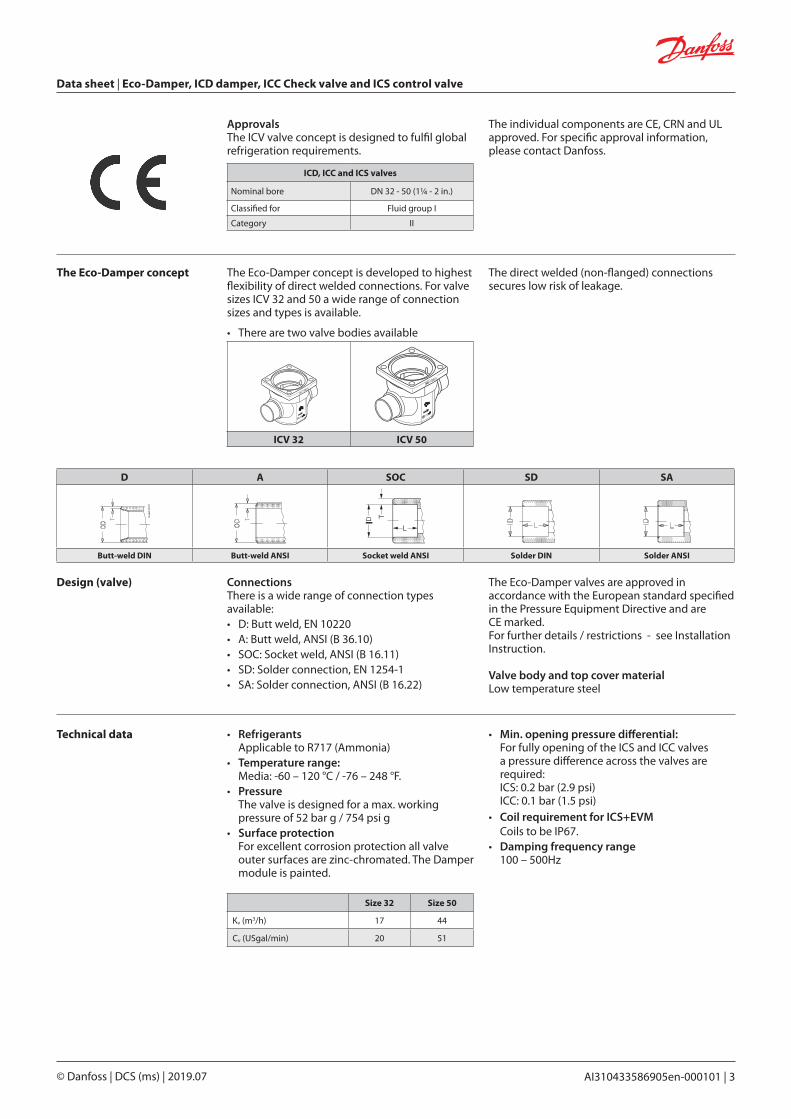
Though the refrigerant flow in the economizer line is towards the compressor, the pulsations moves in the opposite direction. Due to this phenomenon the sequence of the 3 components is important. Seen from the compressor the dampening comes first followed by flow alignment and flow control.
It is equally important to orientate the valve housings with the arrow pointing in the mass flow direction (pointing towards the compressor).
Distances between the single components are of great importance and recommendations should be followed.
The Eco damper is designed for high efficiency dampening of pulsation pressure peeks and creating unidirectional flow in economizer lines of Ammonia systems.
Depending on the RPM’s and geometry of the typical screw compressor the frequency and amplitude of the pulsations in the economizer lines will vary.
The ICD damper is specifically designed for dampening of the critical Ammonia pulsations in the broad band of 100 to 500 Hz.
A simple calculation will clarify if a certain compressor set-up will result in pulsation frequencies between 100 and 500 Hz and this clarification should be made before considering the Eco damper solution. Please look into the Selection section.
Function The ICD is a unique damping system combining the Helmholz, Quarter wave and Expansion chamber principles into a broad band damper, able to reduce the Ammonia pulsations by 30% to 80% for critical frequencies in the specified frequency band
The ICC non-return/check valve is a robust valve optimized to withstand pulsations in the same low frequency band. The ICC features the ability to reduce small pulsating movements in the wrong direction with an overall low pressure drop for the main flow direction.
The ICS control valve is the ordinary valve used for allround control purposes. In the Eco-Damper application the 3 pilot version is offered to be able to include more functions like solenoid and/or pressure control. The solenoid function is the on/off function for the entire Eco-Damper.
The Eco-Damper must be assembled like shown in the above figure with the ICD next to the compressor followed by the ICC and finally the ICS.
To achieve the optimum dampening effect and avoid vibrations it is important to secure the internal distances between the different components (see above figure).
For an appropriate support of the ICD, a tailored clamp suspension (A) is included in the ICD box. The supports B are also required for reducing vibrations and must be prepared and installed at site.
Max. 150 mm(5.9 in.)
Max. 150 mm(5.9 in.)
ICD
ICC
ICS
200-
300
mm
(8-1
2 in
.)
A
Compressor
Max. 150 mm(5.9 in.)
Mass flow direction
Pulsation direction
B B
Data sheet | Eco-Damper, ICD damper, ICC Check valve and ICS control valve
© Danfoss | DCS (ms) | 2019.07 AI310433586905en-000101 | 5
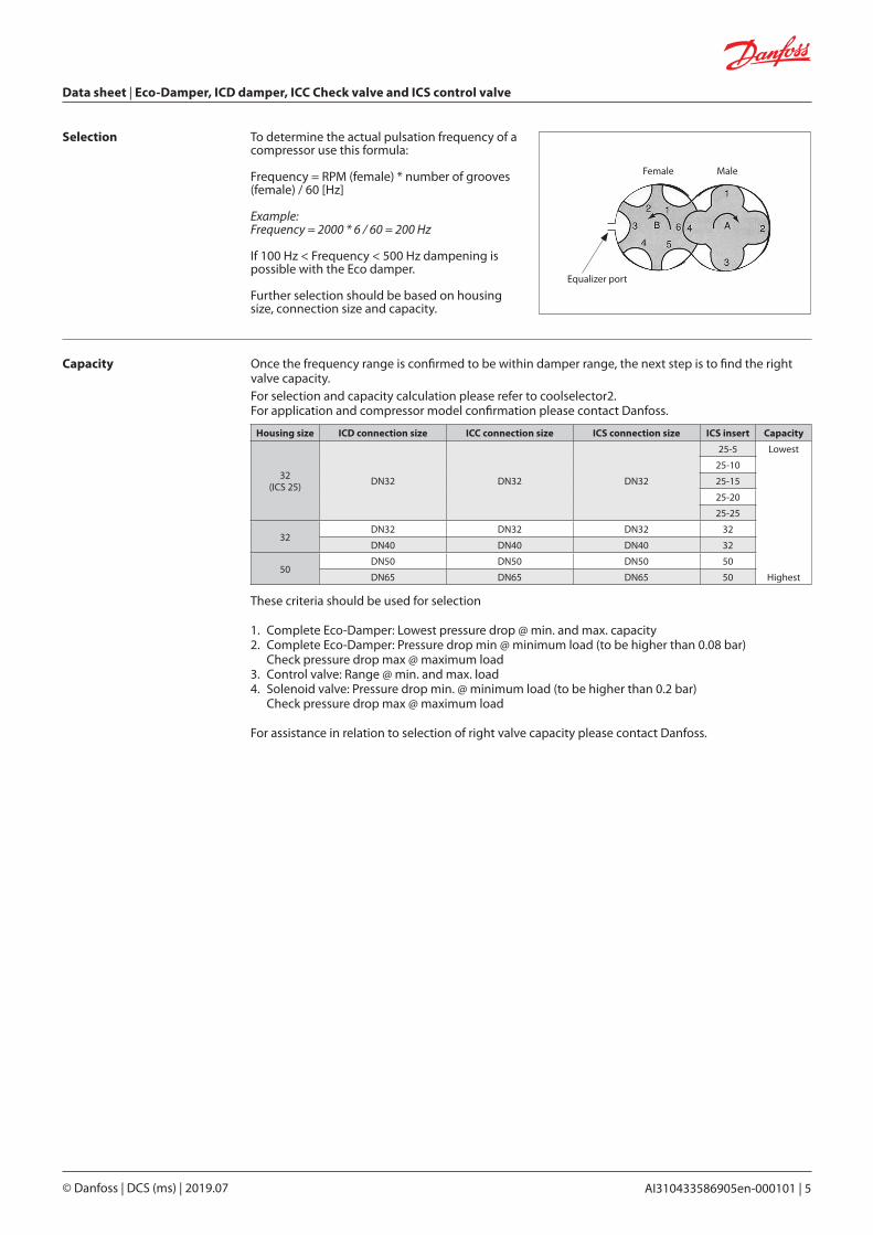
Selection To determine the actual pulsation frequency of a compressor use this formula:
Frequency = RPM (female) * number of grooves (female) / 60 [Hz]
Example:Frequency = 2000 * 6 / 60 = 200 Hz
If 100 Hz < Frequency < 500 Hz dampening is possible with the Eco damper.
Further selection should be based on housing size, connection size and capacity.
Equalizer port
Female Male
Capacity Once the frequency range is confirmed to be within damper range, the next step is to find the right valve capacity.For selection and capacity calculation please refer to coolselector2. For application and compressor model confirmation please contact Danfoss.
Housing size ICD connection size ICC connection size ICS connection size ICS insert Capacity
32(ICS 25)
DN32 DN32 DN32
25-5 Lowest
25-10
25-15
25-20
25-25
32DN32 DN32 DN32 32
DN40 DN40 DN40 32
50DN50 DN50 DN50 50
DN65 DN65 DN65 50 Highest
These criteria should be used for selection
1. Complete Eco-Damper: Lowest pressure drop @ min. and max. capacity2. Complete Eco-Damper: Pressure drop min @ minimum load (to be higher than 0.08 bar) Check pressure drop max @ maximum load 3. Control valve: Range @ min. and max. load 4. Solenoid valve: Pressure drop min. @ minimum load (to be higher than 0.2 bar) Check pressure drop max @ maximum load
For assistance in relation to selection of right valve capacity please contact Danfoss.
Data sheet | Eco-Damper, ICD damper, ICC Check valve and ICS control valve
© Danfoss | DCS (ms) | 2019.076 | AI310433586905en-000101
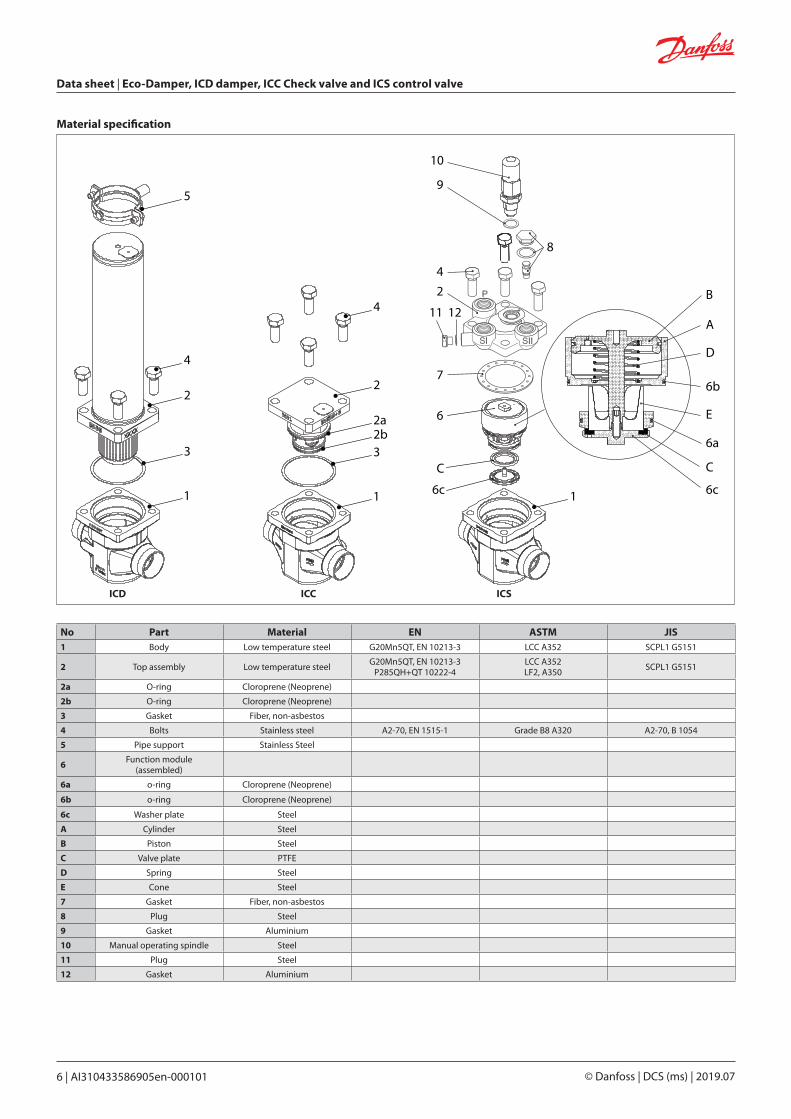
Material specification
No Part Material EN ASTM JIS1 Body Low temperature steel G20Mn5QT, EN 10213-3 LCC A352 SCPL1 G5151
2 Top assembly Low temperature steelG20Mn5QT, EN 10213-3
P285QH+QT 10222-4LCC A352LF2, A350
SCPL1 G5151
2a O-ring Cloroprene (Neoprene)
2b O-ring Cloroprene (Neoprene)
3 Gasket Fiber, non-asbestos
4 Bolts Stainless steel A2-70, EN 1515-1 Grade B8 A320 A2-70, B 1054
5 Pipe support Stainless Steel
6 Function module(assembled)
6a o-ring Cloroprene (Neoprene)
6b o-ring Cloroprene (Neoprene)
6c Washer plate Steel
A Cylinder Steel
B Piston Steel
C Valve plate PTFE
D Spring Steel
E Cone Steel
7 Gasket Fiber, non-asbestos
8 Plug Steel
9 Gasket Aluminium
10 Manual operating spindle Steel
11 Plug Steel
12 Gasket Aluminium
1
3
2
4
5
1
32b2a
2
4
6c
C
6
7
11 12
24
8
9
10
6c
C
6a
6b
D
E
A
B
1
ICD ICC ICS
Data sheet | Eco-Damper, ICD damper, ICC Check valve and ICS control valve
© Danfoss | DCS (ms) | 2019.07 AI310433586905en-000101 | 7
Ordering from the parts programme
Description Code Number
ICS 32 027H3200 *)
*) Including gasket and O-rings
ICS 1 ICS 3
Description Code Number
Top cover 1 Pilot 027H3172 *)
Top cover 3 Pilots 027H3173 **)
*) Including bolts**) including bolts and one blanking plug
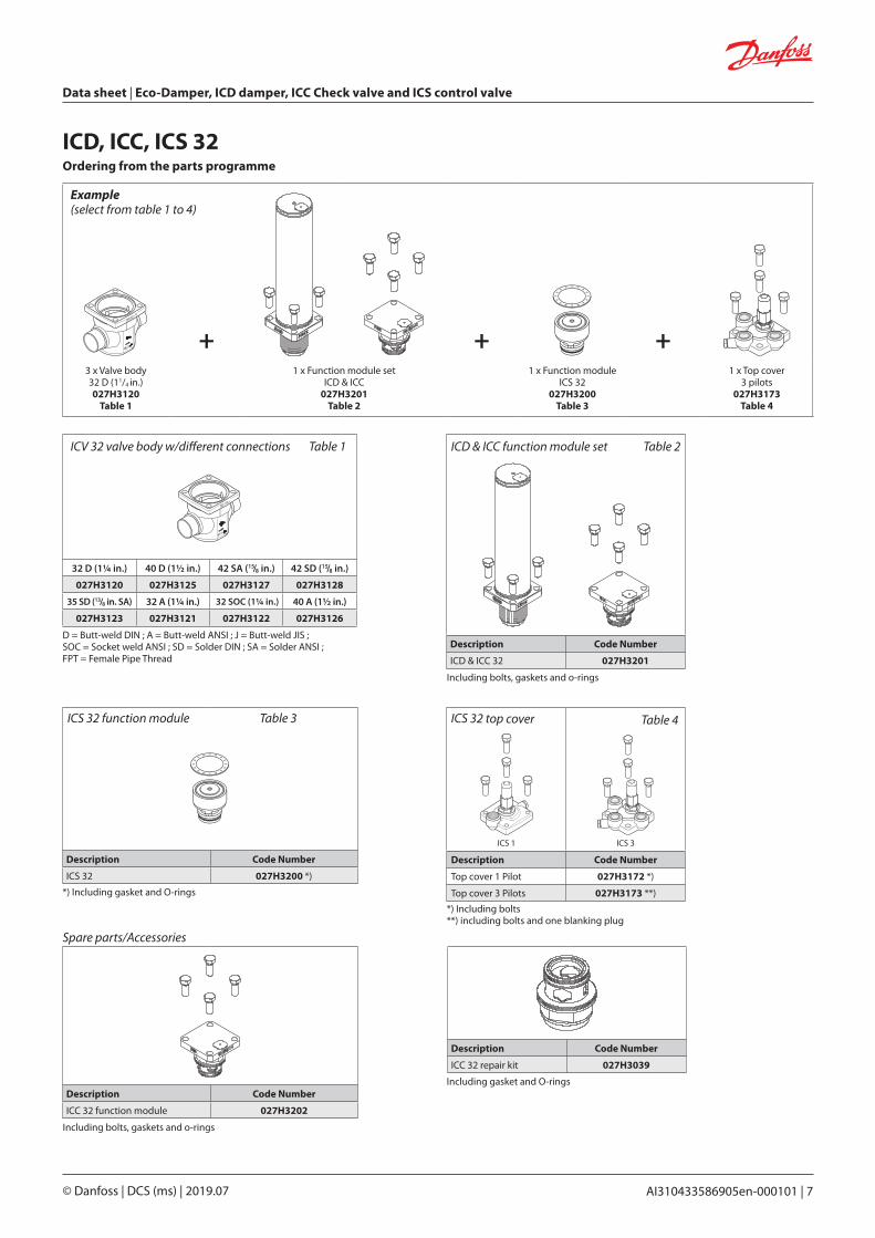
ICD, ICC, ICS 32
32 D (11/4 in.) 40 D (11/2 in.) 42 SA (15/8 in.) 42 SD (15/8 in.)
027H3120 027H3125 027H3127 027H3128
35 SD (13/8 in. SA) 32 A (11/4 in.) 32 SOC (11/4 in.) 40 A (11/2 in.)
027H3123 027H3121 027H3122 027H3126
+ + +3 x Valve body 32 D (11/4 in.)027H3120
Table 1
1 x Function module set ICD & ICC
027H3201Table 2
1 x Function module ICS 32
027H3200Table 3
1 x Top cover 3 pilots
027H3173Table 4
Example (select from table 1 to 4)
D = Butt-weld DIN ; A = Butt-weld ANSI ; J = Butt-weld JIS ; SOC = Socket weld ANSI ; SD = Solder DIN ; SA = Solder ANSI ; FPT = Female Pipe Thread
ICS 32 function module Table 3 ICS 32 top cover Table 4
ICV 32 valve body w/different connections Table 1
Description Code Number
ICD & ICC 32 027H3201
Including bolts, gaskets and o-rings
ICD & ICC function module set Table 2
Description Code Number
ICC 32 repair kit 027H3039
Including gasket and O-rings
Spare parts/Accessories
Description Code Number
ICC 32 function module 027H3202
Including bolts, gaskets and o-rings
Data sheet | Eco-Damper, ICD damper, ICC Check valve and ICS control valve
© Danfoss | DCS (ms) | 2019.078 | AI310433586905en-000101
Ordering from the parts programme
Description Code Number
ICS 50 027H5200 *)
*) Including gasket and O-rings
ICS 1 ICS 3
Description Code Number
Top cover 1 Pilot 027H5172 *)
Top cover 3 Pilots 027H5173 **)
*) Including bolts**) including bolts and one blanking plug
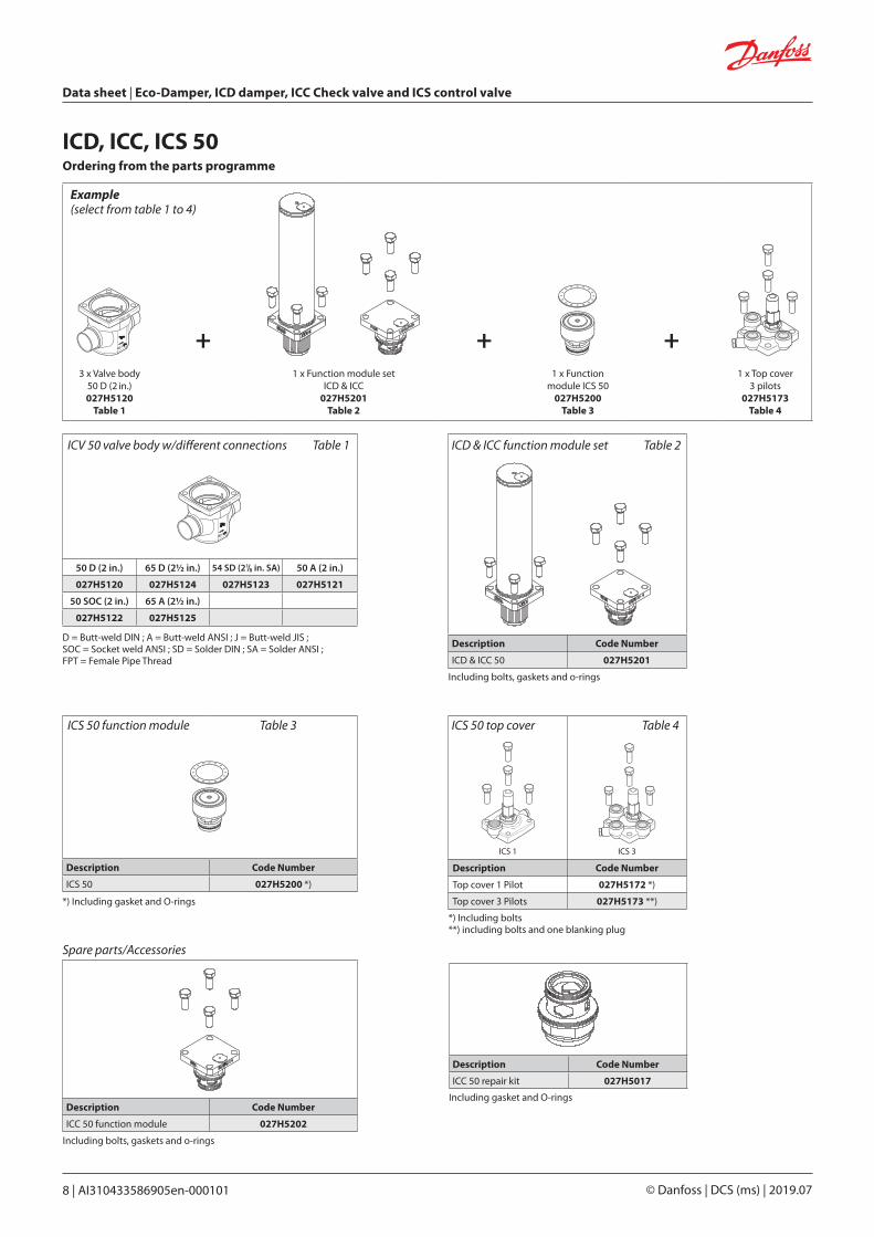
ICD, ICC, ICS 50
50 D (2 in.) 65 D (21/2 in.) 54 SD (21/8 in. SA) 50 A (2 in.)
027H5120 027H5124 027H5123 027H5121
50 SOC (2 in.) 65 A (21/2 in.)
027H5122 027H5125
+ + +3 x Valve body
50 D (2 in.)027H5120
Table 1
1 x Function module set ICD & ICC
027H5201Table 2
1 x Function module ICS 50
027H5200Table 3
1 x Top cover 3 pilots
027H5173Table 4
Example (select from table 1 to 4)
D = Butt-weld DIN ; A = Butt-weld ANSI ; J = Butt-weld JIS ; SOC = Socket weld ANSI ; SD = Solder DIN ; SA = Solder ANSI ; FPT = Female Pipe Thread
ICS 50 function module Table 3 ICS 50 top cover Table 4
ICV 50 valve body w/different connections Table 1
Description Code Number
ICD & ICC 50 027H5201
Including bolts, gaskets and o-rings
ICD & ICC function module set Table 2
Description Code Number
ICC 50 repair kit 027H5017
Including gasket and O-rings
Spare parts/Accessories
Description Code Number
ICC 50 function module 027H5202
Including bolts, gaskets and o-rings
Data sheet | Eco-Damper, ICD damper, ICC Check valve and ICS control valve
© Danfoss | DCS (ms) | 2019.07 AI310433586905en-000101 | 9
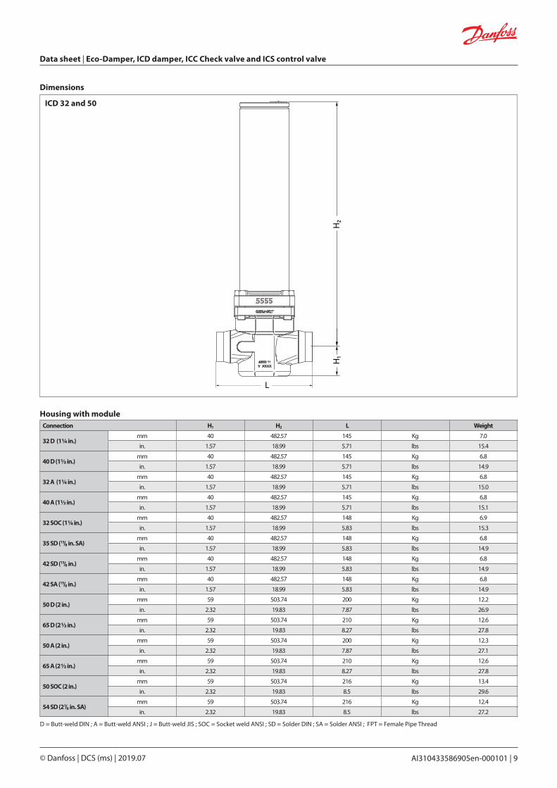
Dimensions
D = Butt-weld DIN ; A = Butt-weld ANSI ; J = Butt-weld JIS ; SOC = Socket weld ANSI ; SD = Solder DIN ; SA = Solder ANSI ; FPT = Female Pipe Thread
ICD 32 and 50
H1
H2
L
Connection H1 H2 L Weight
32 D (11/4 in.)mm 40 482.57 145 Kg 7.0
in. 1.57 18.99 5.71 lbs 15.4
40 D (11/2 in.)mm 40 482.57 145 Kg 6.8
in. 1.57 18.99 5.71 lbs 14.9
32 A (11/4 in.)mm 40 482.57 145 Kg 6.8
in. 1.57 18.99 5.71 lbs 15.0
40 A (11/2 in.)mm 40 482.57 145 Kg 6.8
in. 1.57 18.99 5.71 lbs 15.1
32 SOC (11/4 in.)mm 40 482.57 148 Kg 6.9
in. 1.57 18.99 5.83 lbs 15.3
35 SD (13/8 in. SA)mm 40 482.57 148 Kg 6.8
in. 1.57 18.99 5.83 lbs 14.9
42 SD (15/8 in.)mm 40 482.57 148 Kg 6.8
in. 1.57 18.99 5.83 lbs 14.9
42 SA (15/8 in.)mm 40 482.57 148 Kg 6.8
in. 1.57 18.99 5.83 lbs 14.9
50 D (2 in.)mm 59 503.74 200 Kg 12.2
in. 2.32 19.83 7.87 lbs 26.9
65 D (21/2 in.)mm 59 503.74 210 Kg 12.6
in. 2.32 19.83 8.27 lbs 27.8
50 A (2 in.)mm 59 503.74 200 Kg 12.3
in. 2.32 19.83 7.87 lbs 27.1
65 A (21/2 in.)mm 59 503.74 210 Kg 12.6
in. 2.32 19.83 8.27 lbs 27.8
50 SOC (2 in.)mm 59 503.74 216 Kg 13.4
in. 2.32 19.83 8.5 lbs 29.6
54 SD (21/8 in. SA)mm 59 503.74 216 Kg 12.4
in. 2.32 19.83 8.5 lbs 27.2
Housing with module
Data sheet | Eco-Damper, ICD damper, ICC Check valve and ICS control valve
© Danfoss | DCS (ms) | 2019.0710 | AI310433586905en-000101
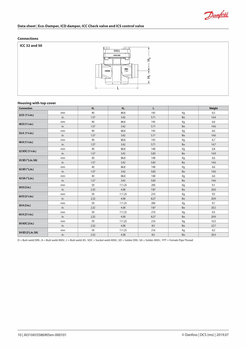
Connections
ICC 32 and 50
D = Butt-weld DIN ; A = Butt-weld ANSI ; J = Butt-weld JIS ; SOC = Socket weld ANSI ; SD = Solder DIN ; SA = Solder ANSI ; FPT = Female Pipe Thread
H1
H2
L
Housing with top coverConnection H1 H2 L Weight
32 D (11/4 in.)mm 40 86.8 145 Kg 6.5
in. 1.57 3.42 5.71 lbs 14.4
40 D (11/2 in.)mm 40 86.8 145 Kg 6.6
in. 1.57 3.42 5.71 lbs 14.6
32 A (11/4 in.)mm 40 86.8 145 Kg 6.6
in. 1.57 3.42 5.71 lbs 14.6
40 A (11/2 in.)mm 40 86.8 145 Kg 6.7
in. 1.57 3.42 5.71 lbs 14.7
32 SOC (11/4 in.)mm 40 86.8 148 Kg 6.8
in. 1.57 3.42 5.83 lbs 14.9
35 SD (13/8 in. SA)mm 40 86.8 148 Kg 6.6
in. 1.57 3.42 5.83 lbs 14.6
42 SD (15/8 in.)mm 40 86.8 148 Kg 6.6
in. 1.57 3.42 5.83 lbs 14.6
42 SA (15/8 in.)mm 40 86.8 148 Kg 6.6
in. 1.57 3.42 5.83 lbs 14.6
50 D (2 in.)mm 59 111.25 200 Kg 9.1
in. 2.32 4.38 7.87 lbs 20.0
65 D (21/2 in.)mm 59 111.25 210 Kg 9.5
in. 2.32 4.38 8.27 lbs 20.9
50 A (2 in.)mm 59 111.25 200 Kg 9.1
in. 2.32 4.38 7.87 lbs 20.2
65 A (21/2 in.)mm 59 111.25 210 Kg 9.5
in. 2.32 4.38 8.27 lbs 20.9
50 SOC (2 in.)mm 59 111.25 216 Kg 10.3
in. 2.32 4.38 8.5 lbs 22.7
54 SD (21/8 in. SA)mm 59 111.25 216 Kg 9.2
in. 2.32 4.38 8.5 lbs 20.3
Data sheet | Eco-Damper, ICD damper, ICC Check valve and ICS control valve
© Danfoss | DCS (ms) | 2019.07 AI310433586905en-000101 | 11
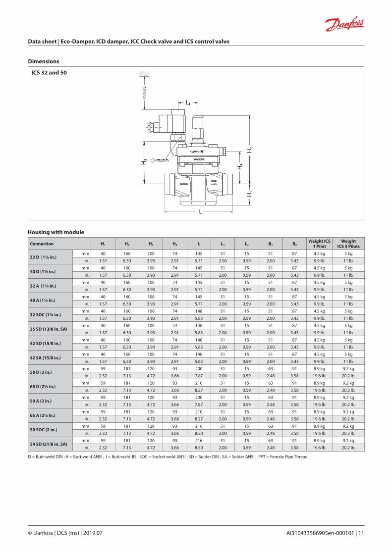
Dimensions
ICS 32 and 50
Connection H1 H2 H3 H4 L L1 L2 B1 B2Weight ICS
1 PilotWeight
ICS 3 Pilots
32 D (11/4 in.)mm 40 160 100 74 145 51 15 51 87 4.5 kg 5 kg
in. 1.57 6.30 3.93 2.91 5.71 2.00 0.59 2.00 3.43 9.9 lb. 11 lb.
40 D (11/2 in.)mm 40 160 100 74 145 51 15 51 87 4.5 kg 5 kg
in. 1.57 6.30 3.93 2.91 5.71 2.00 0.59 2.00 3.43 9.9 lb. 11 lb.
32 A (11/4 in.)mm 40 160 100 74 145 51 15 51 87 4.5 kg 5 kg
in. 1.57 6.30 3.93 2.91 5.71 2.00 0.59 2.00 3.43 9.9 lb. 11 lb.
40 A (11/2 in.)mm 40 160 100 74 145 51 15 51 87 4.5 kg 5 kg
in. 1.57 6.30 3.93 2.91 5.71 2.00 0.59 2.00 3.43 9.9 lb. 11 lb.
32 SOC (11/4 in.)mm 40 160 100 74 148 51 15 51 87 4.5 kg 5 kg
in. 1.57 6.30 3.93 2.91 5.83 2.00 0.59 2.00 3.43 9.9 lb. 11 lb.
35 SD (13/8 in. SA)mm 40 160 100 74 148 51 15 51 87 4.5 kg 5 kg
in. 1.57 6.30 3.93 2.91 5.83 2.00 0.59 2.00 3.43 9.9 lb. 11 lb.
42 SD (15/8 in.)mm 40 160 100 74 148 51 15 51 87 4.5 kg 5 kg
in. 1.57 6.30 3.93 2.91 5.83 2.00 0.59 2.00 3.43 9.9 lb. 11 lb.
42 SA (15/8 in.)mm 40 160 100 74 148 51 15 51 87 4.5 kg 5 kg
in. 1.57 6.30 3.93 2.91 5.83 2.00 0.59 2.00 3.43 9.9 lb. 11 lb.
50 D (2 in.)mm 59 181 120 93 200 51 15 63 91 8.9 kg 9.2 kg
in. 2.32 7.13 4.72 3.66 7.87 2.00 0.59 2.48 3.58 19.6 lb. 20.2 lb.
65 D (21/2 in.)mm 59 181 120 93 210 51 15 63 91 8.9 kg 9.2 kg
in. 2.32 7.13 4.72 3.66 8.27 2.00 0.59 2.48 3.58 19.6 lb. 20.2 lb.
50 A (2 in.)mm 59 181 120 93 200 51 15 63 91 8.9 kg 9.2 kg
in. 2.32 7.13 4.72 3.66 7.87 2.00 0.59 2.48 3.58 19.6 lb. 20.2 lb.
65 A (21/2 in.)mm 59 181 120 93 210 51 15 63 91 8.9 kg 9.2 kg
in. 2.32 7.13 4.72 3.66 8.27 2.00 0.59 2.48 3.58 19.6 lb. 20.2 lb.
50 SOC (2 in.)mm 59 181 120 93 216 51 15 63 91 8.9 kg 9.2 kg
in. 2.32 7.13 4.72 3.66 8.50 2.00 0.59 2.48 3.58 19.6 lb. 20.2 lb.
54 SD (21/8 in. SA)mm 59 181 120 93 216 51 15 63 91 8.9 kg 9.2 kg
in. 2.32 7.13 4.72 3.66 8.50 2.00 0.59 2.48 3.58 19.6 lb. 20.2 lb.
H1
H2
H4
L1
H3
L
D = Butt-weld DIN ; A = Butt-weld ANSI ; J = Butt-weld JIS ; SOC = Socket weld ANSI ; SD = Solder DIN ; SA = Solder ANSI ; FPT = Female Pipe Thread
Housing with module

© Danfoss | DCS (ms) | 2019.07 AI310433586905en-000101 | 12


![ACATacat.or.th/download/acat_or_th/journal-4/04 - 04.pdf · APmin APmax Appendix G [1] AP APmax Overpressure Relief Damper Damper 12 Relief Damper Relief Damper (Vent) Fire Damper](https://img.dokumen.tips/doc/110x75/5f7cb481641db55595223717/-04pdf-apmin-apmax-appendix-g-1-ap-apmax-overpressure-relief-damper-damper.jpg)


