Embed Size (px)
Citation preview
EBARA VARIABLE SPEED and CONSTANT PRESSURE BOOSTER SYSTEM
UN
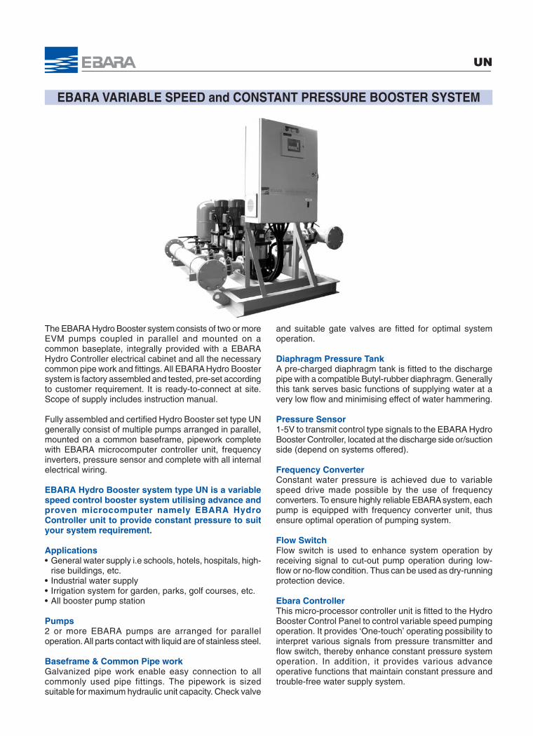
The EBARA Hydro Booster system consists of two or moreEVM pumps coupled in parallel and mounted on acommon baseplate, integrally provided with a EBARAHydro Controller electrical cabinet and all the necessarycommon pipe work and fittings. All EBARA Hydro Boostersystem is factory assembled and tested, pre-set accordingto customer requirement. It is ready-to-connect at site.Scope of supply includes instruction manual.
Fully assembled and certified Hydro Booster set type UNgenerally consist of multiple pumps arranged in parallel,mounted on a common baseframe, pipework completewith EBARA microcomputer controller unit, frequencyinverters, pressure sensor and complete with all internalelectrical wiring.
EBARA Hydro Booster system type UN is a variablespeed control booster system utilising advance andproven microcomputer namely EBARA HydroController unit to provide constant pressure to suityour system requirement.
Applications• General water supply i.e schools, hotels, hospitals, high-
rise buildings, etc.• Industrial water supply• Irrigation system for garden, parks, golf courses, etc.• All booster pump station
Pumps2 or more EBARA pumps are arranged for paralleloperation. All parts contact with liquid are of stainless steel.
Baseframe & Common Pipe workGalvanized pipe work enable easy connection to allcommonly used pipe fittings. The pipework is sizedsuitable for maximum hydraulic unit capacity. Check valve
and suitable gate valves are fitted for optimal systemoperation.
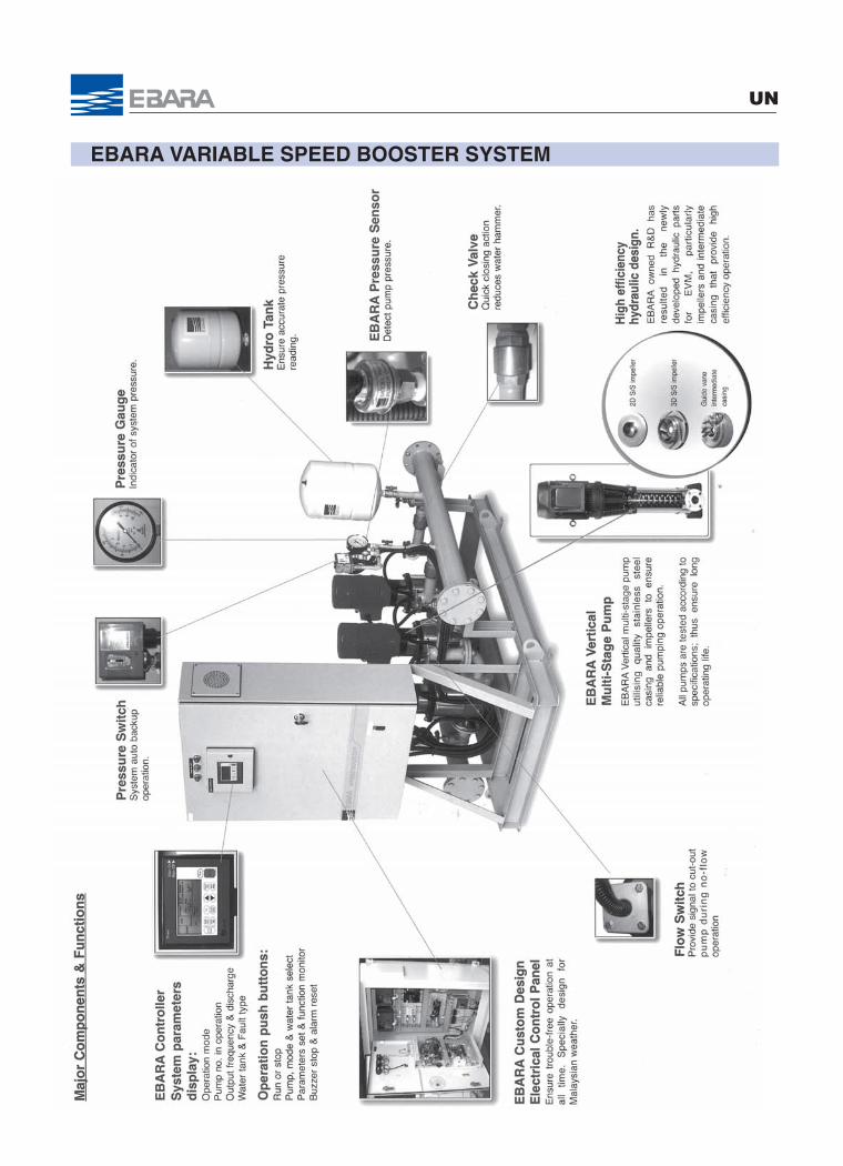
Diaphragm Pressure TankA pre-charged diaphragm tank is fitted to the dischargepipe with a compatible Butyl-rubber diaphragm. Generallythis tank serves basic functions of supplying water at avery low flow and minimising effect of water hammering.
Pressure Sensor1-5V to transmit control type signals to the EBARA HydroBooster Controller, located at the discharge side or/suctionside (depend on systems offered).
Frequency ConverterConstant water pressure is achieved due to variablespeed drive made possible by the use of frequencyconverters. To ensure highly reliable EBARA system, eachpump is equipped with frequency converter unit, thusensure optimal operation of pumping system.
Flow SwitchFlow switch is used to enhance system operation byreceiving signal to cut-out pump operation during low-flow or no-flow condition. Thus can be used as dry-runningprotection device.
Ebara ControllerThis micro-processor controller unit is fitted to the HydroBooster Control Panel to control variable speed pumpingoperation. It provides ‘One-touch’ operating possibility tointerpret various signals from pressure transmitter andflow switch, thereby enhance constant pressure systemoperation. In addition, it provides various advanceoperative functions that maintain constant pressure andtrouble-free water supply system.

ISOMETRIC DRAWING
UN
2 Controller
10
Discharge Manifold
Check Valve 11
Gate Valve
Pressure Transmitter
Expansion Tank
Suction Manifold
Pressure Gauge
Pressure Switch
6
8
9
7
Pump
4
5
3
Part Name
Control Panel 1
No.
12 Flow Switch
11
9 10
8
7
2
1
3
4 5
6
12
EBARA VARIABLE SPEED BOOSTER SYSTEM
UN
EBARA VARIABLE SPEED BOOSTER SYSTEM
UN
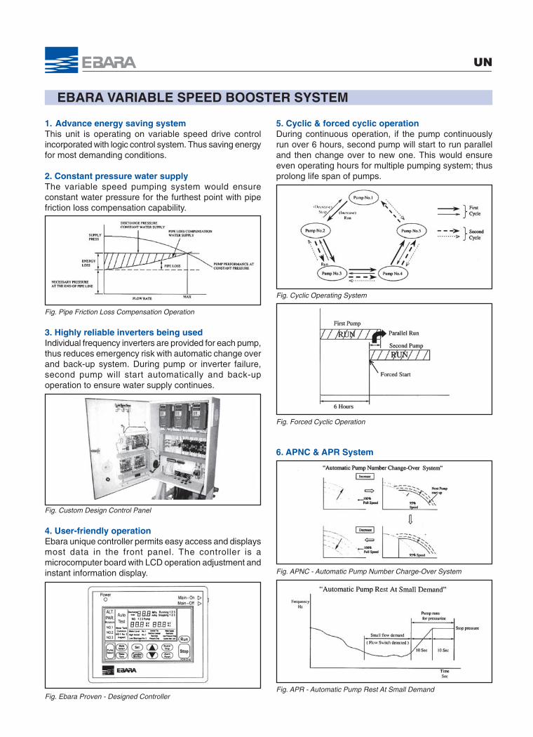
1. Advance energy saving systemThis unit is operating on variable speed drive controlincorporated with logic control system. Thus saving energyfor most demanding conditions.
2. Constant pressure water supplyThe variable speed pumping system would ensureconstant water pressure for the furthest point with pipefriction loss compensation capability.
Fig. Pipe Friction Loss Compensation Operation
3. Highly reliable inverters being usedIndividual frequency inverters are provided for each pump,thus reduces emergency risk with automatic change overand back-up system. During pump or inverter failure,second pump will start automatically and back-upoperation to ensure water supply continues.
Fig. Custom Design Control Panel
4. User-friendly operationEbara unique controller permits easy access and displaysmost data in the front panel. The controller is amicrocomputer board with LCD operation adjustment andinstant information display.
Fig. Ebara Proven - Designed Controller
5. Cyclic & forced cyclic operationDuring continuous operation, if the pump continuouslyrun over 6 hours, second pump will start to run paralleland then change over to new one. This would ensureeven operating hours for multiple pumping system; thusprolong life span of pumps.
Fig. Cyclic Operating System
Fig. Forced Cyclic Operation
6. APNC & APR System
Fig. APNC - Automatic Pump Number Charge-Over System
Fig. APR - Automatic Pump Rest At Small Demand
EBARA VARIABLE SPEED BOOSTER SYSTEM - OPERATION METHOD
UN
➉➄➀ ➅
➈➇➆➃➂➁
Ad
vanc
e p
ump
sta
rt
Ad
vanc
e p
ump
sta
rt
Ad
vanc
e p
ump
sto
p
Ad
vanc
e p
ump
sto
p
2nd
pum
p s
tart
3rd
to
5th
pum
p s
tart
5th
to 2
nd p
ump
sto
p
2nd
pum
p s
tart
3rd
to
5th
pum
p s
tart
5th
to 2
nd p
ump
sto
p
When water flow is low
When water flow is great
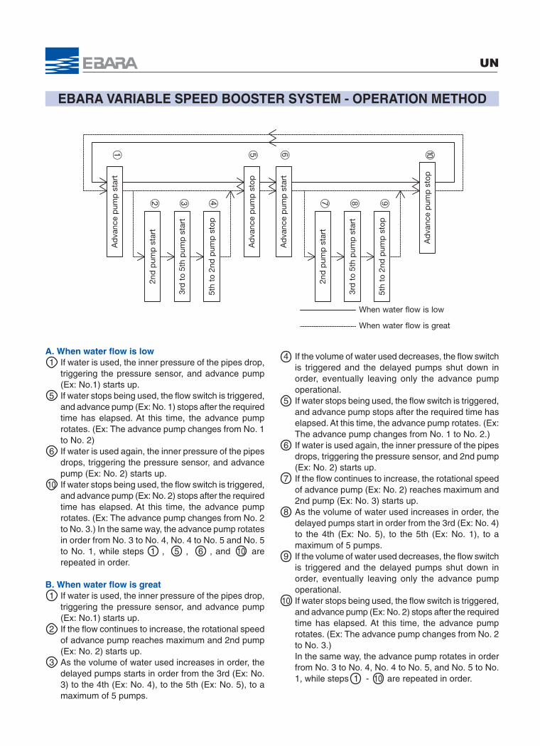
A. When water flow is low1 If water is used, the inner pressure of the pipes drop,
triggering the pressure sensor, and advance pump(Ex: No.1) starts up.
5 If water stops being used, the flow switch is triggered,and advance pump (Ex: No. 1) stops after the requiredtime has elapsed. At this time, the advance pumprotates. (Ex: The advance pump changes from No. 1to No. 2)
6 If water is used again, the inner pressure of the pipesdrops, triggering the pressure sensor, and advancepump (Ex: No. 2) starts up.
10 If water stops being used, the flow switch is triggered,and advance pump (Ex: No. 2) stops after the requiredtime has elapsed. At this time, the advance pumprotates. (Ex: The advance pump changes from No. 2to No. 3.) In the same way, the advance pump rotatesin order from No. 3 to No. 4, No. 4 to No. 5 and No. 5to No. 1, while steps 1 , 5 , 6 , and 10 arerepeated in order.
B. When water flow is great1 If water is used, the inner pressure of the pipes drop,
triggering the pressure sensor, and advance pump(Ex: No.1) starts up.
2 If the flow continues to increase, the rotational speedof advance pump reaches maximum and 2nd pump(Ex: No. 2) starts up.
3 As the volume of water used increases in order, thedelayed pumps starts in order from the 3rd (Ex: No.3) to the 4th (Ex: No. 4), to the 5th (Ex: No. 5), to amaximum of 5 pumps.
4 If the volume of water used decreases, the flow switchis triggered and the delayed pumps shut down inorder, eventually leaving only the advance pumpoperational.
5 If water stops being used, the flow switch is triggered,and advance pump stops after the required time haselapsed. At this time, the advance pump rotates. (Ex:The advance pump changes from No. 1 to No. 2.)
6 If water is used again, the inner pressure of the pipesdrops, triggering the pressure sensor, and 2nd pump(Ex: No. 2) starts up.
7 If the flow continues to increase, the rotational speedof advance pump (Ex: No. 2) reaches maximum and2nd pump (Ex: No. 3) starts up.
8 As the volume of water used increases in order, thedelayed pumps start in order from the 3rd (Ex: No. 4)to the 4th (Ex: No. 5), to the 5th (Ex: No. 1), to amaximum of 5 pumps.
9 If the volume of water used decreases, the flow switchis triggered and the delayed pumps shut down inorder, eventually leaving only the advance pumpoperational.
10 If water stops being used, the flow switch is triggered,and advance pump (Ex: No. 2) stops after the requiredtime has elapsed. At this time, the advance pumprotates. (Ex: The advance pump changes from No. 2to No. 3.)In the same way, the advance pump rotates in orderfrom No. 3 to No. 4, No. 4 to No. 5, and No. 5 to No.1, while steps 1 - 10 are repeated in order.
EBARA VARIABLE SPEED BOOSTER SYSTEM - CONTROLLER
UN
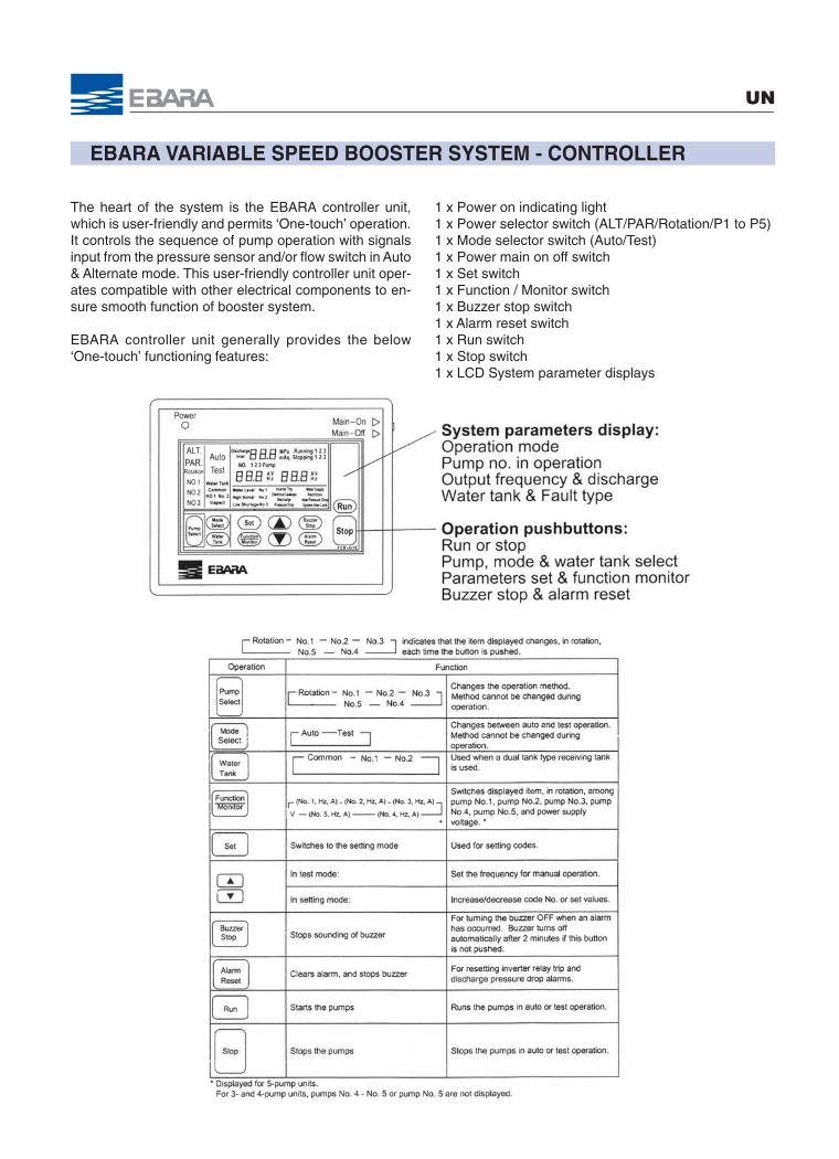
The heart of the system is the EBARA controller unit,which is user-friendly and permits ‘One-touch’ operation.It controls the sequence of pump operation with signalsinput from the pressure sensor and/or flow switch in Auto& Alternate mode. This user-friendly controller unit oper-ates compatible with other electrical components to en-sure smooth function of booster system.
EBARA controller unit generally provides the below‘One-touch’ functioning features:
1 x Power on indicating light1 x Power selector switch (ALT/PAR/Rotation/P1 to P5)1 x Mode selector switch (Auto/Test)1 x Power main on off switch1 x Set switch1 x Function / Monitor switch1 x Buzzer stop switch1 x Alarm reset switch1 x Run switch1 x Stop switch1 x LCD System parameter displays
EBARA VARIABLE SPEED BOOSTER SYSTEM - UNIQUE FEATURE
UN
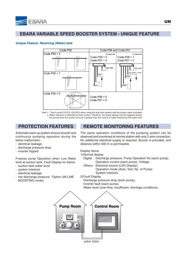
Unique Feature- Receiving (Water) tank
Note 1. * Short circuit E12-E15, E22-E25 (when using the dual tank system) with the jumper cable (included).2. Water reduction is detected by timer control. Therefore, the empty display may be triggered during
the period when the suction amount is greater than the volume of water flowing into the water tank.
PROTECTION FEATURESAutomatic back up system ensure smooth andcontinuous pumping operation during thebelow malfunction:- electrical leakage,- discharge pressure drop,- inverter tripped
Freezes pump Operation when Low Waterlevel at suction tank. Fault Display for below:- suction tank water level- system interlock- electrical leakage- low discharge pressure. *Option (IN-LINE
BOOSTING mode)
The same operation conditions of the pumping system can beobserved and monitored at remote station with only 2 wire connection.No additional electrical supply is required. Buzzer is provided, anddistance within 500 m is permissible.
Display Items:1)Normal display
Digital : Discharge pressure, Pump Operation Hz (each pump).Operation current (each pump), Voltage.
Others : Electrical source (LED Display).Operation mode (Auto, Test, No. of Pump)System interlock.
2)Fault DisplayDischarge pressure drop (each pump),Inverter fault (each pump),Water level (over-flow, insufficient, shortage conditions).
REMOTE MONITORING FEATURES
SPECIFICATIONS FOR VARIABLE SPEED PRESSURE BOOSTER UNIT
UNO
pti
on
al
Sta
nd
ard
Item
Inve
rter
var
iab
le s
pee
d c
ontr
ol d
rive
Pum
p s
pee
dO
per
atio
n sy
stem
Con
stan
t p
ress
ure
with
sys
tem
loss
com
pen
satio
nP
ress
ure
cont
rol
Sin
gle
alte
rnat
e, P
aral
lel a
ltern
ate,
Up
to
5 p
ump
s cy
clic
Num
ber
of p
ump
con
trol
Pum
ps
rest
at
smal
l flo
w r
ate
Out
doo
rIn
doo
rIn
stal
latio
n ar
ea
Am
bie
nt t
emp
erat
ure
Up
to
40ºC
Wea
ther
-pro
of a
vaila
ble
Ver
tical
mul
tista
ge P
ump
: Mod
el E
VM
Pum
p3M
, CD
X an
d ot
her E
BA
RA
mod
elTh
ree
pha
se, 3
80/4
00/4
15 V
, 50
Hz
Pow
er s
ourc
eP
re-c
harg
ed D
iap
hrag
mTy
pe
Pre
ssur
e ta
nkO
ver
18L
18L
Cap
acity
Up
to
20 b
ar10
bar
Max
. wor
king
pre
ssur
e3
Wire
for
DC
12V
Pre
ssur
e se
nsor
Out
put
Vol
tage
1 -
5V
Wat
er le
vel b
oard
,In
vert
er (e
ach
pum
p),
Con
trol
pan
el (R
emot
e ty
pe)
Mai
n co
mp
onen
tsC
ontr
ol p
anel
& C
ontr
olle
rM
ain
sup
ply
noi
se fi
lter
Sur
ge p
rote
ctor
Mai
n ci
rcui
t b
reak
er, M
ain
cont
rol C
PU
boa
rdIn
terf
ace
boa
rd, P
ilot
light
, Iso
lato
r, V
olta
ge d
etec
tion
boa
rdC
ontr
ol c
ircui
t no
ise
filte
r, E
lect
ric le
akag
e b
reak
erE
lect
ric t
herm
al d
evic
e, c
ontr
olle
d b
y m
icro
com
put
erP
rote
ctio
nD
isch
arge
pre
ssur
e {d
igita
l dis
pla
y}P
ump
op
erat
ion
curr
ent
{dig
ital d
isp
lay}
Vol
tage
{d
igita
l dis
pla
y}P
ump
op
erat
ion
freq
uenc
y {d
igita
l dis
pla
y}P
ower
{re
d L
ED
}O
per
atio
n co
nditi
on {
runn
ing
pum
p}
Op
erat
ion
mod
e {A
utom
atic
or
man
ual}
Sto
rage
tan
k se
lect
ion
{Tan
k 1
or 2
}S
tora
ge t
ank
wat
er le
vel c
ond
ition
{no
rmal
}S
yste
m in
terlo
ckFa
ilure
: S
hort
age
or fu
ll of
sto
rage
tan
k
Low
dis
char
ge p
ress
ure.
*O
ptio
n: IN
-LIN
E B
OO
STI
NG
mod
e
Inve
rter
trip
Dis
pla
y Ite
ms
Pum
p r
unni
ngP
ump
failu
reS
tora
ge t
ank
cond
ition
{Fu
ll, lo
w, s
hort
age}
Ext
erna
l out
put
sig
nal
(No
volta
ge, n
orm
al o
pen
cont
act)
Sys
tem
inte
rlock
{on
/off
}E
xter
nal i
nput
sig
nal
(No
volta
ge, n
orm
al o
pen
cont
act)

CUSTOM BUILT HYDRO BOOSTER SYSTEM (available upon request)
UN
Inline boosting system
specially design for:
• automatic water supply
system.
• water supply distribution.
• automatic booster system
for housing estate,
hospitals, condominium
and high-rise building.
• golf course irrigation.
Applications
• general boosting for
factories, plant and
booster station.
• consistent pressure.
• no suction tank required i.e:
direct boosting from suction
pipe.
• flexible usage i.e. capable of
integrating with existing.
pumping system with minimal
modification works.
• consistent pressure.
• reduce storage tank size.
• empties water effectively to
process and utilities etc.
• automatic irrigation of
required capacity and
pressure setting.
• economical design.
• economy set.
Features / Benefits
• automatic boosting system
for large-scale water supply.
• ensure constant pressure.
• maintenance free operation.
Product Options
UN-IB
UN-GB
UN-GC
UN-SP
0
200
Tota
l H
ead
(m)
9
120
100
140
160
180
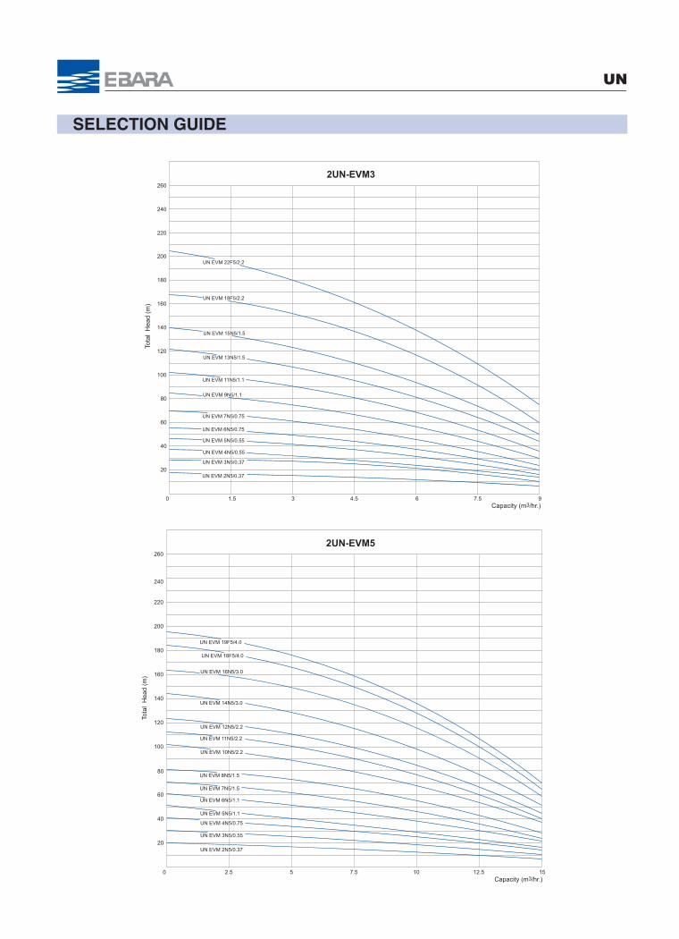
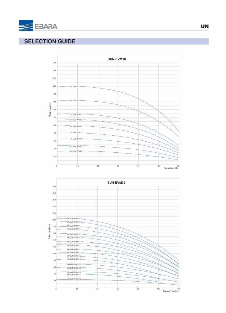
2UN-EVM3
220
4.5
20
40
60
80
UN EVM 18F5/2.2
1.5 3 6 7.5
240
260
Capacity (m3/hr.)
UN EVM 13N5/1.5
UN EVM 22F5/2.2
UN EVM 15N5/1.5
UN EVM 9N5/1.1
UN EVM 11N5/1.1
UN EVM 6N5/0.75
UN EVM 7N5/0.75
UN EVM 3N5/0.37
UN EVM 4N5/0.55
UN EVM 5N5/0.55
UN EVM 2N5/0.37
60
40
20
7.5
260
2UN-EVM5
180
160
140
100
120
15
Tota
l H
ead
(m)
200
0
UN EVM 5N5/1.1
80
10 12.552.5
240
220
Capacity (m3/hr.)
UN EVM 19F5/4.0
UN EVM 16N5/3.0
UN EVM 12N5/2.2
UN EVM 14N5/3.0
UN EVM 10N5/2.2
UN EVM 6N5/1.1
UN EVM 7N5/1.5
UN EVM 8N5/1.5
UN EVM 3N5/0.55
UN EVM 4N5/0.75
UN EVM 2N5/0.37
UN EVM 11N5/2.2
UN EVM 18F5/4.0
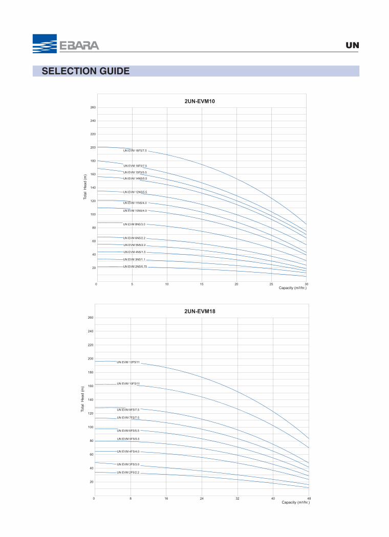
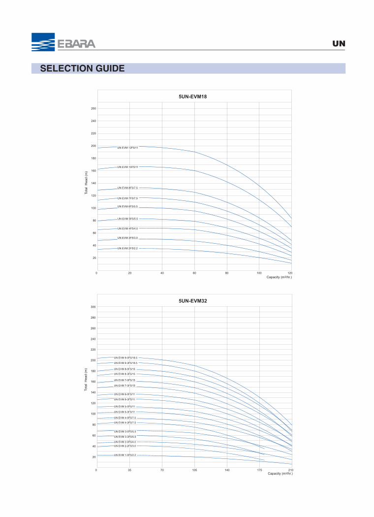
SELECTION GUIDE
UN
SELECTION GUIDE
UN
80
60
40
20
15
260
2UN-EVM10
180
160
140
100
120
30
Tota
l H
ead
(m)
200
0 20 25105
240
220
Capacity (m3/hr.)
UN EVM 16F5/7.5
UN EVM 15F5/5.5
UN EVM 14N5/5.5
UN EVM 10N5/4.0
UN EVM 11N5/4.0
UN EVM 12N5/5.5
UN EVM 8N5/3.0
UN EVM 5N5/2.2
UN EVM 6N5/2.2
UN EVM 3N5/1.1
UN EVM 2N5/0.75
UN EVM 4N5/1.5
UN EVM 18F5/7.5
0
200
Tota
l H
ead
(m)
48
120
100
140
160
180
2UN-EVM18260
24
20
40
60
80
32 408 16
240
220
Capacity (m3/hr.)
UN EVM 8F5/7.5
UN EVM 10F5/11
UN EVM 7F5/7.5
UN EVM 12F5/11
UN EVM 2F5/2.2
UN EVM 5F5/5.5
UN EVM 6F5/5.5
UN EVM 3F5/3.0
UN EVM 4F5/4.0
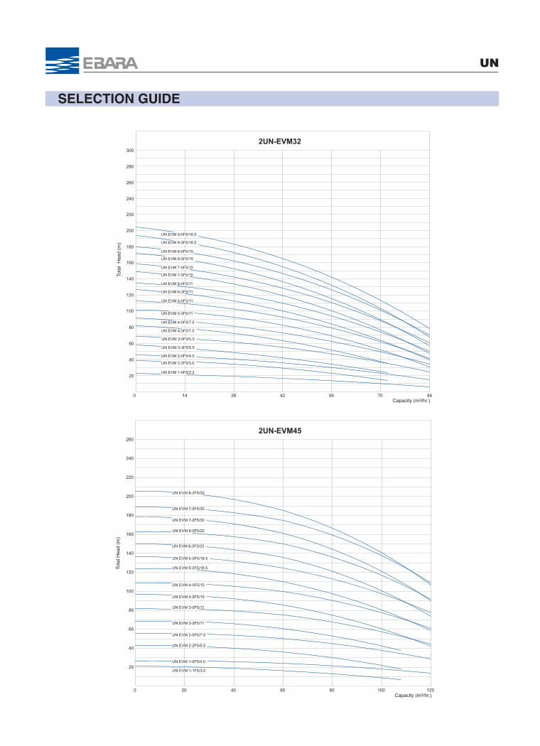
SELECTION GUIDE
UN
80
60
40
20
42
300
240
220
2UN-EVM32
180
160
140
100
120
84
Tota
l H
ead
(m)
200
0 2814 56 70
280
260
Capacity (m3/hr.)
UN EVM 1-0F5/2.2
UN EVM 2-2F5/3.0
UN EVM 2-0F5/4.0
UN EVM 3-3F5/5.5
UN EVM 3-0F5/5.5
UN EVM 4-3F5/7.5
UN EVM 4-0F5/7.5
UN EVM 5-3F5/11
UN EVM 5-0F5/11
UN EVM 6-3F5/11
UN EVM 6-0F5/11
UN EVM 7-3F5/15
UN EVM 7-0F5/15
UN EVM 8-3F5/15
UN EVM 8-0F5/15
UN EVM 9-3F5/18.5
UN EVM 9-0F5/18.5
120
180
160
260
200
80
60
100
120
140
0
20
40
Tota
l Hea
d (m
)
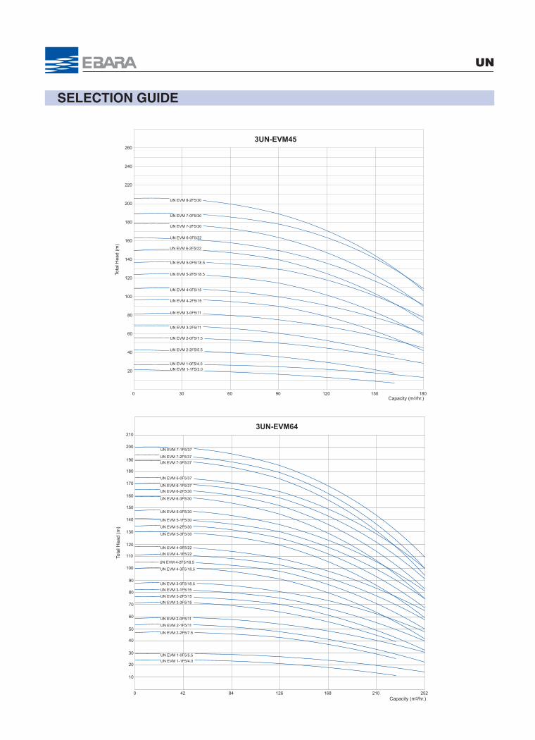
2UN-EVM45
604020 80 100
240
220
Capacity (m3/hr.)
UN EVM 2-0F5/7.5
UN EVM 3-2F5/11
UN EVM 3-0F5/11
UN EVM 7-2F5/30
UN EVM 6-2F5/22
UN EVM 6-0F5/22
UN EVM 5-0F5/18.5
UN EVM 4-0F5/15
UN EVM 5-2F5/18.5
UN EVM 4-2F5/15
UN EVM 1-1F5/3.0
UN EVM 1-0F5/4.0
UN EVM 2-2F5/5.5
UN EVM 8-2F5/30
UN EVM 7-0F5/30
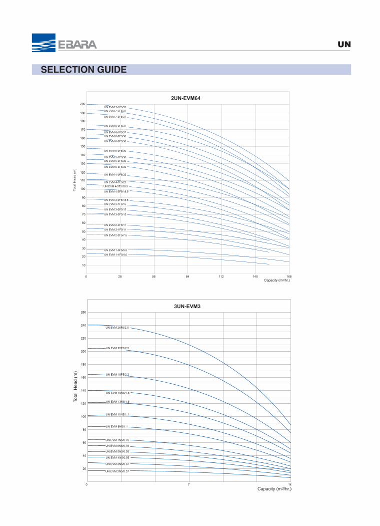
SELECTION GUIDE
UN
84
2UN-EVM64
Tota
l Hea
d (m
)
40
20
0
140
120
100
60
80
200
160
180
168
10
30
50
70
90
110
130
150
170
190
112 1405628Capacity (m3/hr.)
UN EVM 6-2F5/30
UN EVM 6-1F5/37
UN EVM 6-0F5/37
UN EVM 5-0F5/30
UN EVM 6-3F5/30
UN EVM 5-1F5/30
UN EVM 4-0F5/22
UN EVM 5-3F5/30
UN EVM 5-2F5/30
UN EVM 4-3F5/18.5
UN EVM 4-2F5/18.5
UN EVM 4-1F5/22
UN EVM 3-1F5/15
UN EVM 3-0F5/18.5
UN EVM 3-2F5/15
UN EVM 2-0F5/11
UN EVM 3-3F5/15
UN EVM 2-1F5/11
UN EVM 1-1F5/4.0
UN EVM 1-0F5/5.5
UN EVM 2-2F5/7.5
UN EVM 7-1F5/37UN EVM 7-2F5/37
UN EVM 7-3F5/37
80
60
40
20
260
240
220
180
160
140
100
120
Tota
l H
ead
(m)
200
3UN-EVM3
UN EVM 18F5/2.2
0 147
Capacity (m3/hr.)
UN EVM 13N5/1.5
UN EVM 26F5/3.0
UN EVM 22F5/2.2
UN EVM 15N5/1.5
UN EVM 9N5/1.1
UN EVM 11N5/1.1
UN EVM 6N5/0.75
UN EVM 7N5/0.75
UN EVM 3N5/0.37
UN EVM 4N5/0.55
UN EVM 5N5/0.55
UN EVM 2N5/0.37
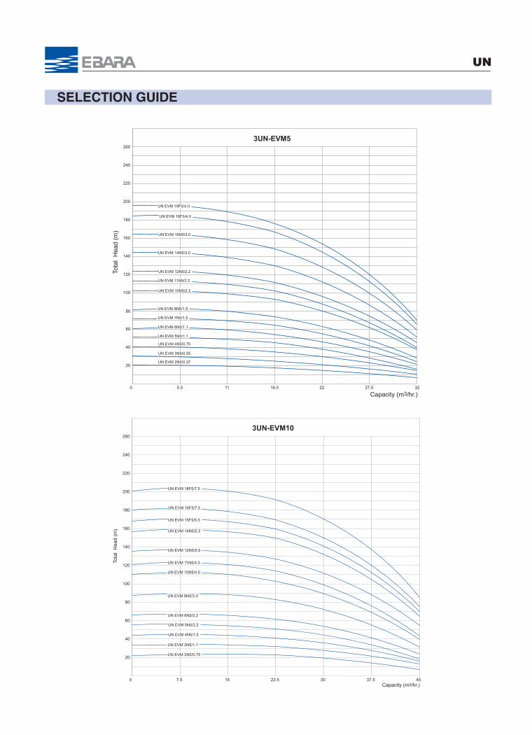
SELECTION GUIDE
UN
80
0
200
Tota
l H
ead
(m)
120
100
140
160
180
220
240
260
20
40
60
3UN-EVM5
3216.5
UN EVM 5N5/1.1
115.5 22 27.5
Capacity (m3/hr.)
UN EVM 11N5/2.2
UN EVM 2N5/0.37
UN EVM 4N5/0.75
UN EVM 3N5/0.55
UN EVM 8N5/1.5
UN EVM 7N5/1.5
UN EVM 6N5/1.1
UN EVM 10N5/2.2
UN EVM 14N5/3.0
UN EVM 12N5/2.2
UN EVM 16N5/3.0
UN EVM 19F5/4.0
UN EVM 18F5/4.0
0
200
Tota
l H
ead
(m)
120
100
140
160
180
220
240
260
20
40
60
80
3UN-EVM10
4522.5 30 37.5157.5Capacity (m3/hr.)
UN EVM 4N5/1.5
UN EVM 2N5/0.75
UN EVM 3N5/1.1
UN EVM 6N5/2.2
UN EVM 5N5/2.2
UN EVM 8N5/3.0
UN EVM 12N5/5.5
UN EVM 11N5/4.0
UN EVM 10N5/4.0
UN EVM 14N5/5.5
UN EVM 15F5/5.5
UN EVM 16F5/7.5
UN EVM 18F5/7.5
SELECTION GUIDE
UN
80
60
40
20
260
240
220
180
160
140
100
120
Tota
l H
ead
(m)
200
0
3UN-EVM18
48 963216 64 80Capacity (m3/hr.)
UN EVM 4F5/4.0
UN EVM 3F5/3.0
UN EVM 6F5/5.5
UN EVM 5F5/5.5
UN EVM 2F5/2.2
UN EVM 12F5/11
UN EVM 7F5/7.5
UN EVM 10F5/11
UN EVM 8F5/7.5
80
60
40
20
63
260
240
220
3UN-EVM32
180
160
140
100
120
126
Tota
l H
ead
(m)
200
0
280
300
84 1054221Capacity (m3/hr.)
UN EVM 1-0F5/2.2
UN EVM 2-2F5/3.0
UN EVM 2-0F5/4.0
UN EVM 3-3F5/5.5
UN EVM 3-0F5/5.5
UN EVM 4-3F5/7.5
UN EVM 4-0F5/7.5
UN EVM 5-3F5/11
UN EVM 5-0F5/11
UN EVM 6-3F5/11
UN EVM 6-0F5/11
UN EVM 7-3F5/15
UN EVM 7-0F5/15
UN EVM 8-3F5/15
UN EVM 8-0F5/15
UN EVM 9-3F5/18.5
UN EVM 9-0F5/18.5
SELECTION GUIDE
UN
180
260
180
160
220
240
200
80
60
100
120
140
0
20
40
Tota
l Hea
d (m
)
3UN-EVM45
906030 120 150Capacity (m3/hr.)
UN EVM 2-0F5/7.5
UN EVM 3-2F5/11
UN EVM 3-0F5/11
UN EVM 7-2F5/30
UN EVM 6-2F5/22
UN EVM 6-0F5/22
UN EVM 5-0F5/18.5
UN EVM 4-0F5/15
UN EVM 5-2F5/18.5
UN EVM 4-2F5/15
UN EVM 1-1F5/3.0UN EVM 1-0F5/4.0
UN EVM 2-2F5/5.5
UN EVM 8-2F5/30
UN EVM 7-0F5/30
126
3UN-EVM64
Tota
l Hea
d (m
)
40
20
0
140
120
100
60
80
200
160
180
252
10
30
50
70
90
110
130
150
170
190
210
168 2108442
UN EVM 6-2F5/30
UN EVM 6-1F5/37
UN EVM 6-0F5/37
UN EVM 5-0F5/30
UN EVM 6-3F5/30
UN EVM 5-1F5/30
UN EVM 4-0F5/22
UN EVM 5-3F5/30
UN EVM 5-2F5/30
UN EVM 4-3F5/18.5
UN EVM 4-2F5/18.5
UN EVM 4-1F5/22
UN EVM 3-1F5/15
UN EVM 3-0F5/18.5
UN EVM 3-2F5/15
UN EVM 2-0F5/11
UN EVM 3-3F5/15
UN EVM 2-1F5/11
UN EVM 1-1F5/4.0
UN EVM 1-0F5/5.5
UN EVM 2-2F5/7.5
UN EVM 7-1F5/37
UN EVM 7-2F5/37
UN EVM 7-3F5/37
Capacity (m3/hr.)
SELECTION GUIDE
UN
80
60
40
20
260
240
220
180
160
140
100
120
Tota
l H
ead
(m)
200
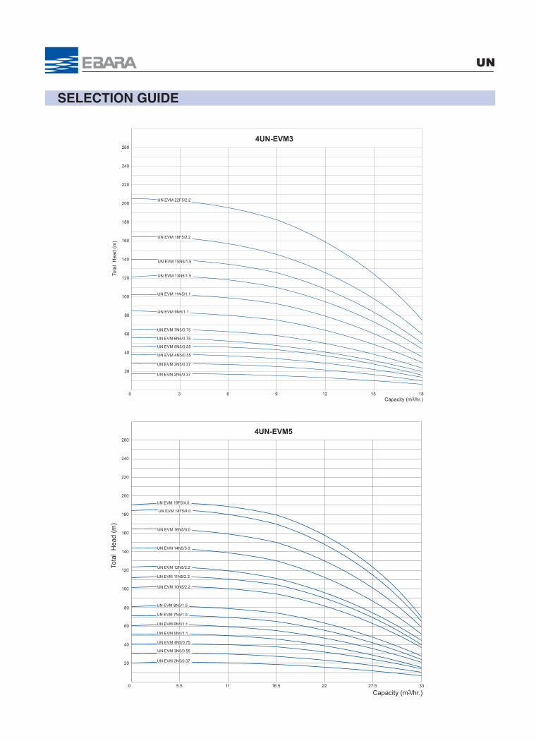
4UN-EVM3
0 18963 12 15Capacity (m3/hr.)
UN EVM 18F5/2.2
UN EVM 13N5/1.5
UN EVM 22F5/2.2
UN EVM 15N5/1.5
UN EVM 9N5/1.1
UN EVM 11N5/1.1
UN EVM 6N5/0.75
UN EVM 7N5/0.75
UN EVM 3N5/0.37
UN EVM 4N5/0.55
UN EVM 5N5/0.55
UN EVM 2N5/0.37
80
0
200
Tota
l H
ead
(m)
120
100
140
160
180
220
240
260
20
40
60
4UN-EVM5
3316.5
UN EVM 5N5/1.1
22 27.5115.5
Capacity (m3/hr.)
UN EVM 11N5/2.2
UN EVM 2N5/0.37
UN EVM 4N5/0.75
UN EVM 3N5/0.55
UN EVM 8N5/1.5
UN EVM 7N5/1.5
UN EVM 6N5/1.1
UN EVM 10N5/2.2
UN EVM 14N5/3.0
UN EVM 12N5/2.2
UN EVM 16N5/3.0
UN EVM 19F5/4.0
UN EVM 18F5/4.0

SELECTION GUIDE
UN
0
200
Tota
l H
ead
(m)
120
100
140
160
180
220
240
260
20
40
60
80
4UN-EVM10
60302010 40 50Capacity (m3/hr.)
UN EVM 4N5/1.5
UN EVM 2N5/0.75
UN EVM 6N5/2.2
UN EVM 5N5/2.2
UN EVM 8N5/3.0
UN EVM 12N5/5.5
UN EVM 11N5/4.0
UN EVM 10N5/4.0
UN EVM 14N5/5.5
UN EVM 15F5/5.5
UN EVM 16F5/7.5
UN EVM 3N5/1.1
UN EVM 18F5/7.5
80
60
40
20
260
240
220
180
160
140
100
120
Tota
l H
ead
(m)
200
0
4UN-EVM18
48 9664 803216Capacity (m3/hr.)
UN EVM 4F5/4.0
UN EVM 3F5/3.0
UN EVM 6F5/5.5
UN EVM 5F5/5.5
UN EVM 2F5/2.2
UN EVM 12F5/11
UN EVM 7F5/7.5
UN EVM 10F5/11
UN EVM 8F5/7.5

SELECTION GUIDE
UN
80
60
40
20
84
260
240
220
4UN-EVM32
180
160
140
100
120
168
Tota
l H
ead
(m)
200
0
280
300
112 1405628Capacity (m3/hr.)
UN EVM 9-0F5/18.5
UN EVM 9-3F5/18.5
UN EVM 8-0F5/15
UN EVM 8-3F5/15
UN EVM 7-0F5/15
UN EVM 7-3F5/15
UN EVM 6-0F5/11
UN EVM 6-3F5/11
UN EVM 5-0F5/11
UN EVM 5-3F5/11
UN EVM 4-0F5/7.5
UN EVM 4-3F5/7.5
UN EVM 3-0F5/5.5
UN EVM 3-3F5/5.5
UN EVM 2-0F5/4.0
UN EVM 2-2F5/3.0
UN EVM 1-0F5/2.2
240
260
180
160
220
240
200
80
60
100
120
140
0
20
40
Tota
l Hea
d (m
)
4UN-EVM45
120 160 2008040Capacity (m3/hr.)
UN EVM 2-2F5/5.5
UN EVM 1-0F5/4.0UN EVM 1-1F5/3.0
UN EVM 4-2F5/15
UN EVM 5-2F5/18.5
UN EVM 4-0F5/15
UN EVM 5-0F5/18.5
UN EVM 6-0F5/22
UN EVM 6-2F5/22
UN EVM 7-2F5/30
UN EVM 3-0F5/11
UN EVM 3-2F5/11
UN EVM 2-0F5/7.5
UN EVM 7-0F5/30
UN EVM 8-2F5/30
SELECTION GUIDE
UN
168
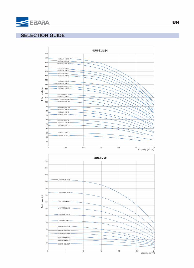
4UN-EVM64
Tota
l Hea
d (m
)
40
20
0
140
120
100
60
80
200
160
180
336
10
30
50
70
90
110
130
150
170
190
210
224 28011256Capacity (m3/hr.)
UN EVM 2-2F5/7.5
UN EVM 1-0F5/5.5
UN EVM 1-1F5/4.0
UN EVM 2-1F5/11
UN EVM 3-3F5/15
UN EVM 2-0F5/11
UN EVM 3-2F5/15
UN EVM 3-0F5/18.5
UN EVM 3-1F5/15
UN EVM 4-1F5/22
UN EVM 4-2F5/18.5
UN EVM 4-3F5/18.5
UN EVM 5-2F5/30UN EVM 5-3F5/30
UN EVM 4-0F5/22
UN EVM 5-1F5/30
UN EVM 6-3F5/30
UN EVM 5-0F5/30
UN EVM 6-0F5/37UN EVM 6-1F5/37
UN EVM 6-2F5/30
UN EVM 7-3F5/37
UN EVM 7-2F5/37
UN EVM 7-1F5/37
0
200
Tota
l H
ead
(m)
24
120
100
140
160
180
5UN-EVM3
220
240
260
12
20
40
60
80
UN EVM 18F5/2.2
84 16 20Capacity (m3/hr.)
UN EVM 13N5/1.5
UN EVM 22F5/2.2
UN EVM 15N5/1.5
UN EVM 9N5/1.1
UN EVM 11N5/1.1
UN EVM 6N5/0.75
UN EVM 7N5/0.75
UN EVM 3N5/0.37
UN EVM 4N5/0.55
UN EVM 5N5/0.55
UN EVM 2N5/0.37

SELECTION GUIDE
UN
60
40
20
19.5
260
240
220
5UN-EVM5
180
160
140
100
120
39
Tota
l H
ead
(m)
200
0
UN EVM 5N5/1.1
80
136.5 26 32.5Capacity (m3/hr.)
UN EVM 19F5/4.0
UN EVM 16N5/3.0
UN EVM 12N5/2.2
UN EVM 14N5/3.0
UN EVM 10N5/2.2
UN EVM 6N5/1.1
UN EVM 7N5/1.5
UN EVM 8N5/1.5
UN EVM 3N5/0.55
UN EVM 4N5/0.75
UN EVM 2N5/0.37
UN EVM 11N5/2.2
UN EVM 18F5/4.0
80
60
40
20
37.5
260
240
220
5UN-EVM10
180
160
140
100
120
75
Tota
l H
ead
(m)
200
0 2512.5 50 62.5Capacity (m3/hr.)
UN EVM 16F5/7.5
UN EVM 15F5/5.5
UN EVM 14N5/5.5
UN EVM 10N5/4.0
UN EVM 11N5/4.0
UN EVM 12N5/5.5
UN EVM 8N5/3.0
UN EVM 5N5/2.2
UN EVM 6N5/2.2
UN EVM 3N5/1.1
UN EVM 2N5/0.75
UN EVM 4N5/1.5
UN EVM 18F5/7.5
SELECTION GUIDE
UN
0
200
Tota
l H
ead
(m)
120
120
100
140
160
180
5UN-EVM18
220
240
260
60
20
40
60
80
4020 80 100
Capacity (m3/hr.)
UN EVM 8F5/7.5
UN EVM 10F5/11
UN EVM 7F5/7.5
UN EVM 12F5/11
UN EVM 2F5/2.2
UN EVM 5F5/5.5
UN EVM 6F5/5.5
UN EVM 3F5/3.0
UN EVM 4F5/4.0
80
60
40
20
105
260
240
220
5UN-EVM32
180
160
140
100
120
210
Tota
l H
ead
(m)
200
0
280
300
7035 140 175Capacity (m3/hr.)
UN EVM 1-0F5/2.2
UN EVM 2-2F5/3.0
UN EVM 2-0F5/4.0
UN EVM 3-3F5/5.5
UN EVM 3-0F5/5.5
UN EVM 4-3F5/7.5
UN EVM 4-0F5/7.5
UN EVM 5-3F5/11
UN EVM 5-0F5/11
UN EVM 6-3F5/11
UN EVM 6-0F5/11
UN EVM 7-3F5/15
UN EVM 7-0F5/15
UN EVM 8-3F5/15
UN EVM 8-0F5/15
UN EVM 9-3F5/18.5
UN EVM 9-0F5/18.5

SELECTION GUIDE
UN
300
260
180
160
220
240
200
80
60
100
120
140
0
20
40
Tota
l Hea
d (m
)
5UN-EVM45
150 200 25010050Capacity (m3/hr.)
UN EVM 2-0F5/7.5
UN EVM 3-2F5/11
UN EVM 3-0F5/11
UN EVM 7-2F5/30
UN EVM 6-2F5/22
UN EVM 6-0F5/22
UN EVM 5-0F5/18.5
UN EVM 4-0F5/15
UN EVM 5-2F5/18.5
UN EVM 4-2F5/15
UN EVM 1-1F5/3.0UN EVM 1-0F5/4.0
UN EVM 2-2F5/5.5
UN EVM 8-2F5/30
UN EVM 7-0F5/30
210
5UN-EVM64
Tota
l Hea
d (m
)
40
20
0
140
120
100
60
80
200
160
180
420
10
30
50
70
90
110
130
150
170
190
70 140 280 350Capacity (m3/hr.)
UN EVM 6-2F5/30
UN EVM 6-1F5/37
UN EVM 6-0F5/37
UN EVM 5-0F5/30
UN EVM 6-3F5/30
UN EVM 5-1F5/30
UN EVM 4-0F5/22
UN EVM 5-3F5/30UN EVM 5-2F5/30
UN EVM 4-3F5/18.5
UN EVM 4-2F5/18.5
UN EVM 4-1F5/22
UN EVM 3-1F5/15
UN EVM 3-0F5/18.5
UN EVM 3-2F5/15
UN EVM 2-0F5/11
UN EVM 3-3F5/15
UN EVM 2-1F5/11
UN EVM 1-1F5/4.0
UN EVM 1-0F5/5.5
UN EVM 2-2F5/7.5
UN EVM 7-1F5/37
UN EVM 7-2F5/37UN EVM 7-3F5/37
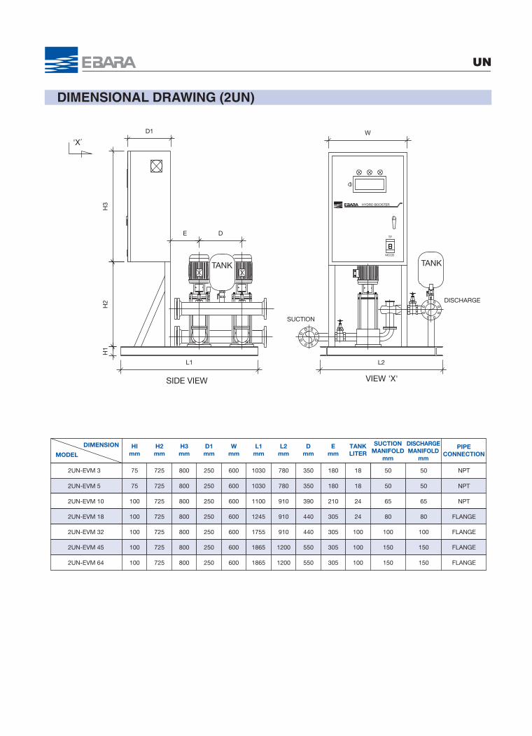
DIMENSIONAL DRAWING (2UN)
UN
HImm
H2mm
H3mm
D1mm
Wmm
L1mm
L2mm
Dmm
Emm
TANKLITER
SUCTIONMANIFOLD
mm
PIPECONNECTION
DISCHARGEMANIFOLD
mm
DIMENSION
MODEL
2UN-EVM 3 75 725 800 250 600 1030 780 350 180 18 50 50 NPT
2UN-EVM 5 75 725 800 250 600 1030 780 350 180 18 50 50 NPT
2UN-EVM 10 100 725 800 250 600 1100 910 390 210 24 65 65 NPT
2UN-EVM 18 100 725 800 250 600 1245 910 440 305 24 80 80 FLANGE
2UN-EVM 32 100 725 800 250 600 1755 910 440 305 100 100 100 FLANGE
2UN-EVM 45 100 725 800 250 600 1865 1200 550 305 100 150 150 FLANGE
2UN-EVM 64 100 725 800 250 600 1865 1200 550 305 100 150 150 FLANGE
W
VIEW 'X'
L2
SUCTION
TANK MCCB
DISCHARGE
TP
HYDRO BOOSTER
H3
E D
TANK
H2
H1
L1
SIDE VIEW
D1
X̀'
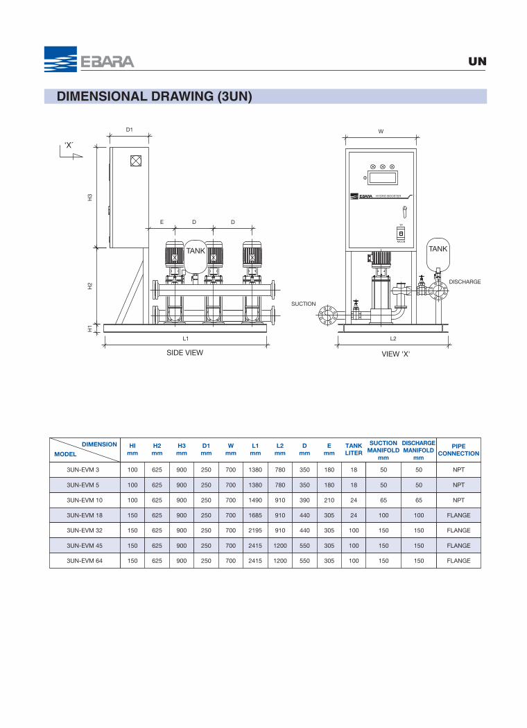
DIMENSIONAL DRAWING (3UN)
UN
HImm
H2mm
H3mm
D1mm
Wmm
L1mm
L2mm
Dmm
Emm
TANKLITER
SUCTIONMANIFOLD
mm
PIPECONNECTION
DISCHARGEMANIFOLD
mm
DIMENSION
MODEL
3UN-EVM 3 100 625 900 250 700 1380 780 350 180 18 50 50 NPT
3UN-EVM 5 100 625 900 250 700 1380 780 350 180 18 50 50 NPT
3UN-EVM 10 100 625 900 250 700 1490 910 390 210 24 65 65 NPT
3UN-EVM 18 150 625 900 250 700 1685 910 440 305 24 100 100 FLANGE
3UN-EVM 32 150 625 900 250 700 2195 910 440 305 100 150 150 FLANGE
3UN-EVM 45 150 625 900 250 700 2415 1200 550 305 100 150 150 FLANGE
3UN-EVM 64 150 625 900 250 700 2415 1200 550 305 100 150 150 FLANGE
TANK
D
H3
E
D1
D
L1
H1
H2
SIDE VIEW
L2
SUCTION
VIEW 'X'
MCCB
TP
HYDRO BOOSTER
DISCHARGE
TANK
W
X̀'

DIMENSIONAL DRAWING (4UN)
UN
HImm
H2mm
H3mm
D1mm
Wmm
L1mm
L2mm
Dmm
Emm
TANKLITER
SUCTIONMANIFOLD
mm
PIPECONNECTION
DISCHARGEMANIFOLD
mm
DIMENSION
MODEL
4UN-EVM 3 100 625 900 250 700 1730 780 350 180 18 65 65 NPT
4UN-EVM 5 100 625 900 250 700 1730 780 350 180 18 65 65 NPT
4UN-EVM 10 150 625 900 250 700 1880 910 390 210 24 80 80 FLANGE
4UN-EVM 18 150 625 900 250 700 2125 910 440 305 24 100 100 FLANGE
4UN-EVM 32 150 625 900 250 700 2635 910 440 305 100 150 150 FLANGE
4UN-EVM 45 150 625 900 250 700 2965 1200 550 305 100 200 200 FLANGE
4UN-EVM 64 150 625 900 250 700 2965 1200 550 305 100 200 200 FLANGE
SUCTION
VIEW 'X'
L2
HYDRO BOOSTER
TANK MCCB
DISCHARGE
TP
W
H3
E D
TANK
D1
SIDE VIEW
H2
H1
L1
D D
X̀'

DIMENSIONAL DRAWING (5UN)
UN
HImm
H2mm
H3mm
D1mm
Wmm
L1mm
L2mm
Dmm
Emm
TANKLITER
SUCTIONMANIFOLD
mm
PIPECONNECTION
DISCHARGEMANIFOLD
mm
DIMENSION
MODEL
5UN-EVM 3 150 500 1100 250 800 2080 780 350 180 18 80 80 FLANGE
5UN-EVM 5 150 500 1100 250 800 2080 780 350 180 18 80 80 FLANGE
5UN-EVM 10 150 500 1100 250 800 2270 910 390 210 24 100 100 FLANGE
5UN-EVM 18 150 500 1100 250 800 2565 910 440 305 24 150 150 FLANGE
5UN-EVM 32 150 500 1100 250 800 3075 910 440 305 100 200 200 FLANGE
5UN-EVM 45 150 500 1100 250 800 3515 1200 550 305 100 200 200 FLANGE
5UN-EVM 64 150 500 1100 250 800 3515 1200 550 305 100 200 200 FLANGE
SUCTION
L2
VIEW 'X'
MCCB
TP
HYDRO BOOSTER
DISCHARGE
TANK
W
H3
E D
TANK
D1
SIDE VIEW
D D D
H2
H1
L1
X̀'