Embed Size (px)
Citation preview
7/27/2019 Earthing IEEE80 Final(1)
http://slidepdf.com/reader/full/earthing-ieee80-final1 1/16
DESIGN PROCEDURE BLOCK DIAGRAM
FIELD DATA
A,r
CONDUCTOR SIZEts,d,Io
TOUCH & STEPCRITERIA
Etouch70, Estep70
INITIAL DESIGND,n,LT,h
GRID RESISTANCERg,LT
GRID CURRENTIG
GPR < Etouch
MESH & STEPVOLTAGES
Em,Es,Km,Ks,Ki,Kii
Es<Estep
Em<Etouch
DETAILDESIGN
MODIFY DESIGND,n,LT,LR
YES
YES
YES
NO
NO
NO
7/27/2019 Earthing IEEE80 Final(1)
http://slidepdf.com/reader/full/earthing-ieee80-final1 2/16
EARTHING CALCULATION
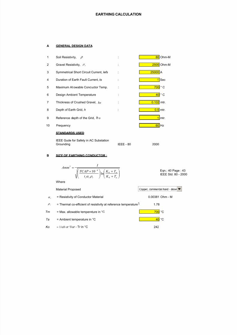
A GENERAL DESIGN DATA
1 Soil Resistivity, : 80 Ohm-M
2 Gravel Resistivity, : 2500 Ohm-M
3 Symmetrical Short Circuit Current, Iefs : 25000 A
4 Duration of Earth Fault Current, ts : 1 Sec
5 Maximum Allowable Conductor Temp. : 700 ° C
6 Design Ambient Temperature : 40 ° C
7 Thickness of Crushed Gravel, : 0.102 mtr.
8 Depth of Earth Grid, h : 0.5 mtr.
9 Reference depth of the Grid, h o 1 mtr.
10 Frequency 60 Hz
STANDARDS USED
IEEE Gude for Safety in AC Substation
Grounding IEEE - 80 2000
B SIZE OF EARTHING CONDUCTOR :
Eqn.: 40 Page : 43
IEEE Std. 80 - 2000
Where
Material Proposed
= Resistivity of Conductor Material 0.00381 Ohm - M
= Thermal co-efficient of resistivity at reference temperature 1.78
Tm = Max. allowable temperature in °C 700 °C
Ta = Ambient temperature in °C 40 °C
Ko = 1/a0 or 1/ar - Tr in °C 242
=
a
m
r r c T K
T K
t
TCAP
I Amm
0
0
4
2
ln10
r a
r r
r a
s r
r
hs
7/27/2019 Earthing IEEE80 Final(1)
http://slidepdf.com/reader/full/earthing-ieee80-final1 3/16
EARTHING CALCULATION
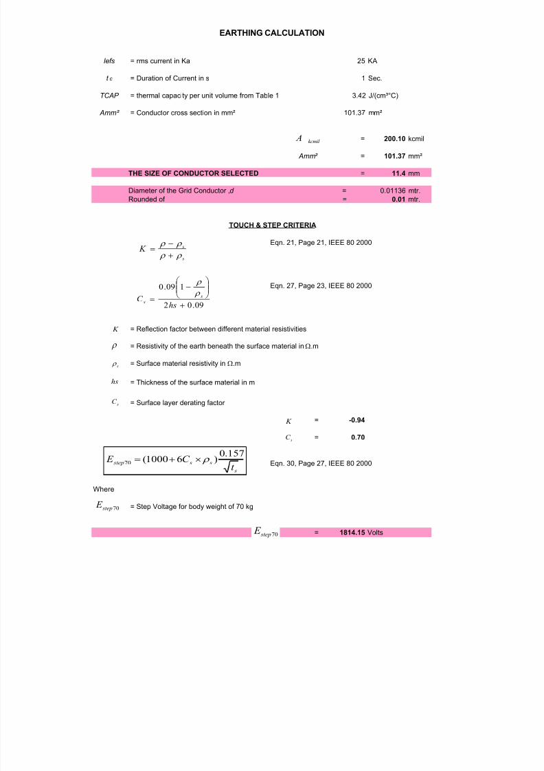
Iefs = rms current in Ka 25 KA
t c = Duration of Current in s 1 Sec.
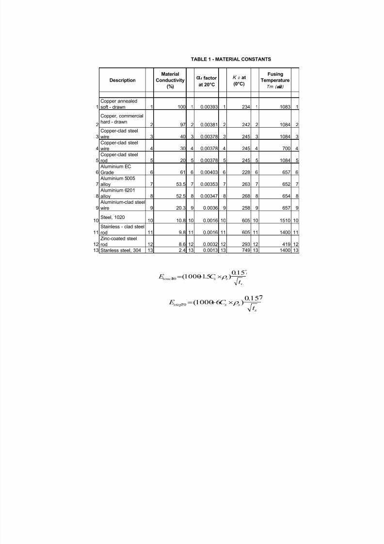
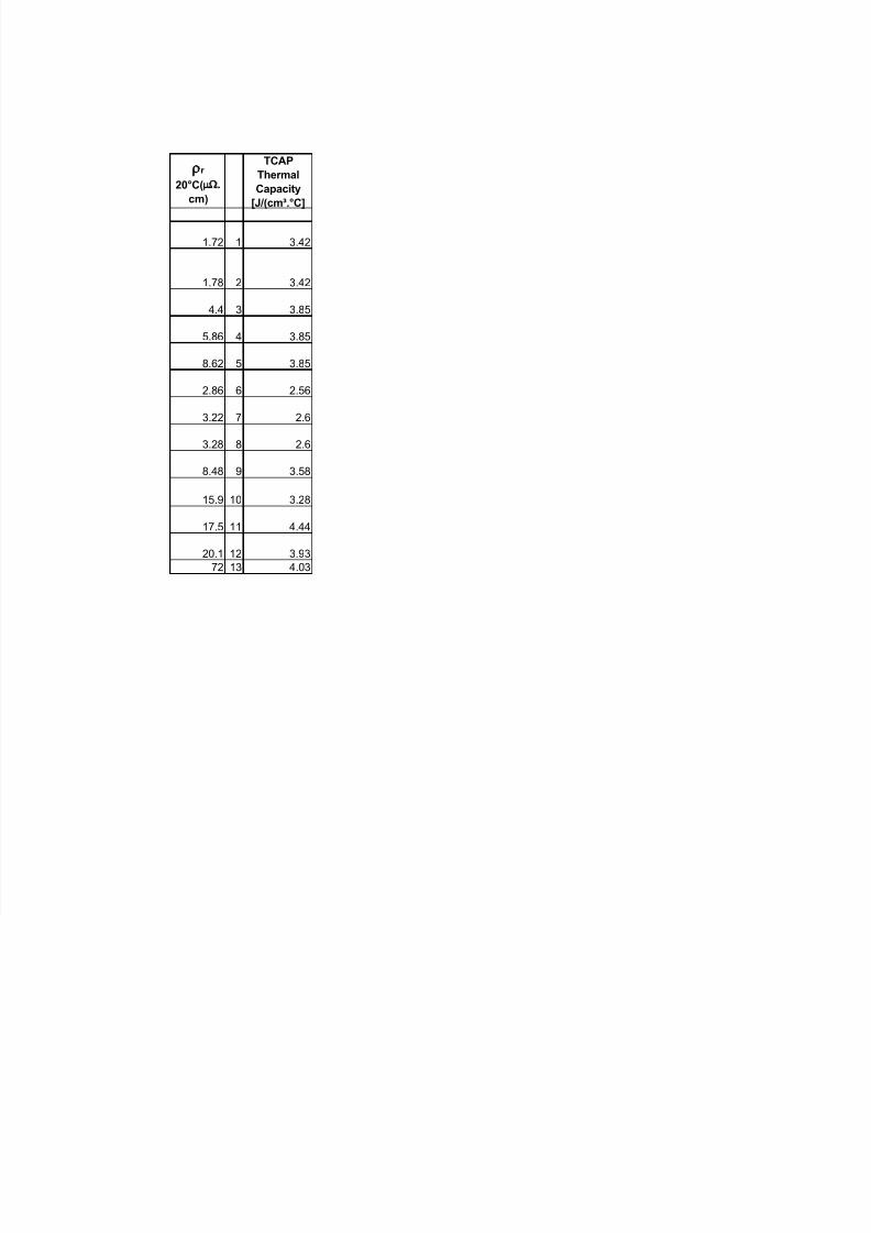
TCAP = thermal capacity per unit volume from Table 1 3.42 J/(cm³°C)
Amm² = Conductor cross section in mm² 101.37 mm²
= 200.10 kcmil
Amm² = 101.37 mm²
THE SIZE OF CONDUCTOR SELECTED = 11.4 mm
Diameter of the Grid Conductor ,d = 0.01136 mtr.
Rounded of = 0.01 mtr.
Eqn. 21, Page 21, IEEE 80 2000
Eqn. 27, Page 23, IEEE 80 2000
= Reflection factor between different material resistivities
= Resistivity of the earth beneath the surface material in W.m
= Surface material resistivity in W.m
= Thickness of the surface material in m
= Surface layer derating factor
= -0.94
= 0.70
Eqn. 30, Page 27, IEEE 80 2000
Where
= Step Voltage for body weight of 70 kg
= 1814.15 Volts
TOUCH & STEP CRITERIA
kcmil A
s
s K r r
r r
=
K
r
s r
K
09.02
109.0
=hs
C s
s
r
r
sC
hs
sC
70 step E
70 step E
s
s s stept
C E 157.0
)61000(70 r =
7/27/2019 Earthing IEEE80 Final(1)
http://slidepdf.com/reader/full/earthing-ieee80-final1 4/16
7/27/2019 Earthing IEEE80 Final(1)
http://slidepdf.com/reader/full/earthing-ieee80-final1 5/16
EARTHING CALCULATION
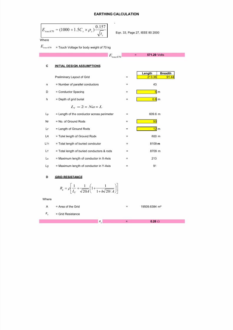
E MAXIMUM GRID CURRENT
Where
= Maximum grid current in A 25000 A
X/R= 10
Ta= 0.0265258
= Decrement factor for the entire duration of fault, given in s 1.0131761
= 25329.40268 A
F GROUND POTENTIAL RISE
= 6639.6 V
The safety to personnel is specified by IEEE 80, which requires to limit the development of
electrical potential to dangerous value during earth fault current.
The regulation stipulates the following parameters to be within the permissible limit
a) Step Voltage (Foot to Foot Contact)
b) Touch Voltage(Hand to Foot Contact)
A Mesh Voltage
Eqn. 80, Page 91,
IEEE 80, 2000
= Corrective factor for current irregu-larity
Where
CALCULATION FOR ACTUAL DERIVED STEP & MESH VOLTAGE
VERIFICATION FOR HUMAN SAFETY
R
Ly x
r C
imG
Ll L
L L
K K I Design Emesh
=
2222.155.1
)(r
Ki
g I
g f G I D I =
f D
G I
g G R I GPR =
GPR
n K i 148.0644.0 =
d cba nnnnn =

7/27/2019 Earthing IEEE80 Final(1)
http://slidepdf.com/reader/full/earthing-ieee80-final1 6/16
EARTHING CALCULATION
= 26.6
= 1 for square grids = 1
= 1 for square and rectangular grids = 1
= 1 for square, rectangular and L-shaped gri = 1
= 26.60
= 4.58
= Spacing factor for Mesh Voltage Eqn. 68 Page 113 IEEE 80
Eqn. 81, Page 93
IEEE 80, 2000
Where
= Corrective wieghting factor that adjusts the effect of inner conductors on the corner mesh
= 0.81
= 1.00 With Rods
= Corrective weighting factor that empasising the grid depth
=
Where
= Reference depth of grid = 1
= Depth of the ground grid conductor = 0.5
= 1.22
= 0.50
= 511.43 Volts
Km
=
12
8ln
48
2
16
ln
2
122
n Kh
Kii
d
h
Dd
h D
hd
D Km
Kii
Kh
ho
h1
ho
h
Kh
Km
)( Design Emesh
n
ii
n
K 2
)2(
1
=
Kii
P
T a
Ln =
an
bn
c
n
d n
n
Ki
Kii
7/27/2019 Earthing IEEE80 Final(1)
http://slidepdf.com/reader/full/earthing-ieee80-final1 7/16
EARTHING CALCULATION
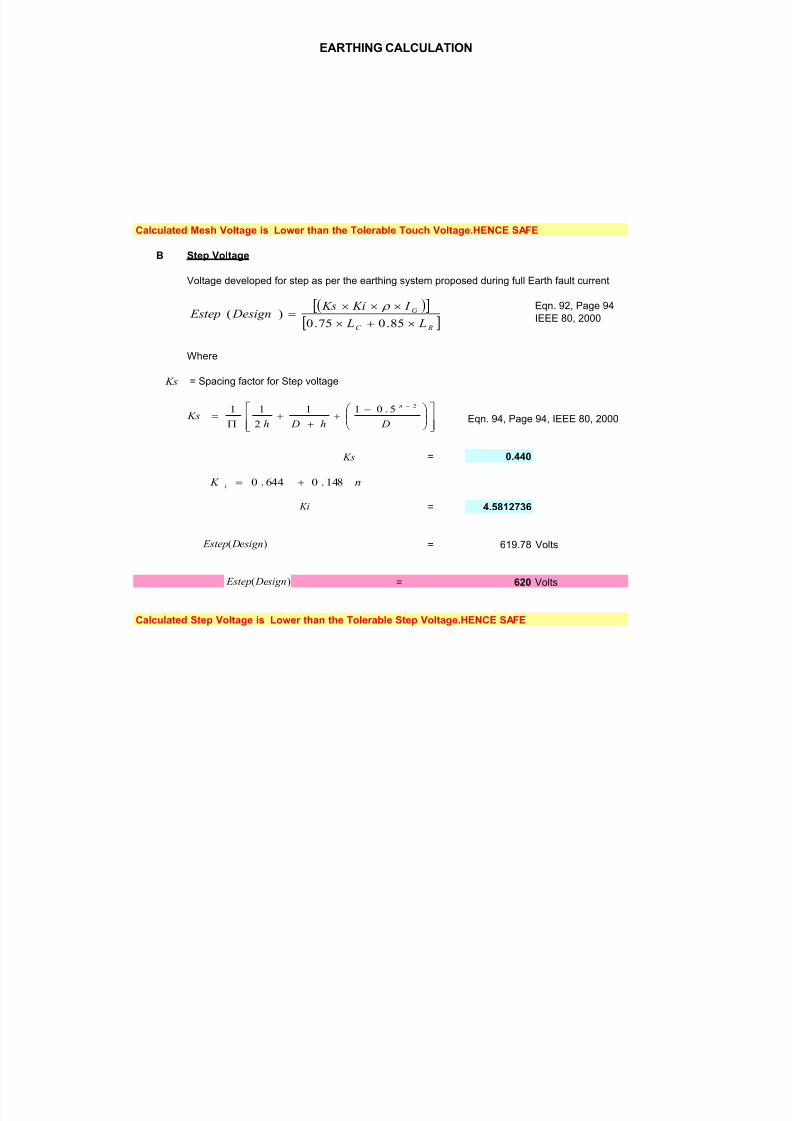
Calculated Mesh Voltage is Lower than the Tolerable Touch Voltage.HENCE SAFE
B Step Voltage
Voltage developed for step as per the earthing system proposed during full Earth fault current
Eqn. 92, Page 94
IEEE 80, 2000
Where
= Spacing factor for Step voltage
Eqn. 94, Page 94, IEEE 80, 2000
= 0.440
= 4.5812736
= 619.78 Volts
= 620 Volts
Calculated Step Voltage is Lower than the Tolerable Step Voltage.HENCE SAFE
RC
G
L L
I Ki Ks Design Estep
=
85.075.0)(
r
Ks
=
Dh Dh Ks
n 25.011
2
11
Ks
Ki
)( Design Estep
)( Design Estep
n K i 148.0644.0 =

7/27/2019 Earthing IEEE80 Final(1)
http://slidepdf.com/reader/full/earthing-ieee80-final1 8/16
EARTHING CALCULATION

7/27/2019 Earthing IEEE80 Final(1)
http://slidepdf.com/reader/full/earthing-ieee80-final1 9/16
EARTHING CALCULATION

7/27/2019 Earthing IEEE80 Final(1)
http://slidepdf.com/reader/full/earthing-ieee80-final1 10/16
EARTHING CALCULATION

7/27/2019 Earthing IEEE80 Final(1)
http://slidepdf.com/reader/full/earthing-ieee80-final1 11/16
EARTHING CALCULATION

7/27/2019 Earthing IEEE80 Final(1)
http://slidepdf.com/reader/full/earthing-ieee80-final1 12/16
EARTHING CALCULATION

7/27/2019 Earthing IEEE80 Final(1)
http://slidepdf.com/reader/full/earthing-ieee80-final1 13/16
EARTHING CALCULATION
7/27/2019 Earthing IEEE80 Final(1)
http://slidepdf.com/reader/full/earthing-ieee80-final1 14/16
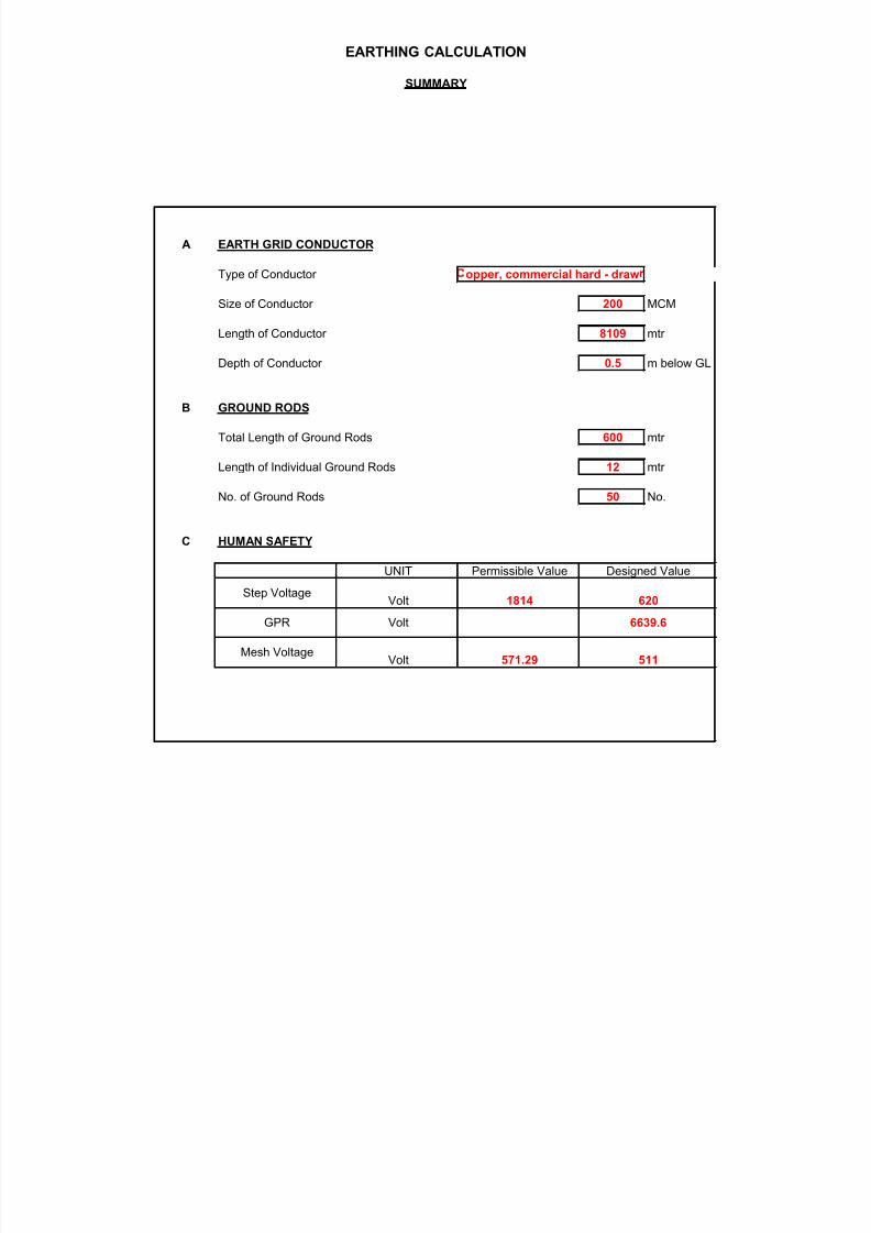
EARTHING CALCULATION
SUMMARY
A EARTH GRID CONDUCTOR
Type of Conductor
Size of Conductor 200 MCM
Length of Conductor 8109 mtr
Depth of Conductor 0.5 m below GL
B GROUND RODS
Total Length of Ground Rods 600 mtr
Length of Individual Ground Rods 12 mtr
No. of Ground Rods 50 No.
C HUMAN SAFETY
Mesh Voltage511
620
Volt
1814
571.29
GPR Volt 6639.6
Permissible Value
Volt
opper, commercial hard - draw
Step Voltage
UNIT Designed Value
7/27/2019 Earthing IEEE80 Final(1)
http://slidepdf.com/reader/full/earthing-ieee80-final1 15/16
7/27/2019 Earthing IEEE80 Final(1)
http://slidepdf.com/reader/full/earthing-ieee80-final1 16/16
rr
20°C(mW.cm)
TCAP
Thermal
Capacity
[J/(cm³.°C]
1.72 1 3.42
1.78 2 3.42
4.4 3 3.85
5.86 4 3.85
8.62 5 3.85
2.86 6 2.56
3.22 7 2.6
3.28 8 2.6
8.48 9 3.58
15.9 10 3.28
17.5 11 4.44
20.1 12 3.9372 13 4.03