Embed Size (px)
Citation preview
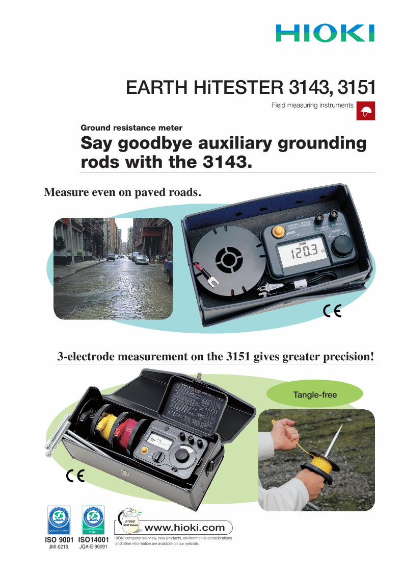
EARTH HiTESTER 3143, 3151Field measuring instruments
Ground resistance meter
Say goodbye auxiliary grounding rods with the 3143.
Measure even on paved roads.
3-electrode measurement on the 3151 gives greater precision!
Tangle-free

1
The 3143 requires no auxiliary grounding rods, making measurement easy.
Using the 31431. Wire as shown in the diagram.2. Turn the rotary knob to measure. As the rotary knob is turned, the lowest resistance value that is
displayed is the grounding resistance value.
Presenting a next-generation ground resistance meter
Grounding is increasingly important for the safe operation and maintenance of communications equipment and many other types of facilities. However, in an urban environment where the ground is covered with concrete or asphalt, conventional measurement methods that require inserting auxiliary grounding electrodes are difficult to use. The 3143 uses a new measurement principle that makes auxiliary grounding electrodes unnecessary, so it can be used to measure ground resistance on paved roads.
Easy-grip elastomer knob
Bar graph display makes it easy to find measured resistance.Turn the rotary knob so that the graduations are centered.
Dust-resistant switch
Large, easy to read LCD display
Convenient Features
Rx
String along the ground (20m)
EarthReturn
Common ground resistance meters such as the 3151 measure the resistance using a frequency between 500 Hz and several kHz. The 3143 uses a frequency between 100 kHz and 1.5 MHz, close to that of a lightning surge. Therefore, measurement errors can result if the 3143 is used in situations such as the following. In these instances, we recommend using Model 3151.• Electricalgroundingormeshgrounding.• Electricalpowerequipmentgrounding.• Whenthemeasurementpointislocatedatadistancefromthe
insertion point of the grounding electrode.
Differences from the Previous Instrument (Model 3151)
The 3143 obtains ground resistance Rx by measuring the loop impedance of the closed path that goes from the lead wire to earth, then back to a return line which is strung along the surface of the earth.The drawing below shows an equivalent circuit, where Rx is the ground resistance of the object being measured, C is the capacitance of the return wire relative to ground, and L is the inductance of the measurement cable.By varying the frequency of the measurement signal source so that LCR is serially resonant, the ground resistance Rx can be determined as follows. Rx = Vm / (Vc - Vm) × Ro
Here, Vc is the signal source voltage, Vm is the voltage between the measurement terminals, and Ro is the signal source output resistance.
Withthe3143youturnthemeasurementknobtovarythesignalsource frequency. As the knob is turned, the smallest value that appears (the value at the resonance point) is the ground resistance value Rx.
Measurement Principle of the 3143
FeaturesAuxiliary grounding rods are unnecessary, greatly reducing time and effort. Measurement can be done easily on concrete or asphalt
pavements.Measurements are easy to read. A large digital display shows measured values.Resistant to dirt. Dust resistance of parts such as the power switch and
measurement dial has been increased and durability has been improved.
The 3143 is most appropriate for measuring the ground resistance of an individually grounded rod-shaped electrode.
Lead Wire
Return Wire
GroundGround being measured
Equivalent Circuit Model Equivalent Circuit At Resonance
3143 3143
2
Count on The 3151 for Dependable Measurements
E C
RxRo
5 M minimum
AC 250 V max
Simple Measurement (2 Electrode Method)1. Wire as shown in the diagram. (Example of power
supply grounding line connection)2. Set the 2/3 electrode method switch to 2 electrode
measurement.3. Check for grounding voltage in the grounding voltage
range.4. Take measurements, choosing either ×10 or ×100. While pressing themeasurement button, turn the resistance
dial knob and read the resistance when the galvanometer reaches a balance. (Measured value = Rx + Ro.)
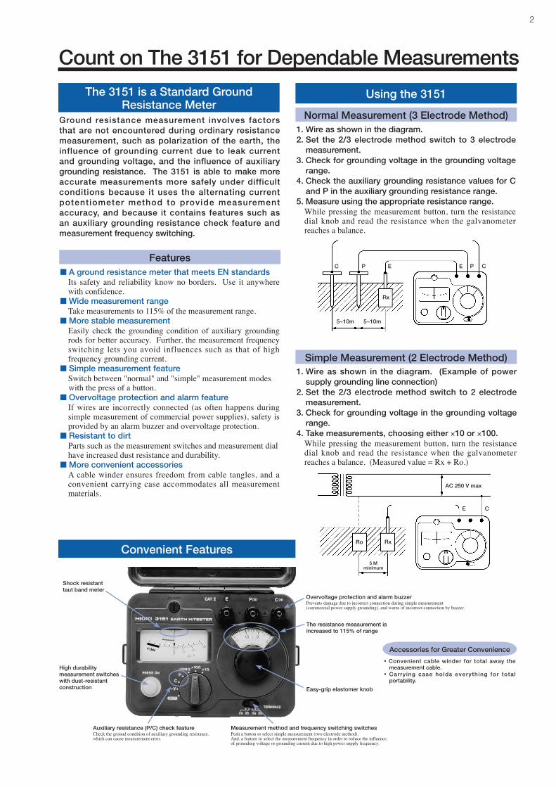
Using the 3151
Normal Measurement (3 Electrode Method)1. Wire as shown in the diagram.2. Set the 2/3 electrode method switch to 3 electrode
measurement.3. Check for grounding voltage in the grounding voltage
range.4. Check the auxiliary grounding resistance values for C
and P in the auxiliary grounding resistance range.5. Measure using the appropriate resistance range. While pressing themeasurementbutton, turn the resistance
dial knob and read the resistance when the galvanometer reaches a balance.
5~10m
Rx
EPC E P C
5~10m
A ground resistance meter that meets EN standards Its safety and reliability know no borders. Use it anywhere
with confidence. Wide measurement range Take measurements to 115% of the measurement range. More stable measurement Easily check the grounding condition of auxiliary grounding
rods for better accuracy. Further, the measurement frequency switching lets you avoid influences such as that of high frequency grounding current.
Simple measurement feature Switch between "normal" and "simple" measurement modes with the press of a button. Overvoltage protection and alarm feature If wires are incorrectly connected (as often happens during
simple measurement of commercial power supplies), safety is provided by an alarm buzzer and overvoltage protection.
Resistant to dirt Parts such as the measurement switches and measurement dial
have increased dust resistance and durability. More convenient accessories A cable winder ensures freedom from cable tangles, and a
convenient carrying case accommodates all measurement materials.
Features
The 3151 is a Standard Ground Resistance Meter
Ground resistance measurement involves factors that are not encountered during ordinary resistance measurement, such as polarization of the earth, the influence of grounding current due to leak current and grounding voltage, and the influence of auxiliary grounding resistance. The 3151 is able to make more accurate measurements more safely under difficult conditions because it uses the alternating current potentiometer method to provide measurement accuracy, and because it contains features such as an auxiliary grounding resistance check feature and measurement frequency switching.
Accessories for Greater Convenience
• Convenient cable winder for total away the measurement cable.
• Carrying case holds everything for total portability.
Auxiliary resistance (P/C) check featureCheck the ground condition of auxiliary grounding resistance, which can cause measurement error.
Measurement method and frequency switching switchesPush a button to select simple measurement (two electrode method).And, a feature to select the measurement frequency in order to reduce the influence of grounding voltage or grounding current due to high power supply frequency.
The resistance measurement is increased to 115% of range
High durability measurement switches with dust-resistant construction
Shock resistant taut band meter
Overvoltage protection and alarm buzzerPrevents damage due to incorrect connection during simple measurement (commercial power supply grounding), and warns of incorrect connection by buzzer.
Easy-grip elastomer knob
Convenient Features

3
3151 Specifications 3143 Specifications
Influence of auxiliary grounding resistance: ± 5% for a fluctuation of 0 to 5 kΩ
Influence of grounding voltage:± 2% for 0 to 5 V± 5% for 0 to 10 V (for 50/60 Hz)± 5% for 0 to 3 V (for DC, 162/3, 400 Hz)
Influence of power supply voltage: within nominal deviation for DC 6 to 10 V Operating method: AC potentiometer method Open circuit voltage: AC 50V max Measurement current:
AC 15 mA max (AC 3 mA max when using the two electrode method) Measurement frequency:
575 Hz (with 3a or 2a selected) or 600 Hz (with 3b or 2b selected) Operating temperature and humidity: 0to40˚C,80%rhmaximum(nocondensation)
Storage temperature and humidity: -10to50˚C,80%rhmaximum(nocondensation)
Applicable standards:•Groundingresistancemeter:EN61557-5•Safety:EN61010-1+A2/EN61010-2-031,overvoltagecategoryII,
pollution level 2•EMC:EN61326-1+A1
Environment protection:IP40(EN60529:1991) Overvoltage protection: AC250V,1minute(betweenE-P(S),E-C(H)terminals)
Power supply: R6P manganese battery × 6, or LR6 alkaline battery × 6 Operating time: Approx 350 operations (using R6P battery) Approx 1100 operations (using LR6 battery)
(30 seconds measurement / 30 seconds off condition) Approximate dimensions and weight: 164(W)×119(H)×88(D)mm(notincludingprotrusions), 800g(mainunitonly)
Accessories:AUXILIARY GROUNDING RODS 9214 × 2MEASURING CABLE 9215 (black 5 m, yellow 10 m, red 20 m, one each; CABLE WINDER 9216 × 3)PORTABLE CASE 9393
Optional accessoryEARTH NETS 9050 (set of two)Use in places where auxiliary grounding rods cannot be inserted (but where water can penetrate)
Display: 4-digitLCD,valuesabove999.9Ω displayed as "OF" Influence of grounding voltage: ± 5% rdg. for 0 to 10 V Principle of operation: voltage comparison method
(Measurement of voltage at loop impedance serial resonance) Open circuit voltage: AC 1 Vp typ Measurement current:AC3.6mAmax(Withterminalsshorted) Measurement frequency: 100 kHz to 1.5 MHz Features:•Energysavingmode:after3minuteswithnooperation,displays
"HOLD" and enters the standby state•Resonanceindicator:bargraphindicatorshowsapproximate
location of resonance point•Batterycheck:batterylightflasheswhenthepowersupplyvoltage
drops Operating temperature and humidity: 0to40˚C,80%rhmaximum(nocondensation)
Storage temperature and humidity: -10to50˚C,80%rhmaximum(nocondensation)
Applicable standards:•Safety:EN61010-1+A2,overvoltagecategoryI,pollutionlevel2•EMC:EN61326-1+A1classB
Power supply: LR6 alkaline battery × 4 Operating time:8hourscontinuous(23˚Creferencevalue) Approximate dimensions and weight: 155(W)×98(H)×49(D)mm(notincludingprojections), 380g(mainunitonly)
Accessories:MEASURING CABLE 9265 (black 1 m, red 20 m, one each; CABLE WINDER 9216 × 1)PORTABLE CASE 9338
(Temperatureandhumidity:23˚C±5˚C,80%rhmaximum)(100Ω/1000Ω ranges only with 2 electrode measurement)
(Temperatureandhumidity:Withinratedoperatingtemperatureandhumidityrange.)
MeasurementItem Measurement Range Accuracy
GroundingResistance
20.0 to 49.9 Ω ± 10% rdg.
50.0 to 500.0 Ω ± 5% rdg.
MeasurementItem Measurement Range Nominal
Deviation
Grounding Resistance
10 Ω (0 to 11.5 Ω) ± 2.5 % f.s.
100 Ω (0 to 115 Ω) ± 2.5 % f.s.
1000 Ω (0 to 1150 Ω) ± 2.5 % f.s.
GroundingVoltage 30 V (0 to 30 V) ± 3.0 % f.s.
HEAD OFFICE :81 Koizumi, Ueda, Nagano, 386-1192, JapanTEL +81-268-28-0562 / FAX +81-268-28-0568 E-mail: [email protected]
HIOKI USA CORPORATION :6 Corporate Drive, Cranbury, NJ 08512 USATEL +1-609-409-9109 / FAX +1-609-409-9108E-mail: [email protected]
DISTRIBUTED BY
All information correct as of Sep. 30, 2009. All specifications are subject to change without notice. 3143E5-99E Printed in Japan
HIOKI (Shanghai) Sales & Trading Co., Ltd. :1608-1610 Shanghai Times Square Office, 93 Huai Hai Zhong Road, Shanghai, P.R.China POSTCODE: 200021TEL +86-21-6391-0090/0092 FAX +86-21-6391-0360E-mail: [email protected] Office :A-2602 Freetown, 58 Dong San Huan Nan RoadBeijing, P.R.China POSTCODE: 100022TEL +86-10-5867-4080/4081 FAX +86-10-5867-4090E-mail: [email protected] Office :Room A-3206, Victory PlazaServices Center, No.103, Tiyuxi Road, Guangzhou, P.R.China POSTCODE:510620TEL +86-20-38392673/2676 FAX +86-20-38392679E-mail: [email protected]


![[Ex 3151] Wiring Book](https://img.dokumen.tips/doc/110x75/56d6bf811a28ab30169680fc/ex-3151-wiring-book.jpg)